

Page 1
GV-IP LPR Camera 5R /
GV-Hybrid LPR Camera 10R
User's Manual
Before attempting to connect or operate this product,
please read these instructions carefully and save this manual for future use.
LPRCAM5RV10-10RV102-A
Page 2

© 2013 GeoVision, Inc. All rights reserved.
Under the copyright laws, this manual may not be copied, in whole or in part, without the
written consent of GeoVision.
Every effort has been made to ensure that the information in this manual is accurate.
GeoVision, Inc. makes no expressed or implied warranty of any kind and assumes no
responsibility for errors or omissions. No liability is assumed for incidental or consequential
damages arising from the use of the information or products contained herein. Features and
specifications are subject to change without notice.
GeoVision, Inc.
9F, No. 246, Sec. 1, Neihu Rd.,
Neihu District, Taipei, Taiwan
Tel: +886-2-8797-8377
Fax: +886-2-8797-8335
http://www.geovision.com.tw
Trademarks used in this manual: GeoVision, the GeoVision logo and GV series products are
trademarks of GeoVision, Inc. Windows and Windows XP are registered trademarks of
Microsoft Corporation.
September 2013
Page 3

Preface
Welcome to the GV-Hybrid LPR Camera 10R / GV-IP LPR Camera 5R User’s Manual.
The GV-IP LPR Camera has a series of models designed to meet different needs. This
manual is designed for the following models and firmware versions:
Models Firmware Version
GV-Hybrid LPR Camera 10R 1.02
GV-IP LPR Camera 5R 1.0
i
Page 4

Contents
Naming Definition..................................................................................................... v
Options .................................................................................................................... v
Note for Connecting to GV-System......................................................................... v
Note for Installing Camera Outdoor....................................................................... vi
Chapter 1 Introduction........................................................................................... 1
1.1 GV-Hybrid LPR Camera 10R....................................................................................1
1.1.1 Features........................................................................................................2
1.1.2 System Requirements ..................................................................................3
1.1.3 Packing List ..................................................................................................4
1.1.4 Overview.......................................................................................................5
1.1.5 Device Installation.........................................................................................6
1.1.6 Connecting the Camera..............................................................................10
1.2 GV-IP LPR Camera 5R...........................................................................................12
1.2.1 Features......................................................................................................13
1.2.2 System Requirements ................................................................................14
1.2.3 Packing List ................................................................................................15
1.2.4 Overview.....................................................................................................16
1.2.5 Device Installation.......................................................................................17
1.2.6 Connecting the Camera..............................................................................18
1.2.7 Adjusting the Angles ...................................................................................19
1.2.8 Replacing the Silica Gel Bag ......................................................................22
1.2.9 Installing the Sun-Shield Cover ..................................................................23
Chapter 2 Getting Started.................................................................................... 24
2.1 Looking Up the IP Address.....................................................................................24
2.2 Accessing Your Surveillance Images...................................................................... 27
2.3 Configuring the Basics............................................................................................ 28
Chapter 3 Guest Mode and Live View Panel...................................................... 29
3.1 The Live View Window ...........................................................................................30
3.2 The Control Panel of the Live View Window ..........................................................32
3.3 Snapshot of a Live Video........................................................................................35
3.4 Video Recording..................................................................................................... 35
3.5 Picture-in-Picture and Picture-and-Picture View.....................................................36
3.6 Alarm Notification ................................................................................................... 38
3.7 Video and Audio Configuration............................................................................... 39
3.8 Remote Configuration............................................................................................. 40
3.9 Camera Name Display ...........................................................................................40
ii
Page 5

3.10 Image Enhancement ............................................................................................ 40
Chapter 4 Administrator Mode............................................................................ 41
4.1 Video & Motion .......................................................................................................43
4.1.1 Video Settings.............................................................................................44
4.1.2 Motion Detection.........................................................................................49
4.1.3 Privacy Mask ..............................................................................................50
4.1.4 Text Overlay................................................................................................51
4.1.5 Tampering Alarm.........................................................................................52
4.2 Events & Alerts ....................................................................................................... 54
4.2.1 E-mail..........................................................................................................55
4.2.2 FTP.............................................................................................................57
4.2.3 Center V2....................................................................................................59
4.2.4 VSM............................................................................................................61
4.2.5 Backup Center............................................................................................63
4.2.6 GV-Video Gateway / GV-Recording Server................................................65
4.2.7 ViewLog......................................................................................................67
4.2.8 RTSP..........................................................................................................68
4.3 Monitoring...............................................................................................................69
4.3.1 GV-Hybrid LPR Camera 10R......................................................................69
4.3.2 GV-IP LPR Camera 5R...............................................................................70
4.4 Recording Schedule ...............................................................................................71
4.4.1 Recording Schedule Settings .....................................................................71
4.5 Network .................................................................................................................. 72
4.5.1 LAN Configuration ......................................................................................72
4.5.2 Advanced TCP/IP .......................................................................................74
4.5.3 IP Filtering...................................................................................................78
4.5.4 SNMP Settings ...........................................................................................79
4.6 Management...........................................................................................................81
4.6.1 Date and Time Settings..............................................................................81
4.6.2 GPS Maps Settings ....................................................................................83
4.6.3 Storage Settings .........................................................................................85
4.6.4 User Account ..............................................................................................88
4.6.5 Log Information...........................................................................................89
4.6.6 System Log.................................................................................................90
4.6.7 Tools ...........................................................................................................92
4.6.8 Language....................................................................................................94
Chapter 5 Advanced Applications...................................................................... 95
5.1 Upgrading System Firmware ..................................................................................95
iii
Page 6

5.1.1 Using the Web Interface .............................................................................96
5.1.2 Using the GV-IP Device Utility....................................................................97
5.2 Backing Up and Restoring Settings......................................................................100
5.3 Restoring to Factory Default Settings...................................................................102
5.3.1 Using the Web Interface ...........................................................................102
5.3.2 Directly on the Camera.............................................................................102
5.4 Verifying Watermark ............................................................................................. 103
5.4.1 Accessing AVI Files ..................................................................................103
5.4.2 Running Watermark Proof ........................................................................103
5.4.3 The Watermark Proof Window..................................................................104
Chapter 6 DVR Configurations ......................................................................... 105
6.1 Setting Up IP Cameras.........................................................................................107
6.1.1 Customizing Camera Settings ..................................................................110
6.2 Remote Monitoring with Multi View ...................................................................... 112
6.3 Remote Monitoring with E-Map ............................................................................ 114
Chapter 7 CMS Configurations..........................................................................116
7.1 Center V2 ............................................................................................................. 116
7.2 VSM...................................................................................................................... 118
7.3 Dispatch Server.................................................................................................... 119
Chapter 8 Smart Device Connection ..................................................................... 120
8.1 Android .................................................................................................................121
8.1.1 Connecting to the Camera........................................................................121
8.1.2 Accessing Live View .................................................................................123
8.2 Apple ....................................................................................................................125
8.2.1 Connecting to the Camera........................................................................126
8.2.2 Accessing Live View .................................................................................127
Specifications....................................................................................................... 129
GV-Hybrid LPR Camera 10R........................................................................................129
GV-IP LPR Camera 5R .................................................................................................133
Appendix............................................................................................................... 136
A. The CGI Command...................................................................................................136
B. RTSP Protocol Support.............................................................................................137
C. Settings for Internet Explorer 8 or later.....................................................................138
iv
Page 7

Naming Definition
GeoVision Analog and Digital Video Recording Software. The
GV-System
GV-System also refers to Multicam System, GV-NVR System,
GV-DVR System and GV-Hybrid DVR System at the same time.
Options
Optional devices can expand your camera’s capabilities and versatility. Contact your dealer
for more information.
Device Description
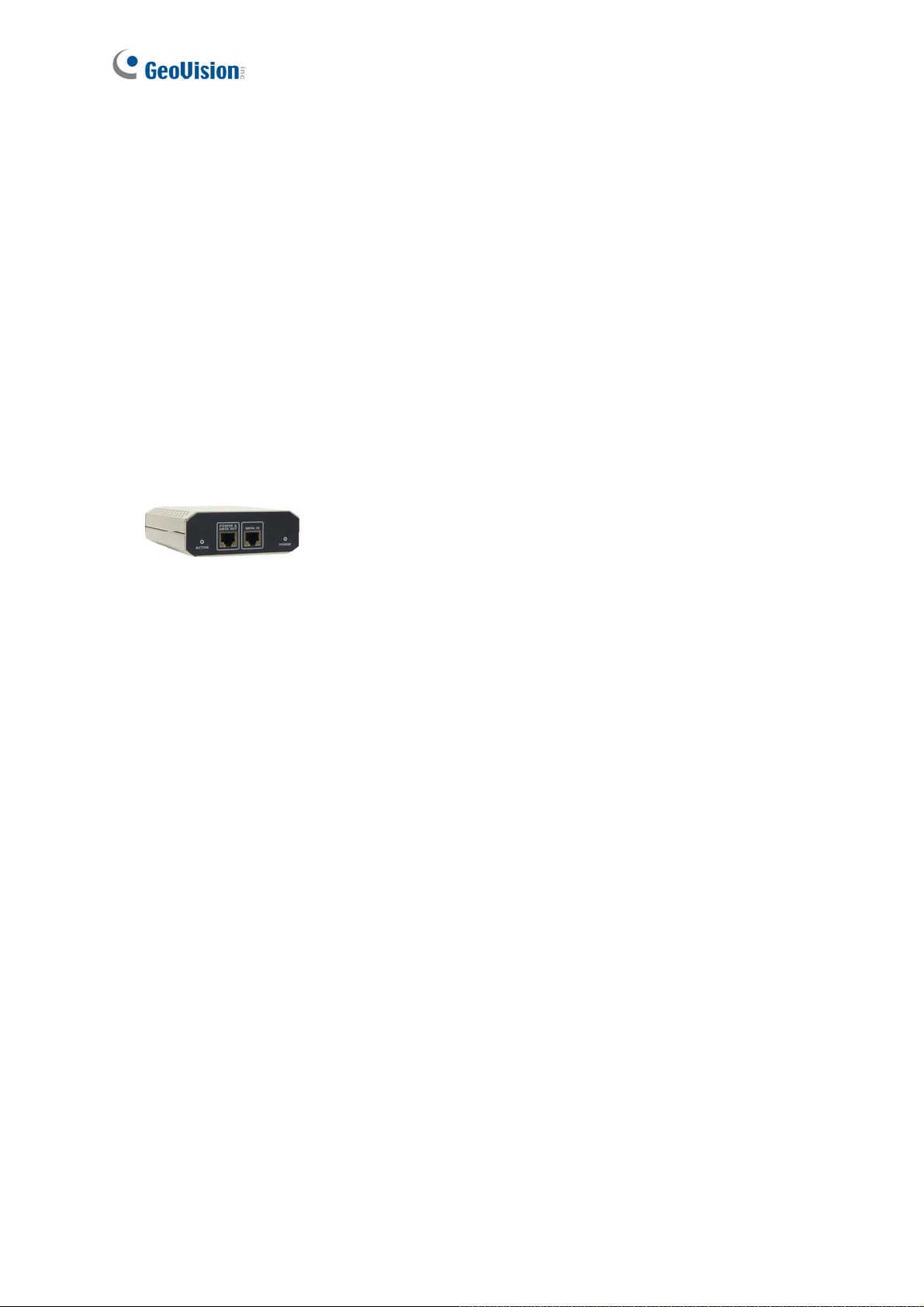
GV-PA191 PoE
Adapter
GV-Mount
Accessories
The GV-PA191 PoE adapter is designed to provide power and
network connection to the cameras over a single Ethernet cable. The
GV-PA191 PoE adapter is only available for GV-IP LPR Camera 5R.
The GV-Mount Accessories allows you to install GV-Hybrid LPR
Camera 10R / GV-IP LPR Camera 5R on the wall corner and pole.
For details, see Installing the Arctic Box Camera / Installing the Bullet
Camera, GV-Mount Accessories Installation Guide on the GV-IP LPR
Camera Software DVD.
Note for Connecting to GV-System
The GV-Hybrid LPR Camera 10R / GV-IP LPR Camera 5R is designed to work with and
record on GV-System, a hybrid or digital video management system.
Once the camera is connected to the GV-System, the resolution set on the GV-System will
override the resolution set on the camera’s Web interface. You can only change the resolution
settings through the Web interface when the connection to the GV-System is interrupted.
v
Page 8
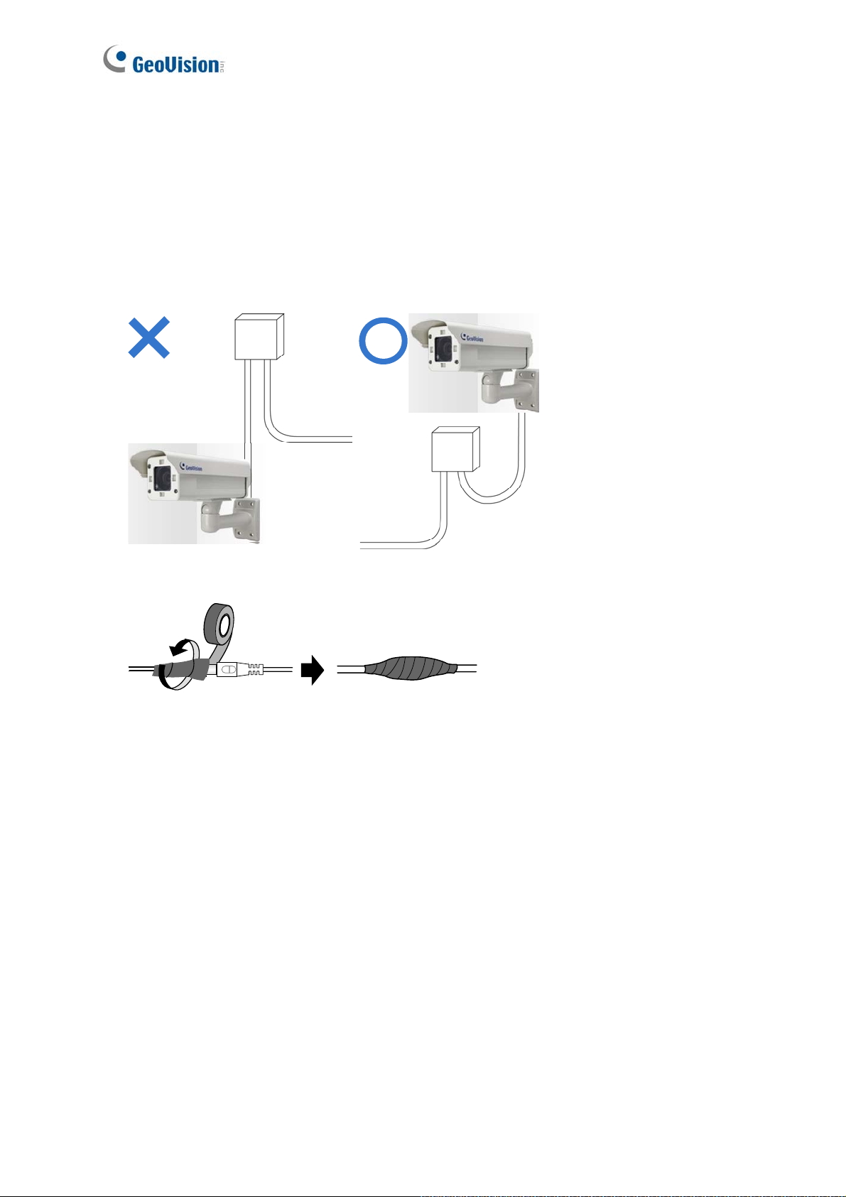
Note for Installing Camera Outdoor
When installing the GV-Hybrid LPR Camera 10R / GV-IP LPR Camera 5R outdoor, mind the
following:
1. Set the camera above the junction box to prevent water from entering the camera along
the cables.
2. Waterproof the PoE, power and TV-out cables with waterproof silicon rubber or the like.
3. To prevent the lens from fogging up, replace the silica gel bag every time you open the
camera, and conceal the gel bag in camera within 2 minutes of exposing to open air. The
silica gel bag loses it effectiveness when the dry camera is opened.
4. For each newly replaced silica gel bag, allow it to absorb moisture for at least 5 hours
before operating the camera.
5. The camera casing can be hot due to its IR LED. Make sure you unplug the power cable
and allow the camera casing to cool down before handling the camera.
vi
Page 9
Chapter 1 Introduction
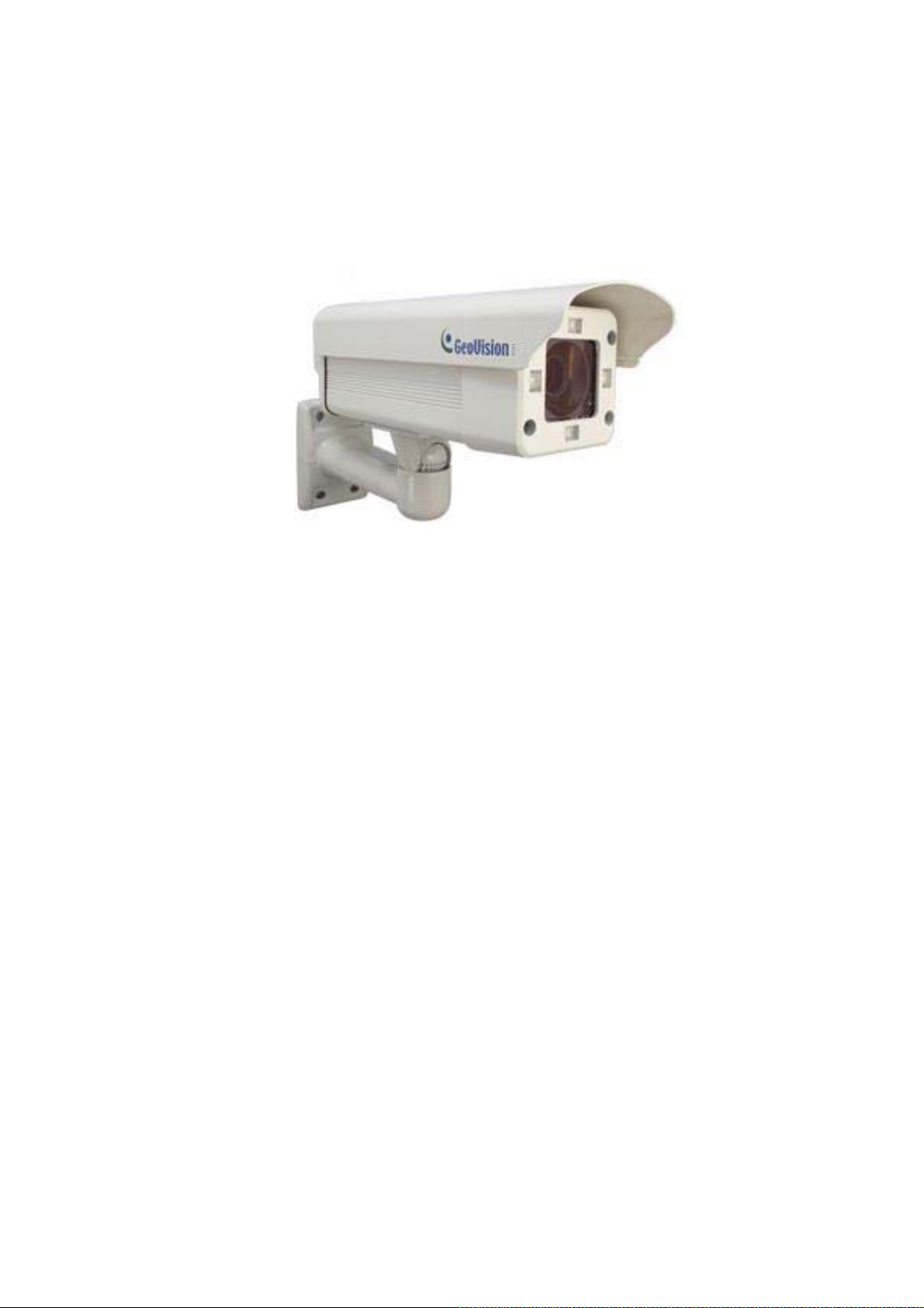
1.1 GV-Hybrid LPR Camera 10R
The GV-Hybrid LPR Camera 10R is a 1.3 MP B/W network camera designed solely for
recognition of reflective license plates on vehicles traveling at 120 km/hr (75 mph) or less.
With its high-power LEDs and intelligent IR, the camera is able to automatically adjust its
shutter speed to the scene and produce clear license plate capture under low-light conditions.
Under certain conditions, the GV-Hybrid Camera 10R can capture up to two lanes in a single
shot. It is also able to work in environments with extreme temperatures from as low as -40°C
(-40°F) up to 50°C (122°F).
The GV-Hybrid LPR Camera 10R can be easily configured through its Web interface and you
can record and play back recordings using the free GV-NVR software included in the standard
package.
Page 10

1.1.1 Features
1.3 megapixel B/W progressive scan CMOS
Dual streams from MJPEG or H.264
Up to 30 fps at 1280 x 1024
Recognition for reflective License Plate only
Maximum Speed 120 km/h (75 mph)
Ingress protection (IP67)
Vandal Resistance (IK10)
Built-in heater and fan
Support for TV-out
Two-way audio
Defog
Motion detection
Tampering alarm
Privacy mask
Text overlay
IP address filtering
Power supplied through PoE (IEEE 802.3 at)
Support for iPhone, iPad, Android and 3GPP
ONVIF (Profile S) conformant
31 languages on Web interface
2
Page 11

Introduction
1
1.1.2 System Requirements
To access the camera functions and settings through Web browser , ensure your PC is in good
network connection and use one of the following Web browsers:
Microsoft Internet Explorer 7.x or later
Google Chrome
Mozilla Firefox
Safari
Note:
1. For users of Internet Explorer 8 or later, additional settings are required. For details,
see Appendix C.
2. With non-IE browsers,
A. Motion Detection, Text Overlay, two-way audio and GPS map settings are not
supported.
B. The Play function is only available on the live view window (Figure 3-2).
C. RTSP streaming must be kept as enabled. For more details, see 4.3.8 RTSP /
3GPP.
3
Page 12
1.1.3 Packing List
GV-Hybrid LPR Camera 10R
Screw Anchor x 4
Screw x 4
Washer x 4
Big Torx Wrench
Small Torx Wrench
Sun-Shield Cover x 1
Silica Gel Bag x 2 (1 already installed)
Sticker x 2
GV-PA481 PoE Adapter
GV-PA481 Power Cord
GV-LPR Capture Dongle
GV-IP LPR Camera Software CD
GV-NVR Software DVD
GV-ASManager Software DVD
4
Page 13
Introduction
1
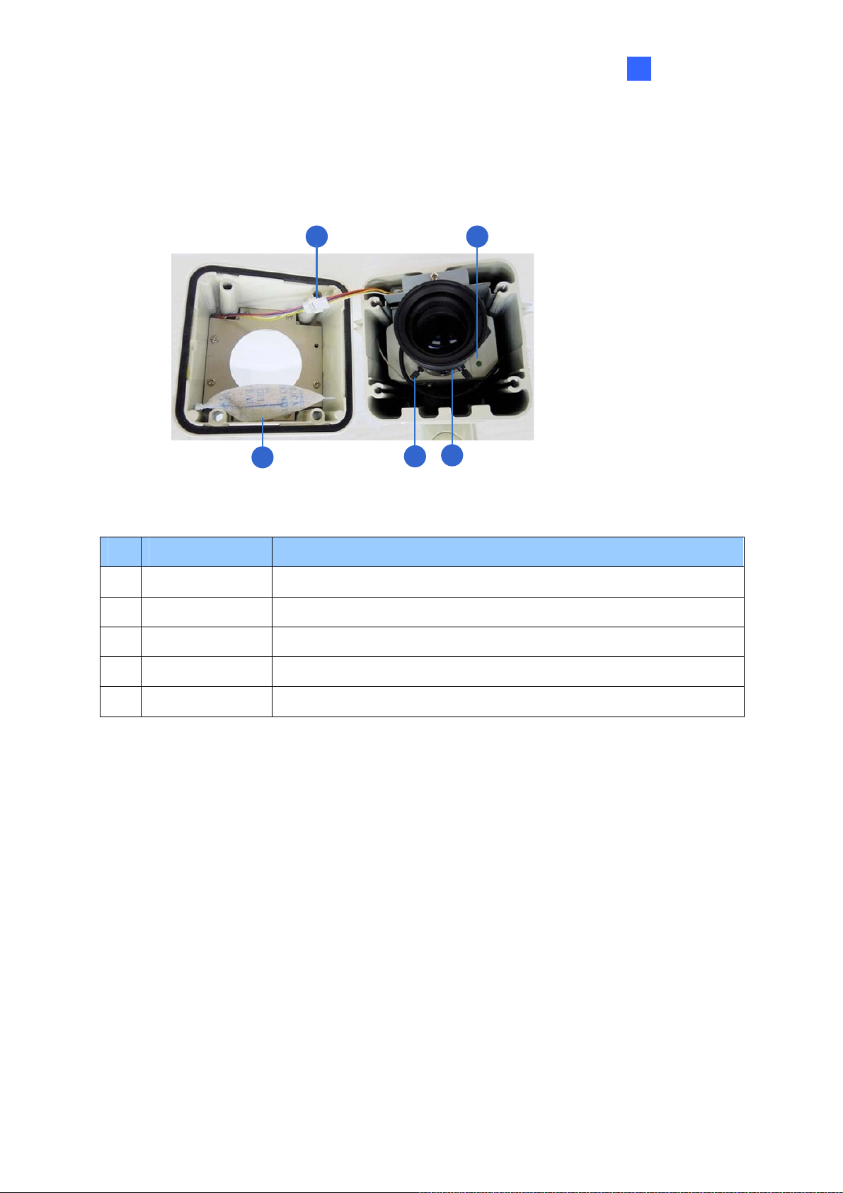
1.1.4 Overview
To access the functional panel of the GV-Hybrid LPR Camera 10R, follow the section below to
remove its camera cover first.
1 2
5
3
4
Figure 1-1
No. Name Description
1 IR power plug Supplies power to the built-in IR LEDs.
2 Status LED Turns on when the unit is ready for use.
3 Silica gel bag Keeps the camera housing dry.
4 Zoom Screw Adjusts the zoom of the camera.
5 Focus Screw Adjusts the focus of the camera.
5
Page 14
1.1.5 Device Installation
1.1.5.1 Installation Guidelines
To produce quality image and to avoid software recognition errors, make sure you adhere to
the guidelines when installing your GV-Hybrid LPR Camera 10R. See GV-LPR Camera
Installation Guide.
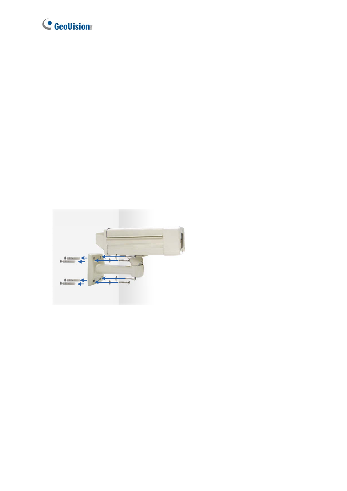
1.1.5.2 Installing the Camera
After you have read through the installation guides and chosen an installation site, follow the
steps below to install the GV-Hybrid LPR Camera 10R.
1. Mark the installation site and drill four holes for screw anchors.
2. Insert the supplied screw anchors.
3. Secure the camera to the wall using the supplied washers and screws.
Figure 1-2
4. Connect the camera to the network and supply power via the PoE cable. See 1.6
Connecting the Camera.
5. Access the live view. See 2.1 Accessing the Live View.
6
Page 15
Introduction
1
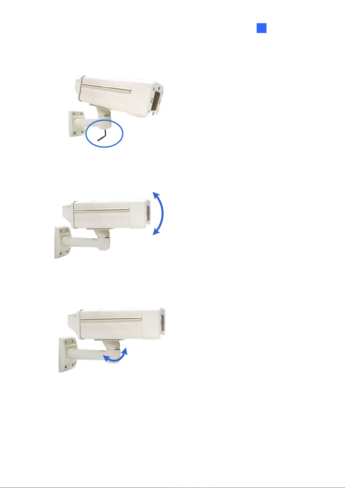
6. Based on the live view, adjust the angle of the camera. Loosen the indicated screw with
the supplied big torx wrench and adjust the joint.
Figure 1-3
Tilt Adjustment
Figure 1-4
Pan Adjustment
Figure 1-5
7
Page 16
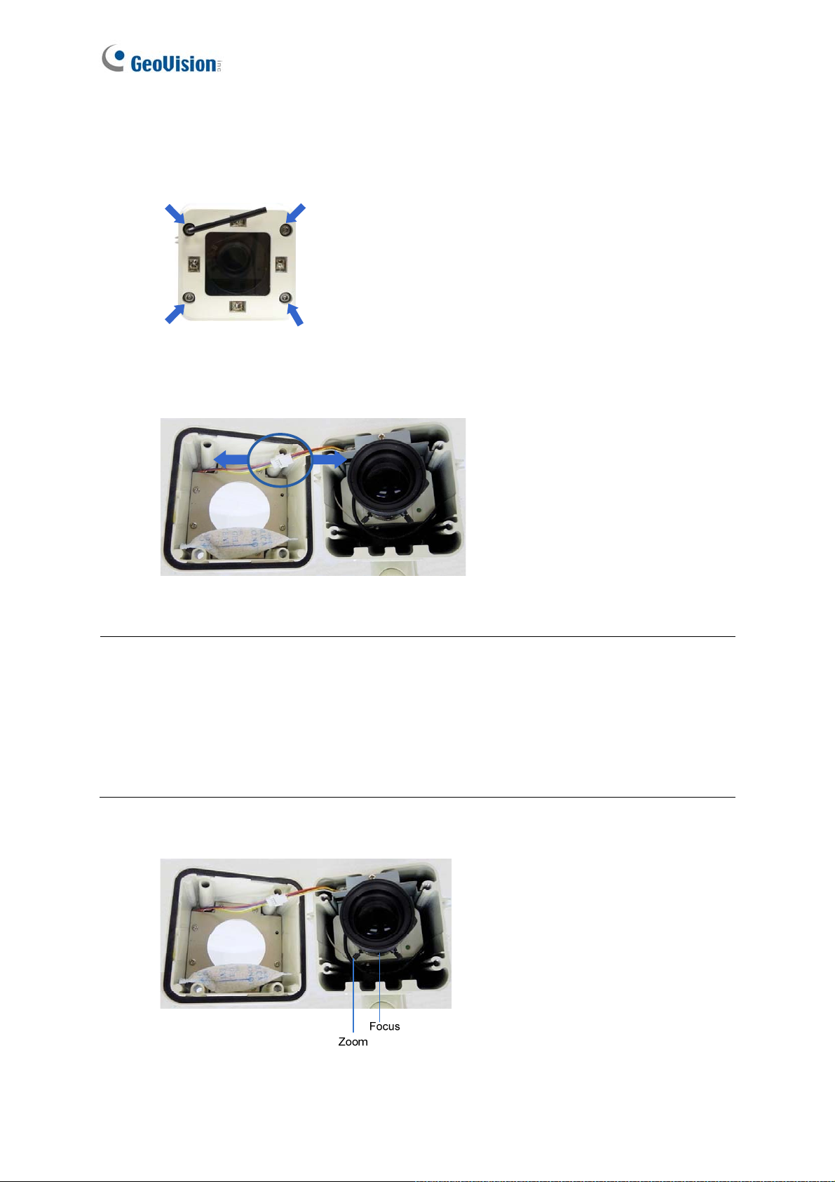
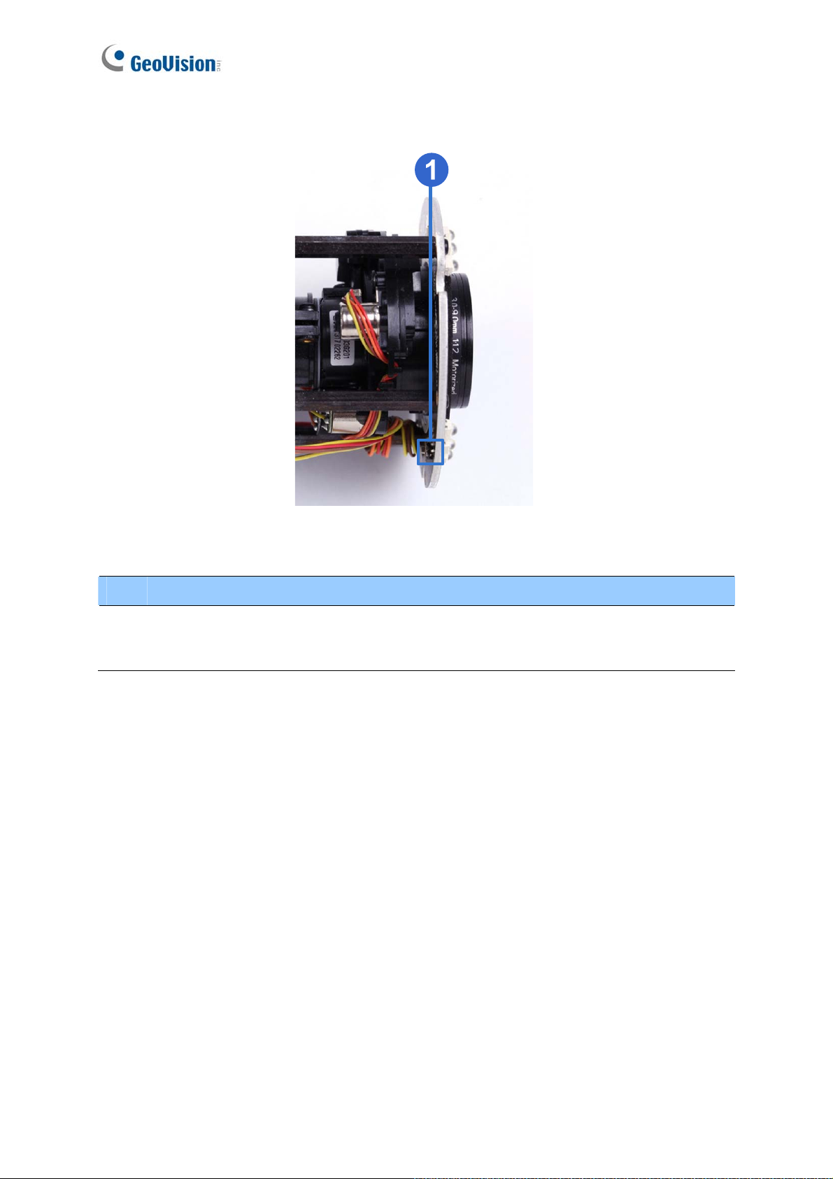
7. Based on the live view, adjust the focus and zoom of the camera.
A. Unscrew the cover with the supplied small torx wrench.
Figure 1-6
B. Hold the connectors and unplug them.
Figure 1-7
Important:
1. Unscrew and remove the cover carefully. Pulling the cover off may cause damages to
the inner wiring of the camera.
2. To prevent the live view from being darkened when the cover is removed, see LPR
Setting in 4.1.1 Video Setting.
C. Adjust the focus and zoom.
8
Figure 1-8
Page 17
Introduction
1
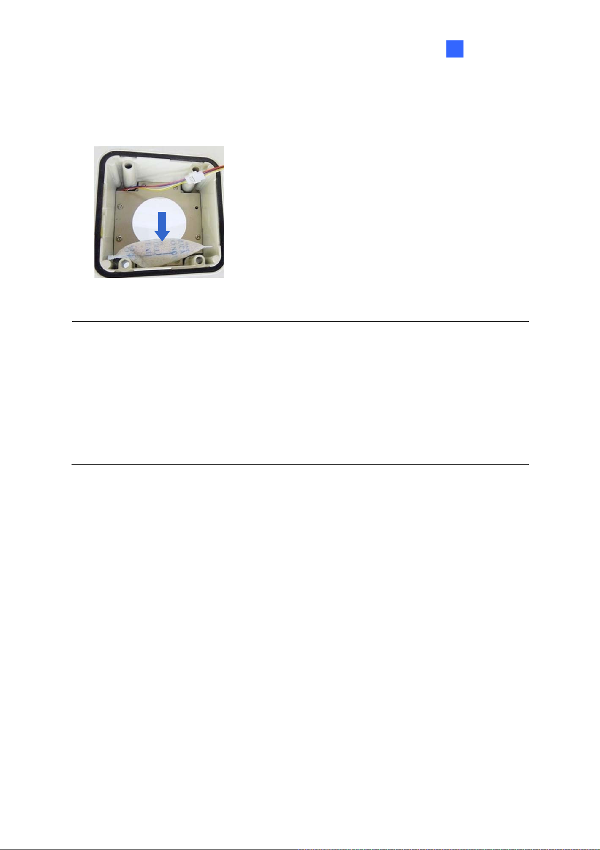
8. Replace the silica gel bag. Paste the sticker to the front side of the silica gel bag. Press
the sticker several times to make sure it adheres properly. Paste the silica gel bag to the
indicated place.
Figure 1-9
Important:
1. Be sure that the silica gel bag is concealed in the camera housing within 2 minutes of
exposing to open air.
2. To prevent the lens from fogging up, you must replace the silica gel bag every time you
open the camera. The gel bag loses its effectiveness when the dry camera is opened.
3. For each newly replaced silica gel bag, allow it to absorb moisture for at least 5 hours
before operating the camera.
9. Refer to step 7 to plug the connectors and secure the camera cover.
9
Page 18
1.1.6 Connecting the Camera
Follow the steps below to connect your GV-Hybrid LPR Camera 10R.
1. Optionally connect a speaker to the green RCA wire and an external microphone to the
pink RCA wire.
2. Optionally connect a monitor to the black BNC wire. Enable the TV-Out function by
selecting the correct signal format at the TV Out field on the Web interface. See 4.1.1
Video Settings.
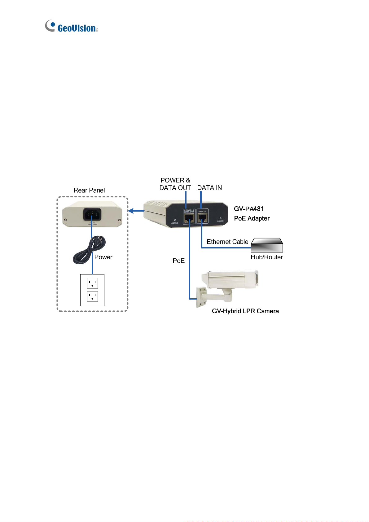
3. Connect the camera’s cable to the GV-PA481 PoE adapter as illustrated below. The
power and network will be supplied simultaneously.
Figure 1-10
4. When the status LED of the camera is on, .you are ready to access the live view, adjust
the image clarity and configure the basics. See Getting Started, Chapter 2.
10
Page 19
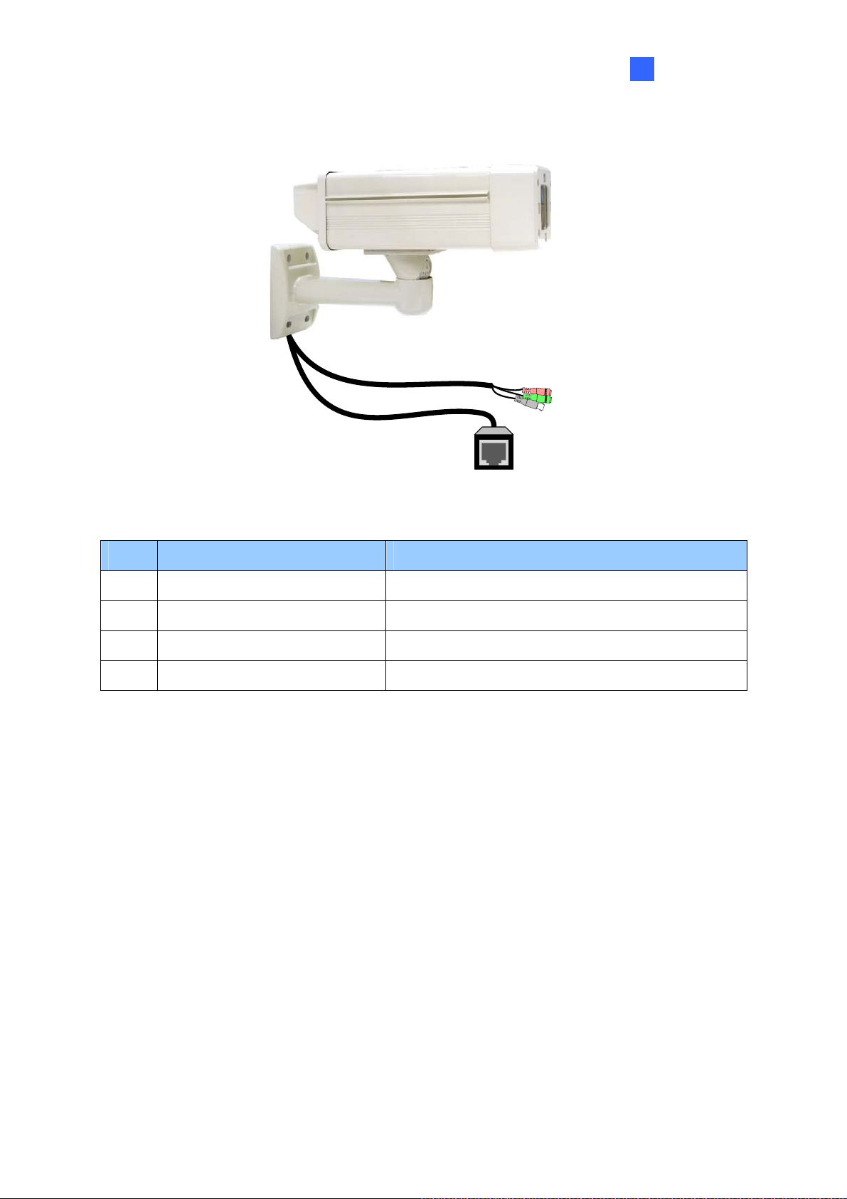
1.1.6.1 Wire Definition
Introduction
1
Figure 1-11
No. Wire Color Definition
1 Black (thick) PoE
2 Black BNC TV out
3 Green RCA Audio Out
4 Pink RCA Audio In
11
Page 20
1.2 GV-IP LPR Camera 5R
Ideal for parking lot installation, the GV-IP LPR Camera 5R is a 1.3 MP B/W network camera
designed for recognition of reflective license plates on vehicles traveling at 60 km/hr (37 mph)
or less. With its multiple LEDs and intelligent IR, the camera is able to automatically adjust its
shutter speed to the scene and produce clear license plate capture under low-light conditions.
The motorized varifocal lens take the advantage of its motorized focus / zoom in that the user
can remotely adjust the focus and zoom through the Web interface. It is weather proof (IP67)
and also able to work in environments with temperatures ranging from -10°C (14°F) to 50°C
(122°F).
The GV-IP LPR Camera 5R can be easily configured through its Web interface and you can
record and play back recordings using the free GV-NVR software included in the standard
package.
12
Page 21

1.2.1 Features
․ 1.3 megapixel B/W progressive scan CMOS
․ Motorized varifocal lens for remote focus / zoom adjustment
․ Dual streams from MJPEG or H.264
․ Up to 30 fps at 1280 x 1024
․ Maximum Speed 60 km/h (37 mph)
․ Recognition for reflective License Plate only
․ Ingress protection (IP67)
․ Vandal Resistance (IK10)
․ Built-In 12 IR LEDs
․ Built-in fan
Getting Started
2
․ Defog
․ Motion detection
․ Privacy mask
․ Text Overlay
․ IP address filtering
․ Power supplied through PoE (IEEE 802.3 at)
․ Support for iPhone, iPad, Android and 3GPP
․ ONVIF (Profile S) conformant
․ 31 languages on Web interface
13
Page 22

1.2.2 System Requirements
To access the camera functions and settings through Web browser , ensure your PC is in good
network connection and use one of the following Web browsers:
Microsoft Internet Explorer 7.x or later
Google Chrome
Mozilla Firefox
Safari
Note:
1. For users of Internet Explorer 8 or later, additional settings are required. For details,
see Appendix C.
2. With non-IE browsers,
A. Motion Detection, Text Overlay, two-way audio and GPS map settings are not
supported.
B. The Play function is only available on the live view window (Figure 3-2).
C. RTSP streaming must be kept as enabled. For more details, see 4.3.8 RTSP /
3GPP.
14
Page 23

1.2.3 Packing List
․ GV-IP LPR Camera 5R
․ Self Tapping Screw x 3
․ Plastic Screw Anchor x 3
․ Torx Wrench x 2
․ Sun-Shield Cover Kit (1 Sun-Shield Cover, 2 Philips Head Screws,
2 Plastic Screw Spacers and 2 Hexagon Screws included)
․ Silica Gel Bag x 2 (1 already installed)
․ GV-LPR Capture Dongle
․ GV-IP LPR Camera Software CD
․ GV-NVR Software DVD
Getting Started
2
․ GV-ASManager Software DVD
15
Page 24
1.2.4 Overview
No. Name Description
Resets all configurations of the GV-IP LPR Camera 5R to the
1 Default
default factory settings. See 5.3 Restoring to Factory Default
Settings.
Figure 1-12
16
Page 25
Getting Started
2
1.2.5 Device Installation
1.2.5.1 Installation Guidelines
To produce quality image and to avoid software recognition errors, make sure you adhere to the
guidelines when installing your GV-IP LPR Camera 5R. See GV-LPR Camera Installation Guide.
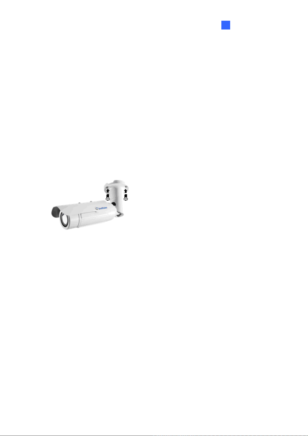
1.2.5.2 Installing the Camera
After you have read through the installation guides and chosen an installation site, follow the
steps below to install the GV-IP LPR Camera 5R.
1. Mark the installation site and drill three holes for screw anchors.
2. Insert the supplied screw anchors.
3. Secure the camera to the wall using the supplied screws.
Figure 1-13
4. Remove the protection sticker from the camera’s cover.
5. Connect the camera to the network and supply power via the PoE cable. See 1.2.6
Connecting the Camera.
6. Access the live view. See Chapter 2 Getting Started.
7. Based on the live view, adjust the angle, zoom and focus of the camera of the camera. For
adjusting three shafts, see 1.2.7 Adjusting the Angles.
Figure 1-12.
8. Install the sun-shield cover to the camera. For details, see 1.2.9 Installing the Sun-Shield Cover.
For changing zoom and focus, see
17
Page 26
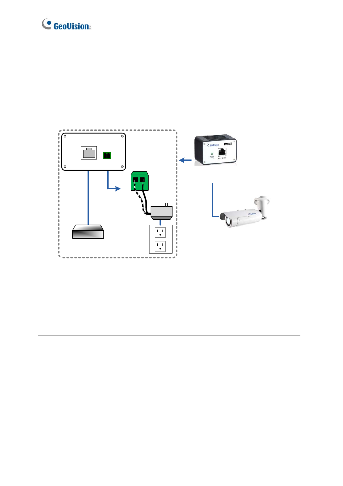
1.2.6 Connecting the Camera
It is suggested to use GV-PA191 PoE Adapter to connect the GV-IP LPR Camera 5R to the
network. Follow the steps below for connection.
1. Connect the camera’s cable to the GV-PA191 PoE Adapter as illustrated below. The
power and network will be supplied simultaneously.
Rear Panel
LAN 10/100
Ethernet
Cable
Hub/Router
Power IN
Power
(-)(+)
GV-PA191 PoE Adapter
PoE
GV-IP LPR Camera 5R
Figure 1-14
2. When the Power LED on the front panel of the GV-PA191 PoE Adapter turns green, you
are ready to access the live view, adjust the image clarity and configure the basics. See
Getting Started, Chapter 2.
Note: The GV-PA191 PoE Adapter (AC Power Adapter included) can be purchased upon
request.
18
Page 27
Getting Started
2
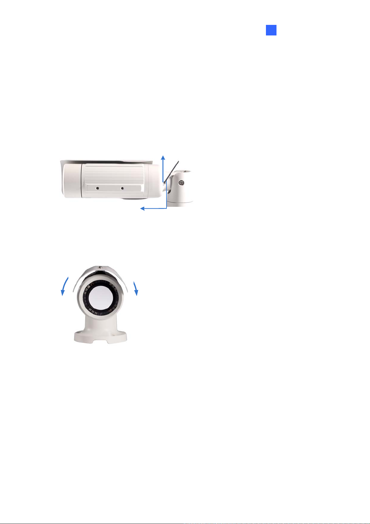
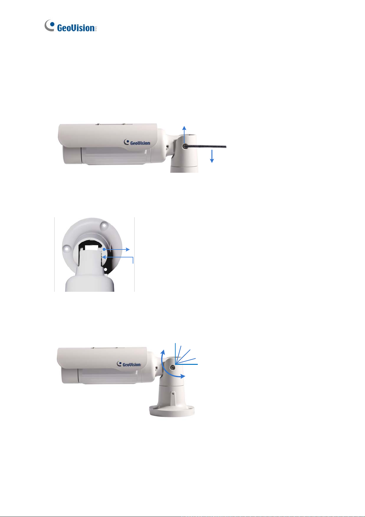
1.2.7 Adjusting the Angles
The GV-IP LPR Camera 5R is designed to be adjustable in three shafts for easy and flexible
installation.
First Shaft
You can adjust the camera body by 360 degrees to the right or the left.
1. Unscrew the panning lock screw with the torx wrench.
Panning Lock Screw
Torx Wrench
Figure 1-15
2. Adjust the angle of camera body to the right or the left, and fasten the panning lock screw.
0 ~ 360°
Figure 1-16
19
Page 28
Second Shaft
You can adjust the camera body up and down by 90, 112.5, 135, 157.5 or 180 degrees by using the
gears inside the camera body and the camera base.
1. Unscrew the tilting lock screw with the torx wrench.
Tilting Lock Screw
Torx Wrench
2. Hold the camera body, and move the camera base to the right to separate the camera
Figure 1-17
gears.
Move the Camera
Base to the Right
Camera Gears
Camera Body
Figure 1-18
3. Adjust the angle of camera body to 90°, 112.5°, 135°, 157.5° or 180°. Then move the
camera base to the left to combine the gears.
180
°
157.5°
135°
112.5°
90°
Figure 1-19
4. Fasten the tilting lock screw.
20
Page 29
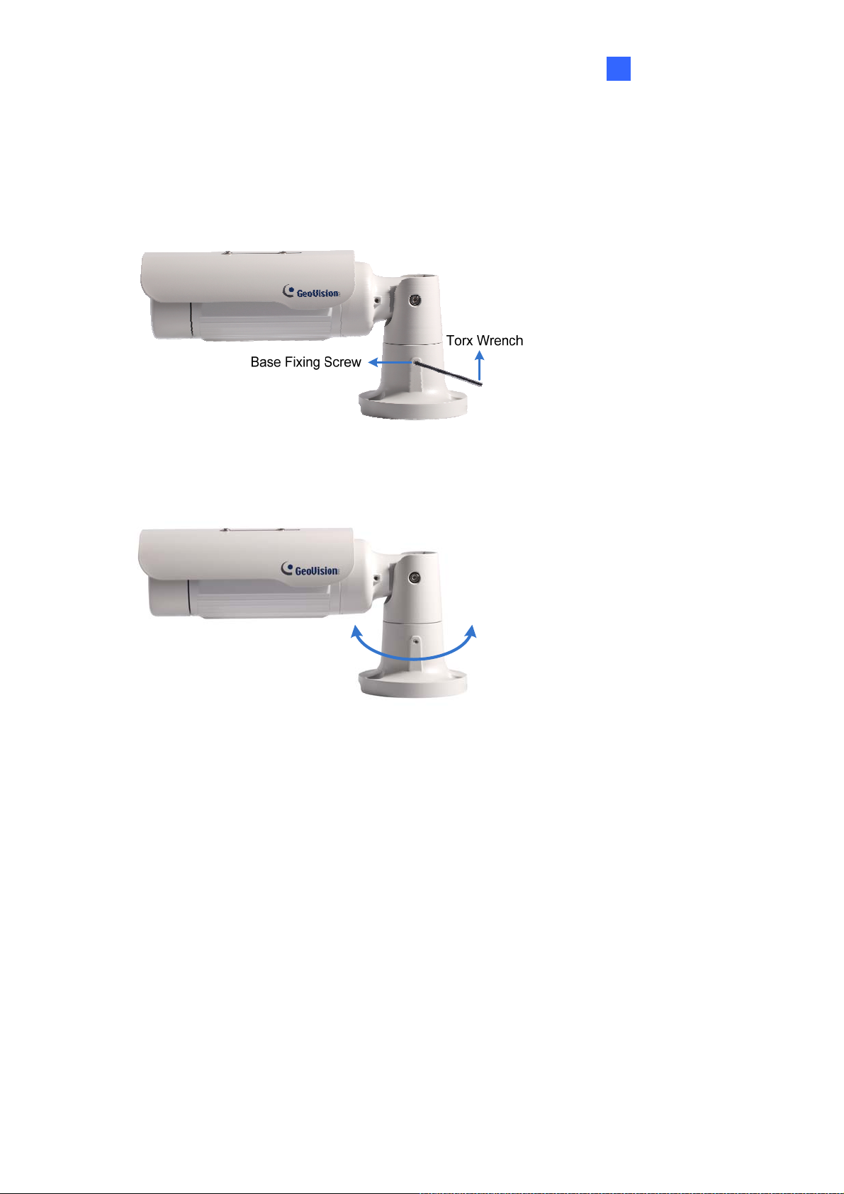
Third Shaft
You can adjust the camera base by 360°.
1. Unscrew the base fixing screw with the torx wrench.
Figure 1-20
Getting Started
2
2. Adjust the angle of camera base, and fasten the base fixing screw.
0~360°
Figure 1-21
21
Page 30
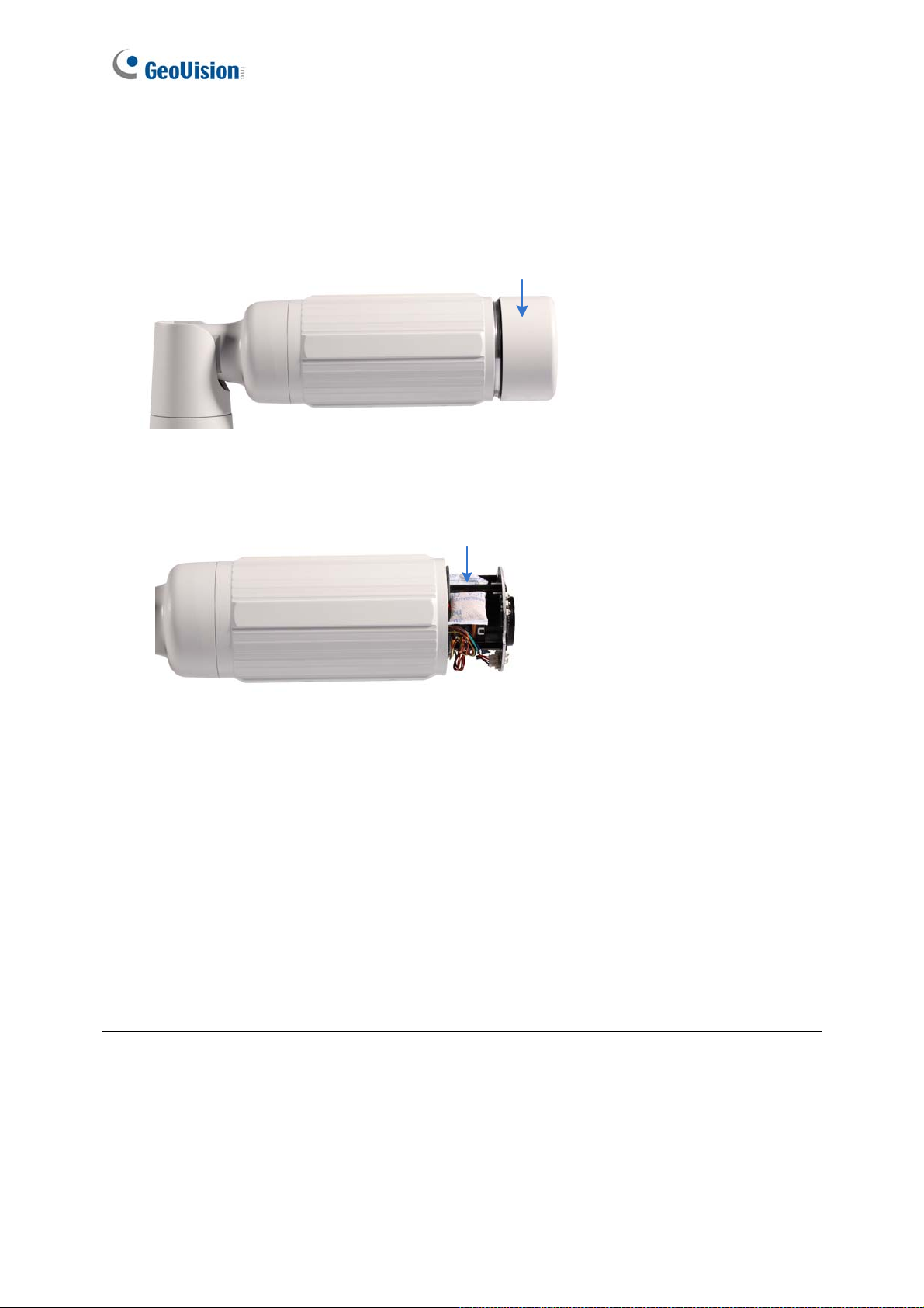
1.2.8 Replacing the Silica Gel Bag
To replace the original silica gel bag with a new one, follow the steps below.
1. Loosen the camera’s cover.
Camera’s Cover
Figure 1-22
2. Remove the silica gel bag.
Silica Gel Bag
Figure 1-23
3. Insert a new silica gel bag to the camera module and fasten the camera’s cover within 2
minutes of opening the silica gel bag package.
IMPORTANT:
1. The silica gel loses its effectiveness when the dry camera is opened. To prevent the lens
from fogging up, replace the silica gel bag every time when you open the camera and
conceal the gel bag in the camera within two minutes of exposing to the open air.
2. For each newly replaced silica gel bag, allow it to absorb moisture for at least 5 hours
before operating the camera.
22
Page 31

Getting Started
2
1.2.9 Installing the Sun-Shield Cover
After setting up the Bullet Camera, now you can install the sun-shield cover to the camera.
1. Fasten the hexagon screws either on top or below the camera.
Figure 1-24
2. Put the sun-shield cover on top of hexagon screws. Make sure to aim the rear hexagon
screw at the edge of the sun-shield cover’s aperture for optimal sun-shield performance.
Figure 1-25
3. Fasten the Philips head screws with the plastic screw spacers.
Figure 1-26
23
Page 32

Chapter 2 Getting Started
2.1 Looking Up the IP Address
By default, your GV-Hybrid LPR Camera 10R / GV-IP LPR Camera 5R is assigned with an
unused IP address by the DHCP server when the camera is connected to the network. This IP
address remains unchanged unless you unplug or disconnect your camera from the network.
Note: If your router does not support DHCP, the default IP address will be 192.168.0.10. In
this case, it is strongly suggested to modify the IP address to avoid IP address conflict with
other GeoVision IP device on the same LAN. To change the IP address, see Changing the IP
Address later in this section.
Follow the steps below to find out the IP address of your camera:
1. Install the GV-IP Device Utility program from the Software DVD.
Note: The PC installed with GV-IP Device Utility must be under the same LAN with the
camera you wish to configure.
2. On the PC desktop, select Start, point to Programs and select GV IP Device Utility to
execute the program. The GV-IP Device Utility window appears and automatically
searches for the GV-IP devices on the same LAN.
24
Figure 2-1
Page 33

3. Click the Name or Mac Address column to sort.
Figure 2-2
4. Find the Mac Address of the camera to see its IP address.
Getting Started
2
Changing the IP Address
To modify the static IP address or set the camera to a public dynamic IP address, log in the
Web interface to access the network setting page.
1. Open your Web browser, and type in the IP address.
For static network connection, type the default IP address http://192.168.0.10
For DHCP connection, follow steps in 2.1 Looking Up the IP Address to look up the
current IP address.
2. In both Login and Password fields, type the default value admin. Click Apply.
3. In the left menu, select Network and then LAN to begin the network settings. This page
appears.
Figure 2-3
25
Page 34

4. Select Static IP address or PPPoE and type the required network information.
5. Click Apply. The camera is now accessible by entering the assigned IP address on the
Web browser.
Important:
1. If your camera uses a public dynamic IP address via PPPoE, use the dynamic DNS
Service to obtain a domain name linked to the camera’s changing IP address first. For
details on Dynamic IP Address and PPPoE, see 4.5.2 Advanced TCP/IP and 4.5.1 LAN
Configuration.
2. If PPPoE is enabled and you cannot access the camera, you may have to reset it to the
factory default and then perform the network settings again. To restore the factory
settings, see 5.3 Restoring to Factory Default Settings.
26
Page 35

Getting Started
2
2.2 Accessing Your Surveillance Images
Follow these steps to access your surveillance images:
1. Open the Internet Explorer browser.
2. Enter the IP address or domain name of the GV-Hybrid LPR Camera 10R / GV-IP LPR
Camera 5R in the Location/Address field of your browser. To look up the IP address, see
2.1 Looking Up the IP Address.
Figure 2-4
3. Enter the login name and password. The administrator account has unrestricted access to
all the features and functions. The guest account is restricted to accessing live view and
network status information.
The default login name and password for Administrator are admin.
The default login name and password for Guest are guest.
4. A video image, similar to the example in Figure 3-1, is now displayed on your browser.
Note: To enable the updating of images in Microsoft Internet Explorer, you must set your
browser to allow ActiveX Controls and perform a once-only installation of GeoVision’s
ActiveX component onto your computer.
27
Page 36

2.3 Configuring the Basics
Once you have installed and logged in the GV-Hybrid LPR Camera 10R / GV-IP LPR Camera
5R, you are ready to configure some of its primary settings through the Web interface:
Date and time adjustment: see 4.6.1 Date and Time Settings.
Login and privileged passwords: see 4.6.4 User Account.
Network gateway: see 4.5 Network.
Camera image adjustment: see 3.2 The Control Panel of the Live View Window.
Video format, resolution and frame rate: see 4.1.1 Video Settings.
28
Page 37

Chapter 3 Guest Mode and Live View Panel
This section introduces the features of the guest mode and the Live View window.
Main Page of Guest Mode
Figure 3-1
Page 38

3.1 The Live View Window
In the left menu, click Live View, and then select Camera to see the live video.
Figure 3-2
No. Name Function
1 Play Plays live video.
2 Stop Stops playing video.
Talks to the surveillance area from the local computer. Note this
3 Microphone
function is not available for GV-IP LPR Camera 5R.
Listens to the audio around the camera. Note this function is not
4 Speaker
available for GV-IP LPR Camera 5R.
Takes a snapshot of live video.
5 Snapshot
--- See 3.3 Snapshot of a Live Video.
Records live video to the local computer.
6 File Save
--- See 3.4 Video Recording.
30
Page 39

No. Name Function
Switches to full screen view. Right-click the image to have these
3
Gusest Mode and Live View Panel
7 Full Screen
Show System
8
Menu
options: Snapshot, Full Screen, Resolution, PIP, PAP, GPS and
Google Maps.
--- See 3.5 Picture-in-Picture and Picture-and-Picture View.
Brings up these functions: Alarm Notify, Video and Audio
Configuration, Remote Config, Show Camera Name and
Image Enhance.
--- See 3.6 Alarm Notification, 3.7 Video and Audio Configuration,
3.8 Remote Configuration, 3.9 Camera Name Display and 3.10
Image Enhancement respectively.
31
Page 40

3.2 The Control Panel of the Live View Window
To open the control panel of the Live View window, click the arrow button on top of the viewer.
You can access the following functions by using the right and left arrow buttons on the control
panel.
Click the this button to select
from a drop-down menu
Click the this arrow button
to open the control panel
Arrow buttons
Figure 3-3
[Information] Displays the version of the GV-Hybrid LPR Camera 10R / GV-IP LPR Camera
5R, local time of the local computer, time of the camera, the number of users logging in to the
camera and the OCX registration path.
[Video] Displays the current video codec, resolution and data rate.
[Audio] Displays the audio data rates when the microphone and speaker devices are
enabled.
[Alarm Notify] Displays the captured images by motion detection. For this function to work,
you must configure the Alarm Notify settings first. See 3.6 Alarm Notification.
32
Page 41

3
Gusest Mode and Live View Panel
[Camera Adjustment] Adjust the image quality settings. Click Save to store the changes to
the settings.
Figure 3-4
Brightness: Adjust the brightness of the image.
Contrast: Adjust the relative differences between one pixel and the next.
Sharpness: Adjust the sharpness of the image.
Gamma: Adjust the relative proportions of bright and dark areas.
Image Orientation: Change the image orientation on the Live View window.
33
Page 42

Slowest Shutter Speed: Set the shutter speed. Shutter speed controls the amount of
the lights enters the image sensor and directly impacts the quality of image
presentation. A slow shutter speed allows higher light exposure that creates a brighter
overall image by blurring moving objects and bringing out background details, and a
faster shutter speed lowers color and image clarity in order to capture motions. The
minimum shutter speed ranges from 1/500 to 1/8000 sec. Select Auto for automatic
shutter control or select a shutter speed value.
Defog: Select Auto to automatically enhance the visibility of images. Select Close to
disable the function.
Zoom: Click the Zoom In and Zoom Out buttons to adjust the apparent
distance of the scene. Note this function is only available for GV-IP LPR Camera 5R.
Focus Change: Click the Focus In and Focus Out buttons to adjust the
focus. To focus automatically, click the Auto Focus
button. Note this function is
only available for GV-IP LPR Camera 5R.
Focus Mode: Select Normal Scan, Regional Scan or Full Scan and then click the
Start
button to automatically adjust the camera focus. The Normal Scan mode
focuses the camera the fastest. The Regional Scan mode focuses the area selected
on the live view. The Full Scan mode performs a detailed checkup and applies the
best focus. Note this function is only available for GV-IP LPR Camera 5R.
[GPS] Position the GV-Hybrid LPR Camera 10R / GV-IP LPR Camera 5R on Google maps.
For details, see 4.6.2 GPS Maps Settings.
[Internal Temperature] Shows the current internal temperature of the camera and the normal
temperature range.
[Download] Allows you to install programs from the hard drive.
34
Page 43

3
Gusest Mode and Live View Panel
3.3 Snapshot of a Live Video
To take a snapshot of live video, follow these steps:
1. Click the Snapshot button (No. 5, Figure 3-2). The Save As dialog box appears.
2. Specify Save in, type the File name, and select JPEG or BMP for Save as Type. You
may also choose to display the camera name and/or the date, the text color and image
quality for the snapshot.
3. Click the Save button to save the image in the local computer.
Note: You can also obtain a snapshot of the live view without logging in the user interface by
executing the CGI command. See Appendix A.
3.4 Video Recording
You can record live video for a certain period of time to your local computer.
1. Click the File Save button (No. 6, Figure 3-2). The Save As dialog box appears.
2. Specify Save in, type the File name, and move the Time Period scroll bar to specify the
time length of the video clip from 1 to 5 minutes.
3. Click the Save button to start recording.
4. To stop recording, click the Stop button (No. 2, Figure 3-2).
35
Page 44

3.5 Picture-in-Picture and Picture-and-Picture View
The Live View window provides two types of close-up views: Picture-in-Picture (PIP) and
Picture-and Picture (PAP). The two views are useful to provide clear and detailed images of
the surveillance area.
Picture-in-Picture View
With the Picture-in-Picture (PIP) view, you can crop the video to get a close-up view or zoom
in on the video.
Navigation box
Inset window
Figure 3-5
1. Right-click the live view and select PIP. An inset window appears.
2. Click the insert window. A navigation box appears.
3. Move the navigation box around in the inset window to have a close-up view of the
selected area.
4. To adjust the navigation box size, move the cursor to any of the box corners, and enlarge
or diminish the box.
5. To exit the PIP view, right-click the image and click PIP again.
36
Page 45

3
Gusest Mode and Live View Panel
Picture-and-Picture View
With the Picture-and-Picture (PAP) view, you can create a split video effect with multiple
close-up views on the image. A total of 7 close-up views can be defined.
Figure 3-6
1. Right-click the live view and select PAP. A row of three inset windows appears at the
bottom.
2. Draw a navigation box on the image, and this selected area is immediately reflected in
one inset window. Up to seven navigation boxes can be drawn on the image.
3. To adjust a navigation box size, move the cursor to any of the box corners, and enlarge or
diminish the box.
4. To move a navigation box to another area on the image, drag it to that area.
5. To add, display/hide or to change the frame color of the navigation boxes, right-click the
live view, select Mega Pixel Setting and click one of these options:
Enable Add-Focus-Area Mode: Allows the user to add navigation boxes to the
image.
Display Focus Area of PAP Mode: Displays or hides the navigation boxes on the
image
Set Color of Focus Area: Changes the color of the box frames.
6. To delete a navigation box, right-click the desired box, select Focus Area of PAP Mode
and click Delete.
7. To exit the PAP view, right-click the image and click PAP again.
37
Page 46

3.6 Alarm Notification
When a motion is detected, you can be alerted by a pop-up live video and view up to four
captured images.
Pop-up live video
Captured images
Figure 3-7
To configure this function, click the Show System Menu button (No. 8, Figure 3-2), and select
Alarm Notify. This dialog box appears.
Figure 3-8
Motion Notify: Once motion is detected, the captured images are displayed on the
control panel of the Live View window.
I/O Alarm Notify: This function is not available for GV-Hybrid LPR Camera 10R / GV-IP
LPR Camera 5R.
Alert Sound: Activates the computer alarm on motion.
Auto Snapshot: The snapshot of live video is taken every 5 seconds on motion.
File Path: Assigns a file path to save the snapshots.
38
Page 47

3
Gusest Mode and Live View Panel
3.7 Video and Audio Configuration
You can enable the microphone and speaker for two-way audio communication and adjust the
set the number of frames to keep for live view buffer.
Click the Show System Menu button (No. 8, Figure 3-2), and select Video and Audio
Configuration.
Camera: Sets the number of frames to keep in live view buffer. Keeping more frames for
live view buffer can ensure a smooth live view, but the live view will be delayed for the
number of seconds specified.
Figure 3-9
Audio Configure: You can enable the microphone and speaker and adjust the audio
volume. Note this setting is not available for GV-IP LPR Camera 5R.
Figure 3-10
39
Page 48

3.8 Remote Configuration
You can upgrade the device firmware over the network. Click the Show System Menu button
(No. 8, Figure 3-2), and select Remote Config. The Remote Config dialog box will appear.
[Firmware Upgrade] In this tab, you can upgrade the firmware over the network. For details,
see Chapter 5 Advanced Applications.
3.9 Camera Name Display
To display the camera name on the image, click the Show System Menu button (No. 8,
Figure 3-2), and select Show Camera Name.
3.10 Image Enhancement
To enhance the image quality of live video, click the Show System Menu button (No. 8,
Figure 3-2), and select Image Enhance. This dialog box appears.
Figure 3-11
De-Interlace: Covert the interlaced video into non-interlaced video.
De-Block: Remove the block-like artifacts from low-quality and highly compressed video.
Enable DirectDraw: Activate the DirectDraw function.
40
Page 49

Chapter 4 Administrator Mode
The Administrator can access and configure the GV-Hybrid LPR Camera 10R / GV-IP LPR
Camera 5R over the network. The configuration categories include: Video and Motion,
Events and Alerts, Monitoring, Recording Schedule, Remote ViewLog, Network, and
Management.
Figure 4-1
Page 50

Corresponding Section for Configuration Menu
Find the topic of interest by referring to the indicated section.
4.1.1 Video Settings
4.1.2 Motion Detection
4.1 Video and Motion
4.2 Events and Alerts
4.3 Monitoring
4.4 Recording Schedule 4.4.1 Recording Schedule Settings
4.5 Network
4.1.3 Privacy Mask
4.1.4 Text Overlay
4.1.5 Tampering Alarm
4.2.1 Email
4.2.2 FTP
4.2.3 Center V2
4.2.4 VSM
4.2.5 Backup Center
4.2.5 GV-Video Gateway / GV-Recording Server
4.2.6 RTSP
4.5.1 LAN
4.5.2 Advanced TCP/IP
4.5.3 IP Filter
4.5.4 SNMP Settings
4.6 Management
4.6.1 Date and Time Settings
4.6.2 GPS Maps Settings
4.6.3 Storage Settings
4.6.4 User Account
4.6.5 Log Information
4.6.6 System Log
4.6.7 Tools
4.6.8 Language
42
Page 51

4
Administrator Mode
4.1 Video & Motion
The GV-Hybrid LPR Camera 10R / GV-IP LPR Camera 5R supports dual streams, Streaming
1 and Streaming 2, which allow separate codec and resolutions settings for a single video
transmission. In a bandwidth-limited network, such as mobile phone surveillance, this
dual-stream feature allows you to view live video in lower resolution and codec (Streaming 2),
and record in highest resolution 1280 x 1024 and codec MJPEG (Streaming 1) at the same
time.
Comparison between Stream 1 and Stream 2:
Video Setting Options Stream 1 Stream 2
Video Signal Type
Watermark Setting
Audio Codec
TV Out Setting
Status LED Control
Different codec, resolutions and frame rates can be applied to
Stream 1 and 2.
Not configurable. Settings in
Yes
Stream 1 will be automatically
applied to Stream 2.
43
Page 52

4.1.1 Video Settings
44
Figure 4-2A
Page 53

4
Administrator Mode
Figure 4-2B
[Name]
Rename the camera. The camera name will appear on the Live View. To display the camera
name, see 3.9 Camera Name Display.
45
Page 54

[Connection Template]
Select the type of your network connection. Unless you select Customized, this option will
automatically bring up the recommended video resolution, frame rate, bandwidth and GOP
size.
[Video Signal Type]
Select the codec type, resolution and frame rate. The default codec is MJPEG. Choose H.264
or MJPEG for the main stream/sub stream. The supported resolutions are listed blow:
Video Resolution
4:3
Main Stream
Sub Stream
[Bandwidth Management]
When using the H.264 codec, it is possible to configure the bitrate settings to control
bandwidth usage.
VBR (Variable Bitrate): The quality of the video stream is kept as constant as possible at
the cost of a varying bitrate. The bandwidth is much more efficiently used than a
comparable CBR. Set the image quality to one of the 5 standards: Standard, Fair, Good,
Great and Excellent.
Maximal Bit Rate: When the system bitrate exceeds the specified Maximal Bit Rate, the
16.9
5:4
4:3
16.9
5:4
1280 x 960, 640 x 480, 320 x 240
1280 x 720, 640 x 360, 448 x 252
1280 x 1024, 640 x 512, 320 x 256
640 x 480, 320 x 240
640 x 360, 448 x 252
640 x 512, 320 x 256
system will automatically lower its bitrate so as not to exceed it. Select one of the bitrates
from the drop-down list or select Auto if you do not want to enable this function. The
default value is 6 MB
CBR (Constant Bitrate): CBR is used to achieve a specific bitrate by varying the quality
of the stream. The bitrates available for selection depend on the image resolution.
[GOP Structure and Length]
Set the maximum number of seconds between every key frame.
46
Page 55

4
Administrator Mode
[Video Slice Mode]
Select Single Slice if the camera is displayed on a third-party NVR/DVR software and the live
view is incomplete or broken. The default is Auto.
[Record Settings]
Note this function is not available for GV-Hybrid LPR Camera 10R. The alarm settings allow
you to capture images before and/or after the motion happens.
Pre-alarm recording time: Activate video recording before an event occurs. Set the
recording time to 1 or 2 seconds. The recording is saved in the buffer of the camera.
Post-alarm recording time: Activate video recording onto the inserted memory card
after an event occurs. Set the recording time from 1 to 30 seconds.
Split interval: Set the maximum time length of each recorded file from 1 to 5 minutes.
Continue recording to the local storage when live view is accessed: Select this
function for continuous recording to the memory card even when the live view is
accessed through the Web interface or other software. This option is enabled by default.
[Text Overlay Settings]
Overlaid with camera name: Include camera names on live and recorded videos.
Overlaid with date stamps: Include date stamps on live and recorded videos.
Overlaid with time stamps: Include time stamps on live and recorded videos.
[Watermark Setting]
Enable this option to watermark all recordings. The watermark allows you to verify whether
the video has been tampered while it was recorded. See 5.4 Verifying Watermark.
[TV Out]
Select the signal format for the video output of the camera as either NTSC or PAL. This
function is disabled by default. Note this function is not available for GV-IP LPR Camera 5R.
Note: For smooth live view display on TV monitor, the video resolution must be of 1280 x
1024 or lower. If dual streams are enabled, the sub stream must be set at 640 x 480.
47
Page 56

[LED Control]
Ready LED: Select Disable if you do not wish to use the Status LED. Note this function is
not available for GV-IP LPR Camera 5R.
[LPR Setting]
Setup Mode: Select Enable to keep the brightness of the live view when the camera’s
cover is removed for focus adjustment. This function can prevent the live view from being
darkened when the camera’s cover with infrared illuminator is uninstalled. Note this
function is not available for GV-IP LPR Camera 5R.
Note: When this function is enabled, the text of “Setup Mode” will be overlaid on the live
view.
48
Page 57

4
Administrator Mode
4.1.2 Motion Detection
Motion detection is used to generate an alarm whenever movement occurs within the scene.
You can configure up to 8 detection zones with different sensitivity values. Create at least one
detection zone to enable this function.
Figure 4-3
1. Select a sensitivity value using the slider bar. There are 10 sensitivity levels. The higher
the value, the more sensitive the camera is to motion. The default sensitivity value is 9.
2. Define a detection zone by dragging an area on the image. Click Add when you are
prompted to confirm the setting.
3. To create several areas with different sensitivity values, repeat Steps 1 and 2.
4. Click Save to save the above settings.
5. Click Reset to clear all the selected areas.
6. For the camera to ignore environmental changes such as rain or snow, select the Ignore
environmental changes.
7. To reduce video noise when the lighting condition changes, select Noise Tolerance.
8. Click the Apply button.
49
Page 58

4.1.3 Privacy Mask
The Privacy Mask can block out sensitive areas from view , covering the areas with dark boxes
in both live view and recorded clips. This feature is ideal for privacy protection on locations
with private information, keyboard sequences (e.g. passwords), and any place you would like
to keep inaccessible to view.
Figure 4-4
1. Select the Enable option.
2. Drag the area(s) where you want to block out on the image. Click Add when you are
prompted to confirm the setting.
3. Click the Save button to save all the settings.
50
Page 59

4
Administrator Mode
4.1.4 Text Overlay
The Text Overlay allows you to overlay any text in any place on the camera view. Up to 16 text
messages can be created on one camera view. The overlaid text will be saved in the
recordings.
Figure 4-5
1. Select the Enable option.
2. Click Set Font to set up the font, font style and font size in a pop-up window.
3. Click any place on the image. This dialog box appears.
Figure 4-6
4. Type the desired text, and click OK. The text is overlaid on the image.
5. Drag the overlaid text to a desired place on the image.
6. Click Set Font to modify the font settings.
7. Click Save to apply the settings, or click Load (Undo) to revert to the last saved setting.
8. Click Preview to see how the text will appear on the image. Click Close to end the
preview.
51
Page 60

4.1.5 Tampering Alarm
Note this function is not available for GV-IP LPR Camera 5R.
The Tampering Alarm is used to detect whether a camera is being physically tampered. An e-mail
alarm can be sent when the camera is moved, covered up, or out of focus. Make sure the e-mail
settings are set up. For detail, see 4.2.1 E-Mail.
Figure 4-7
To configure the tampering alarm:
1. Select the Enable option.
2. If you want the camera to ignore any movement or scene change in certain areas, click
the
3. Select the desired detection sensitivity by moving the slider. The higher the value, the
more sensitive the camera is to scene changes.
4. In the Tolerance Time of Alarm field, specify the time length allowed for scene changes
before an e-mail notification is sent.
52
button to drag areas on the camera view.
Page 61

4
Administrator Mode
5. To trigger an alarm when the scene turns dark, e.g. the lens of camera has been covered,
select Alarm for Dark Images.
6. Click Apply to save all the settings.
53
Page 62

4.2 Events & Alerts
For motion and tampering events, the Administrator can set up two types of alert:
1. Send a captured image by e-mail or FTP. See 4.2.1 E-Mail and 4.2.2 FTP.
2. Notify Center Monitoring Stations such as Center V2, VSM, by video or text
alerts.
To enable above alerts, you must also set the following features:
Motion Detection (See 3.1.2 Motion Detection)
For e-mail and FTP alerts, it is required to start monitoring (See 4.3 Monitoring).
54
Page 63

4
Administrator Mode
4.2.1 E-mail
When a motion is detected, the GV-Hybrid LPR Camera 10R / GV-IP LPR Camera 5R can
send an e-mail alert, containing a captured image to a remote user.
Important: To send e-mail alert upon motion / tampering events, make sure you also enable
the Motion Detection / Tampering Alarm function. For setup details, see 3.1.2 Motion
Detection and 3.1.5 Tampering Alarm.
Figure 4-8
To enable the e-mail functions:
1. Select Enable to set up e-mail notifications.
2. Server URL/IP Address: Type the SMTP Server’s URL address or IP address.
3. Server Port: Type the SMTP Server’s port number or keep the default value 25.
4. From email address: Type the sender’s e-mail address.
5. Send to: Type the e-mail address(s) you want to send alerts to.
55
Page 64

6. Alerts interval time in minute: Specify the interval between e-mail alerts. The valid
interval is from 0 to 60 minutes. This option is useful for frequent event occurrence. Any
event detected during the interval period will be ignored.
7. If the SMTP Server needs authentication, select Need authentication to login and
type a valid Username and Password to log in the SMTP server. If the SMTP Server
needs a secure connection (SSL), select This server requires a secure connection.
8. Email-Alarm Settings: Select the event to automatically send an e-mail alert. Note the
Tampering Alarm option is not available for GV-IP LPR Camera 5R.
9. Click Apply.
10. In the left menu, select Monitoring and click the Start button to start monitoring.
56
Page 65

4
Administrator Mode
4.2.2 FTP
You can also send the captured image to a remote FTP server for alerts.
Important: To send FTP alert upon motions, be sure to set up the detection area on the
Motion Detection page. For details, see 4.1.2 Motion Detection.
Figure 4-9
[Upload to a FTP server]
1. Select Enable to set up the FTP function.
2. Server URL/IP Address: Type the URL address or IP address of the FTP Server.
3. Server Port: Type the port number of the FTP Server or keep the default value 21.
4. Type the Username and Password of the FTP Server.
5. Remote Directory: Type the name of the storage folder on the FTP Server.
57
Page 66

6. Alerts interval time in minute: Specify the interval between FTP alerts. The interval
can be between 0 and 60 minutes. The option is useful for frequent event occurrence.
Any event triggers during the interval period will be ignored.
7. FTP-Alarm Settings: Select Motion Detection to automatically send a snapshot to the
FTP Server upon motion detection. Select Continuously send images upon trigger
events (Motion) to upload a series of snapshots to the FTP Server upon motion
detection.
8. In the left menu, select Monitoring and click the Start button to start monitoring.
[Act as FTP server]
1. Enable FTP access to the GV-IP Cam: Select to allow the camera to act as an FTP
server for users to download AVI files.
2. Use alternative port: The default port is set to 21.
58
Page 67

4
Administrator Mode
4.2.3 Center V2
The central monitoring station Center V2 can be notified of a motion event by live videos and
text alerts. Up to two Center V2 servers can be connected. For live monitoring through Center
V2, you must already have a subscriber account on each of the Center V2 server.
Important: To notify the Center V2 Server upon motion events, be sure to set up the
detection area on the Motion Detection page. For details, see 4.1.2 Motion Detection and 7.1
Center V2.
Figure 4-10
59
Page 68

To enable the Center V2 connection:
1. Activate Link: Enable the monitoring through Center V2.
2. Host Name or IP Address: Type the host name or IP address of Center V2.
3. Port Number: Match the port to Port 2 on Center V2. Or keep the default value 5551. For
details, see 8.1 Center V2.
4. User Name: Type a valid user name to log in to Center V2.
5. Password: Type a valid password to log in to Center V2.
6. Click Apply. The Connection Status should display “Connected” and connected time.
7. To establish connection to the second Center V2, click the Connection 2 tab and repeat
the above steps for setup.
You can also find on this Center V2 settings page:
Cease motion detection messages from: Stops notifying Center V2 of motion detection.
Enable schedule mode: Starts the monitoring through Center V2 based on the schedule
you set in the Select Schedule Time section.
[Select schedule time]
Span 1- Span 3: Enable recording (upon motion events) at up to 3 different time frames
for a day, represented by Span 1 to Span 3.
Weekend: Enable recording (upon motion events) for both Saturday and Sunday or for
Sunday only.
60
Page 69

4
Administrator Mode
4.2.4 VSM
The central monitoring station VSM can be notified of a motion event by text alerts. Up to two
VSM servers can be connected. For live monitoring through VSM, you must already have a
subscriber account on each of the VSM server.
Important: To notify the VSM upon motions, be sure to set up the detection area on the
Motion Detection page. For details, see 4.1.2 Motion Detection and 7.2 VSM.
Figure 4-11
61
Page 70

To enable the VSM connection:
1. Activate Link: Enable the monitoring through VSM.
2. Host Name or IP Address: Type the host name or IP address of VSM.
3. Port Number: Match the port to Port 2 on VSM or keep the default value 5609. For
details, see 7.2 VSM.
4. User Name: Type a valid user name to log into VSM.
5. Password: Type a valid password to log into VSM.
6. Click Apply. The Connection Status should display “Connected” and connected time.
7. To establish connection to the second VSM, click the Connection 2 tab and repeat the
above steps for setup.
These options you can also find on this VSM setting page:
Cease motion detection messages from: Stops notifying VSM of motion detection.
Enable schedule mode: Starts the monitoring through VSM based on the schedule you
set in the Select Schedule Time section. For schedule setup, refer to 4.2.3 Center V2.
62
Page 71

4
Administrator Mode
4.2.5 Backup Center
Note this function is not available for GV-Hybrid LPR Camera 10R.
The connection to the GV-Backup Center allows you to back up another copy of recordings
and system log to the GV-Backup Center on an offsite location while the camera is saving
these data to the memory card. The GV-Backup Center provides a PC-based storage and
backup solution. For details on the GV-Backup Center, see GV-Backup Center User’s
Manual.
Important: This function is currently not supported in GV-IP LPR Camera 5R.
Figure 4-12
To enable connection to GV-Backup Center:
1. Activate Link: Enable the connection to the GV-Backup Center.
2. Host Name or IP Address: Type the host name or IP address of the GV-Backup Center.
63
Page 72

3. Port Number: Match the communication port on the GV-Backup Center or keep the
default value 30000.
4. User Name: Type a valid user name to log into the GV-Backup Center.
5. Password: Type a valid password to log into the GV-Backup Center.
6. Backup Video: Select the streams to back up their recordings to the GV-Backup Center.
7. Compact Video: Select the streams to only back up their Key Frames to the GV-Backup
Center, instead of full recordings. This option is useful to save the backup time.
8. Resend all files: Select this option to send all the recorded files that have received by the
Backup Center again.
9. Enable Schedule Mode: Enable the GV-Backup Center connection on the schedule you
set in the Select Schedule Time section. Refer to 4.4 Recording Schedule for the same
settings.
10. Click Apply. The Connection Status should display “Connected” and connected time.
If you have a failover GV-Backup Center server which provides uninterrupted backup services
in case the first GV-Backup Center failed, configure the failover GV-Backup Center as below.
1. Automatic Failover Support: Enable the automatic connection to the failover GV-Backup
Center once the connection between camera and the first GV-Backup Center is
interrupted.
2. Host Name or IP Address: Type the host name or IP address of the failover GV-Backup
Center.
3. Port Number: Match the communication port on the failover GV-Backup Center or keep
the default value 30000.
4. User Name: Type a valid user name to log into the failover GV-Backup Center.
5. Password: Type a valid password to log into the failover GV-Backup Center.
6. Click Apply.
64
Page 73

4
Administrator Mode
4.2.6 GV-Video Gateway / GV-Recording Server
The GV-Video Gateway and GV-Recording Server are video streaming servers designed for
large-scale video surveillance deployments. The GV-Video Gateway / GV-Recording Server
(with recording capability) can receive up to 128 channels from various IP video devices, and
distribute up to 300 channels to its clients. With the GV-Video Gateway / GV-Recording
Server, the desired frame rate can be ensured while the CPU loading and bandwidth usage of
the IP video devices are significantly reduced.
The GV-Hybrid LPR Camera 10R / GV-IP LPR Camera 5R can be connected with up to two
GV-Video Gateway / GV-Recording Server. To send the video images to the GV-Video
Gateway or GV-Recording Server, you must already have an account on each of the
GV-Video Gateway / GV-Recording Server with the user name and password specified
below.
Figure 4-13
65
Page 74

To enable connection to GV-Video Gateway / GV-Recording Server:
1. Activate Link: Enable the monitoring through GV-Video Gateway / GV-Recording Server.
2. Host Name or IP Address: Type the host name or IP address of the GV-Video Gateway /
GV-Recording Server.
3. Port Number: Match the communication port specified on GV-Video Gateway /
GV-Recording Server. Or keep the default value 50000.
4. User Name: Type a valid user name to log into GV-Video Gateway / GV-Recording
Server.
5. Password: Type a valid password to log into GV-Video Gateway / GV-Recording Server.
6. Click Apply. The Connection Status should display “Connected” and connected time.
7. To establish connection to the second GV-Video Gateway / GV-Recording Server, click
the Connection 2 tab and repeat the above steps for setup.
You can also find these options:
Enable schedule mode: Starts the monitoring through GV-Video Gateway /
GV-Recording Server based on the schedule you set in the Select Schedule Time
section. For schedule setup, refer to 4.2.3 Center V2.
Cease motion detection messages from: Stops notifying GV-Video Gateway /
GV-Recording Server of motion events.
66
Page 75

4
Administrator Mode
4.2.7 ViewLog
Note this function is not available for GV-Hybrid LPR Camera 10R.
The ViewLog Server is designed for remote playback function. This server allows you to
remotely access the recorded files saved at the camera and play back video with the ViewLog
player.
This function is enabled by default using port 5552. Keep the default setting and only modify it
when necessary.
Important: This function is currently not supported in GV-IP LPR Camera 5R.
Figure 4-14
67
Page 76

4.2.8 RTSP
The RTSP Server enables video and audio streaming to your 3G-enabled mobile phone.
Figure 4-15
Activate Link: Enable the RTSP / 3GPP service.
RTSP/TCP Port: Keep the default value 8554, or modify it if necessary.
RTP/UDP Port: Keep the default range from 17300 to 17319, or modify it if necessary.
The number of ports for use is limited to 20.
Max Connection: Set the maximum number of RTSP and 3GPP connections to the
GV-Hybrid LPR Camera 10R / GV-IP LPR Camera 5R. The maximum value is 8.
Enable Audio: This option is enabled by default. Select to enable audio streaming
through RTSP. Note this function is not available for GV-IP LPR Camera 5R.
Disable Authentication: Authentication is disabled by default, with which the ID and
password of the GV-Hybrid LPR Camera 10R / GV-IP LPR Camera 5R are not required
when accessing live view through the RTSP command.
For details on remote monitoring with mobile phones, see Smart Device Connection, Chapter
8. For RTSP command, see Appendix B RTSP Protocol Support.
68
Page 77

4
Administrator Mode
4.3 Monitoring
Configure the monitoring settings for GV-Hybrid LPR Camera 10R / GV-IP LPR Camera 5R.
4.3.1 GV-Hybrid LPR Camera 10R
[Activate e-mail and FTP alert] Allows the camera to send e-mail and/or FTP alert upon
motion events. Select this option and click the Start button.
Figure 4-16
69
Page 78

4.3.2 GV-IP LPR Camera 5R
You can start monitoring manually or by schedule.
Important: This function is currently not supported in GV-IP LPR Camera 5R.
Figure 4-16
[Manual] Manually activates motion detection. Select one of the following options and click the Start
button.
Select all: Manually starts motion detection.
Camera: Manually starts recording. Select the desired recording mode for recording.
[Schedule] The system starts motion detection according to the schedule you have set. For
schedule settings, see 4.4 Recording Schedule.
[Camera Status Icon]
: On standby
: Enabled for motion detection
: Recording is on
70
Page 79

4
Administrator Mode
4.4 Recording Schedule
Note this function is not available for GV-Hybrid LPR Camera 10R.
The schedule is provided to activate recording on a specific time each day.
Important: This function is currently not supported in GV-IP LPR Camera 5R.
4.4.1 Recording Schedule Settings
You can set the schedule for recording.
Figure 4-17
Span 1- Span 3: Set a different recording mode for each time frame during the day. Each
day can be divided into 3 time frames, represented by Span 1 to Span 3.
Weekend: Enable this option to start monitoring all day on the weekend and select the
recording mode to be used. Define whether your weekend includes Saturday and
Sunday or Only Sunday.
Special Day: Set the recording mode on a specified day.
71
Page 80

4.5 Network
The Network section includes some basic but important network configurations that enable
the GV-Hybrid LPR Camera 10R / GV-IP LPR Camera 5R to be connected to a TCP/IP
network.
4.5.1 LAN Configuration
According to your network environment, select among Static IP, DHCP and PPPoE.
Figure 4-18
[LAN Configuration]
Dynamic IP address: The network environment has a DHCP server which will
automatically assign a dynamic IP address to the camera. Click the Test DHCP to see the
currently assigned IP address or look up the address using GV-IP Device Utility.
Static IP address: Assign a static IP or fixed IP to the camera. Type the camera’s IP
address, Subnet Mask, Router/Gateway, Primary DNS server and Secondary DNS
server.
Parameters Default
IP address 192.168.0.10
Subnet Mask 255.255.255.0
Router/Gateway 192.168.0.1
Primary DNS server 192.168.0.1
Secondary DNS server 192.168.0.2
72
Page 81

4
Administrator Mode
PPPoE: The network environment is xDSL connection. Type the Username and
Password provided by ISP to establish the connection. If you use the xDSL connection
with dynamic IP addresses, first use the DDNS function to obtain a domain name linking
to the camera’s changing IP address.
For details on Dynamic DNS Server Settings, see 4.5.2 Advanced TCP/IP.
73
Page 82

4.5.2 Advanced TCP/IP
This section introduces the advanced TCP/IP settings, including DDNS Server, HTTP port,
streaming port and UPnP.
74
Figure 4-19A
Page 83

4
Administrator Mode
Figure 4-19B
[Dynamic DNS Server Settings]
DDNS (Dynamic Domain Name System) provides a convenient way of accessing the
GV-Hybrid LPR Camera 10R / GV-IP LPR Camera 5R when using a dynamic IP. DDNS
assigns a domain name to the camera, so that the Administrator does not need to go through
the trouble of checking if the IP address assigned by DHCP Server or ISP (in xDSL
connection) has changed.
Before enabling the DDNS function, you should apply for a Host Name from the DDNS
service provider’s website. There are 2 providers listed in the GV-Hybrid LPR Camera 10R /
GV-IP LPR Camera 5R: GeoVision DDNS Server and DynDNS.org.
75
Page 84

To enable the DDNS function:
1. Enable: Enable the DDNS function.
2. Service Provider: Select the DDNS service provider you have registered with.
3. Host Name: Type the host name used to link to the GV-Hybrid LPR Camera 10R / GV-IP
LPR Camera 5R. For the users of GeoVision DDNS Server, it is unnecessary to fill the
field because the system will detect the host name automatically.
4. User Name: Type the user name used to enable the service from the DDNS.
5. Password: Type the password used to enable the service from the DDNS.
6. Click Apply.
[HTTP Port Settings]
The HTTP port enables connecting the GV-Hybrid LPR Camera 10R / GV-IP LPR Camera 5R
to the Web. For security integration, the Administrator can hide the server from the general
HTTP port by changing the default HTTP port 80 to a different port one within the range of
1024 through to 65535.
[HTTPS Settings]
By enabling the Hypertext Transfer Protocol Secure (HTTPS) settings, you can access the
GV-Hybrid LPR Camera 10R / GV-IP LPR Camera 5R through a secure protocol. Note the
customized certification function is currently not supported in GV-IP LPR Camera 5R.
[Camera Streaming Port Settings]
The VSS port enables connecting the GV-Hybrid LPR Camera 10R / GV-IP LPR Camera 5R
to the GV-System. The default setting is 10000.
76
Page 85

4
Administrator Mode
[UPnP Settings]
UPnP (Universal Plug & Play) is a networking architecture that provides compatibility among
networking equipment, software and peripherals of the 400+ vendors that are part of the
Universal Plug and Play Forum. It means that they are listed in the network devices table for
the operating system (such as Windows XP) supported by this function. Enabling this function,
you can connect to the GV-Hybrid LPR Camera 10R / GV-IP LPR Camera 5R directly by
clicking on the camera listed in the network devices table. This function is enabled by default.
[QoS Settings]
The Quality of Service (QoS) is a bandwidth control mechanism that guarantees
delay-sensitive data flows such as voice and video streams, obtain a certain amount of
bandwidth to keep the streaming smooth.
To apply QoS to GV-Hybrid LPR Camera 10R / GV-IP LPR Camera 5R, all network routers
must support QoS and QoS must be enabled on these devices. To enable the QoS on the
camera, enter a Differentiated Services Code Point (DSCP) value. This value is a field in an
IP packet that enables different levels of services for the network traffic. When the video
stream from GV-Hybrid LPR Camera 10R / GV-IP LPR Camera 5R reaches a router, the
DSCP value will tell the router what service level should be applied, e.g. the bandwidth
amount. This value ranges from 0 to 63 in decimal format. The default value is 0 which means
QoS is disabled. Click Apply to finish.
[Network Connection Check Settings]
When the network connection check is enabled, the GV-Hybrid LPR Camera 10R / GV-IP
LPR Camera 5R will check for Internet connection and reboots automatically when it is
disconnected from the Internet. This function is enabled by default.
77
Page 86

4.5.3 IP Filtering
The Administrator can set IP filtering to restrict access to the GV-Hybrid LPR Camera 10R /
GV-IP LPR Camera 5R.
Figure 4-20
To enable the IP Filter function:
1. Enable IP Filtering: Enable the IP Filtering function.
2. Filtered IP: Type the IP address from which you want to restrict the access.
3. Action to take: Select the action of Allow or Deny to be taken by the IP address(es) you
have specified.
4. Click Apply.
78
Page 87

4
Administrator Mode
4.5.4 SNMP Settings
The Simple Network Management Protocol (SNMP) allows you to monitor the status of the
GV-Hybrid LPR Camera 10R / GV-IP LPR Camera 5R through SNMP network management
software.
Figure 4-21
To allow management of SNMP software:
1. Select Enable SNMPv1 SNMPv2c to enable the function.
2. To enable access to Read/Write Name, type a community string. This will serve as a
password to allow read and write access to the GV-Hybrid LPR Camera 10R / GV-IP LPR
Camera 5R from the SNMP software.
3. To enable Read Only Name, type a community string to allow read-only access to the
GV-Hybrid LPR Camera 10R / GV-IP LPR Camera 5R from the SNMP software.
4. For a more secured connection, select Enable SNMPv3 to enable SNMP version 3.
5. To enable access to Read/Write Name, type a community string.
6. Select an Authentication Type to be used for SNMP requests.
79
Page 88

7. Type the Authentication Password and Current Password (Encrypted). You will need
to type these passwords in the SNMP software to be able to access the GV-Hybrid LPR
Camera 10R / GV-IP LPR Camera 5R.
8. To enable access to Read Only Name, type a community string to allows read-only
access to the GV-Hybrid LPR Camera 10R / GV-IP LPR Camera 5R, and set up the
Authentication Type, Authentication Password and the Current Password
(Encrypted).
9. Click Apply to save the settings.
80
Page 89

4
Administrator Mode
4.6 Management
The Management section includes the settings of data and time, GPS Maps and user account.
Also you can view the firmware version and execute certain system operations.
4.6.1 Date and Time Settings
The date and time settings are used for date and time stamps on the image.
Figure 4-22
81
Page 90

[Date & Time on GV-IPCAM] Displays the current date and time on the GV-Hybrid LPR
Camera 10R / GV-IP LPR Camera 5R.
[Time Zone] Sets the time zone for local settings. Select Enable Daylight Saving Time to
automatically adjust the GV-Hybrid LPR Camera 10R / GV-IP LPR Camera 5R for daylight
saving time. Type the Start Time and End Time to enable the daylight saving function.
[Synchronized with a Network Time Server] By default, the GV-Hybrid LPR Camera 10R /
GV-IP LPR Camera 5R uses the timeserver of time.windows.com
internal clock every 24 hours. You can change the host name or IP setting to the timeserver of
interest. To change the time of automatic update, use the drop-down lists to specify the time.
[Synchronized with your computer or modify manually] Manually changes the camera
date and time or synchronize its date and time with those of the local computer.
[Date and time overlay setting] Select the display format of date and time stamps on the
image. For this function to work, you must also enable the Overlaid with date stamps and
Overlaid with time stamps options in Figure 4-2B.
Note: When connecting to GV-System (V8.5.7.0 or later), the Daylight Saving Time of
GV-Hybrid LPR Camera 10R / GV-IP LPR Camera 5R can be synchronized automatically
with that of GV-System by enabling Automatically adjust DST (Configure button <
Camera Install < IP Camera Install).
to automatically update its
82
Figure 4-23
Page 91

4
Administrator Mode
4.6.2 GPS Maps Settings
The Maps Settings allows you to see the location of your GV-Hybrid LPR Camera 10R / GV-IP
LPR Camera 5R on Google maps, without the need of a GPS device.
To see the location of your GV-Hybrid LPR Camera 10R / GV-IP LPR Camera 5R on maps:
1. It is required to sign up for a Google Maps API key before using the Google Maps. Click
Link to the Google Maps API.
Figure 4-24
2. Enter the registered Maps API Key, the longitude and latitude of your camera location,
and location name. Click Apply to enable this function.
3. Open the control panel of the Live View window.
Figure 4-25
83
Page 92

4. Click Open. A warning message appears.
Figure 4-26
5. Right-click the warning message and select Allow Blocked Content. The map will be
displayed. The
icon indicates the location of your camera. In the upper right corner you
have options to view different map formats, such as Satellite and Hybrid.
Figure 4-27
84
Page 93

4
Administrator Mode
4.6.3 Storage Settings
Note this function is not available for GV-Hybrid LPR Camera 10R.
The GV-IP LPR Camera 5R can support memory cards for video and audio recordings. You
need to format the storage device by using the following Storage Settings.
Important: This function is currently not supported in GV-IP LPR Camera 5R.
Figure 4-28
[Storage Settings]
Enable recycling: If Enable recycling is selected, when the space of the storage device
is lower than the specified space, the system will overwrite the oldest recorded files. If
Enable recycling is not selected, the system will stop recording when the specified space
is reached.
Keep days (1-255): Specify the number of days to keep the files from 1 day to 255 days.
When both Keep days and Enable recycling are selected, the system applies whichever
85
Page 94

condition comes first. For example, if the specified smallest amount of storage space
comes earlier than the designated keep days, then recycle is applied first.
Enable debug message to the storage: Select this option to store debug messages (log
information) to an inserted storage device.
Enable auto formatting when disk or partition is enable to record: Select this option
for the camera to automatically format the storage device when there is error during
recording.
[Disk Information]
This section shows the details of the attached storage device. Use the Format/Remove
button to format or unload a storage device. For detail steps, see Partition Information below.
[Partition Information]
This section shows the partition details of the attached storage device.
To add a storage device:
1. Insert the storage device to the camera.
2. Click the Format button.
3. After the format is complete, the partition information will display. The maximum space for
one partition is 200 GB.
To remove a storage device:
1. Click the Remove button.
2. When you are prompted to ensure the action, click Yes. The page will be refreshed and
the partition information will be cleaned.
3. Remove the storage device from the camera.
86
Page 95

4
Administrator Mode
The storage device status is shown in the status column:
Status Description
Formatting The storage device is being formatted.
Unknown The camera can not recognize the format of the storage device or the
OK Storage formatting is successful.
Try Mount The camera is attempting to connect to the storage device.
Error File There is a recording error in the storage device. All the recording data is
Read Only The storage device cannot be written due to abnormal power disruption.
Repairing The system is attempting to repair the recording data.
Note:
1. If Enable Recycling is selected, the available space of the storage device must be higher
than the space you specified at the Stop recording or recycle disk when free space of
disk is smaller than x option. Otherwise no video will be recoded.
2. The recording data may be lost if you remove the storage device during recording.
3. If you do not remove the storage device properly, the data cannot be read in another
computer. In this case, re-plug the storage device back to the camera. The system will
repair the data automatically. When the system is repairing the data, the Remove field will
display “Repairing”.
87
Page 96

4.6.4 User Account
You can change the login name and password of Administrator and Guest accounts.
The default Administrator login name and password are admin.
The default Guest login name and password are guest. To allow a Guest user log in
without entering the username and password, select Disable authentication for guest
account.
To remain logged in after reboot, select Disable auto logout after reboot.
Figure 4-29
Note: You can also access this User Account interface simply by executing a CGI command.
See Appendix A.
88
Page 97

4
Administrator Mode
4.6.5 Log Information
The log contains dump data that is used by service personnel for analyzing problems.
Figure 4-30
89
Page 98

4.6.6 System Log
Note this function is not available for GV-Hybrid LPR Camera 10R.
The System Log records the events in the four types of logs: System Event, Monitoring
Event and Login/Logout Event. With the System Log, you can search and obtain the
detailed information of an event. To use the System Log, an SD card is required to be inserted
to the GV-IP LPR Camera 5R.
Important: This function is currently not supported in GV-IP LPR Camera 5R.
1. For the first-time user of the System Log, click Create to create a system log database
(access file) on the inserted SD card.
Note: If you have created the system log database on the SD card, clicking Create again
will clean your System Log.
2. Select the log type System Event, Monitor Event or Login/Logout Event from the left
menu of the Web interface.
3. Select the filtering criteria. For example, we want to know the login and logout information
during a specific period of time.
4. Click Query. The filtering results may look like the figure below.
Figure 4-31
90
Page 99

Figure 4-32
4
Administrator Mode
91
Page 100

4.6.7 Tools
This section allows you to execute certain system operations and view the firmware version.
Figure 4-33
92
 Loading...