

Page 1
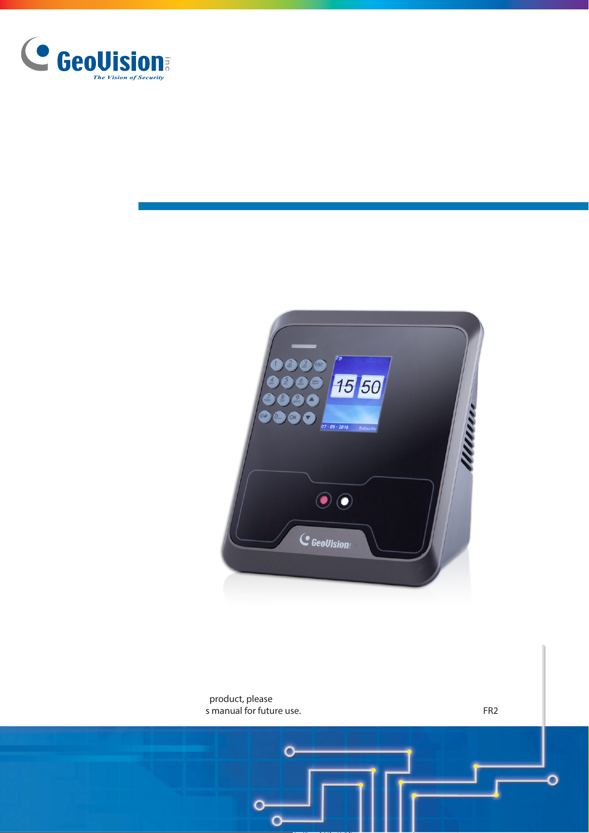
GV-FR Face Recognition Reader
GV-FR2020 User’s Manual
Before attempting to connect or operate this product, please
read these instructions carefully and save this manual for future use.
FR2020V10-A
Page 2

© 2017 GeoVision, Inc. All rights reserved.
Under the copyright laws, this manual may not be copied, in whole or in part,
without the written consent of GeoVision.
Every effort has been made to ensure that the information in this manual is
accurate. GeoVision, Inc. makes no expressed or implied warranty of any kind
and assumes no responsibility for errors or omissions. No liability is assumed
for incidental or consequential damages arising from the use of the information
or products contained herein. Features and specifications are subject to
change without notice.
GeoVision, Inc.
9F, No. 246, Sec. 1, Neihu Rd.,
Neihu District, Taipei, Taiwan
Tel: +886-2-8797-8377
Fax: +886-2-8797-8335
http://www.geovision.com.tw
Trademarks used in this manual: GeoVision, the GeoVision logo and GV
series products are trademarks of GeoVision, Inc. Windows is a
registered trademark of Microsoft Corporation.
January 2017
Page 3

Preface
Welcome to the GV-FR Face Recognition Reader User’s Manual.
This Manual applies to the following GV-FR Face Recognition Reader:
Product Version
GV-FR2020 V2.44
i
Page 4

Contents
Preface........................................................................... i
Contents....................................................................... ii
Regulatory Notices.......................................................v
Installation Considerations.........................................vi
Firmware and Software Compatibility.......................vii
Chapter 1 Introduction............................................... 8
1.1 Key Features........................................................................................................... 9
1.2 Packing List............................................................................................................10
1.3 Options...................................................................................................................11
1.4 MAC Address .........................................................................................................12
1.5 Physical Description ...............................................................................................13
1.6 Installation ..............................................................................................................15
1.7 Connecting the Reader...........................................................................................17
Chapter 2 Accessing the Reader..............................19
2.1 Using the Keypad ...................................................................................................19
2.2 Main Menu .............................................................................................................20
Chapter 3 Getting Started ..........................................21
3.1 Looking up the IP address......................................................................................21
3.2 Changing the IP address ........................................................................................22
3.3 Setup Flowchart .....................................................................................................23
Chapter 4 Access Control Conf igu rations ..............24
4.1 Connecting to GV-AS Controller.............................................................................25
4.2 Setting Up GV-ASManager.....................................................................................27
ii
Page 5

4.2.1 Adding GV-AS Controller ............................................................................ 27
4.2.2 Configuring a Door ...................................................................................... 29
Chapter 5 User Management ....................................30
5.1 Enabling the Facial Features on GV-ASManager ...................................................30
5.2 Uploading to the Face Recognition Reader ............................................................32
5.3 Using the Face Recognition Reader .......................................................................35
5.3.1 Face Recognition Mode .............................................................................. 35
5.3.2 Card Mode .................................................................................................. 40
5.4 Downloading and Uploading the Data ....................................................................40
5.4.1 Downloading the Data ................................................................................. 40
5.4.2 Uploading the Data ..................................................................................... 41
Chapter 6 Setting.......................................................42
6.1 Device Setting ........................................................................................................42
6.2 Time Setting ...........................................................................................................44
6.3 Record Rule ...........................................................................................................45
6.4 Network Setting ......................................................................................................46
6.5 Initial Setting...........................................................................................................48
Chapter 7 Inquiry.......................................................49
7.1 Registration Information ........................................................................................49
7.2 Device Information ................................................................................................50
7.3 Usage Information.................................................................................................51
Chapter 8 A Standalone Face Recognition Reader 52
8.1 Wire Definition ........................................................................................................52
8.2 Adding a User.........................................................................................................53
8.3 Enrolment modes ...................................................................................................54
8.3.1 Face Recognition Mode .............................................................................. 54
8.3.2 Card Mode .................................................................................................. 54
8.3.3 Password Mode .......................................................................................... 55
Chapter 9 Upgrading and Resetting.........................56
9.1 Upgrading System Firmware ..................................................................................56
9.2 Resetting the Reader..............................................................................................57
iii
Page 6

Specifications .............................................................58
Appendix.....................................................................60
A. GV-POE Switch Power Supply Types .......................................................................60
iv
Page 7
Regulatory Notices
FCC Notice
This equipment has been tested and found to comply with the limits for a Class A digital
device, pursuant to part 15 of the FCC Rules. These limits are designed to provide
reasonable protection against harmful interference when the equipment is operated in a
commercial environment.
Class A
This equipment generates, uses, and can radiate radio frequency energy and, if not installed
and used in accordance with the instruction manual, may cause harmful interference to radio
communications. Operation of this equipment in a residential area is likely to cause harmful
interference in which case the user will be required to correct the interference at their own
expense.
CE Notice
This is a Class A product. In a domestic environment, this product may cause radio
interference in which case the user may be required to take adequate measures.
RoHS Compliance
The Restriction of Hazardous Substances (RoHS) Directive is to forbid the use of hazardous
materials of production. To meet the RoHS Directive requirements, this product is made to
be RoHS compliant.
This product is subject to the Waste Electrical and Electronic Equipment (WEEE) Directive
and made compliant with the WEEE requirements.
WEEE Compliance
v
Page 8
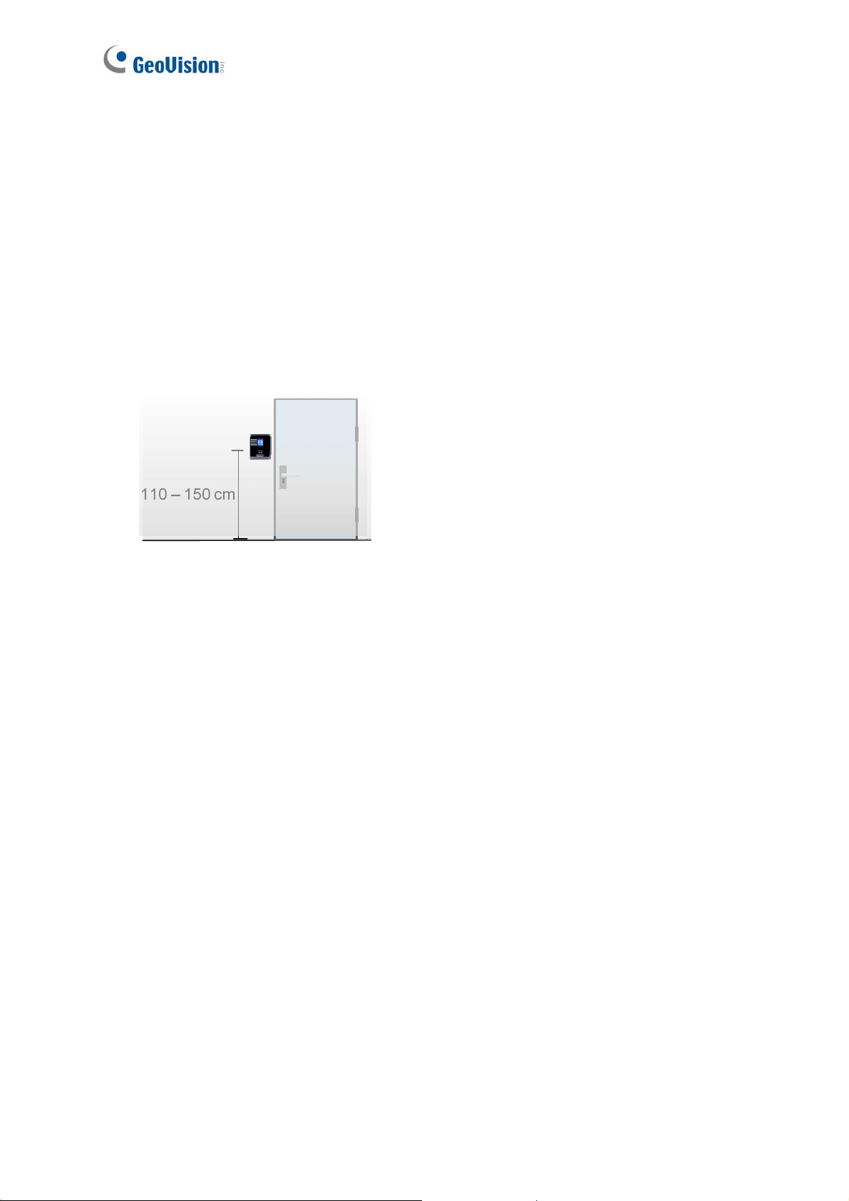
Installation Considerations
To make sure the user’s face can be recognized, follow the instructions below to set up GV-
FR2020.
Installation Height:
When placed at a building gate, GV-FR2020 should be about 1.1-1.4 meters above the
ground.
.
Face Recognition Limitations:
GV-FR2020 may not be able to recognize the user’s face wearing facial masks or
sunglasses.
Lighting Conditions:
GV-FR2020 is designed only for indoor usage. Avoid exposing to direct sunlight for user
enrollment.
vi
Page 9

Firmware and Software Compatibility
The GV-AS Controller and GV-ASManager compatible with GV-FR2020 are listed below.
GV-FR2020
GV-ASManager V4.4.2 or later
GV-AS210 / 2110 / 2120
GV-AS410 / 4110
GV-AS810 / 8110
V1.41 or later
vii
Page 10

Chapter 1 Introduction
The face recognition reader can work with GV-AS Controller and GV-ASManager to create a
complete access control system. Two types of operation modes are supported for the
integration with GeoVision controller and software: Face Recognition Mode or Card Mode.
Face Recognition Mode
The face templates are stored in the GV-FR2020. The user gains access by presenting
his/her face. The reader compares the current face collected by the sensor with all the face
data stored in the GV-FR2020. If the face is successfully authenticated, a signal is sent to
momentarily activate the door relay of the controller.
The user data are distributed through GV-ASManager to the assigned face recognition
readers installed on GV-AS Controllers for access control. Faces are enrolled in the GV-
FR2020 and GV-ASManager will synchronize the face data using TCP/IP connection.
Card Mode
You can enroll and manage users through ID cards. The user must first have an ID number
enrolled using GV-ASManager connected with a GV-FR2020. This mode requires the users
to present their assigned cards only to be granted access.
Note: GV-FR2020 can also work as a standalone device. For details, see 8. A Standalone
Face Recognition Reader.
8
Page 11

1.1 Key Features
2.4” TFT color screen, 320 x 240 pixel display
Special stereo dual sensors (Lens and IR sensor)
Up to 80 cm (31. 50 in) detection range
2000 face capacity
≤ 0.5 second verification speed
16-bit Hi-Fi voice and sound indication
12V DC, 2 A (only for standalone operation) / PoE+ (IEEE 802.3at)
Built-in 13.56 MHz Reader
Work with GV-AS21 41 / 81 series Controller and GV-ASManager
Can work as a standalone reader
1
Introduction
Two (2) access modes for the integration with GeoVision controller and software: Face
Recognition mode or Card mode
Anti-Passback (APB) support
CE, FCC compliant
9
Page 12
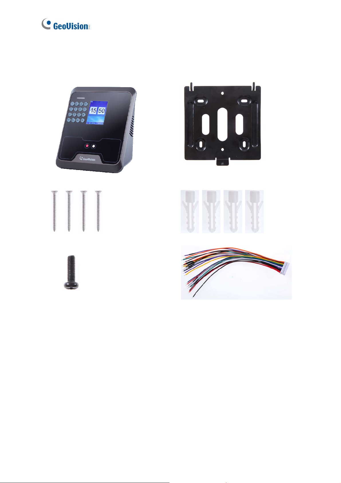
1.2 Packing List
Face Recognition Reader
Standard Screw x 4
Security Screw
Mounting Plate
Plastic Screw Anchor x 4
Data Cable
Warranty Card
10
Page 13
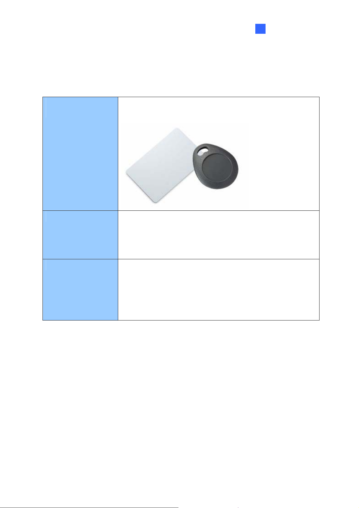
1.3 Options
You can order the following optional accessories:
1
Introduction
GV-AS ID Card &
GV-AS ID Tag
Power Adapter
GV-POE Switch
For Card Mode, the GV-AS ID Card / Tag is required. 13.56 MHz
cards and tags are available.
Contact your sales representative for the countries and areas
supported. Note this is only required for standalone mode.
The GV-POE Switch is designed to provide power along with
network connection for IP devices. The GV-POE Switch is
available in various models with different numbers and types of
ports. Note GV-FR2020 is only compatible with mid-span PoE
power supply type.
11
Page 14

1.4 MAC Address
To find the MAC address of GV-FR2020, see the Mac Address on the back of your face
recognition reader.
Figure 1-1
12
Page 15
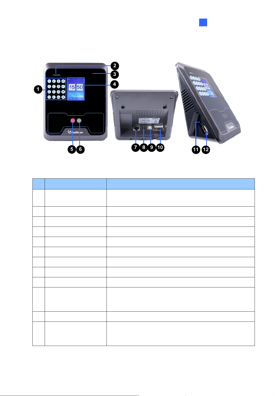
1.5 Physical Description
1
Introduction
Figure 1-2
No. Name Function
1 Keypad
2 LED Light See the LED Status section below.
3 Card Reader Reads ID cards or ID tags.
4 LCD Screen Display the menu and images.
5 Lens Capture images.
6 IR Sensor Detect IR radiation.
7 Ethernet Port Connect to network. See 1.7.1 PoE Connection.
8 Power Jack Connect to power supply.
9 USB Type-B Port Not Functional.
10 Data Port
Enter information or select functions. See 2 Accessing the
Reader.
Connect to the data cable for the connection of power and a
locking device. This function is only applicable for standalone
operation. See 8.1 Wire Definitions.
11 Reset Button Perform the system reboot. See 9.2 Resetting.
Connect to a USB 2.0 device for user data backup and
12 USB Port
firmware upgrade. See 5.4 Downloading and Uploading the
Data and 9.1 Upgrading System Firmware.
13
Page 16

LED Status
Normally, the LED on GV-FR2020 flashes green during standby mode. The LED status
under different conditions is listed below.
Condition LED
Ready Green
Access Denied Displays red LED momentarily
Access Granted Displays green LED momentarily
14
Page 17
1
Introduction
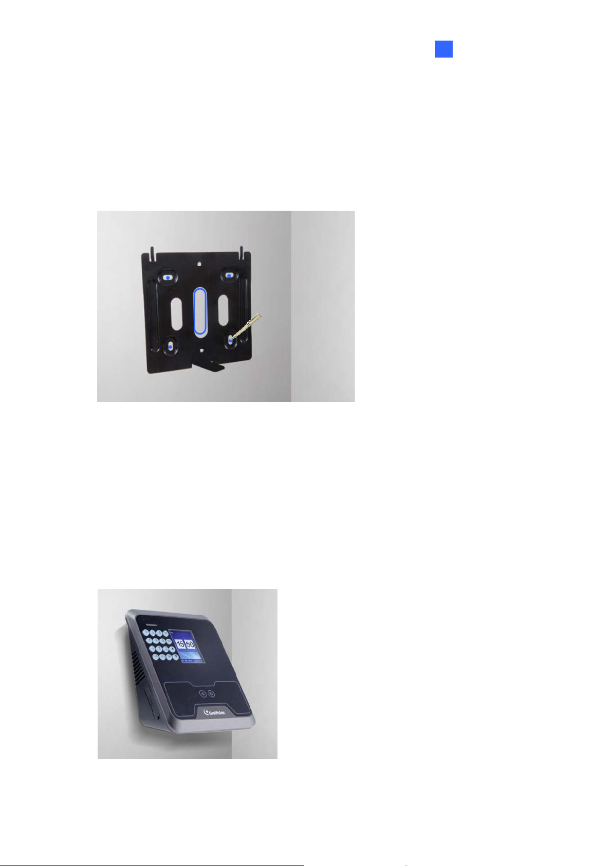
1.6 Installation
After the location of the face recognition reader is decided, follow the steps below to install
the GV-FR2020 on the wall.
1. Place the mounting plate on the wall as illustrated below.
Figure 1-3
2. Mark the location of the 4 holes and rectangle as labeled above.
3. Drill the rectangle to create a space for running the cables and wires.
4. At the 4 dots, drill a hole slightly smaller than the plastic screw anchors provided.
5. Insert the 4 plastic screw anchors in the drilled holes.
6. Place the mounting plate on the wall and secure with the 4 standard screws provided.
7. Place the face recognition reader on the mounting plate and thread the cables through
the rectangular hole.
Figure 1-4
15
Page 18

Secure the supplied security screw on the bottom with the mounting plate.
8.
Figure 1-5
16
Page 19
1
Introduction
1.7 Connecting the Reader
The face recognition reader and GV-AS Controller can be connected through the TCP/IP
interface. Follow the instructions below to connect your devices to power and network.
Note:
1. The GV-AS Controller must be under the same LAN with the GV-FR2020 you wish to
connect.
2. The GV-FR2020 can also work as a standalone device without connecting to a GV-AS
Controller. For details, see 8. A Standalone Face Recognition Reader.
You can connect your GV-FR2020 and GV-AS Controller to the hub or router with the PoE
function. The PoE function provides both power and network at the same time to the
connected devices.
Figure 1-6
Note:
1. Make sure your GV-AS Controller and GV-ASManager support the network
connection with the face recognition reader. See Firmwa r e and Softwar e Compatibilit y .
2. The PoE function is only supported by GV-AS2120. For other models of GV-AS
Controllers, you can purchase a power adapter for power connection.
17
Page 20

3. GV-FR2020 only works within mid-span power delivery. For details on which GV-POE
Switch models are supported by GV-FR2020, see Appendix A.
4. The icon
the connection between your face recognition reader and the Internet is successfully
established.
5. For standalone operation, you can prepare your own 12V power adaptor to connect
the reader to power
appearing on GV-FR2020’s main menu as shown below indicates that
18
Page 21

2
Accessing the Reader
Chapter 2 Accessing the Reader
There are different access rights granted to two types of users: Manager and User on the
GV-FR2020. While the Manager has unrestricted access to the main menu for all system
configurations, users are only granted the rights of facial or card verification.
2.1 Using the Keypad
Figure 2-1
No. Name Function
1 Alphanumeric Keys Press to input letters, numbers and special characters.
2 Special Characters Switch the input method to capital letters or special characters.
3 ESC Exit or cancel the current setting.
4 Menu Enter the main menu, or delete a previous entry.
5 Arrow keys Press to select an item.
6 OK Confirm the setting.
Note: Use the Arrow keys to choose a menu option and press OK to enter the highlighted
option. Alternatively, you can press the corresponding number key to select your desired menu
option. To cancel the option, simply press the ESC key.
19
Page 22

2.2 Main Menu
Press Menu on the keypad to enter the main menu screen, as shown below:
Figure 2-2
The Main Menu includes three submenus.
User: The user data, including the faces and cards, is stored through this submenu. It
allows the manager to add, modify or delete a user.
Setting: Contains network configurations and system-related parameters.
Inquiry: Displays the general information, including user registration, device information
and simple instructions.
20
Page 23

3
Getting Started
Chapter 3 Getting Started
You need the IP address of your GV-FR2020 so that the device can be found on the network.
This chapter shows how you can find or configure the IP address.
3.1 Looking up the IP address
By default, your face recognition reader is assigned with an unused IP address by the DHCP
server when it is connected to the network. This IP address remains unchanged unless you
unplug or disconnect your reader from the network.
Follow the steps below to check the IP address of your GV-FR2020:
Note: GV-FR2020 will get an IP address from the DHCP server only if both Eth and DHCP
are enabled on the device. For details, see 6.4 Network Setting.
1. Press the Menu button (No. 3, Figure 2-1). The Main Menu appears.
2. Select Setting and press OK, or press 2 to enter the Setting submenu.
3. In the Setting submenu, select Network and press OK, or press 4 to enter the network
setting.
4. Find the current IP address of your GV-FR2020 in the Eth field.
Figure 3-1
21
Page 24

3.2 Changing the IP address
You can modify the IP address of your GV-FR2020 to avoid an IP address conflict with other
devices on the same LAN.
Follow the steps below to assign a new IP address:
1. Press the Menu button (No. 3, Figure 2-1). The Main Menu appears.
2. Select Setting and press OK, or press 2 to enter the Setting submenu.
3. In the Setting submenu, select Network and press OK, or press 4 to enter the network
setting.
4. Select Eth to enter the Ethernet setting.
5. Select DHCP and select No to disable the DHCP function.
Figure 3-2
6. Press OK to confirm your setting.
7. Type the IP address, Netmask, the Gateway address, the DNSServer address of your
network provider.
8. Press OK to confirm your setting.
22
Page 25

3
Getting Started
3.3 Setup Flowchart
To get started quickly with GV-FR2020 settings, follow the process illustrated below.
Figure 3-3
IMPORTANT: For GV-ASManager V4.4.3.0 or later, the GV-AS Controller’s IP address will
be automatically assigned to GV-FR2020 each time you connect. You can skip 4.1
Connecting to GV-AS Controller and start from section 4.2.1.
23
Page 26

Chapter 4 Access Control Configurations
This chapter explains how to set up access control related functions by integrating your GV-
FR2020 with GV-AS Controller and GV-ASManager.
1. Connecting GV-FR2020 to GV-AS Controller
This section explains how to connect GV-FR2020 to GV-AS Controller and define the
associated door.
Figure 4-1
2. Setting up GV-ASManager
This section explains how to add GV-AS Controller to GV-ASManager and configuring a
door for GV-FR2020.
Figure 4-2
24
Page 27

4
Access Control Co nf ig urat io ns
4.1 Connecting to GV-AS Controller
To connect GV-FR2020 and GV-AS Controller through the network, you need to provide
information, such as the MAC address, IP address and port number, for your reader and GV-
AS Controller to locate and connect to each other.
IMPORTANT: For GV-ASManager V4.4.3.0 or later, the GV-AS Controller’s IP address will
be automatically assigned to GV-FR2020 each time you connect. You can skip this section
of Connecting to GV-AS Controller and start from section 4.2.
Note: The GV-AS Controller must be under the same LAN with the GV-FR2020 you wish to
connect.
1. Type the GV-AS Controller’s IP address on GV-FR2020.
a. In the Main Menu of GV-FR2020, select Setting and press OK, or press 2 to enter
the Setting submenu.
b. Select Network and press OK, or press 4 to enter the network setting.
c. Select AS-CON IP or press 4, and type the controller’s IP address.
Figure 4-3
2. Log in the Web interface of GV-AS Controller.
3. In the left menu, click Extended Reader Configuration to define the face recognition
reader connected to the controller. The Extended Reader Configuration page appears.
25
Page 28

4. T
ype the MAC address of your GV-FR2020 in the Serial Number column under GV-
Reader/CR420/GF1921/GF1922 Function section. Do not select the RS-485 box. For
details on how to look up the MAC address, see 1.3 MAC Address.
Figure 4-4
5. Use the Function drop-down list to select the door associated with your GV-FR2020.
6. Select Read UID as the Read Mode.
7. Click Submit. If the face recognition reader is detected, the Connection Status field
should turn green.
26
Page 29

4
Access Control Co nf ig urat io ns
4.2 Setting Up GV-ASManager
Integration with GV-ASManager allows you to utilize full access control functions. This
section covers basic settings on how to add GV-AS Controller and GV-FR2020 to GV-
ASManager.
For more details on GV-ASManager functions, see GV-ASManager User’s Manual.
4.2.1 Adding GV-AS Contr olle r
1. On the menu bar of GV-ASManager, click Setup and select Devices. The Controller List
dialog box appears.
Figure 4-5
2. Click the Add icon
Figure 4-6
on the top left corner. This dialog box appears.
27
Page 30

ype ID and Name of the Controller, select the Type of the Controller and click OK. This
3. T
dialog box appears.
Figure 4-7
4. In the Connection section, select Network and select TCP/IP as the communication
mode between the GV-AS Controller and GV-ASManager.
5. Type the IP address, port number, login user, password and Crypto key (3DES code)
of the GV-AS Controller. You can also click the Search button
in the same LAN.
Note: By default, GV-AS Controller has the port number 4000, username admin; password
admin; Crypto key (3DES code) 12345678.
6. To check if the above connection settings are correct, you can click OK at this step and
back to the main screen. The icon
that the connection is established.
appearing on the Device View window indicates
to search for controllers
28
Page 31

4
Access Control Co nf ig urat io ns
4.2.2 Configuring a Door
1. On the menu bar of GV-ASManager, click Setup and select Devices.
2. Double-click the GV-AS Controller and click the Door tab. This dialog box appears.
Figure 4-8
3. In the General section, select Enable to define the general settings for the door.
4. Under the GeoFace section, select Entrance or Exit and type the face recognition
reader’s IP address and port number. For details on how to check the IP address, see 3
Getting Started.
For details of the settings under the Door tab, see 4.2.2 Step 2: Configuring the Doors or
Elevator Floors in GV-ASManager User’s Manual.
29
Page 32

Chapter 5 User Management
Once you have set up access control related functions, you can begin to create and manage
users on GV-ASManager and GV-FR2020.
Note: You must first add users to GV-ASManager and then upload the user data to GVFR2020 for face enrollment.
5.1 Enabling the Facial Features on GV-ASManager
Before the user data can be submitted to a face recognition reader, you must activate the
Facial Features settings of the users. Each user must also be assigned a card number. Make
sure you have added cards, created user accounts and assigned cards to the users. See 4.3
Setting Cards and 4.6 Setting User in GV-ASManager User’s Manual.
Follow the steps below to enable the Facial Features:
1. O n the menu bar of GV-ASManager, click Personnel and select Users. The User List
window appears.
2. Click the New button
on the toolbar.
30
Page 33

User Managem ent
5
3. Click
the Features tab. This dialog box appears.
Figure 5-1
4. Click the square
5. Select User or Manager as needed.
6. Use the drop-down list to assign a card number to the user.
Figure 5-2
7. Click OK to apply the setting.
in the Facial Features section.
31
Page 34

5.2 Uploading to the Face Recognition Reader
The data can be sent directly from GV-ASManager to GV-FR2020 through TCP/IP. To
upload the user data from GV-ASManager to the face recognition reader, follow the
instruction below.
Figure 5-3
1. On the menu bar of GV-ASManager, click Setup and select Feature Access. This dialog
box appears.
Figure 5-4
2. To upload to a door or a controller, select the desired Door/Gate or controller in the top-
left panel.
3. Select Face in the Feature Type drop-down list.
4. Select the desired user data on the right side. The Add button becomes available.
32
Page 35

User Managem ent
5
5. Click
the Add button to add the selected user data to the selected Door/Gate. The
resulting window after adding may look like this:
Figure 5-5
Note: Each face recognition reader can store up to 2,000 user accounts.
6. Click the ‘x’ icon
7. Right-click the Door/Gate in the Device View on the main screen, and select Sync
GeoFace to upload all the selected user data to GV-FR2020.
to close the window of Feature Access.
Figure 5-6
33
Page 36

Click Yes to start uploading the selected user data.
8.
IMPORTANT: Each time you select Sync GeoFace, the existing user data on GV-FR2020
will be overwritten by the selected user data on GV-ASManager.
During the process of uploading the user data from GV-ASManager, you will receive the
below message on your GV-FR2020.
Figure 5-7
34
Page 37

User Managem ent
5
5.3 Using the Face Recognition Reader
After uploading the user data from GV-ASManager to GV-FR2020, you can start enrolling the
users’ face images for access control at the site of the face recognition reader. With the Card
mode, the users must present a card before access is granted.
Note:
1. A user account must be established on the connected GV-ASManager before the face
recognition enrollment can take place.
2. The enrolled face images will be saved both on the face recognition reader and the GV-
ASManager.
5.3.1 Face Recognition Mode
The Face Recognition mode must work with the GV-ASManager software and the GV-
FR2020 reader to enroll faces. To gain access, the user’s face must match the enrolled face
image.
Follow the steps below to enroll a face:
1. In the Main Menu of GV-FR2020, select User and press OK, or press 1 to enter the User
submenu.
2. Select Modify and press OK, or press 2 to access the user list.
3. Use the Arrow keys to select a user account in the list.
Figure 5-8
35
Page 38

ess OK to enter the user account details. This interface appears.
4. Pr
Figure 5-9
5. Select Modify and press OK to enter the sunshine’s test screen. GV-FR2020 will
automatically detect the current lighting conditions.
Figure 5-10
6. Press OK and the face recognition interface will be shown on the screen.
Figure 5-11
36
Page 39

User Managem ent
5
7.
Follow the voice prompts to enroll the user’s face.
8. If the face is enrolled successfully, GV-FR2020 will prompt “enrollment completed” and
return to the user account details. The user’s image will be displayed on the interface as
shown below.
Figure 5-12
9. On the menu bar of GV-ASManager, click Personnel and select Users. The User List
window appears.
Figure 5-13
37
Page 40

Double-click the user listed in the window. The User Setup dialog box appears. The
10.
image taken by GV-FR2020 is displayed as shown below.
Figure 5-14
Upon the completion of the face recognition enrollment, the user can scan his or her face to
gain access.
1. If the presented face matches any record in the face recognition reader, the confirmation
screen will appear as shown in Figure 5-13. Access signal will be passed to the controller.
The access will be granted.
38
Figure 5-15
Page 41

User Managem ent
5
O
n the Access Monitor Window of GV-ASManager, you can click the “Access Granted”
message and its associated face image will appear.
Figure 5-16
2. If the presented face does NOT match the record in the face recognition reader, the
failure screen will appear as shown in Figure 5-15. No access signal access will be sent
to the controller and the access will be denied.
Figure 5-17
39
Page 42

5.3.2 Card Mode
The Card mode allows the users to gain access with a card. Each user must have a card
number assigned by GV-ASManager.
After the GV-FR2020 has synchronized the user data with that of GV-ASManager, the user
can present the card he or she enrolled.
1. If the card is detected as an enrolled card, the access signal will be passed to the
controller and the access will be granted.
2. If the card does not match any of the enrolled cards, the access will be denied.
5.4 Downloading and Uploading the Data
5.4.1 Downloading the Data
You can back up the current user data on GV-FR2020 and save them to your USB device. In
the User submenu, select Download and press OK, or press 3 to download the user data
stored on GV-FR2020.
Figure 5-18
40
Page 43

User Managem ent
5
5.4.2 Uploading the Data
The user data can be exported to GV-FR2020 via a USB drive. In the User submenu, select
Upload and press OK, or press 4 to upload the user data.
Figure 5-19
41
Page 44

Chapter 6 Setting
The Manager can access system configuration of GV-FR2020. In the Main Menu, select
Setting and press OK, or press 2 to enter the Setting submenu.
6.1 Device Setting
Select Device and press OK, or press 1 to enter the Device Settings.
To configure a particular setting for the device, use the Arrow keys to select that item and
press OK, or input a corresponding numeric key.
Figure 6-1
Volume: Input a volume value from 0 to 10, with 5 as default. The larger the value, the
louder the volume.
Verify Mode: Select a verification mode. The default interface is the face, card or
password verification mode.
Result Time: Input the screen return time from 1 to 30 seconds after which the
verification is successful.
Protect Screen: Input an idle time, between 0 to 1440 seconds, before the screensaver
activates.
Sleep Time: Input a period from 0 to 60 minutes after which the device goes to sleep
mode.
42
Page 45

6
Setting
Lock Del
ay: Input the duration from 0 to 200 seconds for GV-FR2020 to open the
electronic locks. This function is only applicable for standalone operation.
Note: Any user can access the Setting submenu, if there are no manager accounts on the
reader. After a manager account is created, the manager can press Menu to perform face /
card / password verification before granting access to the Setting submenu.
43
Page 46

6.2 Time Setting
In the Setting menu, select Time and then press OK, or press 2 to enter the time setting. You
can press the Arrow keys to select a setting item and input numbers to define the date and
time for your GV-FR2020.
Figure 6-2
Note: The date format is shown as DD/MM/YYYY.
44
Page 47

6
Setting
6.3 Record Rule
In the Setting menu, select Rec. Rule and then press OK, or press 3 to enter the record
setting.
Figure 6-3
Reverify Time: Input a face and card re-verification time from 0 to 10 minutes.
45
Page 48

6.4 Network Setting
In the Setting menu, select Network and press OK, or press 4 to enter the Network setting.
Figure 6-4
Device No: Display the reader’s device number.
ETH: Select ETH and press OK, or press 2 to specify an IP address for the device. For
details, see Chapter 3 Getting Started.
Figure 6-5
Enable: Select Yes or No to enable or disable network connection. By default, the
network connection is enabled.
DHCP: Select Yes or No to enable or disable t
DHCP function is enabled.
46
he DHCP function. By default, the
Page 49

6
Setting
MA
IP Address: Display the IP address configured for the reader.
Netmask: Display the netmask address configured for the reader.
Gateway: Display the gateway address configured for the reader.
DNSServer: Display the DNS Server address configured for the reader.
Port No: Input the port number of the reader or keep the default value 5005.
AS-CON IP: Display the server IP address configured for the GV-AS Controller.
C: Display the MAC address of the reader.
47
Page 50

6.5 Initial Setting
You can perform a factory default reset, delete all the records and upgrade the device
firmware through the Initial Setting.
In the Setting menu, select Init and press OK, or press 5 to enter the Initial setting.
Figure 6-6
Set Default: Restores all configurations to default factory settings.
Delete all log: Removes all the log information stored on the reader.
Delete all user: Removes all the users accounts stored on the reader.
Delete all data: Removes all the stored data on the reader.
Update from USB: Upgrade the firmware of the reader via a USB device. For details,
see 9.1 Upgrading System Firmware.
Note:
1. The firmware update will not erase the user accounts stored on the reader.
2. A USB 2.0 flash drive with a maximum capacity of16 GB is required for the firmware
update.
48
Page 51

7
Inquiry
Chapter 7 Inquiry
You can check the enrolment, the device information as well as the simple usage instructions
of GV-FR2020 through the Inquiry submenu. In the Main Menu, select Inquiry and press OK,
or press 3 to enter the Inquiry submenu.
7.1 Registration Information
To see the enrolment, in the Inquiry submenu, select Reg. Info and press OK, or press 1 to
enter the registration information interface.
Figure 7-1
User quantity: Indicate the number of users enrolled on the reader.
Face quantity: Indicate the number of faces enrolled on the reader.
Card quantity: Indicate the number of cards enrolled on the reader.
Password quantity: Indicate the number of passwords enrolled on the reader.
49
Page 52

7.2 Device Information
In the Inquiry submenu, select Dev. Info and press OK, or press 2 to see the device
information.
Figure 7-2
Manufacture: Display the manufacturer of the reader.
Web Site: Display the website of the manufacturer of the reader.
Serial Num: Display the serial number of the reader.
Released: Display the released date of the reader.
Model: Display the model number of the reader.
Firmware: Display the current firmware version of the reader.
Engine: Display the engine version of the reader.
50
Page 53

7
7.3 Usage Information
In the Inquiry submenu, select Usage and press OK, or press 3 to find out the usage
information. There are some simple instructions as to how to use your reader.
Inquiry
Figure 7-3
51
Page 54

Chapter 8 A Standalone Face Recognition
Reader
GV-FR2020 can also work on its own without connecting to GV-AS Controller and GV-AS
Manager.
8.1 Wire Definition
On the back of the GV-FR2020, there is a data port (No 10, Figure 1-2). You can use the
supplied data cable to connect your face recognition reader to power and a locking device.
Note: You can purchase a12V DC power adapter for applying power adapter connection.
Figure 8-1
Wire Color Definition
Red 12V DC
Black GND
Grey Lock COM
Purple (left) Lock NC
Purple (right) Lock NO
52
Page 55

A Standalone Face Recognition Reader
8
8.2 Adding a User
After you have connected your GV-FR2020 to power and a locking device, you are ready to
enroll users. The standalone face recognition reader supports three operation modes: Face,
Card or Password.
Each user must have a user account with a unique ID number before enrolling a face, card or
password. Follow the steps below to add a user to your GV-FR2020:
1. Press the Menu button (No. 3, Figure 2-1). The Main Menu appears.
Figure 8-2
2. Select User and press OK, or press 1 to enter the User submenu.
3. Select Enrol and press OK, or press 1 to add a user. The enrollment interface appears.
Figure 8-3
53
Page 56

Input a user ID. By default, GV-FR2020 supports one-to-nine digit number.
4.
5. Press OK or the Down arrow key to save the user ID.
6. Input a user name. The text field can accept up to 14 characters.
7. Press OK to save the user name.
8. Select an enrollment mode.
Figure 8-4
8.3 Enrolment modes
The standalone GV-FR2020 supports the Face Recognition Mode, Card Mode and
Password Mode.
8.3.1 Face Recognition Mode
To enroll a face, select Face and press OK, or press 1. After the current light conditions have
been detected, follow the voice prompts to complete the enrollment.
Press ESC back to the Main Menu to test the face recognition. After the enrollment, the user
can set a card or password as another verification method by modifying the user account.
8.3.2 Card Mode
To enroll a card,
1. Select Reg Card and press OK, or press 2 for card enrollment.
2. Place the ID card on the reader.
54
Page 57

A Standalone Face Recognition Reader
8
3. Press OK to complete the enrollment.
Press ESC back to the Main Menu to test the card.
8.3.3 Password Mode
To enroll a password,
1. Select Reg Pwd and press OK, or press 3 to enroll a password.
2. Input the new password in Pwd and re-input the password in Confirm. GV-FR2020
supports 1 to 9 character-length passwords.
3. Press OK to save the password in the reader.
Press ESC back to the Main Menu and press any number key to input ID and password.
55
Page 58

Chapter 9 Upgrading and Resetting
You can upgrade or resetting your face recognition reader.
9.1 Upgrading System Firmware
The new firmware can be loaded into GV-FR2020 using a USB device.
1. Insert a USB device with the firmware update on it into the USB port (No. 12, Figure 1-2).
2. In the Main Menu of GV-FR2020, select Setting and press OK, or select 2 to enter the
Setting submenu.
3. Select Init and press OK, or press 5 to enter the Initial setting.
4. Select Update from USB to update your GV-FR2020’s firmware to the new version.
5. If the firmware update is successful, select Set Default to restore the reader to its default
settings.
Figure 9-1
Note:
1. The firmware update will not erase the user accounts, log information and other data
stored on the reader.
2. A USB 2.0 flash drive with a maximum capacity of 16 GB is required for the firmware
update.
56
Page 59

9
Upgrading and Resetting
9.2 Resetting the Reader
You can reboot your GV-FR2020 directly on the reader.
1. Keep the power connected to the reader.
2. Press and hold the reset button (No. 11, Figure 1-2) for a few seconds.
3. The reader reboots automatically.
57
Page 60

Specifications
Model GV-FR2020
Hardware
Application
LCD Display
CPU
Ambient Light
Image Sensor
Function
Detection Range
Communication Interface
Operation Mode
Firmware Upgrade
Voice Instru ction
RFID Card Supported
Number of Faces Stored
Indoor use only
2.4” TFT color screen, 320 x 240 pixel
1G MHz
0-50000 lux
Special Stereo Dual Sensors (Lens and IR sensor)
Up to 80 cm (31. 50 in)
TCP/IP (LAN)
Face Recognition, Card or Password (Password is for
standalone operation only)
USB 2.0 with a maximum capacity of 16 GB
16-bit Hi-Fi Voice and Sound Indication
13.56 MHz, 26-bit Wiegand card formats (UID only)
ISO14443A (MIFARE DESFire, MIFARE Plus and MIFARE
Classic)
2,000 (for Face Recognition mode)
Standalone Function
General
Language
Humidity
Operating Temperature
Power
PoE Power Supply Type
Digital I/O
Dimensions (H x W x D)
Weight
Certification
Yes (for Face mode, Card mode, Password mode)
English
20% ~ 80%
0 ~ 40° C (32 ~ 104° F)
12V DC, 2 A (only for standalone) / PoE+ (IEEE 802.3at)
Mid-span
1 relay output (30V DC, 3A) for standalone operation only
147 x 175 x 62 mm
(5.79 x 6.89 x 2.44 in)
0.33 kg (0.73 lb)
CE, FCC
58
Page 61

Specifications
Note:
1. The data synchronization with GV-AS Controller and GV-ASManager through LAN is only
supported with GV-AS21 / 41 / 81 series Controller firmware V1.41 or later and GV-
ASManager V.4.4.2 or later.
2. All specifications are subject to change without prior notice.
59
Page 62

Appendix
A. GV-POE Switch Power Supply Types
Model Mode
POE0800 / 1601 / 2401
End-Span
POE1611/2411
POE0400/0801
Mid-Span
POE0811/0812
End-Span
GV-POE
2, 4, 6, 8 ports
POE0810
Mid-Span
1, 3, 5, 7 ports
End-Span
2 ,4 ports
POE0410-E
Mid-Span
1, 3 ports
60
 Loading...