

Page 1

GV-CMS Series
User’s Manual V8.3
Page 2

© 2009 GeoVision, Inc. All rights reserved.
Under the copyright laws, this manual may not be copied, in whole or in part,
without the written consent of GeoVision.
Every effort has been made to ensure that the information in this manual is
accurate. GeoVision is not responsible for printing or clerical errors.
GeoVision, Inc.
9F, No. 246, Sec. 1, Neihu Rd.,
Neihu District, Taipei, Taiwan
Tel: +886-2-8797-8377
Fax: +886-2-8797-8335
http://www.geovision.com.tw
Trademarks used in this manual: GeoVision, the GeoVision logo and GV
series products are trademarks of GeoVision, Inc. Windows and Windows
XP are registered trademarks of Microsoft Corporation.
January 2009
Page 3

User’s Manual for
Central Monitoring Station
Welcome to the User’s Manual for Central Monitoring Station (CMS).
This Manual provides these solutions for your CMS installation and
management:
z Center V2
z Dispatch Server
z Vital Sign Monitor (VSM)
z Control Center
z GV-GIS
A simple comparison of these solutions:
Application Feature
Center V2 Live videos and text alerts;
Display up to 42 screen divisions;
Serve up to 500 subscribers and 800 channels
(professional edition);
Remote playback.
Dispatch Server Solve the problem of network overload on Center V2
Server by distributing subscribers’ monitoring
requests to other Center V2s;
Remote playback.
Vital Sign
Monitor (VSM)
Control Center Access subscribers’ systems and desktops remotely;
Live text alerts and playback of videos, ideal for low
bandwidth network;
Notify video log storage and hard disk space;
Serve up to 1,000 subscribers.
Display up to 96 screen divisions x 6 monitors;
Remote playback;
I/O Central Panel.
Page 4

Contents
Chapter 1 Center V2...............................................................................1
1.1 System Requirements..................................................................2
1.2 Installing Center V2......................................................................3
1.3 The Center V2 Window................................................................4
1.4 Creating a Subscriber Account.....................................................8
Creating a Subscriber ............................................................9
Subscriber Settings..............................................................11
Attachment Mode Settings...................................................13
Changing the Color of Channel Heading .............................15
1.5 Connecting to Center V2............................................................16
Setting Normal Mode ...........................................................18
Setting Panic Button.............................................................27
Detecting Input Status..........................................................28
1.6 Instant Recording and Playback.................................................29
Enabling Live View...............................................................29
Recording and Playing Back................................................30
Playing Back with EZ Player................................................30
1.7 Monitoring and Managing Subscribers.......................................32
Showing I/O Status...............................................................32
Controlling I/O Devices ........................................................33
Camera/Audio Control Window............................................34
Simple Audio and Microphone Panels.................................36
Camera Monitor ...................................................................37
Viewing Subscriber Information ...........................................39
Subscription Control.............................................................39
1.8 Subscriber Schedule..................................................................40
Setting a Schedule...............................................................40
Scheduling Alert Notification ................................................42
1.9 Alarm Report..............................................................................43
Creating an Alarm Report.....................................................43
Editing Alarm Report Categories..........................................44
ii
Page 5

Printing Alarm Reports .........................................................45
1.10 Colorful Flags.............................................................................46
Marking the Events with Colorful Flags................................46
Editing Colorful Flags...........................................................47
1.11 Event Log Browser.....................................................................48
Opening the Event Log ........................................................49
Filtering the Event Log.........................................................50
Backing up the Event Log....................................................51
Setting the Event Log...........................................................53
Setting the Printout...............................................................54
1.12 System Configuration.................................................................55
General Settings ..................................................................55
Layout Settings ....................................................................57
Network Settings..................................................................58
Recording Settings...............................................................59
Dispatch Server Settings......................................................60
1.13 Notification Settings....................................................................61
1.14 Output Alerts...............................................................................63
Forcing Outputs of Center V2 ..............................................63
Forcing Outputs of a Subscriber ..........................................63
1.15 SMS Alerts..................................................................................64
Setting SMS Server..............................................................64
Connecting to SMS Server ..................................................66
Sending SMS.......................................................................66
1.16 E-Mail Alerts...............................................................................67
Setting Mailbox.....................................................................67
Sending E-Mail.....................................................................68
1.17 E-Map Alerts...............................................................................69
1.18 Backup Servers..........................................................................70
1.19 Assigning a Subscriber to Another Center V2............................72
Chapter 2 Dispatch Server ..................................................................73
2.1 System Requirements................................................................74
2.2 Installing Dispatch Server...........................................................75
iii
Page 6

2.3 The Dispatch Sever Window......................................................76
2.4 Creating a Subscriber Account...................................................77
2.5 Starting Dispatch Server.............................................................79
2.6 Connecting Center V2 to Dispatch Server.................................79
2.7 Connecting GV-System to Dispatch Server ...............................80
2.8 Event Query ...............................................................................81
2.9 Event List....................................................................................82
Colorful Flags.......................................................................84
2.10 Subscription Schedule................................................................85
2.11 Colorful Mode of Live Video.......................................................85
2.12 Log Browser...............................................................................86
Dispatch Log Browser..........................................................86
Event Log Browser...............................................................87
2.13 System Configuration.................................................................88
2.14 SMS Alerts..................................................................................91
2.15 E-Mail Alerts...............................................................................91
2.16 Backup Servers..........................................................................92
Chapter 3 Vital Sign Monitor...............................................................95
3.1 System Requirements................................................................96
3.2 Installing VSM ............................................................................97
3.3 The VSM Window.......................................................................98
3.4 Creating a Subscriber Account.................................................101
3.5 Starting VSM............................................................................102
3.6 Connecting to VSM..................................................................102
Advanced Settings for Subscription...................................103
Detecting Input Status........................................................109
3.7 Monitoring Subscribers.............................................................110
Viewing Subscriber Status................................................. 110
Viewing Storage Information.............................................. 111
Subscription Control........................................................... 112
3.8 Subscriber Schedule................................................................ 113
3.9 Alarm Report............................................................................ 113
3.10 Remote Playback..................................................................... 114
iv
Page 7

3.11 Event Log Browser...................................................................115
3.12 System Configuration...............................................................116
System Settings................................................................. 116
Password Settings .............................................................118
Event Log Settings.............................................................118
Notification Settings ...........................................................118
3.13 Output Alerts.............................................................................119
Forcing Outputs of VSM..................................................... 119
Forcing Outputs of a Subscriber ........................................119
3.14 SMS Alerts................................................................................120
Setting SMS Server............................................................120
Sending SMS.....................................................................120
3.15 E-Mail Alerts.............................................................................123
Setting Mailbox...................................................................123
Sending E-Mail...................................................................123
3.16 Backup Servers........................................................................124
Chapter 4 Control Center ..................................................................125
4.1 System Requirements..............................................................126
4.2 Installing Control Center...........................................................127
4.3 The Control Center Toolbar......................................................128
The Edit Toolbar.................................................................128
The Service Toolbar...........................................................130
4.4 Creating Hosts and Groups......................................................131
Creating a Host..................................................................132
Creating a Group................................................................133
4.5 Connecting to the Control Center.............................................134
The Control Center Server Window...................................134
Configuring the CCS Server...............................................136
4.6 Live View..................................................................................138
4.7 Remote DVR............................................................................140
4.8 Remote Desktop.......................................................................142
Running Remote Desktop..................................................142
v
Page 8

File Transfer.......................................................................142
4.9 Remote ViewLog......................................................................144
Running Remote ViewLog .................................................144
4.10 Matrix View...............................................................................145
Running Matrix View..........................................................145
Configuring Matrix View.....................................................148
POS Live View...................................................................150
Instant Playback.................................................................151
QView for Channel Display on Another Monitor.................152
4.11 IP Matrix...................................................................................153
Running IP Matrix...............................................................154
The Controls on the Window..............................................157
4.12 VMD Monitoring........................................................................159
Running VMD.....................................................................159
The Controls on the Window..............................................160
4.13 Instant Playback.......................................................................162
4.14 PIP and PAP View....................................................................164
4.15 Panorama View........................................................................166
Creating a Panorama View................................................166
Accessing a Panorama View .............................................166
Panorama View Controls ...................................................166
4.16 I/O Central Panel......................................................................167
Running the I/O Central Panel...........................................167
The I/O Central Panel ........................................................168
Creating a Group for Cascade Triggers.............................169
Configuring the I/O Central Panel......................................174
Setting Up Mode Schedule ................................................175
Quick Link ..........................................................................177
Forcing Output ...................................................................178
Editing Background Image.................................................179
Managing a Group of I/O Devices......................................180
Controlling I/O Devices ......................................................181
Popping Up Live Video after Input Trigger.........................182
4.17 Remote E-Map.........................................................................184
vi
Page 9

4.18 Colorful Mode of Live Video.....................................................184
4.19 Changing Interface Style..........................................................185
The Standard Window........................................................185
4.20 System Configuration...............................................................186
General Settings ................................................................186
Chapter 5 GV-GIS...............................................................................197
5.1 Features...................................................................................198
5.2 System Requirements..............................................................199
5.3 Overview of GV-GIS.................................................................201
Main Screen.......................................................................201
Toolbar ...............................................................................202
Event List ...........................................................................204
5.4 Getting Started.........................................................................205
Installing the GV-GIS..........................................................205
Creating Host Accounts......................................................207
Connecting Hosts to the GV-GIS.......................................210
5.5 Tracking Operations for Mobile Hosts......................................212
Starting the Tracking Services............................................212
Tracking Features..............................................................212
Viewing Live Video.............................................................215
Playing Back GPS Tracks..................................................217
Tracking Multiple Hosts......................................................219
Detecting Detours ..............................................................221
Searching for Places and Devices.....................................224
Detecting Idle Speed..........................................................228
5.6 Monitoring Operations for Fixed Hosts.....................................230
Starting the Monitoring Services........................................230
Monitoring Features...........................................................231
Detecting Motion and Input-Triggered Events....................233
Retrieving Recorded Video................................................235
5.7 Advanced Operations...............................................................238
Creating an E-Map.............................................................238
vii
Page 10

Configuring E-Map Icon settings........................................239
Adding a Place...................................................................240
Saving a View ....................................................................241
Getting Driving Directions ..................................................242
5.8 System Configurations.............................................................243
Layout Settings ..................................................................243
Network Settings................................................................244
Event Log Settings.............................................................245
Remote ViewLog Settings..................................................246
Colorful Mode.....................................................................246
5.9 Event Log Browser...................................................................247
Opening the Event Log ......................................................249
Filtering the Event Log.......................................................250
Backing Up the Event Log..................................................251
Printing the Event Log........................................................253
5.10 Shortcut Keys...........................................................................254
Appendix…. ............................................................................................255
A. Dongle Description...................................................................256
Dongle options for Center V2.............................................256
Dongle options for Dispatch Server ...................................256
Dongle options for VSM.....................................................257
Dongle options for Control Center .....................................257
B. Upgrading the Black Dongle.....................................................258
C. Fast Backup and Restore.........................................................260
Installing the FBR Program................................................260
Selecting a Skin .................................................................261
Backing Up and Restoring Settings ...................................261
D. PTZ Control Using GV-Joystick................................................264
E. Matrix Control Using GV-Keyboard..........................................265
F. Supported IP Devices...............................................................267
Center V2...........................................................................267
Control Center....................................................................267
G. Specifications...........................................................................272
viii
Page 11

Center V2...........................................................................272
Dispatch Server..................................................................273
Comparison of VSM and Center V2 Pro............................274
Control Center....................................................................275
ix
Page 12

x
Page 13

Chapter 1 Center V2
With Center V2, central monitoring station (CMS) can be deployed
immediately because it brings multiple GV-Systems together into an
integrated interface, allowing the operator to manage several systems from
one point of control. The basic feature of Center V2 is to view live video,
and receive video evidence (in an attachment format) when any alerts are
sent to Center V2. This helps the remote-end operator easily determine the
nature of the alarm.
Page 14

1.1 System Requirements
There are two versions of Center V2. The standard version, coming with
system software, can serve up to 5 subscribers and 80 channels at a time.
The professional version can serve up to 500 subscribers and 800
channels.
Before installation, make sure your computer meets the following minimum
requirements.
Standard Version
OS Windows 2000 / XP / Server 2003 / Vista
CPU Pentium 4, 2.6 GHz, 800MHz FSB
Memory 2 x 256 MB Dual Channels
Hard Disk 60 GB
VGA NVIDIA GeForce 4 MX440 64 MB
Network TCP/IP
Professional Version
OS Windows 2000 / XP / Server 2003 / Vista
CPU Core 2 Duo E6600, 2.4 GHz, 1066 MHz FSB
Memory 2 x 1 GB Dual Channels
Hard Disk 250 GB
VGA NVIDIA 8600GT / ATI X1650
Network TCP/IP
Note: Currently the 64-bit Windows operating system is not supported.
2
Page 15

Center V2
1
1.2 Installing Center V2
1. Insert the CMS Sof twar e CD to your computer. It will automatically run
and a window appears.
2. Select Install V8.3.0.0 Central Monitoring System.
3. Click Center V2 System, and follow the on-screen instructions.
Note: The Center V2 Pro application is provided with a USB dongle.
Make sure the dongle is tightly attached to your computer.
3
Page 16
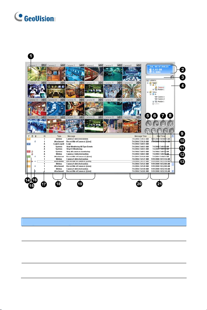
1.3 The Center V2 Window
Figure 1-1
The controls on the Center V2 window:
No. Name Description
Monitoring
1
Window
2 Status Panel
Find A
3
Subscriber
4
Displays live video.
Indicates the date, time, remaining disk space, and
the total number of online channels versus available
channels.
Type the desired ID in the Current Subscriber field
and click this button to search.
Page 17

Center V2
1
Displays subscribers’ ID names and online status.
Blue Icon: Indicates the subscriber is online.
4 Subscriber List
Gray Icon: Indicates the subscriber is off-line.
Alarm Icon: Indicates either motion has been
detected or the I/O has been triggered at the
subscriber’s site.
Accesses Event Log, Event List, audio and
5 Tools
microphone control, SMS Server configuration, and
short message notification.
Host
6
Information
Displays the connection status of subscribers.
7 Accounts Adds, deletes or modifies subscriber accounts.
Brings up these options: System Configure, Event
Log Settings, Notification, Password Setup, E-mail
Setup, Customize Alarm Report, SMS Setup, I/O
Device, Automatic Failover Support and Version
8
Preference
Settings
Information.
9 Previous Page Displays the previous page of camera views.
10 Next Page Displays the next page of camera views.
Refresh
11
Channel
Refreshes the connection status.
In the 1024 x 768 resolution, select 6, 15, or 24
screen divisions for a single monitor; 9, 25, or 36
screen divisions for dual monitors.
In the 1280 x 1024 resolution, select 6, 12, or 24
screen divisions for a single monitor; 9, 20, or 42
12 Split Mode
screen divisions for dual monitors.
In the 1600 x 1200 resolution, select 6, 12, or 24
screen divisions for a single monitor; 9, 16, or 36
screen divisions for dual monitors.
In the 1680 x 1050, 1920 x 1200 and 1440 x 900
resolutions, select 6, 15, or 28 screen divisions for a
single monitor; 9, 20, or 42 screen divisions for dual
5
Page 18

monitors.
n the 1920 x 1200 resolution, select 6, 15, or 28
screen divisions for a single monitor; 9, 20, or 42
screen divisions for dual monitors.
In the 1920 x 1080 resolution, select 6, 15, or 28
screen divisions for a single monitor; 6, 20, or 35
screen divisions for dual monitors.
In the 1280 x 800 resolution, select 6, 12, 24 screen
divisions for a single monitor; 9, 16, 30 screen
divisions for dual monitors.
For resolution, see Layout Settings later in this
chapter.
13 Exit Closes or minimizes the Center V2 window.
14 Flag Flags an event for later reference.
15 Clipboard Displays the Alarm Report dialog box.
16 Clip
Indicates an event coming with an attachment.
Double-click the event to open the attached video file.
17 ID Indicates a subscriber’s ID.
Indicates the event type: Alarm, Attachment,
18 Event Type
Connection, Login/Logout, Motion, System, and
Trigger.
19 Message Indicates associated information for each event type.
20 Message Time Indicates when Center V2 receives an event.
21 Start Time
Indicates when an event happens at the subscriber’s
site.
6
Page 19

Center V2
1
A list of Types and Messages will be displayed on Center V2:
Type Message
Motion Camera xx detected motion.
Trigger Module xx triggered.
Camera xx video lost; Module xx I/O lost; Network abnormal;
Fail to login to dispatch server; Dispatch server is shutdown;
Connection
Video signal of xx has resumed; Module xx has returned to
normal; Failed to login SMS server; Failed to send short
message; SMS server is shutdown.
Disk Full; Restarted Failed; Multicam Closed; There isn’t
enough space for recording; Multicam Surveillance System
Alarm
has been closed; An unexpected error occurred in Multicam
Surveillance System. (Error Code: 1 or 2); There is an
intruder; Object Missing; Unattended Object; Alert Message
of POS; Scene Change.
Start/end service; IP change; Record failed; Status change of
monitoring camera. On: xx Off: xx / (By Schedule); Stop/start
all cameras monitoring; Start/stop I/O Monitoring. / (By
Schedule); Schedule start; Schedule stop. All monitoring
System
devise are stop too. Start monitoring all type events; Stop
monitoring all type events; Subscriber session is not
established. Wait-time expired; Unexpected logout before
subscriber session is completed; Can’t find USB Protection
Key.
Attachment Record file of Camera xx.
Note: Error Code 1 indicates a codec error; Error Code 2 indicates that
users can’t write or record any data due to HD failure or user privilege.
7
Page 20
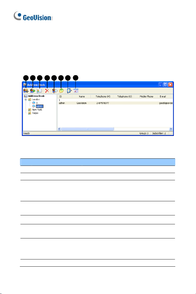
1.4 Creating a Subscriber Account
Create at least one subscriber before starting Center V2 services. On the
Center V2 window, click the Accounts button (No. 7, Figure 1-1). The
Address Book window appears.
1 2 3 4 5 6 7
The buttons on the Address Book:
No. Name Description
1 Add A Group Adds a group.
2 Add A Subscriber Adds a subscriber.
View / Edit Subscriber
3
Address Book
Delete
4
A Group / Subscriber
5 Find A Subscriber Searches a subscriber account.
Import / Export
6
Address Book
7 Subscriber Settings
8 Subscriber Schedule Sets up subscription schedules.
8
Figure 1-2
Highlight one subscriber and click this button
to open Subscriber Address Book for viewing
and editing.
Highlight a group or a subscriber and click
this button to delete it.
Imports or exports the address book data.
Highlight one subscriber and click this button
to configure the settings of video and alert
formats.
8
Page 21
Center V2
1
Creating a Subscriber
1. Click the Add A Group button (No. 1, Figure 1-2) to create a group.
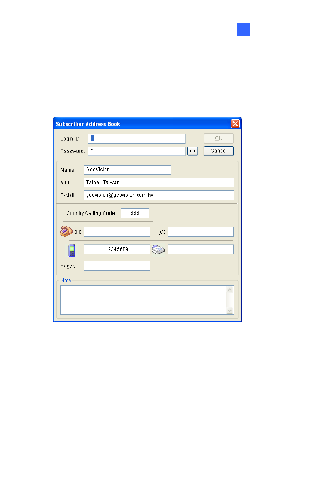
2. Click the Add A Subscriber button (No. 2, Figure 1-2). The
Subscriber Address Book dialog box appears.
Figure 1-3
3. Enter a Login ID and Password (required). Those will be the ID and
Password for the subscriber to log in to the Center V2.
9
Page 22
4. Enter the subscriber’s contact information in the rest of fields
(optional).
¾ If you wish to send e-mail alerts to this subscriber, type its
e-mail address. For e-mail settings, see E-Mail Alerts later in
this chapter.
¾ If you wish to send SMS alerts to this subscriber, type its
country code and mobile number. For SMS Server settings, see
SMS Alerts later in this chapter.
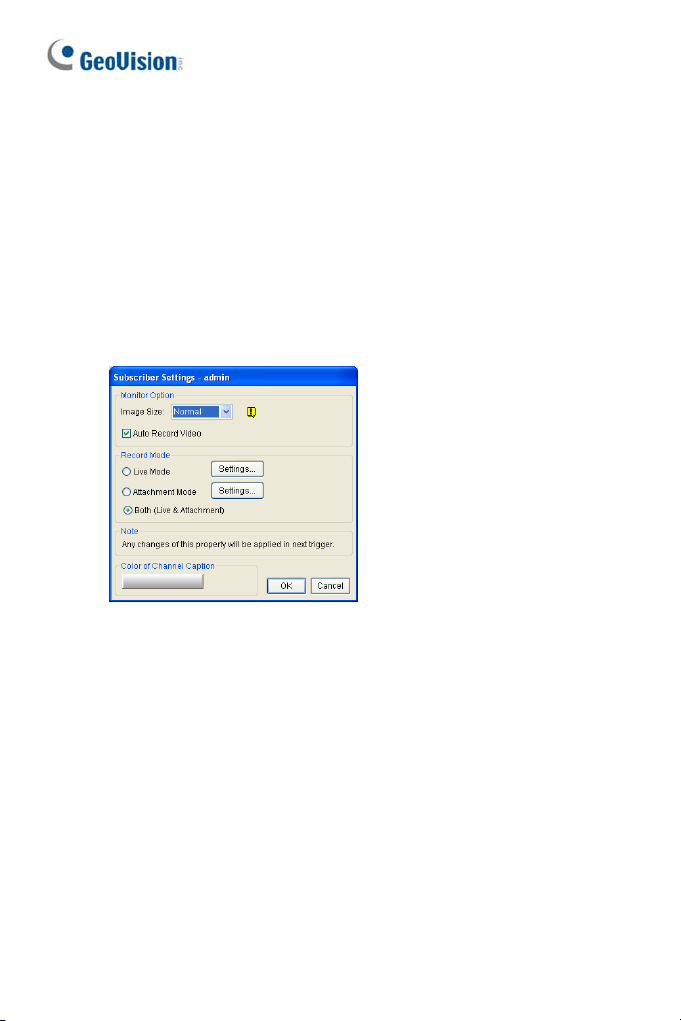
5. Click OK to save the above settings. This dialog box appears.
Figure 1-4
6. The options in the dialog box are discussed below. You may accept
the default settings here, and edit them later by clicking the
Subscriber Settings button (No. 6, Figure 1-2) on the toolbar. When
you click OK, the subscriber account then is created.
10
Page 23

Center V2
1
Subscriber Settings
[Monitor Option]
Image Size: Sets the video size from the subscriber. The following
chart shows how the image size set at the subscriber corresponds to
different settings at Center V2. For example, if the video stream from
a subscriber is 720 x 576 and Center V2 operator selects Middle, the
size of displayed image on Center V2 is 720 x 288.
Subscriber
Center V2
Actual Size 320 x 240 360 x 240 360 x 288 640 x 240 640 x 480 720 x 240 720 x 480 720 x 576 1280 x 960
Center V2 supports mega pixel resolution. If the subscriber sets the
resolution to mega pixel and the Center V2 operator wishes to view the
videos of the same size, the Center V2 operator can select Actual Size.
Note this setting will require a lot of bandwidth. It is recommended to select
the option in LAN environment.
Note: For the client GV-System, it is required to activate the Enable
hardware-compressed data FIFO function so that Center V2 can
receive megapixel streams. For this function, see Advanced Settings,
Chapter 2 in User’s Manual on the Surveillance System Software CD.
Auto Record Video: Center V2 automatically records events based
320 x 240 360 x 240 360 x 288 640 x 240 640 x 480 720 x 240 720 x 480 720 x 576 1280 x 960
Normal 320 x 240 360 x 240 360 x 288 320 x 240 320 x 240 360 x 240 360 x 240 360 x 288 320 x 240
Middle 320 x 240 360 x 240 360 x 288 640 x 240 640 x 240 720 x 240 720 x 240 720 x 288 640 x 240
Large 320 x 240 360 x 240 360 x 288 640 x 240 640 x 480 720 x 240 720 x 480 720 x 576 640 x 480
on the following Record Mode.
11
Page 24

[Record Mode]
Live Mode: Streams live video to Center V2. Make sure you have
enough bandwidth to receive video in live. To set the maximum
duration of a video file recorded on Center V2, click the Settings
button.
Attachment Mode: A defined time of event will be recorded before
sending to Center V2. The attachment will be sent out immediately
once your subscriber is connected to Center V2. The Attachment
Mode also provides several options associated with the attachment.
Click the Settings button to bring up the Record Settings –
Attachment Mode dialog box. See Attachment Mode Settings below
for further setup.
Both (Live & Attachment): Sends both live video and attachment
files.
[Color of Channel Caption]
Changes the color of channel headings. For further setup, see Changing
the Color of Channel Heading later in this chapter.
12
Page 25
Center V2
1
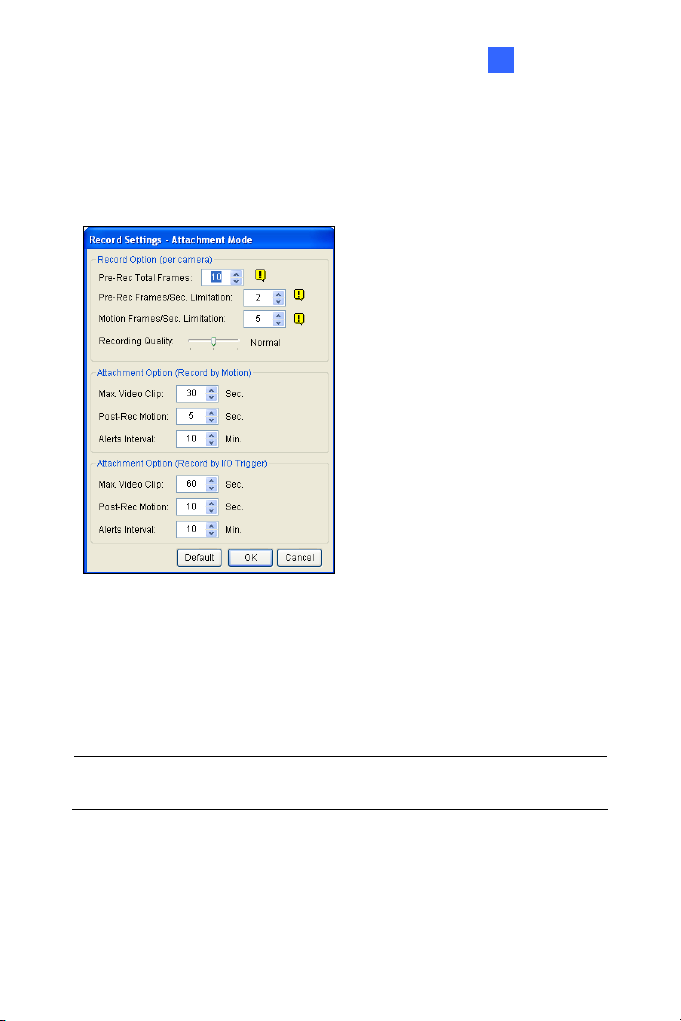
Attachment Mode Settings
In the Subscriber Settings dialog box (see Figure 1-4), select Attachment
Mode, and click the Settings button beside. This dialog box appears.
[Record Options (per camera)]
Pre-Rec Total Frames: Determines the total pre-recorded frames in
Pre-Rec Frames/sec Limitation: Determines the frame rate in the
Note: Dividing the Pre-Rec Total Frames by Pre-Rec Frames/Sec
Limitation, you will get the total time of the video attachment.
Figure 1-5
a video attachment.
pre-recorded period.
13
Page 26

Motion Frames/sec Limitation: Determines the frame rate of the
video to be sent as an attachment.
Recording Quality: Use the slider bar to adjust the video quality in
3 levels.
[Attachment option (Record by Motion)] Defines the duration of the
video attachment delivered upon motion.
Max video Clip: Determines the duration of the video attachment.
Pos-Rec Motion: Determines how many more seconds of video to
be sent when motion stops.
Alerts interval: Determines the interval between sent motion
events.
[Attachment option (Record by I/O trigger)] Defines the duration of the
video attachment delivered upon I/O trigger.
14
Page 27
Center V2
1
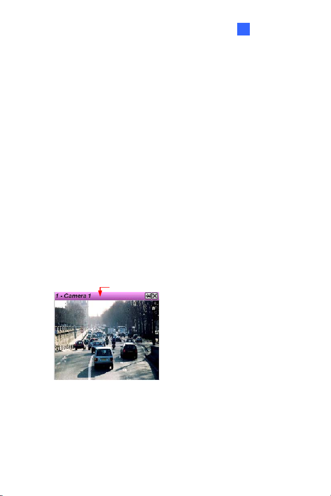
Changing the Color of Channel Heading
For easy identification, the channel headings can be as colorful as you
wish. In addition to the change of color and font of the channel headings,
its background color can be customized as well.
1. On Center V2 window, click the Accounts button (No.7, Figure 1-1),
highlight a subscriber, and click the Subscriber Setting button on the
toolbar. The Subscriber Settings dialog box (see Figure 1-4) appears.
2. Click the Color of Channel Caption button. The color dialog box
appears.
3. Select a color you wish to use, and click OK. The Color of Channel
Caption button now displays the color you selected.
4. On the Center V2 window, click the Preference Setting button (No. 8,
Figure 1-1) and select System Configure. The Preference dialog box
(see Figure 1-38) appears.
5. Click the General tab, and check the Use the subscriber setting
color as background option. Now the background color of the
channel heading will be in the color you selected.
Channel Heading
Figure 1-6
15
Page 28
1.5 Connecting to Center V2
A single DVR can connect up to two Center V2 centers simultaneously for
central monitoring. To configure GV-System in order to access Center V2
remotely through a network connection, follow these steps:
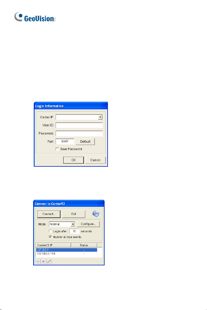
1. In the Main System, click the Network button, and select Connect to
Center V2. This dialog box appears.
Figure 1-7
2. Type the IP address, ID and password of a Center V2. Modify the
default port if necessary. Click OK. This dialog box appears.
Figure 1-8
16
Page 29

Center V2
1
3. If you want to establish the connection to the second Center V2, click
the button.
4. If you want to modify the login information of the established Center
V2, select the desired Center V2 in the dialog box, and click the
button.
5. If you want to delete the established Center V2, select the desired
Center V2 in the dialog box, and click the button.
6. When you finish the settings, click the Connect button to start. When
the connection is established, Center V2 will start receiving video or
attachments from the subscriber.
17
Page 30
Setting Normal Mode
To further define the communication conditions between the subscriber and
Center V2, select Normal Mode in the Connect to Center V2 dialog box
(Figure 1-8), and then click the Configure button for setup. A menu
includes two options of General Settings and Advance Settings. The
Advance Settings dialog box includes these tabs: (1) Camera, (2) Other
and (3) I/O Device.
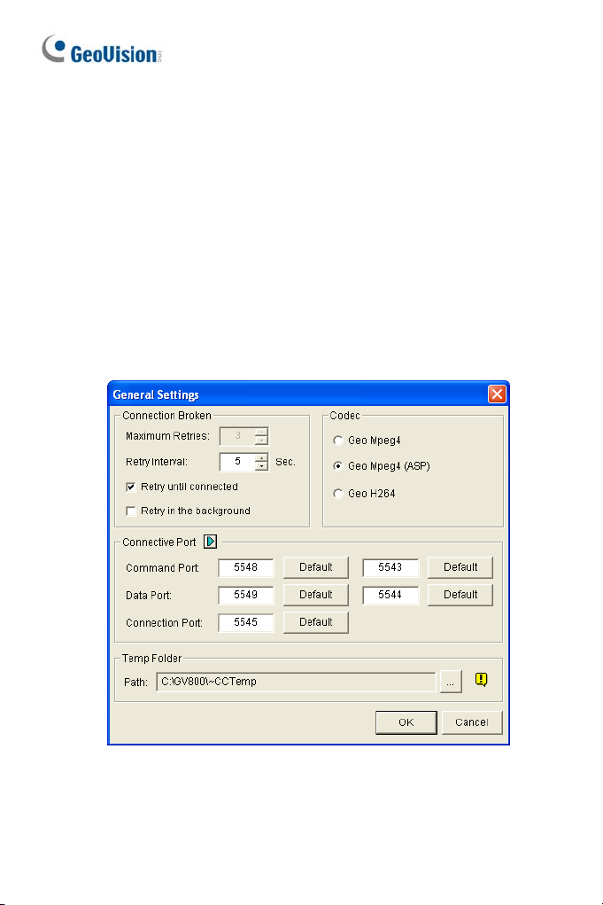
General Settings
The settings define the retry modes and communication ports between
GV-System and Center V2.
18
Figure 1-9
Page 31

Center V2
1
[Connection Broken]
Maximum Retries: Sets the number of retries if connection is not
immediately available.
Retry Interval: Sets the interval between retries.
Retry until connected: Keeps GV-System on trying until connected
to Center V2.
Retry in the background: Hides the retries in the background.
[Codec] Selects Geo Mpeg 4 (default), Geo Mpeg 4 (ASP) or Geo H264
as the compression method for video sent to Center V2.
[Connective Port] Displays ports used for communication. It is
recommended to keep the default settings, unless otherwise necessary.
Note that there are two sets of Command Ports and Data Ports for those
who wish to establish the connection to two Center V2 centers.
To automatically configure these ports on your router by UPnP technology,
click the Arrow button. For details, see UPnP Settings, Chapter 8, User’s
Manual on the Surveillance System Software CD.
[Temp Folder] Attachments are temporarily stored in this folder while
waiting to be sent to Center V2. In case the connection is broken,
attachments meant to be sent to Center V2 could be found here. Once the
connection is back to normal, events saved in the Temp Folder will be sent
out immediately.
19
Page 32

Advanced Settings
[Camera]
The settings define which camera condition to notify Center V2. To
configure the event type, first disable the Monitoring all type events
option in Figure 1-8.
Figure 1-10
The Arrow buttons: Click the left or right arrow button to select the
camera to be configured. Or you can click the Finger button to apply
the settings to all cameras.
Send to Center V2 when Motion is Detected: Sends video to
Center V2 when motion is detected. Click the Set Camera(s) button
to assign cameras for the application.
Event Type: If the subscriber wants Center V2 always to get notified
of motion detection, select Emergency. If the subscriber wants
Center V2 to get notified of motion detection only when an assigned
input is triggered, select Normal.
20
Page 33

Center V2
1
Allow Center V2 to View Live Camera: Gives Center V2 the
privilege to view your cameras at any time. Click the Set Camera(s)
button to assign cameras for the application.
Allow Center V2 to Control PTZ Camera: Gives Center V2 the
privilege to control your PTZ cameras. Remember to properly set up
camera mapping first. See Mapping PTZ Cameras, Chapter 1, User ’s
Manual on the Surveillance System Software CD.
Notify Center V2 when the following events come up: Notifies
Center V2 when any of these alert events occur: Intruder, Missing
Object, Unattended Object and Scene Change.
Event Type: If the subscriber wants Center V2 always to get notified
of these alert events, select Emergency. If the subscriber wants
Center V2 to get notified of these alert events only when an assigned
input is triggered, select Normal.
Note: To set an input trigger for the notification of Normal events, see
Security Service, [I/O Device] later in this chapter.
21
Page 34

[Other]
Define other communication conditions between GV-System and Center
V2.
Figure 1-11
[Audio] Applies any of these options here may generate privacy issues.
Think before you make any selection.
Allow Audio-Out to CenterV2: Allows Center V2 to listen to the
audio from GV-System.
Accept Audio-In from CenterV2: Allows Center V2 to use the
talkback feature when emergency occurs.
22
Page 35

Center V2
1
[Other]
Allow Center V2 to Get System Information: Allows Center V2 to
get system information on your GV-System.
Send Alert Message of POS’s Loss Prevention to Center V2:
Notifies Center V2 about the events of POS Loss Prevention.
Time synchronization with Center V2: Enables the time
increment/decrement of minutes and seconds at the subscriber site to
match the time at the Center V2.
Notify Center V2 when the storage space was full: Notifies the
Center V2 when the subscriber’s storage space is insufficient.
23
Page 36

[I/O Device]
The settings define which I/O condition to notify Center V2. To configure
these settings, first disable the Monitoring all type events option in Figure
1-8.
Figure 1-12
[I/O Device] Notifies the Center V2 of when I/O devices are triggered.
Use the Arrow buttons to configure each I/O device, or click the Finger
button to apply to all I/O devices.
Allow Center V2 to Enable / Disable I/O: Allows Center V2
manually arm/disarm any I/O devices at the subscriber’s site without
interrupting the monitoring.
For example, when an alarm is triggered at the subscriber site, the
Center V2 can turn it off remotely before arriving at the site.
Meanwhile, GV-System still remains on monitoring.
24
Page 37

Center V2
1
Send to Center V2 when I/O is Triggered: Notifies Center V2
when any selected input is triggered.
With Camera(s): Sends the camera video to Center V2 when the
selected input is triggered. Click the Set Camera(s) button to assign
cameras for the application.
Event Type: If the subscriber wants Center V2 always to get notified
of the input trigger, select Emergency. If the subscriber wants Center
V2 to get notified of the input trigger only when an assigned input is
triggered, select Normal.
Right Arrow button: Sets the delay time to notify Center V2 of input
trigger. This feature is only available when the Normal type is chosen.
~ Exit Delay: While the system is activated, this feature
provides an interval of time for the subscriber to exit the
premises. During this time, the specified input (e.g. an
exit/entry door) is inactive. Once the exit delay expires, the
input will be fully armed.
~ Entry Delay: While the system is activated, this feature
provides an interval of time for the subscriber to entry the
premises. During this time, the specified input (e.g. an
exit/entry door) is inactive so that the subscriber can disarm the
system. If the subscriber fails to do, once the entry delay
expires, Center V2 will get notified of the input trigger.
Output Module: Enables the assigned output module when the
selected input module is triggered.
For this example, when the I/O Device (Module 1, Input 4) is triggered,
the Output (Module 1, Pin 3) will be activated simultaneously.
Right Arrow button: Sets the delay time to trigger the assigned
output module.
Event Type: If the subscriber wants Center V2 always to get notified
of the output trigger, select Emergency. If the subscriber wants
Center V2 to get notified of the output trigger only when an assigned
input is triggered, select Normal.
25
Page 38

Note:
1. To set an input trigger for the notification of Normal events, see
[Security Service] below.
2. The delay settings in Send to Center V2 when I/O is triggered and
Output Module allow you to enter your premises and disable
input/output module before it is activated.
To disable prior I/O settings, the subscriber may exit the connection
to Center V2 or use the Stop monitoring normal events when
selected pin is triggered feature in Figure 1-12.
Allow Center V2 to Force Output: Allows Center V2 to manually
force output devices installed at the subscriber’s site.
[Security Service] Supports two types of access control systems:
Momentary and Maintained Mode.
Momentary Mode: Pushbutton switches that are normally open and
stay closed only as long as the button is pressed. Momentary
switches allow turn-on or turn-off from multiple locations.
For example, certain premises have a designated entry/exit door.
When the staff enters the entry door, the system starts monitoring.
When the staff leaves from the exit door, the system stop s monitoring.
Maintained Mode: Push-on/push off button switches that stay open
until thrown, and then stay closed until thrown again. Maintained
switches are convenient for only one switch location.
For example, in the business hour when the door is opened, the
system stops monitoring; in the non-business hour when the door is
closed, the system starts monitoring.
26
Page 39

Center V2
1
Setting Panic Button
You may set up a panic alarm button at your GV-System. In case of
emergency, press the button immediately to send the associated video to
Center V2.
To set up a panic alarm, select Panic Button in the Connect to Center V2
dialog box (see Figure 1-8), click the Configure button and select
Advanced Settings. This dialog box appears.
Figure 1-13
[Panic Button] Assigns an input device to be the panic alarm button.
Trigger by I/O: Assigns an input module and a pin number.
Output Module: Enables an assigned output module when the
panic button is pressed.
For this example, when the panic button (Module 1, Pin 1) is pressed,
the output module (Module 3, Pin 4) will be triggered simultaneously.
[Send which Camera(s) to Center V2] Select which camera video
should be sent to Center V2 when the panic alarm button is pressed.
27
Page 40

Detecting Input Status
The feature is designed to monitor all inputs for a change of state
whenever the subscriber starts the live monitoring through Center V2. A
change from the previously defined state (N/O to N/C or N/C to N/O) will
activate an alarm condition.
Click in the Connect to Center V2 dialog box (see Figure 1-8). For
details, see Detecting Input Status, Chapter 6, User’s Manual on the
Surveillance System Software CD.
28
Page 41

Center V2
1
1.6 Instant Recording and Playback
You can instantly access the live video of a camera, start and stop
recording, and play back any video attachments.
Enabling Live View
y You can enable live view of any camera by right-clicking it in the
Subscriber List, and then selecting Live View.
Figure 1-14
y When a subscriber is in focus, you can enable live view to all its
cameras. Click a subscriber in the list and select Focus on this
subscriber only. When the subscriber is in focus, click the subscriber
again and then select View All Cameras (Live). All cameras of this
focused subscriber display live view.
Figure 1-15
29
Page 42

Recording and Playing Back
y When a camera is enabled for live view, you can start and stop
recording by clicking the button on the channel heading.
y As soon as you stop recording, you can double-click the attachment of
the event in the Event List for instant playback.
Playing Back with EZ Player
When you click the attachment of an event, the EZ player will appear for
playback operations.
3
2
1
4
5
6 7 8 9 10 11 12
Figure 1-16
No. Name Description
Adds effects to the image, including the options of
1 Tools
Brightness, Contrast, Smooth, Sharpen, Grayscale
and Undo. The other options include Copy, Save
As (an image or an .avi file), Print and Setup.
2 Zoom In Zooms in the video.
3 Zoom Out Zooms out the video.
30
Page 43

Center V2
1
4 Move
Moves the EZ Player window by clicking and
holding on this button.
5 Play Plays the video file.
6 Pause Pauses the video file.
7 Stop Stops the video file.
8 Previous Frame Goes to the previous frame of the video file.
9 Next Frame Goes to the next frame of the video file.
10 Top Frame Goes to the beginning of the video file.
11 End Frame Goes to the end of the video file.
12 Speed Control Controls the play speed.
Changing Playback Mode
You can choose to play back video one by one in the same player or
separate players simultaneously.
1. Click the Tools button on the EZ player (No.1, Figure 1-16), and click
Setup from the pop-up menu. This dialog box appears.
Figure 1-17
2. To play back one video at one time in the same player, select Open
each video in the same windows.
3. To play back multiple videos in separte players simultaneoulsy, select
each video in its own windows.
31
Page 44

1.7 Monitoring and Managing Subscribers
This section describes how to monitor and manage subscribers in these
parts: (1) Showing I/O Status, (2) Controlling I/O Devices (3) Camera/Audio
Control, (4) Simple Microphone and Audio Panels (5) Camera Monitor (6)
Viewing Subscriber Information (7) Subscription Control.
Showing I/O Status
You can view the status of input devices at the subscriber’s site, as well as
forcing the outputs.
On the Subscriber List (No. 4, Figure 1-1), right-click one online subscriber,
and then select Show I/O Status to display this window.
32
Figure 1-18
Page 45

Center V2
1
[Module] Select a module from the drop-down list.
[Input] Indicates the status of input devices of the selected module.
The blue icon means the input is deactivated; the red lightening icon
means the input is activated.
[Output] To force an output installed at the subscriber site, select a
desired output pin from the drop-down list and then click the Force Output
button.
For this, the subscriber must grant the privilege to Center V2 first. See the
Allow Center V2 to Force Output option in Figure 1-12.
Controlling I/O Devices
The Center V2 operator can manually arm or disarm the physical I/O
devices from subscribers without interrupting the monitoring. For this, the
subscriber must give the privilege first. See the Allow Center V2 to
Enable/Disable I/O option in Figure 1-12.
Note: This function also supports the client GV IP devices of these
firmware versions:
GV-Compact DVR: Firmware V1.43 or above
GV-IP Camera: Firmware V1.05 or above
GV-Video Server: Firmware V1.45 or above
Arming/disarming I/O devices
1. On the Subscriber List (No. 4, Figure 1-1), right-click one online
subscriber and select I/O Enable Setting.
2. To arm the I/O devices, select the desired ones. To disarm the I/O
devices, clear the selections or leave the options empty.
33
Page 46

Camera/Audio Control Window
This feature allows two-way audio communication between CenterV2 and
the subscriber, as well as PTZ control.
On the Subscriber List (No. 4, Figure 1-1), right-click one online subscriber
and then select Camera/Audio Control to display this window.
Figure 1-19
The controls on the Camera/Audio Control:
No. Name Description
1 Change Camera
2 Change Size
3 Audio Accesses the audio from the subscriber.
4 Microphone Enables speaking to the subscriber.
5 Setting Changes the audio and video settings
Switches to another camera of the same
subscriber.
Changes the size of the Live View. The size
choices depend on the video size the Center V2
operator defined for the subscriber (see Image
Size in Subscriber Settings).
34
Page 47

Center V2
1
6 PTZ
Activates the PTZ control by selecting PTZ Panel or
PTZ Automation.
7 Snapshot Takes the snapshot of the displayed live video.
8 Zoom Enlarges the video by selecting 1.0x, 2.0x and 3.0x.
Note: If the subscriber uses GV-System version 8.2 or earlier, an older
style of Camera /Audio Control window will appear. If the GV-System
version V8.3 or later is in use, a new window will appear.
Window for V8.2 or earlier Window for V8.3 or later
Figure 1-20
35
Page 48

Simple Audio and Microphone Panels
The simple audio and microphone panels allow you to perform two-way
audio communication between Center V2 and the subscriber without
providing live video, other than the Camera/Audio Control window with
live video. For this function to work, subscribers must use GV-System
version 8.0 or later.
1. To speak to a connected subscriber, right-click that subscriber in the
Subscriber List or one of its channels on the window, and select
Microphone. This panel appears.
Subscriber’s ID
Figure 1-21
2. To access the audio from a connected camera, right-click that camera
in the Subscriber List or on the window, and select Audio. This panel
appears.
Microphone status
Figure 1-22
3. To switch to another subscriber, click the subscriber icon in the
panel, type that ID in the Search Account dialog box and then click
GO.
Note: To enable this two-way communication, the subscriber must grant
the privilege first. See the Allow Audio-Out to Center V2 and Accept
Audio-In from Center V2 options in Figure 1-11.
36
Page 49

Center V2
1
Camera Monitor
Use the Camera Monitor window to define the following:
y Enable and disable live display
(The subscriber must give the privilege first. See the Allow Center V2
to View Live Camera option in Figure 1-10)
y Define the interval between incoming events triggered by motion
detection and video lost
1. On the Subscriber List (No. 4, Figure 1-1), right-click one online
subscriber and select Camera Monitor.
2. The Camera Monitor window appears.
Figure 1-23
37
Page 50

Live drop-down list: Highlight one camera, and select Play
(enable live display) or Stop (disable live video).
Suspended Motion Monitoring: Highlight one camera, and set the
interval between incoming events triggered by motion detection.
Alternatively, you can right-click one live camera channel on the
monitoring window and select Suspend for the same setting.
Suspend Video Lost Monitoring: Highlight one camera, and set
the interval between incoming events triggered by video lost.
Status column: Displays the status of video lost from cameras or
disconnection.
3. Click OK to apply the settings.
If the camera is enabled for live display, you will see in the upper right
corner of its monitoring window; otherwise, you will see .
38
Page 51

Center V2
1
Viewing Subscriber Information
To view the general information about your subscribers, click the Host
Information button (No. 6, Figure 1-1) on the Center V2 window to display
the Host Information window. Choose a subscriber from the list, and click
the View Information button to view its related information.
Figure 1-24
Subscription Control
The Center V2 operator can disable its services to an individual subscriber
when subscription expires. In the Address Book (Figure 1-2), right-click one
subscriber and select Disable. To restore the subscription, right-click that
subscriber again and select Enable.
39
Page 52

1.8 Subscriber Schedule
The Center V2 operator can create schedules to monitor subscription
status. When subscribers don’t log in Center V2 on the programmed time,
the operator and subscribers will get notified.
y When a subscriber doesn’t log in Center V2 on time, this message will
appear on the Event List: Service hour engaged; still waiting for
subscriber to log in.
When a subscriber logs out suddenly during a service time, this
message will appear: Unexpected subscriber logout during service
times.
y To activate the computer and output alarm to notify the operator while
a SMS and E-mail message being sent out to a subscriber, use the
Notification feature. For details, see Notification Settings later in this
chapter.
Setting a Schedule
1. On the Center V2 window, click the Accounts button (No. 7, Figure
1-1). The Address Book window appears.
2. Highlight one subscriber, and click the Subscriber Schedule (No. 7,
Figure 1-2). The Schedule window appears.
Figure 1-25
40
Page 53

Center V2
1
3. On the Schedule window menu, click Schedule, select Setup Wizard
and follow the Wizard instructions.
4. When the following dialog box appears during the instructions, drag
the mouse over the Login timeline to define the Start and End time.
5
3 4
1 2
7
8
6
Figure 1-26
The controls on the Setup Wizard:
No. Name Description
1 Include Displays task time.
2 Exclude Displays non-task time.
3 Add Draws task time.
4 Erase Erases task time.
5 Advanced Setting
Selects alert notification methods. See
Scheduling Alert Notification later.
6 Timeline Defines the time periods.
7 Login Displays the Login timeline.
8 Notification Displays the E-mail and SMS timelines.
5. Click Next when you finish the schedule. The Setup Wizard dialog
boxes pops up again, and then click Finish to exit.
41
Page 54

Scheduling Alert Notification
E-mails and SMS messages can be sent out within the scheduled period of
time. The Schedule will work with your E-Mail and SMS settings to all alert
conditions. To set up alert conditions, see Notification Settings later in this
chapter.
Note: Once you enable the schedule function, you will not be notified
when events occur outside the scheduled period of time.
1. On the Schedule window, double-click an established plan. A plan
dialog box similar to Figure 1-26 appears.
2. Click the Advanced Setting button (No. 5, Figure 1-26). The
Advanced Setting dialog box appears.
3. Expand the Notification folder, and select SMS or E-Mail to be
scheduled.
4. On the plan dialog box, click the Notification button (No. 8, Figure
1-26), drag the mouse over SMS and / or E-mail timelines to define
the Start time and End time to send out alerts.
42
Page 55

Center V2
1
1.9 Alarm Report
For every event, the Center V2 operator can generate a report to evaluate
certain conditions.
Creating an Alarm Report
1. In the Event List window, select an event and click on the report
column. This dialog box appears.
Figure 1-27
2. In the Reporter field, type the name, and click Start to begin the
report.
3. There are 6 report categories. Click the desired category tabs for
report.
Event Type: Select a type to classify the event.
Description: Select a description for the event.
Notification: Select the authority being notified, and enter the
notified time.
43
Page 56

Arrival: The button becomes available after you select a
Measures: Select the measure taken to deal with the event.
Other: The button is available only when the e-mail and /or
4. When you finish the report and will not change the contents, click the
End Report. Or click Save to edit later.
notified authority. Enter the arrival time of the authority.
SMS alert are configured.
Editing Alarm Report Categories
The items in each category of the Alarm Report can be customized and
edited to meet your needs. The changes made here will be available for
each report.
1. On the Center V2 window, click the Preference Settings button (No.8,
Figure 1-1), and select Customize Alarm Report. This dialog box
appears.
Figure 1-28
44
Page 57

Center V2
1
2. Click the desired category tab (Event Type, Description,
Measurement Taken, and Patrol) to make the necessary changes.
3. Click OK to save the changes.
Printing Alarm Reports
You can print out the alarm reports along with filtered logs.
1. To filter the logs with alarm reports, click the Tools button (No.5,
Figure 1-1), select View Event Log, and click the Filter button. The
Filter window appears.
2. Click the Clipboard icon and select the type of alarm report from the
drop-down list. For details, see Filtering the Event Log in 1.11 Event
Log Browser.
3. Click OK. The search results will be displayed in the Event Log
Browser window.
4. To print out the alarm reports along with the search results, click the
Page Setup button (No.7, Figure 1-31), select Print Managing Alarm
Report and click OK.
5. Click the Print button (No. 8, Figure 1-31). Find the alarm reports in
the last part of the printouts.
Also see Printout Settings in 1.11 Event Log Browser.
45
Page 58

1.10 Colorful Flags
The flags of various colors are provided to distinguish different events. You
will find them useful not only when browsing in the Event List but also when
using the Filter function to search the desired events.
Figure 1-29
Marking the Events with Colorful Flags
You can flag any events in the Event List for later reference. There are 6
kinds of flags and one check mark for you to signify the events.
1. On the Event List window, select one event, and right-click on the flag
column. A list of 6 kinds of flags in different colors (Red Flag, Blue
Flag, Yellow Flag, Green Flag, Orange Flag and Purple Flag), one
check mark (Flag Complete) and two setting options appears.
2. Select the desired flag or check mark for the event.
To unmark the events, simply click the flag icon. Or right-click the flag icon
and select Clear Flag.
46
Page 59

Center V2
1
Editing Colorful Flags
You can name the colorful flags with the provided texts or change the texts
to meet your needs.
1. On the Event List window, select one event, and right-click in the flag
column. The flag list appears (see Figure 1-29).
2. Select Setup. This dialog box appears.
Figure 1-30
3. Select the desired flag, and then click the Modify text button. A list of
text options appears.
4. Select one desired text (Pending, Assigned, In Process, Progressed,
Resolve and Reject) or select User Define to customize your own flag
text.
47
Page 60

1.11 Event Log Browser
The Event Log Browser allows you to locate a desired event coming from
subscribers. On the Center V2 window, click the Tools button (No. 5,
Figure 1-1) and select View Event Log to display the following window.
Tip: You can quickly access the Event Log of a specific subscriber,
instead of filtering all events. Right-click one subscriber on the Subscriber
list (No. 4, Figure 1-1), select Event Log and then click a desired log type.
1 2 3 4 5 6 7 8 9
Figure 1-31
The buttons on the Event Log Browser:
No. Name Description
1 Open Opens an event log.
2 Reload Refreshes the event log manually
Start / Stop
3
Synchronous EventLog
4 Filter Defines the search criteria.
5 Refresh the Filter Result Refreshes the filter result.
6 Backup
Refreshes the event log automatically.
Exports the current event list and video
files.
48
Page 61

Center V2
1
7 Page Setup
Creates a header and footer for the
printout of the event list.
8 Print Prints the current event list.
9 Exit Exits the browser.
Opening the Event Log
Click the Open button (No. 1, Figure 1-31) to launch the following Open
Database dialog box. Define a time period and select the type of database.
If you want to open the logs created by the system, select System Log; if
you want to open the logs you have backed up in a local drive or CD/DVD,
select Backup Log. Then assign the log path. After clicking OK, the event s
matching the search criteria will be loaded to the Event Log Browser.
Figure 1-32
For details on backing up logs, see Backup Settings later in this chapter.
49
Page 62

Filtering the Event Log
You can filter log events on the defined criteria. Click the Filter button (No.
4, Figure 1-31) to bring up the Filter window.
Figure 1-33
Filters
Read: Searches for the events you have opened on the Event List
that is at the bottom of the Center V2 window.
Clipboard: Searches for the events with alarm reports. The
indicates the report has been completed. The
report has not been completed or ended. The
above two types of reports.
Flag: Searches for the flagged events.
Clip: Searches for the events containing video attachments.
ID: Searches for the events from a specific subscriber.
Type: Searches for the events based on the nature of events.
Message: Searches for the events by keywords.
Message Time: Searches for the events by the arriving time or date
to Center V2.
Start Time: Searches by the starting time of the events occurred at
the subscriber site.
icon indicates the
icon indicates the
icon
50
Page 63

Center V2
1
Applying Multiple Filters
This option allows you to define several filter commands for search. Click
the Add New Command button to add a new filter command. When you
click OK, all events matching the defined commands will be listed on the
Event Log Browser.
Removing Filters
Select the filter command you wish to remove from the filter list, and then
click the Remove Selected Command button to remove it.
Backing up the Event Log
You can back up logs to a local drive, or export them to CD and DVD.
1. On the Event Log Browser, click the Backup button (No.6, Figure
1-31). This dialog box appears.
Figure 1-34
2. To back up logs to a local drive, select Backup Path, click the […]
button and assign a location wehere you want to save the files.
3. To export logs to CD and DVD, select Temp folder, click the […]
button and assign a location for temporary storage of backup data.
51
Page 64

4. Select whether you want to back up alarm reports and AVI files along
with logs.
5. Click OK.
6. If you select Temp folder, this dialog box appears for further setup.
Figure 1-35
Using CD/DVD: Click to back up files to the CD or DVD using
the third-party software. Click the […] button to assign the
desired burning software (.exe file).
CD Using OS-Burning: This option is only available when you
use Windows XP, Server 2003 or Vista. It burns files to the CD or
DVD using the inbuilt software of the operating system.
52
Page 65

Center V2
1
Setting the Event Log
On the Center V2 window, click the Preference Settings button (No. 8,
Figure 1-1), and select Event Log Setting to display the following dialog
box:
Figure 1-36
[Event List]
Auto Import: Specify the logs of the number of days to be loaded to
the Event List that is at the bottom of the Center V2 window.
[Event Log]
Keep Days: Select this option and enter the number of days to keep
log files. Otherwise clear the option to keep log files until the Recycle
starts or the storage space is full.
Recycle: Delete the files of the oldest day when storage space is
lower than 500 MB.
Log Path: Click the [...] button to assign a storage path.
53
Page 66

Setting the Printout
You can create the Footer and Header for the printout of the event list.
1. On the Event Log Browser, click the Page Setup button (No. 7, Figure
1-31) to display this dialog box.
2. Check the items and type the information you want to print out.
3. Click OK to apply the settings.
4. Click the Print button (No.8, Figure 1-31) to start.
Creator
User-defined text
54
Figure 1-37
Printout
Print time and date
Page 67

Center V2
1
1.12 System Configuration
On the Center V2 window, click the Preference Settings button (No. 8,
Figure 1-1), and select System Configure to display the following
Preference window. This window contains these tabs: (1) General, (2)
Layout, (3) Network, (4) Record and (5) Dispatch Server.
General Settings
Figure 1-38
55
Page 68

[Monitor Option]
Manual close channel: Closes the triggered camera view
manually.
Close the camera view when motion stopped: Closes the
triggered camera view automatically when motion stops.
Post Motion: Specifies the duration of the camera view remaining
on the monitoring window after motion stops.
Camera send by I/O trigger will monitor: Specifies the duration of
the camera view remaining on the monitoring window when an I/O
device is triggered.
To keep the camera view remaining on the monitoring window even
after the alarm is finished, click the right-arrow button, and uncheck
Latch Trigger. Then the camera view will remain on the monitoring
window for the specified time. For example, the alarm is triggered for
5 minutes and you set 10 minutes, which means the total display time
will be 15 minutes.
Monitor the camera sent by GV-Wiegand Capture: Specifies the
duration of the camera view remaining on the monitoring window
when the access control system, connected to GV-Video Server, is
triggered. For details, see Chapter 8 CMS Configurations in the
GV-Video Server User’s Manual.
Image Quality: Adjusts the video quality . Moving the slide bar to the
right side for the better quality and the bigger image size.
Enable Directdraw: Enables an enhanced image performance for
live video. To enhance coloring, click the right-arrow button, select
Use Colorful Mode and restart the Center V2 program to take it
effect.
[Start-up]
Auto Run when Windows Starts: Automatically runs Center V2
when Windows starts.
Login SMS Server when Start Service: Automatically logs in SMS
Server when Center V2 starts. You will be prompted to enter the IP
address, Port, ID and Password of the SMS server.
56
Page 69

Center V2
1
[Channel Caption]
Font and Color: Click the Settings…. button to change the font
and color of the captions.
Use the subscriber setting color as background: Checks the
option to apply the caption settings.
For details, see Changing the Color of Channel Heading earlier in this
chapter.
Layout Settings
This feature transfers the Event List window to a separate computer while
the monitoring windows are displayed in the current computer. For the
application, your VGA card needs to support Twin View, and your Windows
desktop must be properly set up for the display across two computer
monitors.
Figure 1-39
57
Page 70

Screen Resolution: Detects the current screen resolution on your
PC.
Main Panel Resolution: Sets the Center V2 panel resolution to
1024 x768, 1280 x1024, 1600 x 1200, 1680 x 1050, 1920 x 1200,
1920 x 1080, 1280 x 800 or 1440 x 900. The new resolution is
effective after next login.
Floating Event List: Moves the Event List window to a separate
monitor at the bottom or right side.
Network Settings
Figure 1-40
58
Page 71

Center V2
1
Location Name: Indicates the name of the PC where Center V2 is
installed.
Assign IP: When your router or system has more than one IP
address, you can assign an IP address for the communication
between DVR and Center V2.
Enhance Network Security: Applies enhanced security for Internet.
When the feature is enabled, all subscribers using earlier version than
version 7.0 cannot access the Center V2 anymore.
Center Port: Indicates the communication port used by the Center
V2. The port should match the one in Figure 1-7. To automatically
configure the port on your router by UPnP technology, click the Arrow
button. For details, see UPnP Settings, Chapter 8, User’s Manual on
the Surveillance System Software CD.
Accept the Connection of Video Server: Enables the connection
to the GV-Video Server. The default port is 5551, or you can modify it
to match the Center V2 port on the GV-Video Server. For details, see
GV-Video Server User’s Manual.
Recording Settings
The feature allows you to assign a path to store video files.
Click the Add New Path button to assign a path; click the [X] button
to delete a path.
If the Recycle item is checked, the system will delete old files when
storage space falls short of 800 MB; if not checked, Center V2 will stop
recording when storage space falls short of 800 MB.
If you like to enlarge the default recycle threshold, select Enlarge recycle
threshold and specify a size.
59
Page 72

Figure 1-41
Note: Every 400 MB of old files will be deleted upon reaching the
recycle threshold.
Dispatch Server Settings
See 2.6 Connecting Center V2 to Dispatch Server.
60
Page 73

Center V2
1
1.13 Notification Settings
Center V2 can automatically activate the assigned computer and output
alarm to notify the operator while a SMS and an e-mail message are being
sent out to subscribers, when alert conditions occur. For this application,
click the Preference Settings button (No. 8, Figure 1-1) on the Center V2
window and select Notification to display this window.
Figure 1-42
[List box] Select an alert condition for configuration. The alert conditions
include: (1) Video Lost, (2) I/O Module Lost, (3) I/O Trigger (Normal), (4)
Trigger (Emergency), (5) Connection Lost, (6) Subscriber Login, (7)
Subscriber Logout, (8) Camera Motion, (9) Surveillance System
Abnormality, (10) Intruder , (11) Missing Object, (12) Unattended Object, (13)
Scene Change, (14) POS Loss Prevention, (15) Disk Full, (16) Stop all
camera monitoring, (17) Stop I/O Monitoring, (18) Start Monitoring All Type
Events, (19) Stop Monitoring All Type Events, (20) Wait-Time Expired and
(21) Unexpected Logout.
61
Page 74

[Alert Approach]
Invoke Alarm: Select a computer alarm from the drop-drown list.
Or, select User Define from the list to import one desired .wav sound.
Click the Arrow button beside to test the assigned alarm.
Output Module: Select an installed output model and pin number to
alert the Center V2 operator.
Send E-Mail Alerts: Enables e-mail alerts to send e-mails to
subscribers. Click the Edit button to edit a message. For E-Mail
settings, see E-Mail Alerts later in this chapter.
Send SMS Alerts: Enables SMS alerts to send SMS messages to
subscribers. Click the Edit button to edit a message. For SMS Server
settings, see SMS Alerts later in this chapter.
[Text Format of SMS] ASCII for English text, limited to 160 characters.
Unicode for other languages, limited to 70 characters.
Note: For E-mail and SMS alerts, ensure to set up e-mail addresses
and mobile numbers for each subscriber in the Subscriber Address Book
(see Figure 1-3).
62
Page 75

Center V2
1
1.14 Output Alerts
When alert conditions occur, you can activate the output devices installed
at the Center V2 site and/or at the subscriber site.
Forcing Outputs of Center V2
To configure output devices at the Center V2 site, click the Preference
Setting button (No.8, Figure 1-1) and select I/O Device on the Center V2
window. Currently the application only supports GV-IO modules. For setup
details, see Setting Up I/O Devices, Chapter 6, User’s Manual on the
Surveillance System Software CD.
To automatically force outputs when alert conditions occur, see Notification
Settings later in this chapter.
To manually force outputs, click the Tools button (No.5, Figure 1-1) on the
Center V2 window, and then select Force Output to display the Force
Output of Local I/O Device window. Select a desired module and then click
Finger buttons to activate outputs.
Forcing Outputs of a Subscriber
See Showing I/O Status earlier in this chapter.
63
Page 76

1.15 SMS Alerts
You can send SMS messages to subscribers when alert conditions occur.
Setting SMS Server
Before sending SMS messages to an individual subscriber, you need to
define SMS Server correctly.
1. On the Center V2 window, click the Tools button (No. 5, Figure 1-1),
and then select Connect to SMS Server to display this dialog box.
Figure 1-43
2. Type the IP address, communication port, Login ID and Password of
the SMS Server.
3. If the SMS Server is installed at the same computer with the Center
V2, select Local. If not, select Remote.
4. To set up three mobile numbers of Center V2 operators to get notified
when Center V2 loses connection to SMS Server, click the Mobile
Setup tab to display this window.
64
Page 77

Center V2
1
Figure 1-44
5. Select one mobile icon, check Add to SMS List, and type country
code and mobile number.
6. To set time intervals between each SMS message when alert occurs,
click the SMS Option tab to display this window.
Figure 1-45
7. In the SMS Alert Setup field, set the interval between 0 and 1440
minutes.
For details on SMS Server, see Chapter 10, User’s Manual on the
Surveillance System Software CD.
65
Page 78

Connecting to SMS Server
In the Center V2 window, click the Tools button (No.5, Figure 1-1), and
then select Connect to SMS Server for connection.
Sending SMS
Once the connection of SMS Server and Center V2 is established, there
are several ways to send SMS messages to subscribers. See the Center
V2 window for the following selections.
1. Click the Tools button (No.5, Figure 1-1) and select Send Short
Message. This sends SMS to an individual subscriber manually.
2. On the Subscriber List (No. 4, Figure 1-1), right-click one subscriber
and select Send Short Message. This sends SMS to an individual
subscriber manually.
3. On the Event List, double-click one Event Type, except Att achment, to
call up a message window. Click the Send Short Message icon on
the window. This sends SMS to an individual subscriber manually.
4. Right-click one display channel and select Send Short Message.
This sends SMS to an individual subscriber manually.
5. Click the Preference Settings button (No. 8, Figure 1-1), and select
Notification to display the Alarm Settings window. Check the Send
SMS Alerts item. This sends SMS to subscribers automatically when
set alert conditions occur. For details, see Notification Settings earlier
in this chapter.
66
Page 79

Center V2
1
1.16 E-Mail Alerts
You can send e-mails to subscribers when alert conditions occur.
Setting Mailbox
Before you can send e-mails to a separate e-mail account, you need to
define your mailbox correctly.
Setting up the mailbox
1. On the Center V2 window, click the Preference Settings button (No.
8, Figure 1-1), and then select E-Mail Setup. This dialog box appears.
Figure 1-46
2. In the Charset field, select the set of characters and symbols that the
e-mail uses.
3. In the E-Mail From field, enter your e-mail address.
4. In the SMTP Server field, enter the outgoing server address.
5. If your e-mail service provider requires authentication for sending
e-mails, check SMTP Server requires authentication, and type the
account ID and password of your SMTP.
6. If you want to set time intervals between each e-mail message when
alert occurs, in the Alert Setup field, set the interval between 0 and 60
minutes.
7. Click OK.
67
Page 80

Sending a test e-mail
After setting up your mailbox, you can use the Test section and send a
message to your own e-mail account for testing.
1. Enter your own e-mail address in the E-Mail To field.
2. Enter a subject for the e-mail.
3. Type the desired message in the Mail Content field.
4. Click the Test Mail button.
Sending E-Mail
There are several ways to send e-mail alerts. See the Center V2 window
for the following selections.
1. On the Subscriber List (No. 4, Figure 1-1), right-click one subscriber,
and then select Send E-Mail. This sends the e-mail to an individual
subscriber manually.
2. Right-click one display channel, and then select Send E-Mail. This
sends the e-mail to an individual subscriber manually.
3. On the Event List, double-click one Event Type, except Att achment, to
call up a message window. Click the Send E-Mail icon on the window.
This sends the e-mail to an individual subscriber manually.
4. Click the Preference Settings button (No. 8, Figure 1-1), and select
Notification to display the Alarm Settings window. Check the Send
E-Mail item. This sends e-mails to subscribers automatically when set
alert conditions occur. See Notification Settings earlier in this chapter.
68
Page 81

Center V2
1
1.17 E-Map Alerts
You can configure an instant E-Map alert to lay out the locations of
triggered cameras, sensors and alarms within a floor plan.
For this application, subscribers must already create their own E-Maps
using the E-Map Editor and activate WebCam Server.
To configure E-Map alert at the Center V2, right-click one online subscriber
on the Subscriber List (No. 4, Figure 1-1) and select E-Map.
For details on E-Map, see E-Map Application, Chapter 9, User’s Manual on
the Surveillance System Software CD.
69
Page 82

1.18 Backup Servers
You can configure up to two backup servers in case of the primary Center
V2 server failure. Whenever the primary fails, the backup server takes over
the connection from subscribers, providing uninterrupted monitoring
services.
1. To import the subscribers’ accounts from the primary server to the
backup server, click the Import / Export Address Book button (No. 6,
Figure 1-2) on the Address Book toolbar, and select Import to transfer
the address book data.
2. On the Center V2 window, click the Preference Settings button (No.
8, Figure 1-1), and select Automatic Failover Support. This dialog
box appears.
70
Figure 1-47
Page 83

Center V2
1
3. Click the Add button to add one server. This dialog box appears.
Figure 1-48
4. Type the IP Address of the backup server. Keep the default port
settings or modify them if necessary.
5. Click OK.
Note: Once the primary server is ready to resume the services, it is
required to close the backup server so the connection from subscribers
can move back to the primary.
71
Page 84

1.19 Assigning a Subscriber to Another
Center V2
You can assign one subscriber to another Center V2 without ending the
current connection. For this function to work, subscribers must also use
GV-System version 8.3 or later.
Note: The function is not available for the subscribers of GV-Video Server,
GV-Compact DVR and GV-IP Camera.
1. In the Subscriber List, right-click the desired subscriber, and select
Dispatch to other Center V2. This dialog box appears.
Figure 1-49
2. Type the IP address of another Center V2. The default port value is
5547. Modify it if necessary.
3. Click OK. The subscriber will be therefore assigned to the designated
Center V2. In the Subscriber List of the local Center V2, that
subscriber’s icon shows offline.
72
Page 85

Chapter 2 Dispatch Server
The availability of Center V2 Servers may be threatened by network
overload. Thru Dispatch Server, the concern can be settled by arranging
and distributing subscribers’ requests to the least busy Center V2 Servers.
With Dispatch Server, a central monitor station can run several Center V2
Servers and serve a large number of subscribers with the fastest
responding time. If any of Center V2 Servers needs maintenance, Dispatch
Server can automatically redistribute subscribers’ requests to other Center
V2 within a server farm or to servers in another location.
Page 86

2.1 System Requirements
Before installation, make sure that your computer meets the following
minimum requirements:
Standard Version
OS Windows 2000 / XP / Server 2003 / Vista
CPU Pentium 4, 2.6 GHz, 800 MHz FSB
Memory 2 x 256 MB Dual Channels
Hard Disk 60 GB
VGA NVIDIA GeForce4 MX440 64MB
Network TCP/IP
Advanced Version (Connections to more than 100 DVR subscribers)
OS Windows 2000 / XP / Server 2003 / Vista
CPU Core 2 Duo E6600, 2.4 GHz
Memory 2 x 1 GB Dual Channels
Hard Disk 80 GB
VGA NVIDIA 8600GT / ATI X1650
Network TCP/IP
Note: Currently the 64-bit Windows operating system is not supported.
74
Page 87

Dispatch Server
2
2.2 Installing Dispatch Server
1. Insert the CMS Software CD to your computer. It will automatically run
and a window appears.
2. Select Install V8.3.0.0 Central Monitoring System.
3. Click Dispatch Server System, and follow the on-screen instructions.
Note: The Dispatch Server application is provided with a USB dongle.
Make sure the dongle is tightly connected to the computer.
75
Page 88

2.3 The Dispatch Sever Window
2 3 4 5 6 7 8 9
1
10
Figure 2-1
The controls on the Dispatch Server window:
No. Name Description
1 Start Server Starts Dispatch Sever.
2 Stop Server Stops Dispatch Sever.
3 Server Setting Configures Dispatch Sever.
4 Account
Subscriber
5
Notification Setting
Stop/Start
6
Query Center V2 Event
Real-time
7
CenterV2 Event
8 Exit Closes the Dispatch Server window.
9 Center V2 Status
10 Tree View
Adds, edits and deletes the accounts of
Center V2 Servers and subscribers.
Sets the alert conditions and methods
Specifies an event query.
Views real-time events occurring on Center
V2 Servers.
The window displays the status of Center V2
Servers. A check appearing on the check
box indicates the Center V2 Server is
allowed to connect to Dispatch Server.
Unchecking will disable the connection.
The list displays all created group folders,
servers and subscribers. You can right click
any online subscriber to call up Subscriber
Address Book and Camera/Audio Control
Panel.
76
Page 89

Dispatch Server
2
2.4 Creating a Subscriber Account
Dispatch Server can serve up to 50 Center V2 Servers and 25,000
subscribers at the same time. Before starting the services, create at least
one subscriber on the Dispatch Server. To create an account, click the
Account button (No. 4, Figure 2-1) to display this Address Book window.
Figure 2-2
The toolbar on the Address Book window:
No. Name Description
1 Add A Group Adds a group folder.
2 Add A Server Adds a server.
3 Add A Subscriber Adds a subscriber.
View/Edit
4
Subscriber Address Book
5 Subscriber Setting
Subscriber Schedule
6
Setting
Delete A
7
Group/Server/Subscriber
Import / Export
8
Address Book
9 Find A Subscriber Searches a subscriber account.
10 Find A Server Searches a server account.
71081 2 3 4 5 6 9
Opens Subscriber Address Book for viewing
and editing.
Highlight one subscriber and click this button to
configure the settings of video and alert
formats.
Sets up subscription schedules
Highlight a group, a server or a subscriber and
click this button to delete it.
Imports or exports the address book data.
77
Page 90

The creation of a subscriber account is similar to that in Center V2. See 1.4
Creating a Subscriber Account.
Note:
1. You can create sub-groups beneath a group; every sub-group can
only include one server; every server can include up to 500
subscribers.
2. When one server stops running, its own subscribers will be distributed
to available servers at the same or higher level of the hierarchical file
system.
3. If you don’t arrange servers and subscribers into groups, they will be
distributed to the least busy servers randomly.
78
Page 91

Dispatch Server
2
2.5 Starting Dispatch Server
After subscriber accounts are created, Dispatch Server is ready to provide
services. Click the Start Server button (No. 1, Figure 2-1) on the Dispatch
window to start the services.
2.6 Connecting Center V2 to Dispatch Server
Follow these steps to connect Center V2 to Dispatch Server:
1. Start the Dispatch Server service.
2. At Center V2, click the Preference Settings button (No. 8, Figure 1-1),
select System Configure to display the Preference window, and then
click the Dispatch Server tab. This dialog box appears.
Figure 2-3
79
Page 92

[Dispatch Server] Check the Use Dispatch Server item to make
other settings available. Enter the identification code, IP address, and
port of the Dispatch Server. See Figure 2-8.
[Connection Broken] Enable and specify the interval between
connection retries.
3. If you have arranged Center V2 servers and subscribers into groups in
Dispatch Server, click the Network tab in Figure 2-3 and check the
Location Name of the Center V2. The location name should match
the server name created on Dispatch Server.
4. After above settings, click OK and restart Center V2.
2.7 Connecting GV-System to Dispatch Server
By default, GV-System is set to connect to Center V2. You need to reset
GV-System so that it can connect to Dispatch Server. Follow these steps to
connect GV-System to Dispatch server:
1. On the main screen of GV-System, click the Network button, and then
select Connect to Center V2. The Login Information dialog box
appears. See Figure 1-13.
2. In the Center IP field, type the IP address of the Dispatch Server.
3. Type a valid user ID and password created in the Dispatch Server.
4. Change the port number from 5547 (Center V2 port) to 21112
(Dispatch Server port).
5. Click the OK button. The Connect to Center V2 dialog box appears.
6. Click the Connect button to enable connecting to the Dispatch Server.
Note: If you want to modify the login information of the Center V2, on the
Connect to CenterV2 dialog box click the listed Center V2 IP and then
select Modify.
80
Page 93

Dispatch Server
2
2.8 Event Query
This feature lets you locate a desired event by posing a query on Center V2
Servers. Click the Stop/Start Query Center V2 Event button (No. 6, Figure
2-1) on the toolbar to display the following dialog box. Check the desired
query items (Type, ID, Date and/or Time), define your query condition under
each item, and then click OK to display the query results.
Figure 2-4
The Query feature supports the remote playback when file sharing on
Center V2 Server is enabled. Double-clicking any found event with video
attachment can play it back on Dispatch Server.
81
Page 94

2.9 Event List
The feature lets you view the real-time events occurred on Center V2
Servers. For the application, make sure the Enable Real-Time CenterV2
Event option is enabled; see Figure 2-8. Then click the Real-Time Event
button (No. 7, Figure 2-1) on the toolbar to display the following window.
Figure 2-5
The controls on the Real-Time Center V2 Event window:
1. The window supports the remote playback when file sharing on the
Center V2 Server is enabled. Double-clicking any event with video
attachment can play it back on Dispatch Server.
2. You can flag an incoming event for later reference. Click in the flag
column to flag an event. Click the flag icon to remove it.
82
Page 95

Dispatch Server
2
A list of Types and Messages from Center V2 will be displayed:
Type Message
Motion Camera detected motion
Trigger
I/O Trigger; Module xx Trigger Resume; Video of Camera xx
(By: Module xx)
Video Lost; Module Lost; The network connection is lost; The
connection of (client xx) is abnormal; Camera cannot be
Connection
controlled; Ping Timeout; Failed to establish the connection;
Video signal of Camera xx has resume; Module xx has returned
to normal; Failed to Login SMS Server; Failed to send short
message; SMS Server is shutdown.
There isn't enough space for recording; There isn't enough
space for recording; The storage for Event Log is low, Event
Alarm
Log will not take any new entries; An unexpected error occurred
in Multicam Surveillance System (Error Code: 1 or 2); There is
an intruder; Object Missing; Unattended Object; Alert Message
of POS.
Attachment Record file of Camera xx [Live, Attachment or offline].
Start Recycle; Recycle Event Log; Status change of monitoring
cameras. On: (camera no.) Off: (camera no.) / (By Schedule);
Stop all cameras monitoring; Start all cameras monitoring; Start
I/O Monitoring. / (By Schedule); Stop I/O Monitoring. / (By
System
Schedule); Schedule Start; Schedule Stop. All monitoring
devices are stop too; Start monitoring all type events; Stop
monitoring all type events; Subscriber session is not
established. Wait-time expired; Unexpected logout before
subscriber session is completed.
Note: Error Code 1 indicates a codec error; Error Code 2 indicates that
users can’t write or record any data due to HD failure or user privilege.
83
Page 96

Colorful Flags
The flags of various colors are provided to distinguish different events. You
will find them useful not only when browsing in the Real-Time CenterV2
Event List window but also when using the Filter function to search the
desired events.
Figure 2-6
This feature is the same as that of the Center V2. For details, see 1.10
Colorful Flags.
84
Page 97

Dispatch Server
2
2.10 Subscription Schedule
The Dispatch Server operator can create schedules to monitor subscription
status. When subscribers don’t log in Dispatch Server on the programmed
time, the operator and subscribers will get notified.
y To set up a schedule, see 1.8 Subscription Schedule.
y When a subscriber doesn’t log in Dispatch Server on time, this
message will appear on the Event List: Service hour engaged; still
waiting for subscriber to log in.
When a subscriber logs out suddenly during a service time, this
message will appear: Unexpected subscriber logout during service
times.
y To notify subscribers by SMS and E-Mail, see 2.14 SMS Alerts and
2.15 E-Mail Alerts.
2.11 Colorful Mode of Live Video
You can enhance the coloring to have more vivid and saturated images.
Click Configure on the menu bar, select DirectDraw Configuration, select
Use Colorful Model, click OK and restart the Dispatch Server program for
the mode to take effect. Right-click any online subscriber and select
Camera/Audio Control to see the enhaced live video.
85
Page 98

2.12 Log Browser
The following two log browsers let you locate the events of Dispatch Server
and Center V2 Servers easily.
Dispatch Log Browser
The browser lets you view and locate the system status of Dispatch Server,
the login/out status of Center V2 Servers. Click View on the window menu
and then select Dispatch Log to display the following log browser. For
details on Log Browser, see 1.11 Event Log Browser.
Figure 2-7
A list of Status and Messages will be displayed:
Status Message
Start Dispatch Server; Failed to start Dispatch Server; Stop
System
Login/logout
Connection CenterV2 Server (IP: CS_IP) is disconnected by Dispatch
Dispatch Server; Can't find KeyPro; Start to recycle the
Dispatch Server; Start to recycle the CenterV2 Event Log.
CenterV2 Server (IP: CS_IP) connects to Dispatch Server;
CenterV2 Server (IP: CS_IP) disconnects from Dispatch
Server;CenterV2 Server (IP: CS_IP) disconnects from
Dispatch Server abnormally; CenterV2 Client login;
CenterV2 Client logout
86
Page 99

Dispatch Server
2
Server; CenterV2 Server changes IP from (CS_old_IP) to
(CS_new_IP); CenterV2 Server (IP: CS_IP) is transferred to
another Dispatch Server (DS_IP:DS_Port).
Control
Dispatch
CenterV2 Server [CS_Name] is enabled; CenterV2 Server
[CS_Name] is disabled.
ID: login_ID is dispatched to [CS_Name] (IP: CS_IP); Invaild
login ID; Invaild login Password; This account has already
logged in; There is no server online for CenterV2 Client; All
online CenterV2 Servers have utmost service.
Event Log Browser
The browser lets you view and locate the real-time events from Center V2
Servers. Click View on the window menu, and then select Event log to
display Event Log Browser. For details on Log Browser, see 1.11 Event Log
Browser.
87
Page 100

2.13 System Configuration
To configure Dispatch Server, click the Server Setting button (No. 3, Figure
2-1) on the toolbar to display the following dialog box.
88
Figure 2-8
 Loading...