

Page 1
GV-IPCam H.264
Firmware Manual
Before attempting to connect or operate this product,
please read these instructions carefully and save this manual for future use.
ICH264TG2V10
Page 2

© 2015 GeoVision, Inc. All rights reserved.
Under the copyright laws, this manual may not be c
part, without the written consent of GeoVision.
Every effort has been made to en
is accurat
any kind and assumes
liability is assumed f
the use of the in
specifications are s
card slot or local storage function for Argentina.
GeoVision, Inc.
9F, No. 24
Neihu District, Taipei, Taiwan
Tel: +886-2-8797-8377
Fax: +886-2-8797-8335
http://www.geovision.com.tw
Trademarks used in this manual: GeoVision, the GeoVision logo and GV
series products are trademarks of GeoVision, Inc. Windows and
Windows XP are registered trademarks of Microsoft Corporation.
September 2015
e. GeoVision, Inc. makes no expressed or implied warranty of
no responsibility for errors or omissions. No
or incidental or consequential damages arising from
formation or products contained herein. Features and
ubject to change without notice. Note: no memory
6, Sec. 1, Neihu Rd.,
sure that the information in this manual
opied, in whole or in
Page 3

Contents
Preface.............................................................................. vi
Naming and D
efinition..............................
Note for Connecting to GV-System / GV
Note for GV-BX2600..................................................... xviii
Chapter 1 Introduction ............................
1 ...............................1
.1 System Requirement...................................
apter 2 Getting Started .......................
Ch
2 ...............................3
.1 Accessing the Live View..............................
2.1.1 Checking the Dynamic IP Address .......
2.1.2 Configuring the IP Address....................
2.1.3 Configuring the Wireless Connection....
2.2 Adjusting Image Clarity............................................................
2.2.1 Using Focus Adjustment Cap ...............
2.2.2 Locations of Adjustment Screws...........
2 .............................20
.3 Configuring the Basics................................
Ch .......................21
apter 3
3.1 Accessing Your Surveillance Images......................................21
3.2 Functions Featured o n the Main Page.....................................23
Accessing the Camera...........
3.2.1 The Live View Window ........................................................ 24
3.2.2 The Control Panel of the Live View Window ........................30
3.2.3 Snapshot of Live Video .......................................................37
3.2.4 Video Recording .................................................................37
3.2.5 Picture-in-Picture and Picture-and-Picture View...................38
3.2.6 Alarm Notification................................................................ 41
3.2.7 Video and Audio Configuration............................................43
...................... xv
-VMS ............ xvi
.................... xvii
.Note for Recording ..................................
.........................1
.........................3
.................................4
................................6
.................................8
12
...............................16
...............................17
i
Page 4

3.2.8 Remote Configuration .........................................................45
.2.9 Camera Name Display .........................
3
3.2.10 Image Enhancement.........................................................
3.2.11 Visual PTZ .........................................
3.2.12 Digital PTZ.........................................
3.2.13 I/O Control ..........................................
3.2.14 Visual Automation ..............................
3.2.15 Network Status...................................
apter 4 Administrator Mode ...............
Ch
4 .............................57
.1 Video and Motion.........................................
4.1.1 Video Settings......................................
4.1.2 Motion Detection..................................
4.1.3 Privacy Mask.......................................................................
4.1.4 Text Overlay ........................................
4.1.5 Tampering Alarm..................................
4.1.6 Visual Automation...............................................................
4.2 Video Analysis.............................................
4.2.1 Motion Detection..................................
4.2.2 Advanced Video Analysis.....................
4.2.2.1 Intruder .....................................
4.2.2.2 People Count.............................
4.2.2.3 Loitering ...................................................................95
4.2.3 Unattended Object / Missing Object Detection..................... 98
4.2.4 Tampering Alarm...............................................................101
4.3 I/O Settings..............................................................................103
4.3.1 Input Settings.................................................................... 104
4.3.2 Output Settings ................................................................. 106
4.3.3 PTZ Settings ..................................................................... 107
4.4 Events and Alerts....................................................................108
4.4.1 E-mail ............................................................................... 109
...............................45
...............................46
...............................49
..............................51
...............................52
...............................53
.......................54
...............................58
...............................70
...............................73
...............................75
.............................80
...............................83
...............................87
...............................88
...............................91
45
72
78
ii
Page 5

4.4.2 FTP...................................................................................111
.3 Center V2.............................................
4.4
4.4.4 Vital Sign Monitor..............................................................
4.4.5 Backup Center .....................................
4.4.6 Video Gateway / Recording Server.......
4.4.7 ViewLog Server....................................
4.4.8 RTSP/ONVIF .......................................
4.4.9 Speaker...............................................
4.5 Monitoring....................................................
4.5.1 Monitoring Settings for Target Series....
4 ...........................129
.6 Recording Schedule....................................
4.6.1 Recording Schedule Settings ...............
4.6.2 I/O Monitoring Settings.........................
4.7 R .....................131
emote ViewLog................................................
4.8 Network........................................................
4.8.1 LAN Configuration................................
4.8.2 Wireless Client Mode ........................................................
4.8.3 Advanced TCP/IP.................................
4.8.4 UMTS Settings.....................................
4.8.5 IP Filter Settings................................................................
4.8.6 SNMP Settings......................................
4.9 Management.................................................
4.9.1 Date & Time Settings ........................................................ 146
4.9.2 Storage Settings ...............................................................148
4.9.3 User Account .................................................................... 156
4.9.4 Log Information ................................................................. 157
4.9.5 Tools.................................................................................159
4.9.6 Language..........................................................................162
.............................114
116
............................. 118
............................. 121
............................. 123
.............................124
.............................126
...........................127
............................. 128
............................. 129
.............................130
...........................132
.............................132
134
.............................136
.............................140
143
............................144
...........................146
Chapter 5 Recording and Playback ............................163
5.1 Recording................................................................................163
iii
Page 6

5 ...........................164
.2 Playback.......................................................
5.2.1 Playback from the Memory Card ..........
5.2.2 Playback over Network......................................................
5.2.3 Access to the Recorded Files through F
5.2.4 Playback of Daylight Saving Time Even
............................. 164
170
TP Server.............171
ts.......................... 172
er 6 Advanced Applications .........
Chapt
6.1 Upgrading System Firmware.......................
6.1.1 Using the Web Configuration Interface..............................
6.1.2 Using the IP Device Utility....................
6.2 Backing Up and Restoring Settings............
6 ...........................182
.3 Changing Password.....................................
6 ...........................185
.4 Verifying Watermark....................................
6.4.1 Accessing AVI Files ..............................
6.4.2 Running Watermark Proof ....................
6.4.3 The Watermark Proof Window..............
6.5 Downloading Videos from the Micro SD Ca
6.5.1 Installing the GV-SDCardSync Utility....
6.5.2 The GV-SDCardSync Utility Window ....
.....................174
...........................174
176
............................. 177
...........................180
............................185
............................. 186
............................. 187
rd.......................189
............................. 190
............................. 194
Chapter 7 DVR Configurations....................................196
7.1 Setting up an IP Camera on GV-System.....
7.1.1 Customizing IP Camera Settings on GV-System ............... 208
7.2 Setting Up IP Cameras on GV-VMS........................................210
7.3 Remote Monitoring with Multi View.......................................213
7.3.1 Connecting to the IP Camera ............................................213
7.4 Remote Monitoring with E-Map..............................................215
7.4.1 Creating an E-Map for the IP Camera................................215
7.4.2 Connecting to the IP Camera ............................................217
Chapter 8 CMS Configurations....................................218
...........................205
iv
Page 7

8.1 Center V2.................................................................................218
8.2 Vital Sign Monitor ...................................................................221
8.3 D
ispatch Server............................................
...........................222
Chapter 9 Smart Device Connection......
.....................224
Appendix....................................................
A. Settings for Internet Explorer 8....................
B. Resolution and Frame Rate..........................
C. Support Lists.................................................
D. RTSP Protocol Command.............................
E. Supported UMTS Protocol (3G Modem)..................................242
F. Dual Stream Support List.........................................................243
G. The CGI Command...................................................................246
H. Power Supply Support List......................................................249
I. Supported Firmware for Flash Memory....................................251
.....................225
...........................225
...........................226
...........................235
...........................241
v
Page 8
Preface
Welcome to the GV-IPCAM H.264 User’s Manual.
The GV-IPCAM H.264 has a series of models designed to meet different
. This Manual is designed for the following model
needs
versions:
Note:
1. To upgrade the camera firmware f
version, back up the files in the c
before the upgrade and it is required to re-format the memory card
after the
2. The following models are not support rmware V3.0:
BX / 140 / / 520D
CB
Mo ith ND flash
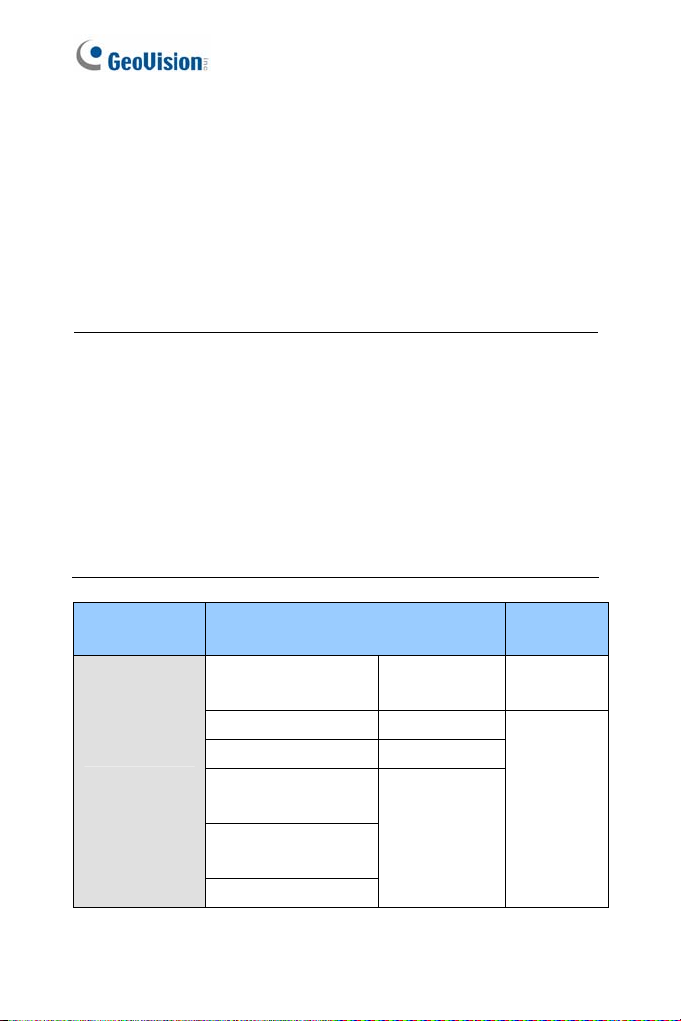
Model Model Number
Box Camera
upgrade.
120D / 130D DW / 220D 320D
120 / 220
dels installed w a 32 MB NA
GV-BX120D
GV-BX140DW
GV-BX130D-0 Varifocal Lens
GV-BX130D-1 Fixed Lens
GV-BX220D-2
GV-BX220D-3
GV-BX320D-0
GV-BX320D-1
GV-BX520D
rom V2.07 or earlier to the latest
amera’s storage device first
ed by fi
Varifocal Lens V2.15
Varifocal Lens
s and firmware
Firmware
Version
V2.14
vi
Page 9

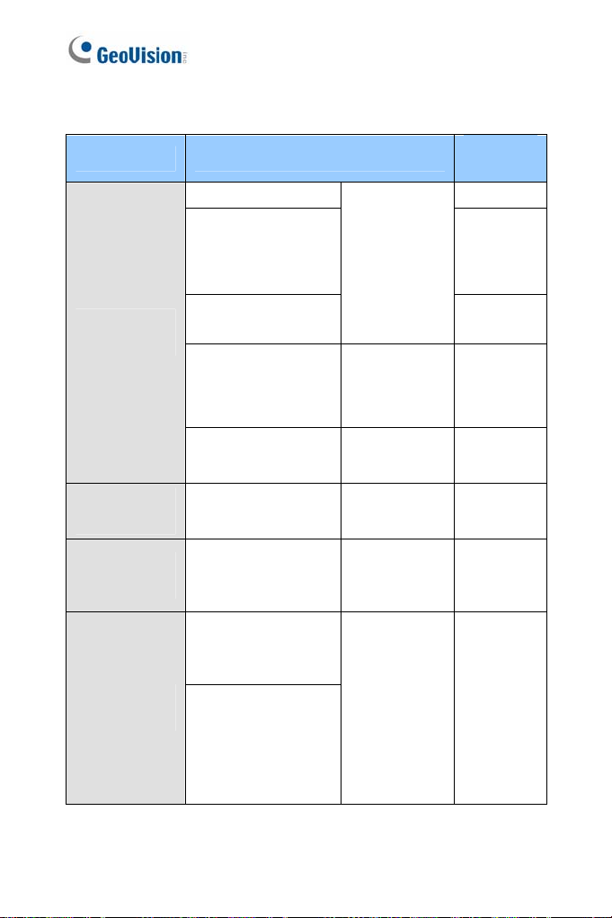
Model Model Number
Box Came
GV-BX120 F
GV-BX1
GV-B
GV-B
GV-B
GV-B
GV-BX1200-3V
GV-B
GV-B
GV-B
GV-BX2600
ra
GV-BX3400-5V
GV-B
GV-BX15
GV-BX2500-8F
GV-BX3400-8F
GV-BX5300-8F
GV-BX1500-3V
GV-BX2500-3V
GV-BX3400-3V
GV-BX5300-6V
GV-BX12201 Varifocal Lens
0-0F ~ 2
300-0F ~ 2F
X1500-1F ~ 2F
X2400-1F ~ 2F
X2500-1F ~ 2F
X3400-1F ~ 2F
X1300-3V
X1500-3V
X2500-3V
X5300-6V
00-8F
Fixed Lens
rifocal Lens
Va
Fixed Lens
P-Iris
Firmware
Version
V3.0
V1.0
V3.0
V3.0
Coming
V1.0
vii
Page 10
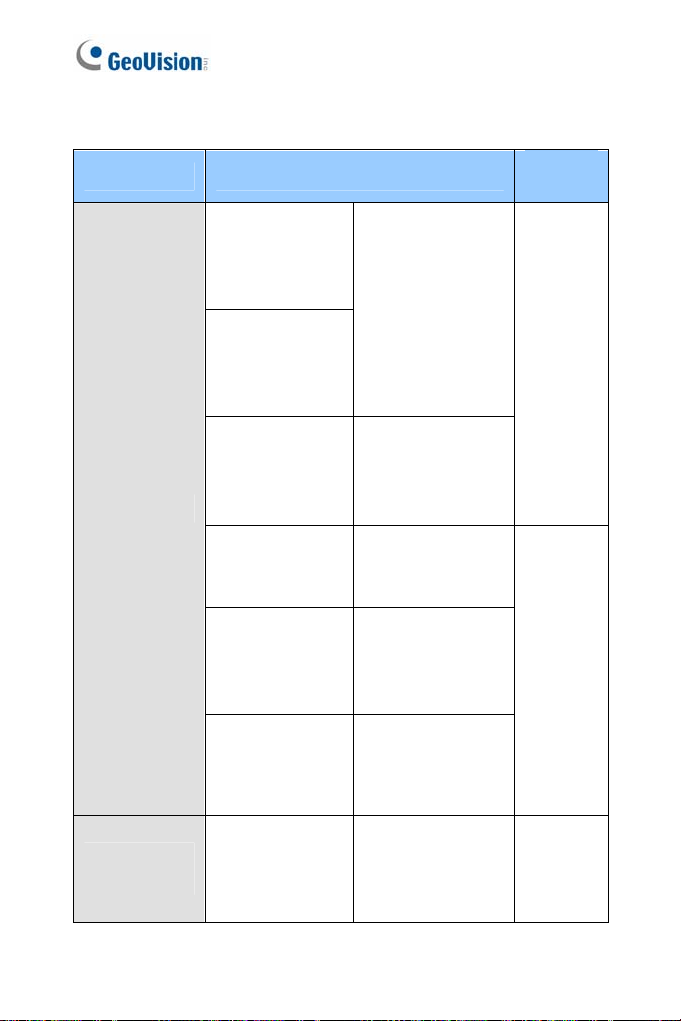
Model Model Number
GV-BX12
0D-E
Firmware
Version
V2.15
IR Arctic Box
Camera
Target Box
Camera
Ultra Box
Camera
Mini Fixed
Dome
GV-BX220D-E
GV
-BX320D-E
GV 0D-E
-BX52
GV-BX24
GV 00-E
GV-BX15
GV-BX
GV-BX2510-E
GV
GV
GV-EBX 100-2F
GV-UBX
GV-UBX
GV-UBX3301 Series
GV-MFD120
GV-MFD130
GV-MFD320
GV-MFD1501 Series
GV-MFD2401 Series
GV-MFD2501 Series
GV-MFD3401 Series
GV-MFD5301 Series
00-E
-BX53
00-E
3400-E
-BX5310-E
-EBX1100-0F
1
1301 Series
2301 Series
ifocal Lens
Var
torized
Mo
ifocal
Var
Lens, P-Iris
Motorized
Varifocal Lens
ed Lens
Fix
Fixed Lens
Fixed Lens
V2.14
V3.0
V3.0
(V3.03 or
later for PIris)
V3.0
V1.03
V3.0
V3.0
viii
Page 11

Model Model Number
2
320
-MDR
1500 Series
R es
Mini Fixed
Rugged D
ome
GV-MDR 20
GV-MDR
GV-MDR520
GV
GV-MDR3400 Series
GV-MD 5300 Seri
ed Lens
Fix
Firmware
Version
V3.0
Target Fixed
Dome
Target Mini
Fixed Dome
Target Mini
Fixed Rugged
Dome
GV-EFD2101
GV-EFD 101
3
GV-EFD1100 Series
GV-EFD2100 Series
GV-EDR1100 Series
GV-EDR2100 Series
focal Lens
Vari
Fixed Lens
V1.0
V1.03
Fixed Lens V1.03
ix
Page 12
Model Model Number
GV-BL120D
V-BL130D
G
V-BL220D
G
V-BL320D
G
GV-BL1500
V-BL2400
G
-BL2500
GV
V-BL
G 3400
Firmware
Version
Varifocal Lens
V3.0
Bullet Cam
Target Bullet
Camera
x
era
GV-BL1210
V-BL
G 3410
V-BL
5310
GV-BL
1501
-BL
2501
GV
GV-BL
3401
GV-BL1511
L2511
GV-B
L3411
GV-B
GV-BL5311
GV-BL2511-E
GV-BL5311-E
GV-EBL1100-1F
GV-EBL1100-2F
GV-EBL2100-1F
GV-EBL2100-2F
Motorized Varifocal
LeGns
Varifocal Lens,
P-Iris
Mo arifocal
torized V
Lens, P-Iris
Motorized Varifocal
Lens, extreme
temperature
tolerance, P-Iris
Fixed Lens V1.03
V3.01
Page 13

Model Model Number
GV-UBL1
GV
211
-UBL2411
GV-UBL3411
Ultra Bullet
Camera
GV-UBL1511
GV-UBL2511
GV-UBL1301 Series
GV-UBL2401 Series
GV-UBL3401 Series
Firmware
Version
Motorized
focal Lens
Vari
V3.0
Coming
Fixed Lens V3.0
xi
Page 14
Model Model Number
GV-VD120D
Vandal Proof
IP Dome
(IK10+, Tra
GV
(IK10+,
GV-VD122D
(IK7
GV-VD12
(IK7, Smok ver)
GV-VD220D
(IK10+, T
GV-VD221
(IK1
GV-VD22
(IK7, Trans
GV
(IK7, Sm
GV-VD320D
(IK
GV-VD321D
(IK10+, Smoked Cover)
GV-VD322D
(IK7, Transparent Cover)
GV-VD323D
(IK7, Smoked Cover)
GV-VD1500
GV-VD2400
GV-VD2500
GV-VD3400
nsparent Cover)
-VD121D
Smoked Cover)
, Transparent Cover)
3D
ed Co
ransparent Cover)
D
0+, Smoked Cover)
2D
parent Cover)
-VD223D
oked Cover)
10+, Transparent Cover)
Firmware
Version
Varifocal Lens V3.0
xii
Page 15

Model Model Number
GV-VD1530
-VD2430
GV
-VD2530
GV
-VD3430
Vandal Proof
IP Dome
IR Arctic
Vandal Proof
IP Dome
Target Vandal
Proof IP
Dome
PTZ Camera GV-PTZ010D
PT Camera
Advanced
Cube
Camera
GV
-VD1540
GV
D2440
GV-V
D2540
GV-V
GV-VD3440
D5340
GV-V
GV-V -E
D2540
GV
-VD5340-E
V-EVD2100
G
-EVD31
GV 00
GV-PT130D
GV-PT220D
GV-PT320D
GV-CA120
GV-CA220
GV-CAW120
GV-CAW220
Firmware
Version
Varifocal Lens,
high power IR
LEDs
Motorized
Varifocal Lens,
high power IR
LEDs
Mo
torized
V3.0
Varifocal Lens,
high pow
LEDs, extreme
tem
Va
NTSC
PAL
Fixed Lens
Fixed Lens
er IR
peratures
rifocal Lens V1.0
V1.09
V3.0
V3.0
x
iii
Page 16
Model Mo
Cube Ca
Fixed IP
Dom
e
Pinhole
Camera
del Number
-CB120
GV
V-CB220
G
GV-FD220D
-FD320D GV
GV-FD1200
GV
-FD1500
GV
-FD2400
GV
-FD2500
GV-FD3400
GV-FD1210
GV-FD1510
GV-FD2410
GV-FD2510
GV-FD3410
GV-UNP2500 Fixed Lens V3.03
Fixed Lens
Varifocal
Lens
Motorized
Varifocal Lens
Firmware
Version
V2.14 mera
V3.0
xiv
Page 17

Nam n ing and Definitio
GeoVision Analog and
oftware. The GV-System also ref
GV-System
GV-VMS GeoVision Video Management System for IP cameras.
S
System, GV-NVR System, GV-DVR System and GVHybrid DVR System at the same time.
Digital Video Recording
ers to GV-Multicam
xv
Page 18

Note for Connecting to GV-System / GV-VMS
The GV-IPCAM H.264 is designed to work with GV-System / GV-VMS, a
d or digital video management system. Note th
hybri
GV-IPCAM H.264 is connected to GV-System / G
1 By default, the images are recorded to the me
the GV-IP Camera H.264 (except GV-IR
Target Series, which are not equippe
2 Once the camera is connected to the GV-System / GV-VMS, the
resolution set on the GV-System / GV-VMS will override the
resolution set on the camera’s Web interface. You can only change
the resolution settings through the Web interface when the
connection to the GV-System / GV-VMS is interrupted.
d with a memory card slot).
e following when
V-VMS:
mory card inserted in
Arctic Box Camera and
xvi
Page 19

Note for Recording
1 By default, the images are recorded to the m
the GV-IP Camera H.264 (except GV-IR Arcti
Target Series, which are not equipped with a m
M
ake sure the Write recording data into
(see 3.1.1 Video Settings) is enabled. If this op
camera will stop recording to the memory c
accessed through Web browsers or other app
2 Mind the following when using
a memory card for recording:
Recorded data on the memory card
the data are accessed while the c
shock, power interruption, memory ca
the memory card reaches the end of its l
guarantee is provided for such cau
The stored data can be lost if the memory c
accessed for a long period of tim
periodically if you seldom access the m
Memo
ry cards are expendable and their durability varies
according to the conditions of the in
are used. Back up your data regularly and repl
ry card annually.
memo
emory card inserted in
c Box Camera and
emory card slot).
local storage option
tion is disabled, the
ard while the live view is
lications.
can be damaged or lost if
amera is under physical
rd detachment or when
ifespan. No
ses.
ard is not
e. Back up your data
emory card.
stalled site and how they
ace the
Replace the memory card when its read/write speed is lower
than 6 MB/s or when the memory card is frequently
undetected by the camera.
3 It is recommended to use memory cards of the following setting
and specifications:
Apply a battery backup (UPS) to avoid power outage.
Use Micro SD card of MLC NAND flash, Class 10 for better
performance.
xv
ii
Page 20

Note
Frame Rate
Mind the following restrictions, without rega
camera images, when the
1 The codec MJP
2 Dual streaming is not supported.
3 Video analysis function
4 TV-out is not supported.
5 The f
6 WDR Pro function is not supported.
7
Browser
For the users of Microsoft Internet Explorer, version 11 or later is
requi
browser.
for GV-BX2600
rd to the resolution of the
GV-BX2600 camera is set to 60 fps:
EG is not available in the main stream.
s, including motion detection, are not
supported.
rame rate will be dropped to 30 fps during live streaming and
recording when the camera starts monitoring.
1 or 2 fps will be dropped on the point of obtaining snapshots in
EG format with the CGI command.
JP
red to perform the GV-IPCAM H.264 operations through Web
Recording
When GV-BX2600 uses Micro SD card or USB HDD for recording, the
camera must not have more than one connection to GeoVision or third-
party software.
xviii
Page 21

Chapter 1 Introduction
The GV-IPCAM H.264 series
ameras for IP surveillance i
c
1.1 System Requir
To perform the
ensure
wing web browsers:
follo
Microsoft Internet Explorer 7.x or later
Google Chrome
Mozilla Firefox
Safari
Note:
1 For the users of Internet Explorer 8, additional settings are
2 For GV-B r 11 or later is required.
3 E browsers,
To access GV-BX12201 images, the PC spec should be met:
CPU Intel Core i5-4670, 3.40 GHz
GV-IPCAM H.264 operations through Web browser,
your PC is in good network connection, and use one of the
required. For details, see Appendix A.
With non-I
A. Mot Tampering Alarm, Visual Automation, Text
B. onl
C. RTSP streaming must be kept as enabled. For more detail,
X2600, Internet Explore
ion Detection,
Ov
rlay and two-way audio are not s
e upported.
the Play function is availabl
y e on the live view window
(Figure 19-3)
see 3.3.8 RTSP.
offers a comprehensive range of IP
n various environmental conditions.
ement
Memory DDR3 8 GB RAM
On Board Graphics
Intel HD Graphics 4600 (Versions of driver
from year 2014 or later required)
1
Page 22
access GV- 3100 images, the PC spec
To EFD3101 and GV-EVD
d be met:
shoul
CPU GHz Intel Core i5-4670, 3.40
Memory DDR3 4 GB RAM
On Board Graphics
Intel HD Graphics 4600 (Versions of driver
from year 2014 or later required)
2
Page 23

2
Chapter 2 Getting Started
Getting Started
This section provides the initial a
I
PCAM H.264.
2.1 Acc ng the Live V
Access or configu
firmware version:
Camera Type &
Firmware Versio
GV-IPCAM H.26
firmware V1.07 r later
(except GV-PTZ
essi iew
re amera according to the camera type and its
your c
n
4 with
o
010D)
Target Series
nd basic configurations of the GV-
Default Connection Type
DHCP
A
n unused IP addr
assigned by the D
camera when the ca
the network. Re
Dynamic IP Address to look up the IP
address.
However, if the camera is installed in a
LAN without DHCP server, access the
camera by its default IP address
192.168.0.10 and see 2.1.2 Configuring
the IP Address for more detail.
ess is automatically
HCP server to the
mera is connected to
fer to 2.1.1 Checking the
Note: By default, GV-PTZ010D is assigned with the fixed IP address
192.168.0.10.
3
Page 24
2.1.1 Checking the Dynamic IP Address
Follow the steps below to look up the IP address and access the Web
interface.
1. Install the GV-IP Device Utility program included on t
H.264 Software DVD.
he GV-IPCAM
Note: The PC installed with GV-IP Device Utilit
same LAN with the G
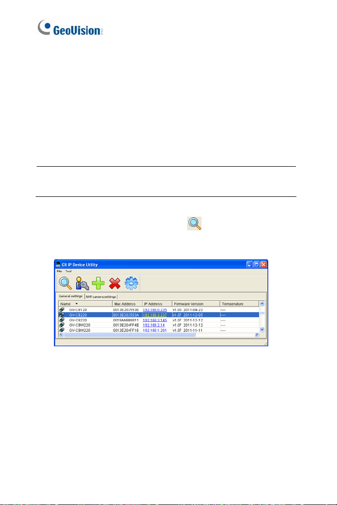
2. On the GV-IP Utility window, click the
IP devices connected in the same LA ck the Name or Mac
Address column to sort.
V-IPCAM H.264 you wish to configure.
Figure 2-1
y must be under the
button to search for the
N. Cli
4
Page 25
2
Getting Started
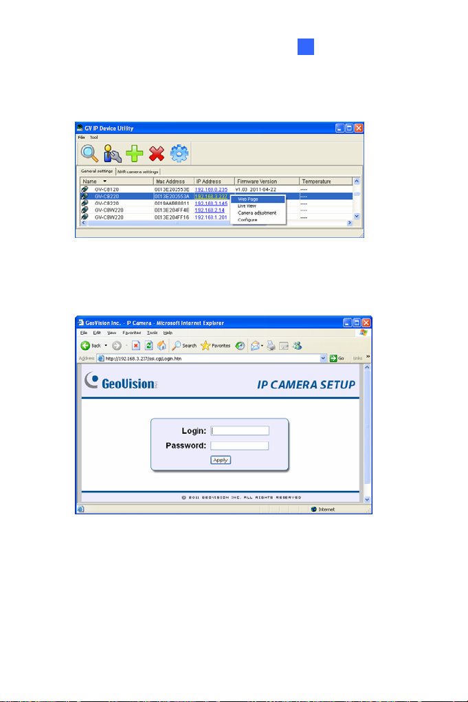
3.
Find the camera with its Mac Address, click on its IP address and
select Web Page.
Figure 2-2
4. The login page appears.
Figure 2-3
5. Type the default ID and password admin and click Apply to log in.
5
Page 26
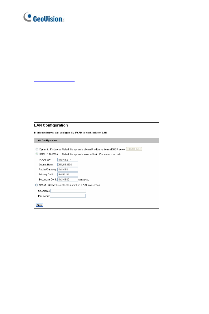
2.1.2 Configuring the IP Address
Follow the steps below to configure the IP a
1. Open
2. In both Login and Password fields, type the default value admin.
3. In the left menu, select Network and then LAN to begin the
your web browser, and type the default IP address
http://192.168.0.10
Click Apply.
network settings. This page appears.
.
ddress.
Figure 2-4
4. Select Dynamic IP address, Static IP address or PPPoE and
type the required network information.
5. Click Apply. The camera is now accessible by entering the
assigned IP address on the web browser.
6
Page 27

2
Getting Started
IMPORTANT:
1. If Dynamic IP Address or PPPoE is enabled
which IP address the camera will get from D
log in. If your camera is installed in the LAN,
Device Utility to look up its current dynamic IP
Checking the Dynamic IP Address. I
dynamic IP address via PPPoE, use the dyna
obtain a domain name that is
address first. For details on Dynamic IP Add
4.7.1 LAN Configuration and 4.7.3 Advanced
2. If Dynamic IP Address or PPPoE is enabled and you cannot
access the camera, you may have to reset it to the factory default
and then perform the network settings again.
To restore your camera to default settings, see Loading Factory
Default in the corresponding GV-IPCam H.264 Hardware Manual.
f your camera uses a public
linked to the camera’s changing IP
, you need to know
HCP server or ISP to
use the GV-IP
address. See 2.1.1
mic DNS Service to
ress and PPPoE, see
TCP/IP.
7
Page 28
2.1.3 Configuring the Wireless Connec
You may create wireless connection
Box Camera: GV-BX1200 series / 1300 series /
series / 2500 seri
es / 3400 series / 5300 series
to the Internet for:
tion
1500 series / 2400
Wireless Advanced Cube Camera: GV-CAW120/220
Mini Fixed Dome: GV-MFD
/ 3401 series / 5301 series
1. To set up the wireless
a standard network cable to the camera.
2. An IP addre
GV IP Device Utility to search for the device. For details, see 2.1.1
Checking the Dynamic IP Address.
3. Configure the wireless settings.
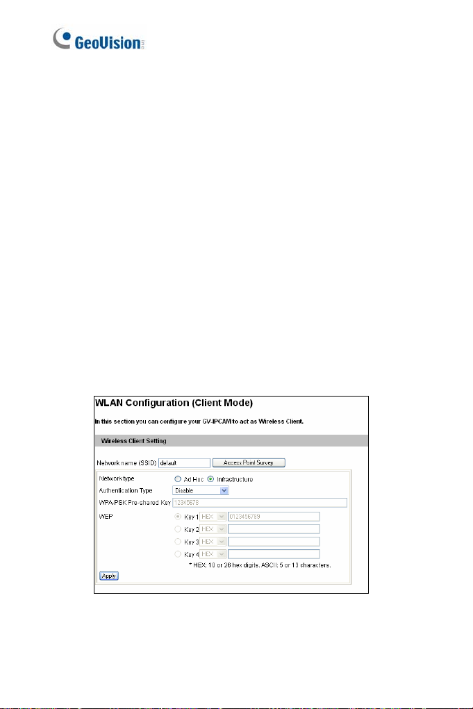
A. On the Web interface, select Network, select Wireless and
Client Mode. This dialog box appears.
ss will be automatically assigned to the camera. Use
1501 series / 2401 series / 2501 series
LAN for the first time, power on and connect
Figure 2-5
8
Page 29

2
Getting Started
B
. Type the Network Name (SSID) or click the Access Point
Survey button to search and select f
Points/wireless stations.
C. Select Ad
D. Select the Authentication Type using the
Sur
E. Type the WPA-PSK Pre-shared Key or WEP depending on the
encryption setting for the Access Point.
F. Click Apply to save the configuration.
Note:
1. Your encryption settings must match those used
Points or wirel
2. When Ad Ho c is used, only WEP encryption is supported.
3. When you lose the wireless access, you can still access the unit by
connecting it to a LAN and using the GV IP Device Utility to search
for the device.
4. For detailed information on configuring the wireless LAN, see 4.7.2
Wireless Client Mode.
-Hoc or Infrastructure for the Network type.
rcan also obtain this info
mation by clicking the Access Point
vey button.
ess stations with which you want to associate.
or the available Access
drop-down list. You
by the Access
9
Page 30
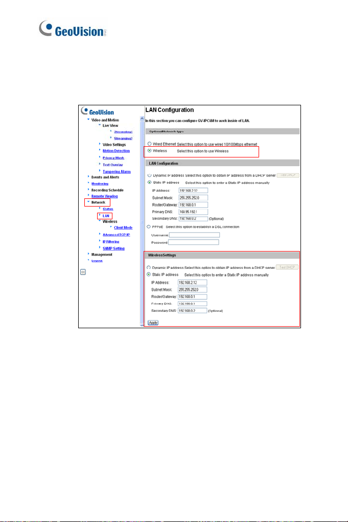
4. Enable wireless LAN.
A. On the Web interface, select Network and LAN. This page
appears.
Figure 2-6
B. Select Wireless for Optional Network Type.
C. To use a dynamic IP address assigned by the DHCP server,
select Dynamic IP address. To use a fixed IP address,
select Static IP address and type the IP address information.
10
Page 31

2
Getting Started
5
. Click Apply. The Camera will start creating a wireless connection
to the access point.
Note: For GV-CAW120
connection is established.
6. Unplug the Ethernet cable.
/220, the LAN LED turns blue when the
11
Page 32

2.2 Adjusting Image Clarity
Note the procedures described in this section only
IR Arctic Box Camera, Bullet Camera, PT C
Dome, Mini Fixed Dome, Mini Fixed Rugged Do
Fixed Dome, Target Mini Fixed Rugged Dome, and
To adjust focus of a PTZ camera, refer to Focus Adjustment in
c
orresponding GV-IPCam H.264 Hardware Manual
and Advanced Cube Came
Control Panel on the Live View Window.
ra, refer to Camera Adjustment in 3.2.2 The
apply to Box Camera,
amera, Vanda l Proof IP
me, Target Mini
Fixed IP Dome.
; for Cube Camera
After you have connected your GV-IPCAM H.264
the steps below to adjust image clarity.
to the network, follow
1. Make sure you have installed the GV-IP Devic
i
ncluded on the GV-IPCAM H.264
Note: The PC installed with GV-IP Device Utility must be under the
same LAN with the GV-IPCAM H.264 you wish to configure.
2. On the GV-IP Utility window, click the
IP devices co in the same LAN. Click the IP Address of the
camera you desire. A drop-down list appears.
nnected
Software DVD.
e Utility program
button to search for the
12
Figure 2-7
Page 33

2
Getting Started
3.
Select Focus Value. The Login dialog box appears.
Figure 2-8
4. Type the user name and password of the camera selected. The
default is admin for both user name and password. This window
appears.
Figure 2-9
13
Page 34

5. For IK10+ models (GV-VD120D / 121D / 22
321D / 1500 / 2400 / 2500 / 3400 / 1530
the supplied Focus Adjustment Cap over the
details, see 2.2.1 Using Focus Adjustmen
6. For Target Mini Fixed Dome and Target M ini Fixed R ugged
Dome, hold the camera cover close to the lens and use the
supplied focus adjustment tool for precise focus adjustment.
Figure 2-10
7. For Mini Fixed Dome and Mini Fixed Rugged Dome, hold the
camera cover close to the lens for precise focus adjustment. For
locations of adjustment screws and rings in each model, see 2.2.2
Locations of Adjustment Screws.
8. Adjust the Focus Screw and the Zoom Screw of the camera slowly
until the focus value reaches the maximum. For example, the
maximum focus value in Step 4 is 103. For locations of adjustment
screws in each model, see 2.2.2 Locations of Adjustment Screws.
0D / 221D / 320D /
/ 2430 / 2530 / 3430), hold
camera view. For
t Cap for details.
14
Page 35

2
Getting Started
Note:
1. Do not over tighten the screws. The screws only need to be as
tight as your fingers can get them to be. Do no
tool
to get them tighter. Doing so can damage the structure of
lens.
2. The maximum focus value may vary when the environment
changes.
t bother using any
15
Page 36

2.2.1 Using Focus Adjustment Cap
The Focus Adjustment Cap is only supplied for IK10+ models (GVVD120D / 121D / 220D / 22 / 2400 / 2500 / 3400
/ 1530 / 2430 / 2530 / 3430)
1D / 320D / 321D / 1500
.
Hold the Focus Adjustment
Cap on top of the camera view
and keep it close to the
ra. came
Do not leave a distance
between the Focus
Adjustment Cap and the
camera.
16
Page 37

2.2.2 Locations of Adjustment Screws
Models Adjust ment S cre ws
Box Camera
Bullet Camera
Vandal Proof IP Dome
2
Getting Started
Zoom Screw
Focus Screw
Zoom Screw
Focus Screw
Focus Screw
Zoom Screw
Fixed IP Dome
Focus Screw
Zoom Screw
17
Page 38

Models Adjustment Screws
GV-MFD120 / 130 / 320
Lens Screw
Focus Ring
GV-MFD1501 / 2401 /
3401 / 5301
GV-MDR220 / 320
GV-MDR1500 / 3400 /
5300
18
Focus Ring
Focus Ring
Lens Screw
Focus Ring
Page 39

2
Getting Started
Note:
1. The adjustment screws of Box Camera may vary f
models.
2. To focus GV-MFD
slowly adjust the focus ring. Some models may need a T6 screw
driver to loosen the camera lens. If you have a problem of
obtaining this type of screw driver, please contact our overseas
offices for further assistance.
and GV-MDR, loosen the lens screw first and
or different
19
Page 40

2.3 Configuring the Basics
Once the camera is properly install
can be configured using the browser-based c
discussed in the following sections in this man
Date and time adjustment: see 4.8.1 Date & Ti
Login and privileged passwords: see 4.8.3 Us
Network gateway: see 4.7 Network.
ed, the following important features
onfiguration page and are
ual:
me Settings.
er Account.
Camera image adjustment: see 3.2.2 The Control Panel of the Live
View Window
Video format, resolution and frame rate: see 4.1.1 Video Settings.
.
20
Page 41

3
Accessing the Camera
Chapter 3 Accessing
Two types of users are allowed to log on to
Administrator and Guest. The Administrator has full access to all
s
ystem configurations, while the Guest can only a
(except the Camera Adjustment settings) and n
3.1 Accessin
Once installed, your GV-IPCAM
Follow these steps to access your surveillance images:
1. Start your web browser.
2. Enter the IP address or the domain name of the camera in the
Location/Address field of your browser.
g Your Surveillance Images
H.264 is accessible on a network.
the Camera
the GV-IPCAM H.264:
ccess the live view
etwork status.
3. Enter the login name and password.
Figure 3-1
The default login name and password for Administrator are
admin.
The default login name and password for Guest are guest.
21
Page 42

4. Click Apply. A video image, similar to the example on Figure 3-2,
is now displayed in your browser.
Note: To enable the updating of images in Internet Explorer, you must
set your browser to allow ActiveX Controls and perform a once-only
installation of GeoVision’s ActiveX component onto your computer.
22
Page 43

3
Accessing the Camera
3.2 Functions Featured on the
This section introduc
Netw
ork Status on the
both Administrator and Guest.
Ma of Guest Mode
in Page
ideo and Motion
▼
V
► Live View
► Camera
▼ Network
► Status
The GV-IPCAM H.264 can process one video stream in two different
codec and image settings. In the Administrator mode, both streams are
available. Click Streaming 1 or Streaming 2 in the left menu to access
the live view. In the Guest mode, only one stream is available, as shown
in Figure 3-2.
es the features of the Live View window and
main page. The two features are accessible by
Main Page
Figure 3-2
23
Page 44

3.2.1 The Live View Window rnet Ex
Inte
When accessing the live view using Internet Explorer, the following
window appears.
1 2 3
plorer
5 6 7
4
Figure 3-3A
8
9
10
11
24
Page 45

3
Accessing the Camera
13
12
Figure 3-3B
25
Page 46

No. Name Function
1 Play Plays live video.
2 Stop Stops playing video.
Broadcasts to the surveilla
remote PC. Note this f
for Ultra Bullet Camera and
For Cube Camera and Advanced Cube
3 Microphon
4 Speaker
5 Snapshot
6 File Save
7 Full Screen
e Camera, you can click the
(from the pop-up menu) f
switch between audio tran
reception, where only one part
time.
Transfers sounds o
remote PC. Note this f
for GV-MFD120D / 130D /
Rugged Dome, Ultra B
Bullet Camera, and Targ
Rugged Dome, and Pi
Takes a snapshot of li
--- See 3.2.3 Snapshot of Live Video.
Records live video to the local computer.
--- See 3.2.4 Video Recording.
Switches to full screen view. Right-click the
image to have these options: Snapshot, Full
Screen, Resolution, Zoom In, Zoom Out, PIP
and PAP.
--- See 3.2.5 Picture-in-Picture and Picture-
and-Picture View for PIP and PAP views
nce site from a
unction is not available
Target Series.
Push to talk button
or the camera to
smission and
y can speak at a
f the surveillance site to a
unction is not available
320D, Mini Fixed
ullet Camera, Target
et Mini Fixed
nhole Camera..
ve video.
26
Page 47

No. Name Function
Displays the camera in
settings, audio data rate
8 Control P
Show Sy
9
Menu
10 PTZ Control Panel
11 I/O Control
12 LED Control
anel
stem
images captured upon alar
location of the camera
adjust image quality an
from the hard drive
Brings up the
and Audio Configurat
Show Camera Name an
--- See 3.2.6 Alarm Noti
3.2.7 Video and Audio Con
3.2.
8 Remote Configuration,
3.2.9 Camera Name Di
3.2.11. Image E
Enables the PTZ Control
PTZ. Note this func
Camera an
supported by GV-IP Cam
varifocal lens.
--- See The PTZ Control
H.264 Hardware Manual)
--- See 3.2.11 Visual PTZ
Enables the I/O Control Panel or the Visual
Automation. Note this function is only
supported by cameras with I/O function.
--- See 3.2.13 I/O Control.
Click to turn the Alarm LED on and/or adjust
the brightness sensitivity. Note this function is
only available for Advanced Cube Camera.
3
Accessing the Camera
formation, video
, I/O device status,
m, and GPS
. Also allows you to
d install the program
.
se functions: Alarm Notify, Video
ion, Remote Config,
d Image Enhance.
fication,
figuration,
splay, and
nhancement.
Panel or the Visual
tion is supported by PTZ
d PT Came
ra, and only partially
eras with motorized
Panel (GV-IPCam
27
Page 48

No. Name Function
Click to sound the alarm
volume.
13 Alarm Speaker
To sound t
events, see 4.3.9 Speaker for setup steps.
Note this function is only available for
Advanced Cube Camera.
and/or adjust its
he alarm upon motion or tampering
28
Page 49

3
Accessing the Camera
Non-IE Browsers
When accessing the live view using Google Chrome, Firefox or Safari,
this window appears. Note the following functions are not supported on
non-IE browsers: Motion Detection, Tampering Alarm, Visual
Automation, Text Overlay and Two-Way Audio.
Figure 3-4
29
Page 50

3.2.2 The Control Panel of the Live View
To open the control panel of the Live View
button on top of the window. You can access the following functions by
using the right and left arrow buttons on the control panel.
Click the arrow button to
display the control panel.
window, click the arrow
Click the right and left
arrow buttons to change
the page of the control
panel.
Window
Figure 3-5
Tip: Administrator may also access live view and camera adjustment
settings using the GV-IP Device Utility:
30
Page 51

3
Accessing the Camera
[
Information] Displays the version of the camera, time of the local
computer, time of the camera (host time), the nu
the camera and the OCX registration path.
[Video] Displays the current video codec, resoluti
[Audio] Displays the audio data rates when the
speaker devices are enabled.
[I/O Control] Note this function is only supported
function. Provides a real-time graphic display of t
status. You can force the output to be triggered by
icon.
[Alarm Notify] Displays the captured
motion detection. For this function to work, you have
Alarm
Notification settings first. See 3.2.6 Alarm Notification.
[Camera Adjustment] Allows you to
Click Save to store the changes to the settings. No
only accessible for Administrator.
Brightness: Adjusts the brightness of the image
Contrast: Adjusts the relative differe
next.
Saturation: Adjusts the saturation of the image
Sharpness: Adjusts the sharpness of the im
Gamma: Adjusts the relative proportions of bright and dark areas
White balance: The camera automatically adjusts the color to be
closest to the image you are viewing. You can choose one of the four
presets: Auto, Outdoor, Indoor, and Fluorescent. You can also
choose Manual to adjust the white balance manually.
Fli cker less: The camera automatically matches the frequency of
your camera’s image to the frequency of indoor light sources, e.g.
fluorescent lighting. You can also select 50 Hz or 60 Hz manually. If
these don’t match, faint light and dark bars may appear in your
images by sensor triggers and
adjust the image quality settings.
mber of users logging in
on and data rate.
microphone and
by cameras with I/O
he input and output
double-clicking its
to configure the
te that this function is
.
nces between one pixel and the
.
age
31
Page 52

images. Check the power utility to determine
us
ed.
Im age Orientation: Changes the image orient
View window.
Sl ow est Shutter Speed: Shutter speed control
lights enters the image sensor and directly im
image presentation. A slow shutter speed allow
exposure that creates a brighter overall ima
objects and bringing out background details
speed lowers col
The minimum shutter speed ranges from 1/5 to
light conditions, a fast shutter speed will lower co
image clarity. In this case, select the Auto opti
shutter control or select Auto (High Speed Mo
automatic shutter control.
D/N: Select Auto for automatic switch between d
mode depending on the amount of light detected.
white to switch the camera to night mode. Select
camera to day mode. Sets the light sensor’s s
between day mode and night mode. The value
sensitive. For details, see D/N, Special View Se
s.
Setting
Denoise: Reduces image noise especially under low-light conditions.
The higher the denoise value, the stronger the effect.
Wide Dynamic Range: adjusts and generates clear live view when
the scene contains very bright and very dark areas at the same time.
Select Auto (Strong) to bring out details in the darks areas of the
scene, select Auto (Weak) to bring out less detail in the dark area
and at the same time keep the bright areas from overexposure, or
select Auto (Normal) for a balanced effect. Select Close to disable
the function.
or and image clarity in order to capture motions.
which frequency is
ation on the Live
s the amount of the
pacts the quality of
s higher light
ge by blurring moving
, and a faster shutter
1/8000 sec. In low
lor quality and
on for automatic
de) for a faster
ay mode and night
Select Black and
Color to switch the
ensitivity of switching
10 is the most light-
ttings, 4.1.1 Video
32
Page 53

3
Accessing the Camera
D
efog: Select Auto to automatically enhan
Select Close to disable the function.
Super Low Lux: Select Auto for the c
enhance the live view under insufficient light. S
the function. The default setting is Auto
Low Lux Enhancement: Select Auto for the ca
automatically enhance the live view under insu
Close to disable the f
Zoom: Click the Zoom In
apparent distance of the scene. After zooming the camera, re-
the
focus the camera manually or automatically. F
Change and Focus Mode below.
Focus Change: Click the Focus In
o adjust the focus. To focus automatically, c
t
but
ton.
Focus Mode: Select Normal Scan, Regional Scan
and then click the Start
camera focus. The Normal Scan mode focu
fastest. The Regional Scan mode focuses the
live view. The Full Scan mode performs a det
applies the best focus.
Day Night Focus: Saves foc
mode. Select Auto to automatically focus. Select Close to disable
the Day Night Focus function. To configure fixed settings for day
mode and night mode, select Manual and follow the steps below:
1. Make sure the D/N is in Auto mode for the best effect. The
following focus setting will be applied to the current D/N mode.
2. Adjust the focus using the Focus In
buttons and/or the Focus Mode function.
3. Click Day Mode Save
depending on the current D/N mode.
unction. The default setting is Auto.
and Zoom Out
button to automatically adjust the
us settings for day mode and night
or the Night Mode Save
ce the visibility of images.
amera to automatically
elect Close to disable
.
mera to
fficient light. Select
buttons to adjust
or details, see Focus
and Focus Out
lick the Auto Focus
or Full Scan
ses the camera the
area selected on the
ailed checkup and
and Focus Out
buttons
button
33
Page 54

Metering: Controls the camera’s exposure. Se
camera to adjust exposure based on the full liv
Regional Metering for the camera to adjust ex
zones. Draw directly on the live view and a b
(automatic exposure)” appears. You can establish up to 4 zones. To
remove the block, right-click the block and select Delete.
[Download] Allows you to install the programs from the hard drive.
lect Normal for the
e view. Select
posure of specified
lock marked with “AE
34
Page 55

3
Accessing the Camera
Figure 3-6B
Figure 3-6C
Figure 3-6A
35
Page 56

Note:
1. For GV-PTZ010D, Brightness, Contrast,
Sharpness, D/N, Slowest Shutter Speed, Wide D
Range and Defog are not available.
2. For GV-BX140DW, Slow est Shutter Spee
Range and Defog are not available. D/N sensi
is not available and GV-BX140DW will aut
with its built-in light sensor.
3. For GV-BX2600, Backlight Compensatio
Range, Defog, Super Low Lux, Denoise,
available. The WDR setting for GV-BX2600 i
page (see Figure 4-2A, 4.1.1 Video Set
4. Zoom, Focus Change, Focus Mode and
settings are only available for models with
lens.
5. Super Low Lux setting is only available for models with a super
low lux CMOS sensor.
6. Low Lux Enhancement is currently only available for GVBX12201.
7. Denoise and Metering settings are only available for firmware
V2.14 or later.
Saturation,
ynamic
d, Wide Dynamic
tivity adjustment
omatically detect light
n, Wide Dynamic
Metering are not
s in Video Setting
tings).
Day Night Focus
motorized varifocal
36
Page 57

3
Accessing the Camera
3.2.3 Snapshot of Live Video
To take a snapshot of live video, follow these steps
1. Click the Snapshot button (No. 5, Figure 3-3)
box appears.
2. Specify Save in, type the File name, and select JPEG or BMP as
Save as Type. You may also choose whet
and date stamps
3. Click the Save button to save the image in the local computer.
: GV-BX12201 only supports snapshots in Stream 2 with the
Note
maximum resolution of 1 MP.
on the image.
:
. The Save As dialog
her to display the name
3.2.4 Video Recording
You can record live video for a certain period o
computer.
1. Click the File Save button (No. 6, Figure 3-3). The Save As dialog
box appears.
2. Specify Save in, type the File name, and move the Time Peri od
slider to specify the time length of the video clip from 1 to 5 minutes.
3. Click the Save button to start recording.
4. To stop recording, click the Stop button (No. 2, Figure 3-3).
f time to your local
37
Page 58

3.2.5 Picture-in-Picture and Picture-an
The full screen mode provides two types of c
icture (PIP) and Picture-an
P
to provide clear and detailed images of the survei
d Picture (PAP). The two views are useful
d-Picture View
lose-up views: Picture-in-
llance area.
Picture-in-Picture View
With the Picture in Picture (PIP) view, you can crop the video to get a
close-up view or zoom in on the video.
Navigation box
Inset window
Figure 3-7
Right-click the live view and select PIP. An inset window appears.
1.
2. Click the insert window. A navigation box appears.
3. Move the navigation box around in the inset window to have a
close-up view of the selected area.
4. To adjust the navigation box size, move the cursor to any of the
box corners, and enlarge or diminish the box.
5. To exit the PIP view, right-click the image and click PIP again.
38
Page 59

3
Accessing the Camera
Picture-and-Picture View
With the Picture and Picture (PAP) view, you can create a split video
effect with multiple close-up views on the image. A total of 7 close-up
views can be defined.
Figure 3-8
1. Right-click the live view and select PAP. A row of three inset
w
indows appears at the bottom.
2. Draw a navigation box on the image, and thi
immediately reflected in one inset window. Up
boxes can be drawn on the image.
To adjust a navigation box size, m3. ove the c
corners, and enlarge or
4. To move a navigation box to another area on the image, drag it to
that area.
5. To add more navigation boxes, to show or hide navigation boxes or
to change the frame color of the navigation boxes, right-click the
image, select Mega Pixel Setting and click one of these options:
diminish the box.
Enable Add-Focus-Area Mode: Allows the user to add more
navigation boxes on the image. This option is not available
when 7 navigation boxes have been drawn.
Display Focus Area of PAP Mode: Displays or hides the
navigation boxes on the image
s selected area is
to seven navigation
ursor to any of the box
39
Page 60

Set Color of Focus Area: Changes
frames.
6. To delete a navigation box, right-click the des
Focus Area of PAP Mode and click Delete.
7. To exit the PAP view, right-click the image and click PAP again.
the color of the box
ired box, select
40
Page 61

3
Accessing the Camera
3.2.6 Alarm Notification
After input triggers and motion detection, you can be alerted by a pop-up
live video and view up to four captured images.
Pop-up live
vi
deo
Captured
images video
Figure 3-9
configure this function, click the Show System Menu button (No. 9,
To
Figure 3-3), and select Alarm Notify. This dialog box appears.
Figure 3-10
Motion Notify: Once motion is detected, the captured images are
displayed on the control panel of the Live View window.
41
Page 62

I/O Alarm Notify: Once the input device is trigg
images are displayed on th
this function to work, the Administrator n
For
device properly. See 4.2.1 Input Setting.
Alert Sound: Activates t
triggered detection.
IE Window Pops up: The minimized
motion and input-triggered detection.
e control panel of the Live View window.
he computer alarm on motion and input-
Live View window pops up on
ered, the captured
eeds to install the input
Auto Snapshot: The snapshot of live video is taken every 5
seconds on motion and input-triggered detection.
File Path: Assigns a file path to save the snapshots.
42
Page 63

3
Accessing the Camera
3.2.7 Video and Audio Configurat
You can enable the microphone and speaker for tw
communication and adjust the audio volume. To change audio
c
onfiguration, click the Show System Menu butt
and select Video and Audio Configuration.
ion
o-way audio
on (No. 9, Figure 3-3),
Camera: Sets the number of frames to keep in live view buffer.
Keeping more frames for live view buffer can ensure a smooth live
view, but the live view will be delayed for the number of frames
specified.
Figure 3-11
43
Page 64

Audio Configure: You can enable the microphone and speaker,
and adjust the audio volume
Figure 3-12
44
Page 65

3
Accessing the Camera
3.2.8 Remote Configuration
You can upgrade firmware over the network. Click the Show System
Me
nu button (No. 9, Figure 3-3), and select Remote
Remote Config dialog box will appear.
[Firmware Upgrade] In th
Internet. For details, see Advanced Applications, Chapt
is tab, you can upgrade the firmware over the
Config. The
er 5.
3.2.9 Camera Name
To display the streaming name on the image, cl
Menu button
(No. 9, Figure 3-3), and select Show Camera Name.
Display
ick the Show System
3.2.10 Image Enhancement
To enhance the image quality of live video, click the Show System
Menu button (No. 9, Figure 3-3), and s lect Image Enhance. This
dialog box appears.
e
De-Interlace: Converts the interlaced video into non-interlaced
video.
De-Block: Removes the block-like artifacts from low-quality and
highly compressed video.
Enable DirectDraw: Activates the DirectDraw function.
Figure 3-13
45
Page 66

3.2.11 Visual PTZ
Note this feature is only available in PTZ Camera a nd PT Camera.
isual PTZ prov
The V
for easy and direct P Z operation.
ides two types of PTZ control panels on live images
T
Activating Visual PTZ
Click the PTZ Control button
PTZ. Alternatively right-click anywhere on the live view and select
Visual PTZ.
(No. 10, Figure 3-3) and select Visual
Visual PTZ
Control Panel
46
Figure 3-14
Page 67

3
Accessing the Camera
h TZ P ures:
T e Visual P anel provides the following feat
No. Name Description
1 Zoom In
2 Zo O
3 Focus In
4 Focus Out
5 Home Brings the camera to the home point.
6 Auto Focus
7 Preset Go
8 Go Sequence
9 Auto Pan
Figure 3-15
hortens the apparent distance between the
om ut
S
camera and the view.
Lengthens the apparent d
camera and the view.
Automatically adjusts the sharpness of the
camera view.
Starts a single movement in which the PTZ
Camera moves towards a point in live view.
Starts a series of movements in which the PTZ
Camera moves towards at least two Preset
points in live view.
Starts a horizontal movement of the PTZ
Camera in live view.
istance between the
of the camera view. Adjusts the sharpness
47
Page 68

Setting Visual PTZ Panel
Click the .button on the top left corner and select Visual PTZ, the
f
ollowing options will appear.
PTZ Control Type: Two types of visual PTZ c
available.
Type 1: Appears only when a movement o
detected and disappears when it is static.
cursor in one of the eight directions, i.e. u
up, left down, right up and right down, a 5-
Click and hold onto the required level to m
speed level is indic
Type 2: Appears with a click on the live vi
with the second click. As the cursor points t
directions, a 5-level a
is away from the visual PTZ control panel,
movement and vice versa. The speed l
top right corner of the live view.
ated at the top right corner of the live view.
rrow head appears. The further the arrow
Set Color: Changes the color of the arrow line and the speed
indicated at the top right corner of the live view. Alternatively, you
can right-click the live view (with Visual PTZ enabled). Three colors
are available: Red, Green and Blue.
Transparency: Changes the transparency level of the Visual PTZ
Control Panel. Ten levels range from 10% (fully transparent) to
100% (fully opaque).
ontrol panels are
f the cursor is
When you place the
p, down, left, right, left
level arrow appears.
ove the camera. The
ew and disappears
o one of the eight
the faster the
evel is indicated at the
48
Page 69

3
Accessing the Camera
3.2.12 Digital PTZ
Note this function is only supported by firmware V 2.06.
This function allows non-PTZ cameras to simulat
live view.
1. Right-click the live view and select Digital PTZ. The live view is
labeled with “DPTZ” at the top left corner.
Figure 3-16
2. To zoom in / out, move the cursor to the live view and click the
corresponding buttons. To bring the view back to its default image,
click Home.
e PTZ movements on
Figure 3-17
49
Page 70

3. To pan and tilt the view, zoom the image first a
hold the arrow on the image.
the cursor in one of the eight directions, i.e. up, down, left, right, left
up, left down, right up and right down.
4. To adjust the transparency level of the control panel, click the
green DPTZ button and select Transparency. Ten levels range
from 10% (fully transparent) to 100% (fully opaque) are available.
Note: The Focus In / Out and the speed level are not functional for
Digital PTZ.
The arrow appears when you place
Figure 3-18
nd then click and
50
Page 71

3
Accessing the Camera
3.2.13 I/O Control
Note this function is only supported by cameras wi th I/O function.
The I/O Control window provides a real-time graphic display of camera
status, I/O status, and alarm events. Additionally, you can remotely force
output to be triggered.
Figure 3-19
To display the I/O control window, click the I/O Control button (No.
11, Figure 3-3) and select I/O Control .
The Alarm List is displayed in three levels. The first level indicates
date, the second indicates time, and the third indicates alarm ID.
Clicking the Reset button will clear the list.
To trigger an output device, highlight an output and then click the
Output button.
51
Page 72

3.2.14 Visual Automation
Note this function is only supported by cameras w
The Visual Automation allows you to change the
electronic device by simply clicking on its image, e.g. turning the light
ON. This feature is only available when the Visual Automation is set
ahead by the Administrator. For details, see 4.1.6 Visual Automation.
ith I/O function.
current state of the
Figure 3-20
To access this feature, click the I/O Control button (No. 11, Figure 3-
3) and select Visual Automation.
To change the style of the set areas, click the green I/O button on the
top left corner. You will have these options:
Show All: Displays all set areas.
Rect Float: Embosses all set areas.
Set Color: Changes the frame color of all set areas
52
Page 73

3.2.15 Network Status
3
Accessing the Camera
To view the network status, in the left menu, click Net
Status.
Figure 3-21
work and select
53
Page 74

Chapter 4 Administrator Mode
The Administrator can access the system configuration through the
network. Eight categories of configurations are involved in the system
configuration: Video and Motion, I/O Control or Digital I/O an d PTZ,
Events and Alerts, Monitoring, Recording Schedule, Remote ViewLog,
Network and Management.
Figure 4-1
54
Page 75

4 4
Administrator Mode
of Menu Options
List
Find the topic of interest by referring to the corresponding section listed
below. The available options may vary among camera models.
4.1.1 Video Settings
4.1.2 Motion Detection
4.1 Video and Motion
4.2 Video Analysis
4.3 Digital I/O and PTZ
4.4 Events and Alerts
4.5 Monitoring
4.6 Recording Schedule
4.7 Remote ViewLog
4.1.3 Privacy Mask
4.1.4 Text Overlay
4.1.5 Tampering Alarm
4.1.6 Visual Automation
4.2.1 Motion Detection
4.2.2 Advanced Video Analysis
4.2.2.1 Intruder
4.2.2.2 People Count
4.2.2.3 Loitering
4.2.3 Unattended Object / Missing
Object Detection
4.2.4 Tampering Alarm
4.3.1 Input Settings
4.3.2 Output Settings
4.3.3 PTZ Settings
4.4.1 Email
4.4.2 FTP
4.4.3 Center V2
4.4.4 Vital Sign Monitor
4.4.5 Backup Center
4.4.6 Video Gateway/Recording Server
4.4.7 ViewLog Server
4.4.8 RTSP/ONVIF
4.4.9 Speaker
4.6.1 Camera
4.6.2 I/O Monitor
55
Page 76

4.8 Network
4.9 Management
4.8.1 LAN
4.8.2 Wireless-Client Mode
4.8.3 Advanced TCP/IP
4.8.4 UMTS Settings
4.8.5 IP Filtering
4.8.6 SNMP Settings
4.9.1 Date and Time Settings
4.9.2 Storage Settings
4.9.3 User Account
4.9.4 Log Information
4.9.5 Tools
4.9.6 Language
56
Page 77

4 4
Administrator Mode
4.1 Video and Motion
The GV-IPCAM H.264 can simultaneously process one video source in two
different codec and resolutions. The dual-stream design benefits for lower
bandwidth environment, allowing Streaming 2 to be set with lower
resolution and codec for live streaming, and Streaming 1 set with highest
resolution and codec H.264 for best recording quality. Two setting pages
Streaming 1 and Streaming 2 are provided for separate setup.
Comparison between Streaming 1 and Streaming 2:
Video Setting Options Streaming 1 Streaming 2
Watermark Setting
Audio in Source
Special View Setting
Video Resolution
Audio Settings Yes No
TV Out Yes
Note:
1. Audio In Source is only available in GV-PTZ010D.
2. Audio Settings is not available for GV-PTZ010D.
3. TV Out is only available for Box Camera, IR Arctic Box Camera,
Vandal Proof IP Dome and Fixed IP Dome.
This section includes the video image settings and how the images can be
managed through Motion Detection, Privacy Mask, Text Overlay,
Tampering Alarm, and Visual Automation.
Yes
Yes. Different resolutions can be applied to
Streaming 1 and Streaming 2.
Not open for configuration.
But settings in Streaming 1
are automatically applied to
Streaming 2
No
57
Page 78

4.1.1 Video Settings
58
Figure 4-2A
Page 79

4 4
Administrator Mode
Figure 4-2B
59
Page 80

Figure 4-2C
[Name] Rename the video stream. To display the name of video stream on
the Live View window, see 3.2.9 Camera Name Display.
[Connection Template] Select the type of your network connection.
Unless you select Customized, this option will automatically bring up the
recommended video resolution, frame rate, bandwidth and GOP size.
[Video Signal Type ] S el ect the video signal type, resolution and frame
rate. Select between H.264 and MJPEG as the codec type. For details on
the resolutions and frame rates of each camera model, see Appendix B.
60
Page 81

4 4
Administrator Mode
Not
e that for all the cameras (except GV-PTZ010D), the resolution options
available for sub stream vary with the resolution selected for its main
stream. For example, if a 4:3 resolution is selected for the main stream in
GV-BX320D-0, two options, 640 x 480 and 320 x 240 will be available for
its sub stream.
Note: The Hardware WDR Support option (see Figure 4-2A) is only
available for GV-BX2600. It produces clear live view when the scene
contains very bright and very dark areas at the same time. This function
is enabled by default. However, you will be prompted to disable the
function when the camera records up to 60 frames per second.
For WDR Pro or WDR option of other cameras, see Camera Adjustment
in 3.2.2 The Control Panel on the Live View Window to adjust the setti ng.
[Bandwidth Management] When using the H.264 codec, it is possible to
control the bitrate, which in turn allows the amount of bandwidth usage to
be controlled.
VBR (Variable Bitrate): The quality of the video stream is kept as
constant as possible at the cost of a varying bitrate. The bandwidth is
much more efficiently used than a comparable CBR.
Set the image quality to one of the 5 standards: Standard, Fair,
Good, Great and Excellent.
Maximal Bit Rate: When the actual bitrate exceeds the specified
Maximal Bit Rate, the sy stem will automatically lower its bitrate so as
not to exceed it. Select one of the bitrates from the drop-down list or
select Auto i f you do not want to enable this function. The default
maximal bitrate values are detailed as follows:
61
Page 82

Camera Type Default Max. Bitrate of VBR
1.3 MP
2 MP
3 MP / 4 MP / 5 MP
8 MP / 12 MP
Note: For GV-BX2600, the default maximum bitrate for Stream 1 is set to
6 Mbit. When the video format of Stream 1 and 2 is set as MJPEG, the
options for bitrate setting will be hidden automatically.
CBR (Constant Bitrate): CBR is used to achieve a specific bitrate by
varying the quality of the H.264 stream. Select one of the bitrates from
the drop-down list.
[Region of Interest] Note this function is disabled by default and is not
supported by GV-BX2600. Sets ROI (clarity) to specified regions on the
live view for standalone GV-IP Cameras, GV-IP Cameras connecting to
GV-System / GV-VMS or third-party software through ONVIF/RTSP. A total
of 5 ROI can be set. This function is disabled by default.
Stream 1 6 Mbit
Stream 2 4 Mbit
Stream 1 8 Mbit
Stream 2 4 Mbit
Stream 1
Stream 2
Stream 1
Stream 2
12 Mbit
16 Mbit
62
Page 83

4 4
Administrator Mode
Select Enable and click ROI Setting to configure:
1. On the popup window, use your mouse and draw directly on the live
view to specify a region.
Figure 4-3
2. To set up a region with enhanced clarity, select ROI, select High,
Medium or Low using the drop-down list and then drag on the
image to outline a region.
3. Click Apply to apply the configurations.
[GOP Structure and Length] Set the maximum number of seconds
between every key frame.
63
Page 84

[Video Slice Mode] Note this function is only supported by firmware V2.12
or earlier and is not supported for Target Series. Corrects the display
mode of the camera when it is displayed on a third-party NVR/DVR
software and the live view is incomplete or broken. Select Single Slice or
Multi Slice to display the live view. The default is Auto.
[H.264 Video Entropy Coding Setting]
By default, the entropy coding is set to CAVLC. To change it to CABAC,
click and select from the drop-down list.
Note: GV-BX12201 currently does not support H.264 Video Entropy
Coding Setting.
[Record Settings] The alarm settings allow you to capture images before
and/or after the motion or I/O events happen.
Pre-alarm recording time: Activates video recording before an event
occurs. Set the recording time to 1 or 2 seconds. The recording is
saved in the buffer of the camera.
Post-alarm recording time: Activates video recording onto the
inserted memory card after an event occurs. Set the recording time
from 1 to 30 seconds.
Split-interval (Max. Video Clip): Sets the maximum time length of
each recorded file from 1 to 5 minutes.
Record Profile: Note this function is only available for firmware V2.14
or later. This setting is only applicable for recording to the camera’s
memory card. Select Performance to maximize the lifespan of the
memory card by restricting the maximum bit rate to 4 Mbit and
Sharpness value to 30. Select Quality to adopt your current settings.
Record audio: Activates audio recording when an event occurs.
Write recording data into local storage: Select this function for
uninterrupted recording to the memory card while the live view is
64
Page 85

4 4
Administrator Mode
ac
cessed through the Web interface or other applications. This option
is enabled by default.
IMPORTANT: To ensure the quality of simultaneous recording and live
view access, make sure you connect no more than two connections to
the camera using Web interface or any other applications.
[Text Overlay Settings] Displays camera name, date, and/or time on the
live view and recorded videos when viewing through GeoVision software.
Camera Name: Type the camera name.
Overlay with: Select one or more of the options below to be overlaid
on the live view and recorded videos.
Camera Name
Date
System Time
Name of the Associated Digital Input: Note this option is only
supported by cameras with I/O function.
[Text Overlay Settings (OSD)] Note this function is not supported by GVBX2600. Displays camera name, date, and/or time on the live view and
recorded videos when viewing through GeoVision software and third-party
software through ONVIF and RTSP.
Name: Type the camera name.
Font Size: Select the font size using the drop-down list.
Overlay with: Select one or more of the options below to be overlaid
on the live view and recorded videos. Use the drop-down list to select
the display position.
Camera Name
Date
65
Page 86

System Time
[Watermark Setting] Note this function is not supported for Target Series.
Enable this option to watermark all recordings. The watermark allows you
to verify whether the video has been tampered while it was recorded. See
6.4 Verifying Watermark.
[Audio In Source] Note this function is only available in GV-PTZ010D
which contain a built-in microphone and also allow you to install an external
microphone.
Built-in Microphone: Enable the built-in microphone to record
sounds. By default the option is enabled.
External Microphone: Enable the externally connected microphone
to record sounds.
[TV Out] Note this function is only available for Box Camera, IR Arctic
Box Camera, Vandal Proof IP Dome, Fixed IP Dome, Target Mini Fixe d
Dome (EFD2101/3101) and Target Vandal Proof IP Dome
(EVD2100/3101). Select the signal format of the Video Output on the
camera as either NTSC or PAL.
Note:
1. For smooth display of Box Camera, IR Arctic Box Camera, Fixed
IP Dome and Vandal Proof IP Dome on m onitor, the video
resolution must be 1280 x 1024 or lower. If dual streams are
enabled, the sub stream must be set as 640 x 480 The D/N settings
are not available for GV-BX140DW.
2. The resolution of GV-EFD2101/3101 and GV-EVD2100/3100 on
monitor is universally set to D1.
66
Page 87

4 4
Administrator Mode
[
LED Control] Note this function is not available in GV-PTZ010D.
Ready LED: Select Disable if you do not wish to use the Status LED.
LAN LED, WAN LED, Monitoring LED: Note this option is only
available in Advanced Cube Camera. Select Disable if you do not
wish to use the LEDs. For details on LED status, see Overview in the
corresponding GV-IPCam H.264 Hardware Manual.
Ala rm LED: Sets the white illumination LED in Advanced Cube
Camera. The LED is enabled by default.
Auto: Select Auto for the white illumination LED to illuminate the
scene automatically when the PIR sensor detects any motion
within 5 meters.
Sensitivity: Set the sensitivity for low light detection. The higher
the value, the easier the white illumination LED is to be triggered.
The default value is 5.
The Interval between triggering: Select the duration for the white
illumination LED to light up at full intensity. If a motion persists
over the specified period, the white illumination LED will light up
with less intensity. This option is designed to keep the camera
temperature within its precautious range. The default value is 60
seconds.
Off: Select to disable the white illumination LED.
[Special View Setting] Note this function is not available in GV-BX2600.
D/N: Sets the sensitivity of day-night mode switch. The higher the
sensitivity value, the more sensitive the switch is from day mode to
night mode. The default value is 5.
Auto: Select Auto for the camera to detect the amount of light
present and automatically switch to monochrome in a poorly-lit
scene. Move the slider to adjust the sensitivity level from 0 to 10.
Black and White: Select this option for the live view to be in
monochrome.
67
Page 88

Color: Select this option for the live view to be in color.
IR Check Function: Note this option is only available for Box
Camera (except GV-BX2600). This function determines whether the
surveillance area is illuminated by an externally installed infrared
illuminator.
Off: The default setting. The infrared illuminator will be constantly
off. It is advisable to enable this option when the color temperature
of outdoor lighting is 6000 K or above.
On: The infrared illuminator will be constantly on.
Trigger by Input / Trigger IR by D/N: Select this option for the
infrared illuminator to turn on under low light and turn off under
sufficient light.
Note:
1. The D/N settings are not available for GV-BX140DW.
2. If an infrared illuminator is installed for outdoor surveillance, it is
suggested to use the Trigger by Input or the Trigger IR by D/N
function to avoid incorrect judgment of lighting and hence the action
of the IR cut filter. See Infrared Illuminators in the GV-IPCam H.264
Hardware Manual.
3. If you select Trigger by Input / Trigger IR by D/N option, make
sure you have set D/N as Auto and configured its sensitivity level.
Iris Type: Note this function is not supported for GV-IP Cameras with
fixed lens or fixed iris. This field shows the iris type (DC-Iris or P-Iris)
of your GV-IP Camera.
Auto Iris: The option is designed for auto iris lens (DC-Iris or P-
Iris). Enable the auto iris function when the scene appears fuzzy
and the Flicker Less function does not help to improve the
situation.
68
Page 89

4 4
Administrator Mode
BLC: Note this function is not supported by GV-BX140DW and GV-
BX2600. Select On to enable Backlight Compensation (BLC). This
function is used to adjust the color intensity of scenes with strong light
at the background.
Note: To access the BLC function in PTZ camera, see Other, Image
Settings in the GV-IPCam H.264 Hardware Manual.
IR Light: Note this function is only available for Target Series, Ultra
Box Camera, IR Arctic Box Camera, Bullet Camera, Ultra Bullet
Camera, PT Camera, Vandal Proof IP Dome and Fixed IP Dome.
Select Auto for automatic switc h between day mode and night mode
depending on the amount of light detected. Select Off to completely
disable IR LEDs.
69
Page 90

4.1.2 Motion Detection
Motion detection is disabled by default except for GV-PTZ010D.
Note: GV-BX2600 has its independent motion detection setting. For
details, see 4.2 Video Analysis.
Motion detection is used to generate an alarm whenever movement occurs
in the video image. You can configure up to 8 areas with different
sensitivity values for motion detection. Set up at least one area to enable
this function.
Figure 4-4
70
Page 91

4 4
Administrator Mode
1.
Select the desired sensitivit y by moving the sli der. There are t en
values. The higher the value, the more sensitive the camera is to
motion.
2. Drag an area on the image. Click Add when you are prompted to
confirm the setting.
3. To create several areas with different sensitivi ty values, repeat steps
1 and 2.
4. Click Save to save the above settings.
5. Click Reset to delete all the selected areas.
6. If you want to detect motion using the PIR sensor (for Advanced
Cube Camera only), select Use PIR to detect motion.
7. If you want to ignore environmental changes suc h as rain or snow,
select Ignore environmental changes.
8. The Noise Tolerance function is enabled by default. It ignores video
noise when the light intensity changes.
9. If you want to trigger the alarm output when motion is detected, select
Output 1 and click the Apply button. To activate the output settings,
you must also start Input monitoring manually or by schedule. For
related settings, see 4.5 Monitoring.
71
Page 92

4.1.3 Privacy Mask
The Privacy Mask function is used to block out sensitive areas on live view
and recorded clips for cameras connecting to GeoVision software. This
feature is ideal for locations with displays, keyboard sequences (e.g.
passwords), and for anywhere else you don’t want sensitive information
visible.
Figure 4-5
1. Select the Enable option.
2. Drag the area(s) where you want to block out on the image. Click Add
when you are prompted to confirm the setting.
3. Click the Save button to save all the settings.
72
Page 93

4 4
Administrator Mode
4.1.4 Text Overlay
The Text Overlay allows you to overlay any text in any place on the camera
view. Up to 16 text messages can be created on one camera view. The
overlaid text will be saved in the recordings.
Figure 4-6
1. Select the font, font style and font size in a pop-up window.
2. Select the Enable option.
3. Click any place on the image. This dialog box appears.
Figure 4-7
4. Type the desired text, and click OK. The text is overlaid on the image.
5. Drag the overlaid text to a desired place on the image.
73
Page 94

6. Click Set Font to modify the font settings.
7. Click Save to apply the settings, or click Load (Undo) to revert to the
last saved setting.
8. Click Preview to see how the text will appear on the image. Click
Close to end the preview.
74
Page 95

4 4
Administrator Mode
4.1.5 Tampering Alarm
Note this function is not available for PTZ Camera and PT Camera.
Tampering Alarm is used to detect whether a camera is being physically
tampered. An alarm can be generated when the camera is moved, covered
up, or out of focus. The alarm types include triggered the output device, email alert and notifying the connected GV-Center V2, GV-Vital Sign Monitor
and GV-System / GV-VMS.
Note:
1. This function is not available for PTZ Came ra and PT Camera.
2. GV-BX2600 has its independent Tampering Alarm setting. For
details, see 4.2 Video Analysis.
To establish the tampering alarm, set up at lest one alarm type:
To trigger the output device when a tampering event occurs, enable
the output setting and select Tamperi n g Alarm . See 4.3.2 Output
Settings.
To trigger the e-mail alert when a tampering event occurs, enable the
e-mail setting and select Tampering Alarm. See 4.4.1 E-Mail.
To notify GV-Center V2, GV-Vital Sign Monitor and GV-System / GV-
VMS when a tampering event occurs, enable the connection to these
systems. See 4.4.3 Center V2, 4.4.4 Vital Sign Monitor, 7.1 Setting up
an IP Camera on GV-System, and 7.2 Setting Up IP Cameras on GVVMS.
75
Page 96

Figure 4-8
To configure the tampering alarm:
1. Select the Enabl e opti on.
2. If you want the camera to ignore any movement or scene change in
certain areas, click the
3. Select the desired detection sensitivity by moving the slider. The
higher the value, the more sensitive the camera is to scene changes.
4. In the Tolerance Time of Alarm field, specify the time length allowed
for scene changes before an alarm is generated.
5. In the Duration of Alarm field, specify the duration of the alarm after
which the triggered output device will be turned off.
button to drag areas on the camera view.
76
Page 97

4 4
Administrator Mode
6.
To trigger an alarm when the scene turns dark, e.g. when the lens of
camera is covered, make sure the Alarm for Dark Images option is
enabled. By default, this function is enabled.
7. Click Apply to save all the settings.
8. Start monitoring to enable the function. To have output alarm, it is
required to start Input monitoring. See 4.5 Monitoring.
When the camera has been tampered, the output device can be activated.
To turn off the output device immediately, return to this setting page, and
click Restart Detection.
77
Page 98

4.1.6 Visual Automation
Note this function is only supported by cameras with I/O function.
This intuitive feature helps you automate any electronic device by
triggering the connected output device. When you click on the image of the
electronic device, you can simply change its current state, e.g. light ON.
Figure 4-9
1. Select the Enabl e opti on.
2. Drag an area on the image of the electronic device. This dialog box
appears.
Figure 4-10
78
Page 99

4 4
Administrator Mode
3.
Assign the connected module and output device. In the Note field,
type a note to help you manage the device. Click OK to save the
settings.
4. To change the frame color of the set area, click the Set Color button.
5. To emboss the set area, select Float Up; or k eep it fl at by select i n g
Normal.
6. Click the Save Set button to apply the settings.
7. To perform the function, see 3.2.14 Visual Automation.
79
Page 100

4.2 Video Analysis
Note the Video Analysis functions in this section are only available for GVBX2600 and only work with the surveillance system GV-VMS V15.10 or
later.
Video Analysis provides real-time video capture for detect i on of temporary
occurrences or events of interest. You can use the video image to identify
motion, find and trace objects, and even produce alarms on unusual
activities.
IMPORTANT: To enable the “Video Analysis on Camera” funct i on on GVVMS, the following setting is required on GV-VMS in advance:
1. Click Home
Video Process.
2. In the Setup dialog box, select IPCVA, select the camera(s), and
select Setting.
3. Select which video analysis t o process on the camera.
, click Toolbar , click Configure , and select
80
 Loading...