

Page 1
GV-IPCam H.264
User's Manual
Before attempting to connect or operate this product,
please read these instructions carefully and save this manual for future use.
ICH264TIV207-A
Page 2

© 2013 GeoVision, Inc. All rights reserved.
Under the copyright laws, this manual may not be copied, in whole or in
part, without the written consent of GeoVision.
Every effort has been made to ensure that the information in this manual is
accurate. GeoVision, Inc. makes no expressed or implied warranty of any
kind and assumes no responsibility for errors or omissions. No liability is
assumed for incidental or consequential damages arising from the use of
the information or products contained herein. Features and specifications
are subject to change without notice. Note: no memory card slot or local
storage function for Argentina.
GeoVision, Inc.
9F, No. 246, Sec. 1, Neihu Rd.,
Neihu District, Taipei, Taiwan
Tel: +886-2-8797-8377
Fax: +886-2-8797-8335
http://www.geovision.com.tw
Trademarks used in this manual: GeoVision, the GeoVision logo and GV
series products are trademarks of GeoVision, Inc. Windows and Windows
XP are registered trademarks of Microsoft Corporation.
June 2013
Page 3

Safety Notice
FCC Compliance for GV-CBW120/220
This device complies with Part 15 of the FCC Rules. Operation is
subject to the following two conditions: (1) this device may not cause
harmful interference and (2) this device must accept any interference
received, including interference that may cause undesired operation of
the device.
UL Certification for GV-MFD120/130/220/320/520
The GV-IPCAM H.264 uses a 3.0V CR2032 Lithium battery as the
power supply for its internal real-time clock (RTC). The battery should
not be replaced unless required!
If the battery does need replacing, please observe the following:
• Danger of Explosion if battery is incorrectly replaced
• Replace only with the same or equivalent battery, as
recommended by the manufacturer
• Dispose of used batteries according to the manufacturer's
instructions
I
Page 4
Preface
Welcome to the GV-IPCAM H.264 User’s Manual.
The GV-IPCAM H.264 has a series of models designed to meet different
needs. This Manual is designed for the following models and firmware
versions:
Note:
1. GV-IPCam H.264 with 128 MB flash memory is only supported in
V1.09 or later. To look up your camera’s flash memory, see
Appendix I Supported Firmware for Flash Memory.
2. To upgrade your camera to firmware V1.09 or later, it is required
to use GV IP Device Utility V8.5.3.0 or later.
Model Model Number
GV-BX120D Varifocal Lens
GV-BX130D-0 Varifocal Lens
GV-BX130D-1 Fixed Lens
GV-BX140DW
Box Camera
GV-BX220D-2
GV-BX220D-3
GV-BX320D-0
GV-BX320D-1
GV-BX520D
Varifocal Lens
Firmware
Version
V2.07
II
Page 5

Model Model Number
GV-BX1200-0F ~ 2F
GV-BX1300-0F ~ 2F
GV-BX2400-0F ~ 2F
GV-BX3400-0F ~ 2F
GV-BX1200-3V
Box Camera
Ultra Box
Camera
IR Arctic Box
Camera
GV-BX1300-3V
GV-BX2400-3V
GV-BX2400-4V
GV-BX3400-4V
GV-BX3400-5V
GV-BX5300
GV-UBX1301 Series
GV-UBX2301 Series
GV-UBX3301 Series
GV-BX120D-E
GV-BX220D-E
GV-BX320D-E
GV-BX520D-E
GV-BX1500-E Coming
Firmware
Version
Fixed Lens
V2.07
Varifocal Lens
Fixed Lens V2.07
V2.07
Varifocal Lens
GV-BX2400-E
GV-BX3400-E
GV-BX5300-E
V2.07
III
Page 6

Model Model Number
GV-MFD120
Mini Fixed
Dome
Mini Fixed
Rugged Dome
Bullet Camera
GV-MFD130
GV-MFD220
GV-MFD320
GV-MFD520
GV-MDR120
GV-MDR220
GV-MDR320
GV-MDR520
GV-MDR2400
GV-MDR3400
GV-BL120D
GV-BL130D
GV-BL220D
GV-BL320D
GV-BL1200
GV-BL1300
GV-BL2400
GV-BL3400
Firmware
Version
Fixed Lens V2.07
Fixed Lens
Varifocal Lens
Varifocal Lens
V2.07
Coming
V2.07
IV
GV-BL1210
GV-BL2410
GV-BL3410
GV-BL5310
Motorized
Varifocal Lens
Page 7

Model Model Number
GV-UBL1211
GV-UBL2411
Ultra Bullet
Camera
PTZ
Camera
PT
Camera
Fixed IP
Dome
Vandal
Proof IP
Dome
GV-UBL3411
GV-UBL1301 Series
GV-UBL2401 Series
GV-UBL3401 Series
GV-PTZ010D
GV-PT130D
GV-PT220D
GV-PT320D
GV-FD120D
GV-FD220D
GV-FD320D
GV-FD1200
GV-FD2400
GV-FD3400
GV-FD5300
GV-FD1210
GV-FD2410
GV-FD3410
GV-VD2400
(IK10+, Transparent Cover)
GV-VD3400
(IK10+, Transparent Cover)
Firmware
Version
Motorized
Varifocal Lens
V2.07
Fixed Lens
NTSC
PAL
Fixed Lens V2.07
Varifocal
Lens
Motorized
Varifocal Lens
Varifocal Lens
V1.08
V2.07
Coming
V
Page 8

Model Model Number
GV-VD120D
(IK10+, Transparent Cover)
GV-VD121D
(IK10+, Smoked Cover)
GV-VD122D
(IK7, Transparent Cover)
GV-VD123D
(IK7, Smoked Cover)
GV-VD220D
(IK10+, Transparent Cover)
GV-VD221D
Vandal Proof
IP Dome
(IK10+, Smoked Cover)
GV-VD222D
(IK7, Transparent Cover)
GV-VD223D
(IK7, Smoked Cover)
GV-VD320D
(IK10+, Transparent Cover)
GV-VD321D
(IK10+, Smoked Cover)
GV-VD322D
(IK7, Transparent Cover)
GV-VD323D
(IK7, Smoked Cover)
Firmware
Version
Varifocal Lens V2.07
VI
Page 9

Model Model Number
Advanced
Cube
Camera
Cube Camera
GV-CA120
GV-CA220
GV-CAW120
GV-CAW220
GV-CB120
GV-CB220
GV-CBW120
GV-CBW220
Firmware
Version
Fixed Lens V2.07
Fixed Lens
V2.07
VII
Page 10

Contents
Preface……… .....................................................................II
Contents…….. ................................................................ VIII
Naming and Definition.................................................XVIII
Options……….................................................................XIX
Note for Connecting to GV-System..............................XXI
Note for Adjusting Focus and Zoom...........................XXII
Note for Installing Camera Outdoor...........................XXIII
Note for Closing the Bullet Camera Cover ................ XXV
Chapter 1 Introduction .....................................................1
1.1 System Requirement ................................................................10
Chapter 2 Box Camera ...................................................11
2.1 Packing List...............................................................................14
2.2 Features.....................................................................................15
2.2.1 Wide Dynamic Range Pro................................................... 17
2.3 Overview....................................................................................18
2.3.1 GV-BX120D / 130D Series / 140DW / 220D Series / 320D
Series / 520D................................................................................18
2.3.2 GV-BX1200 Series / 1300 Series / 2400 Series / 3400
Series / 5300 ................................................................................20
2.4 Connecting the Camera............................................................22
2.4.1 GV-BX120D / 130D Series / 140DW / 220D Series / 320D
Series / 520D................................................................................22
2.4.2 GV-BX1200 Series / 1300 Series / 2400 Series / 3400
Series / 5300 ................................................................................24
2.5 Accessory Installation..............................................................26
VIII
Page 11

2.5.1 C-Mount Lenses..................................................................26
2.5.2 Infrared Illuminators (Optional)............................................ 27
2.6 I/O Terminal Block ....................................................................28
2.6.1 Pin Assignment................................................................... 28
2.6.2 Connecting to GV-Relay V2 (Optional) ................................ 29
Chapter 3 Ultra Box Camera ..........................................30
3.1 Packing List...............................................................................31
3.2 Features.....................................................................................32
3.3 Overview.....................................................................................33
3.4 Installation.................................................................................34
3.5 Connecting the Camera............................................................36
Chapter 4 IR Arctic Box Camera ...................................37
4.1 Packing List...............................................................................38
4.2 Features.....................................................................................39
4.3 Overview....................................................................................41
4.4 Installation.................................................................................42
4.5 Connecting the Camera............................................................46
4.5.1 Wire Definition.....................................................................46
4.6 Notice for Using the IR Arctic Box Camera .............................48
4.6.1 Enabling IR LED after Loading Default ................................ 48
4.6.2 Disabling Status LED under Low Light Conditions ............... 49
Chapter 5 Mini Fixed Dome & Mini Fixed Rugged
Dome…………...................................................................50
5.1 Packing List...............................................................................51
5.2 Features.....................................................................................52
5.3 Overview....................................................................................54
5.3.1 GV-MFD120 / 130 / 220 / 320 / 520......................................54
5.3.2 GV-MDR120 / 220 / 320 / 520 .............................................. 56
5.4 Installation.................................................................................58
5.4.1 GV-MFD Series....................................................................58
IX
Page 12

5.4.2 GV-MDR Series ................................................................... 60
5.5 Connecting the Camera.............................................................65
5.5.1 Wire Definition......................................................................65
5.5.2 Power and Network Connection ........................................... 66
5.5.3 Vehicle Installation............................................................... 67
Chapter 6 Bullet Camera ................................................68
6.1 Packing List...............................................................................69
6.2 Features.....................................................................................70
6.3 Overview.....................................................................................72
6.4 Installation.................................................................................73
6.4.1 Connecting the Camera ......................................................74
6.4.2 Adjusting the Angles ...........................................................77
6.4.3 Adjusting Lens and Inserting a Memory Card ......................80
6.4.4 Installing the Sun-Shield Cover ........................................... 82
Chapter 7 Ultra Bullet Camera .......................................84
7.1 Packing List...............................................................................86
7.2 Features.....................................................................................87
7.3 Overview.....................................................................................89
7.4 Installation.................................................................................90
7.4.1 Connecting the Camera ......................................................94
7.4.2 Waterproofing the Cable......................................................96
Chapter 8 PTZ Camera ...................................................99
8.1 Packing List.............................................................................100
8.2 Features...................................................................................101
8.3 Overview..................................................................................102
8.4 Installation...............................................................................104
8.4.1 Ceiling Mount.................................................................... 104
8.4.2 L-Shaped Wall Mount........................................................106
8.5 Connecting the Camera..........................................................109
8.6 Focus Adjustment...................................................................110
X
Page 13

8.7 I/O Terminal Block ..................................................................111
8.7.1 Pin Assignment................................................................. 111
8.7.2 Voltage Load Expansion (Optional) ...................................112
8.8 PTZ Control.............................................................................113
8.8.1 The PTZ Control Panel.......................................................113
8.8.2 Automatic Focus ................................................................ 115
8.8.3 PTZ Camera Settings......................................................... 115
8.8.4 Image Settings................................................................... 117
8.8.5 Preset Settings...................................................................120
8.8.6 Sequence Settings............................................................. 123
8.8.7 Auto Pan Settings .............................................................. 125
8.8.8 System Configuration........................................................ 128
Chapter 9 PT Camera....................................................129
9.1 Packing List.............................................................................129
9.2 Features...................................................................................131
9.3 Overview..................................................................................132
9.4 Installation...............................................................................134
9.5 Connecting the Camera..........................................................134
9.6 Focus Adjustment...................................................................134
9.7 I/O Terminal Block ..................................................................135
9.7.1 Pin Assignment................................................................. 135
9.7.2 Voltage Load Expansion (Optional) ...................................135
9.8 PT Control ...............................................................................136
Chapter 10 Vandal Proof IP Dome...............................138
10.1 Packing List...........................................................................140
10.2 Features.................................................................................141
10.3 Overview................................................................................143
10.4 Installation.............................................................................144
10.4.1 Hard-Ceiling Mount ......................................................... 144
10.4.2 In-Ceiling Mount.............................................................. 149
XI
Page 14

10.5 Connecting the Camera........................................................152
10.5.1 Wire Definition................................................................. 152
10.5.2 Power Connection........................................................... 153
10.5.3 Voltage Load Expansion (Optional) .................................154
Chapter 11 Fixed IP Dome ...........................................155
11.1 Packing List...........................................................................156
11.1.1 Packing List for Hard-Ceiling Mount.................................156
11.1.2 Packing List for In-Ceiling Mount ..................................... 157
11.2 Features.................................................................................158
11.3 Overview................................................................................160
11.4 Installation.............................................................................162
11.4.1 Hard-Ceiling Mount ......................................................... 162
11.4.2 In-Ceiling Mount.............................................................. 166
11.4.3 Wall-Surface Mount......................................................... 170
11.5 Connecting the Camera........................................................172
11.6 I/O Terminal Block.................................................................173
11.6.1 Pin Assignment............................................................... 173
11.6.2 Voltage Load Expansion (Optional) .................................174
Chapter 12 Cube Camera .............................................175
12.1 Packing List...........................................................................176
12.2 Features.................................................................................177
12.3 Overview................................................................................178
12.4 Installation.............................................................................179
12.5 Connecting the Camera........................................................181
Chapter 13 Advanced Cube Camera...........................182
13.1 Packing List...........................................................................183
13.2 Features.................................................................................184
13.3 Overview................................................................................185
13.4 Installation.............................................................................187
13.5 Connecting the Camera........................................................189
XII
Page 15

Chapter 14 Getting Started ..........................................190
14.1 Accessing the Live View.......................................................190
14.1.1 Checking the Dynamic IP Address...................................192
14.1.2 Configuring the IP Address..............................................194
14.1.3 Configuring the Wireless Connection............................... 196
14.2 Adjusting Image Clarity ........................................................199
14.2.1 Using Focus Adjustment Cap .......................................... 202
14.2.2 Locations of Adjustment Screws...................................... 204
14.3 Configuring the Basics.........................................................206
Chapter 15 Accessing the Camera..............................207
15.1 Accessing Your Surveillance Images ..................................208
15.2 Functions Featured on the Main Page.................................209
15.2.1 The Live View Window.................................................... 210
15.2.2 The Control Panel of the Live View Window .................... 215
15.2.3 Snapshot of Live Video....................................................221
15.2.4 Video Recording..............................................................221
15.2.5 Picture-in-Picture and Picture-and-Picture View...............222
15.2.6 Alarm Notification............................................................ 225
15.2.7 Video and Audio Configuration........................................ 227
15.2.8 Remote Configuration .....................................................229
15.2.9 Camera Name Display .................................................... 229
15.2.10 Image Enhancement .....................................................229
15.2.11 Visual PTZ .................................................................... 230
15.2.12 Digital PTZ.................................................................... 233
15.2.13 I/O Control.....................................................................235
15.2.14 Visual Automation ......................................................... 236
15.2.15 Network Status..............................................................237
Chapter 16 Administrator Mode ..................................238
16.1 Video and Motion..................................................................241
16.1.1 Video Settings................................................................. 242
XIII
Page 16

16.1.2 Motion Detection............................................................. 250
16.1.3 Privacy Mask...................................................................252
16.1.4 Text Overlay....................................................................253
16.1.5 Tampering Alarm.............................................................255
16.1.6 Visual Automation ........................................................... 257
16.2 I/O Settings............................................................................259
16.2.1 Input Settings.................................................................. 260
16.2.2 Output Settings ............................................................... 262
16.2.3 PTZ Settings ................................................................... 263
16.3 Events and Alerts..................................................................264
16.3.1 E-mail ............................................................................. 265
16.3.2 FTP.................................................................................267
16.3.3 Center V2........................................................................270
16.3.4 VSM................................................................................272
16.3.5 Backup Center ................................................................ 274
16.3.6 Video Gateway / Recording Server..................................277
16.3.7 ViewLog Server............................................................... 279
16.3.8 RTSP.............................................................................. 280
16.3.9 Speaker ..........................................................................281
16.4 Monitoring .............................................................................282
16.5 Recording Schedule .............................................................284
16.5.1 Recording Schedule Settings ..........................................284
16.5.2 I/O Monitoring Settings.................................................... 285
16.6 Remote ViewLog...................................................................286
16.7 Network .................................................................................287
16.7.1 LAN Configuration........................................................... 287
16.7.2 Wireless Client Mode ......................................................289
16.7.3 Advanced TCP/IP............................................................291
16.7.4 IP Filter Settings..............................................................295
16.7.5 SNMP Settings................................................................296
16.8 Management..........................................................................298
XIV
Page 17

16.8.1 Date & Time Settings ......................................................298
16.8.2 GPS Maps Settings......................................................... 300
16.8.3 Storage Settings.............................................................. 302
16.8.4 User Account .................................................................. 306
16.8.5 Log Information ............................................................... 307
16.8.6 System Log.....................................................................308
16.8.7 Tools...............................................................................310
16.8.8 Language........................................................................312
Chapter 17 Recording and Playback ..........................313
17.1 Recording..............................................................................313
17.2 Playback................................................................................314
17.2.1 Playback Using the Memory Card....................................314
17.2.2 Playback over Network....................................................316
17.2.3 Access to the Recorded Files through FTP Server...........317
17.2.4 Playback of Daylight Saving Time Events........................ 317
Chapter 18 Advanced Applications ............................319
18.1 Upgrading System Firmware................................................319
18.1.1 Using the Web Configuration Interface ............................ 321
18.1.2 Using the IP Device Utility ............................................... 322
18.2 Backing Up and Restoring Settings.....................................324
18.3 Restoring to Factory Default Settings .................................326
18.4 Verifying Watermark .............................................................337
18.4.1 Accessing AVI Files.........................................................337
18.4.2 Running Watermark Proof ............................................... 338
18.4.3 The Watermark Proof Window......................................... 339
18.5 Downloading Videos from the SD Card...............................340
18.5.1 Installing the GV-SDCardSync Utility............................... 341
18.5.2 The GV-SDCardSync Utility Window ............................... 345
XV
Page 18

Chapter 19 DVR Configurations ..................................347
19.1 Setting up an IP Camera.......................................................354
19.1.1 Customizing IP Camera Settings..................................... 357
19.2 Remote Monitoring with Multi View .....................................359
19.2.1 Connecting to the IP Camera ..........................................359
19.3 Remote Monitoring with E-Map............................................360
19.3.1 Creating an E-Map for the IP Camera.............................. 360
19.3.2 Connecting to the IP Camera ..........................................362
Chapter 20 CMS Configurations..................................363
20.1 Center V2...............................................................................363
20.2 VSM........................................................................................366
20.3 Dispatch Server.....................................................................367
Chapter 21 Smart Device Connection.........................369
21.1 Android..................................................................................370
21.1.1 Connecting to GV-IP Camera.......................................... 370
21.1.2 Accessing Live View........................................................372
21.2 Apple......................................................................................374
21.2.1 Connecting to GV-IP Camera.......................................... 375
21.2.2 Accessing Live View........................................................377
Appendix……. ................................................................379
A. Settings for Internet Explorer 8...............................................379
B. Supported Lenses for Box Camera.........................................380
C. Resolution and Frame Rate .....................................................381
D. Support Lists............................................................................385
E. RTSP Protocol Command........................................................391
F. The CGI Command ...................................................................392
G. Dual Stream Support List ........................................................394
H. Power Supply Support List......................................................397
I. Supported Firmware for Flash Memory....................................398
XVI
Page 19

Specifications……. ........................................................379
Box Camera (Part 1).......................................................................398
Box Camera (Part 2).......................................................................408
Ultra Box Camera...........................................................................418
IR Arctic Box Camera....................................................................424
Specifications: Mini Fixed & Rugged Dome.................................435
Bullet Camera (Part 1) ...................................................................445
Bullet Camera (Part 2) ...................................................................453
Ultra Bullet Camera........................................................................460
PTZ Camera....................................................................................468
PT Camera......................................................................................473
Vandal Proof IP Dome ...................................................................479
Fixed IP Dome................................................................................489
Cube Camera .................................................................................500
Advanced Cube Camera................................................................505
XVII
Page 20

Naming and Definition
GeoVision Analog and Digital Video Recording
GV-System
Software. The GV-System also refers to GV-Multicam
System, GV-NVR System, GV-DVR System and GV-
Hybrid DVR System at the same time.
XVIII
Page 21

Options
Optional devices can expand your camera’s capabilities and versatility.
Contact your dealer for more information.
Device Description
A mountable infrared LED device that improves
GV-IR LED T2
GV-Relay V2
image performance of Box Cameras under low
light conditions.
The GV-Relay V2 is designed to expand the
voltage load of GV IP devices. It provides 4 relay
outputs, and each can be set as normally open
(NO) or normally closed (NC) independently as
per your requirement.
GV-PA191 PoE
Adapter
GV-PA481 PoE
Power Adapter
GV-Mount
Accessories
GV-WiFi Adapter
The GV-PA191 PoE adapter is designed to
provide power and network connection to the
cameras over a single Ethernet cable.
The GV-PA481 PoE adapter is designed to
provide power and network connection to GVBX1500-E / 2400-E / 3400-E / 5300-E over a
single Ethernet cable.
The GV-Mount Accessories provide a
comprehensive lineup of accessories for
installation on ceiling, wall corner and pole. For
details, see GV-Mount Accessories Installation
Guide on the Software CD.
The GV-WiFi Adapter is a plug-and-play device
designed to connect GV-BX1200 Series / 1300
Series / 2400 Series / 3400 Series / 5300 to
wireless network. This product complies with
IEEE 802.11 b/g/n (Draft 3.0) standards for
wireless networking.
XIX
Page 22

Device Description
The fixed Lens, with focal length 4 mm, F/1.5,
Fixed Lens 4 mm
Fixed Lens 8 mm
Fixed Lens 12 mm
Varifocal Lens
2.8 ~ 12 mm
1/3’’ CS Lens, is compatible with GV-BX1200
series / 1300 series / 2400 series / 3400 series.
The fixed Lens, with focal length 8 mm, F/1.6,
1/2.5’’ CS Lens, is compatible with GV-BX1200
series / 1300 series / 2400 series / 3400 series.
The fixed Lens, with focal length 12 mm, F/1.6,
1/2.5’’ CS Lens, is compatible with GV-BX1200
series / 1300 series / 2400 series / 3400 series.
The varifocal Lens, with focal length 2.8 ~ 12 mm,
F/1.4, 1/3’’ CS Lens, is compatible with GVBX1200 series / 1300 series / 2400 series / 3400
series.
Varifocal Lens
3 ~ 10.5 mm
Varifocal Lens
2.8 ~ 6 mm
Smoked Cover
Power Adapter
XX
The varifocal Lens, with focal length 3 ~ 10.5 mm,
F/1.4, 1/2.7’’ CS Lens, is compatible with GVBX2400 series / 3400 series.
The varifocal Lens, with focal length 2.8 ~ 6 mm,
F/1.3, 1/3’’ CS Lens, is compatible with GVBX3400 series.
The smoked cover is an IK7, tinted camera cover
designed for GV-Fixed IP Dome to conceal the
direction of the camera lens.
Power adapters are available for Box Camera,
Ultra Box Camera, Mini Fixed Dome, Bullet
Camera, Ultra Bullet Camera, PT Camera, PTZ
Camera, Vandal Proof IP Dome, Fixed IP Dome,
Cube Camera and Advanced Cube Camera in 4
regions: U.S.A., Australia, U.K and Europe.
Page 23

Note for Connecting to GV-System
The GV-IPCAM H.264 is designed to work with GV-System, a hybrid or
digital video management system. Note the following when GV-IPCAM
H.264 is connected to GV-System:
1 By default, the images are recorded to the memory card inserted in
the GV-IP Camera H.264 (except GV-IR Arctic Box Camera, which
is not equipped with a memory card slot).
2 Once the camera is connected to the GV-System, the resolution
set on the GV-System will override the resolution set on the
camera’s Web interface. You can only change the resolution
settings through the Web interface when the connection to the GV-
System is interrupted.
XXI
Page 24
Note for Adjusting Focus and Zoom
When adjusting the Focus and Zoom Screws (on Box Camera, IR Arctic
Box Camera, Bullet Camera, Vandal Proof IP Dome and Fixed IP
Camera), do not over tighten the Focus and Zoom screws. The screws
only need to be as tight as your finger can do it. It is not necessary to
use any tools to get them tighter. Doing so can damage the structure of
lens.
For example,
Zoom Screw
Focus Screw
Focus Screw
Zoom Screw
Bullet Camera Fixed IP Camera
The maximum torque value for all the zoom and focus screws is 0.049
N.m
XXII
Page 25
Note for Installing Camera Outdoor
When installing the IR Arctic Box Camera, Bullet Camera, Ultra Bullet
Camera, Vandal Proof IP Dome or Mini Fixed Rugged Dome outdoor,
be sure that:
1. The camera is set up above the junction box to prevent water
from entering the camera along the cables.
2. Any PoE, power, audio and I/O cables are waterproofed using
waterproof silicon rubber or the like.
XXIII
Page 26
3. After opening the camera cover, ensure the screws are tightened
and the cover is in place.
4. The silica gel bag loses its effectiveness when the dry camera is
opened. To prevent the lens from fogging up, replace the silica
gel bag every time you open the camera, and conceal the gel bag
in camera within 2 minutes of exposing to open air.
5. For each newly replaced silica gel bag, allow it to absorb moisture
for at least 5 hours before operating the camera.
XXIV
Page 27
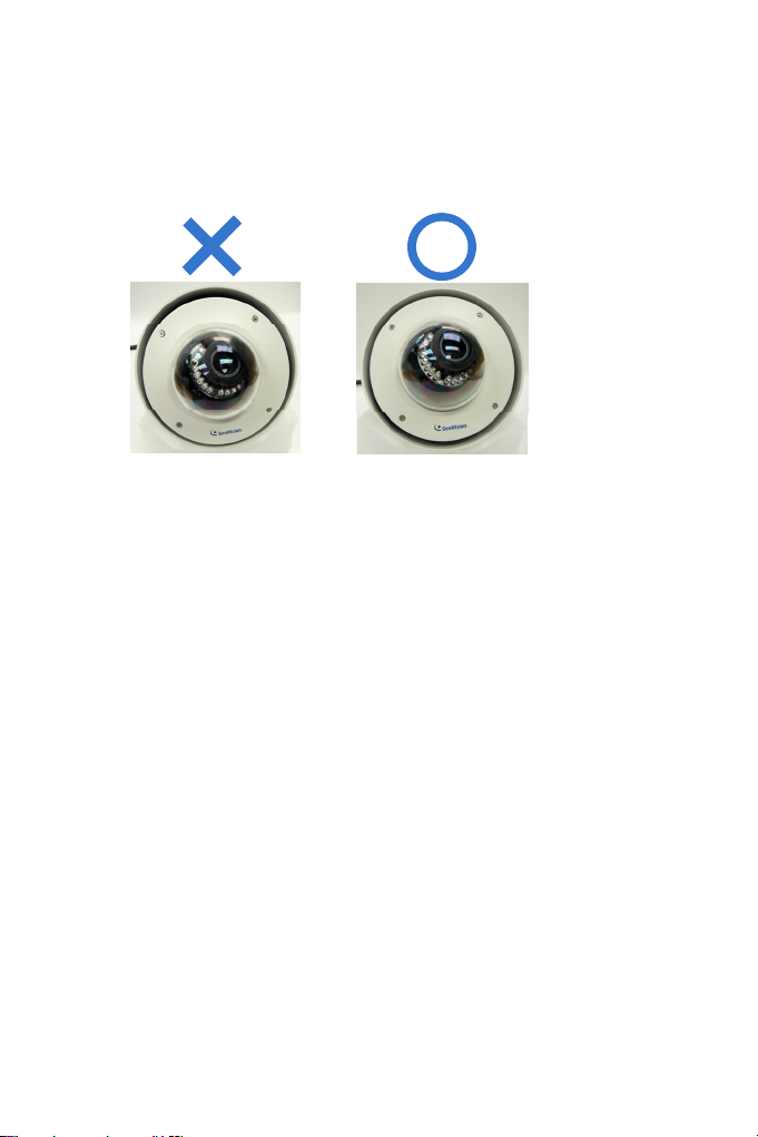
Note for Closing the Bullet Camera Cover
To ensure that the camera performs its full capacity against water and
dust, adhere to the following guidelines when closing the Bullet Camera
cover:
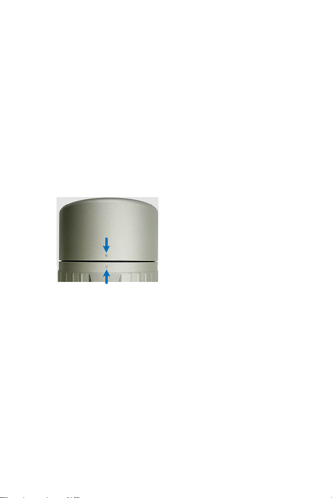
1. Line up the dots
Tighten the camera cover until the dots on the cover and the body
line up as indicated below.
2. Make your own marks
For earlier models, you may not have dots on your camera. In this
case, make your own marks on the camera cover and the body to
note down the position.
XXV
Page 28

XXVI
Page 29

Chapter 1 Introduction
The GV-IPCAM H.264 series offers a comprehensive range of IP cameras
supporting your needs for IP surveillance in various environmental
conditions. For detailed features of each model, refer to the corresponding
chapter.
Model Model No. Description
1.3 MP Low Lux,
H.264, D/N, Auto Iris,
f: 2.8 ~ 12 mm, F/1.4,
1/3’’ CS Lens
1.3 MP, H.264 D/N,
Auto Iris, f: 2.8 ~ 12
mm, F/1.4, 1/3’’ CS
Lens
1.3 MP, H.264 D/N,
Fixed Iris, f: 4 mm,
F/1.5, 1/3’’ CS Lens
1 MP, H.264 D/N WDR
Pro, Fixed Iris, f: 2.8 ~
12 mm, F/1.4, 1/3’’ CS
Lens
2 MP, H.264 D/N, Auto
Iris, f: 2.8 ~ 6 mm,
F/1.3, 1/3’’ CS Lens
2 MP, H.264 D/N, Auto
Iris, f: 2.8 ~ 12 mm,
F/1.4, 1/3’’ CS Lens
3 MP, H.264 D/N,
Auto Iris, f: 3.1 ~ 8 mm,
F/1.2, 1/3’’ CS Lens
Box Camera
GV-BX120D
GV-BX130D-0
GV-BX130D-1
GV-BX140DW
GV-BX220D-2
GV-BX220D-3
GV-BX320D-0
Varifocal
Lens
Varifocal
Lens
Fixed
Lens
Varifocal
Lens
Page 30
Model Model No. Description
3 MP, H.264 D/N,
Box Camera
GV-BX320D-1
GV-BX520D
GV-BX1200-0F
GV-BX1300-0F
GV-BX2400-0F
GV-BX3400-0F
GV-BX1200-1F
GV-BX1200-2F
GV-BX1300-1F
GV-BX1300-2F
GV-BX2400-1F
GV-BX2400-2F
GV-BX3400-1F
GV-BX3400-2F
GV-BX1200-3V
Varifocal
Lens
Fixed
Lens
Varifocal
Lens
Auto Iris, f: 2.8 ~ 6 mm,
F/1.3, 1/3’’ CS Lens
5 MP, H.264 D/N,
Manual Iris,
f: 4.5 ~ 10 mm, F/1.6,
1/2’’ CS Lens
1.3 MP Low Lux,
H.264, D/N, Fixed Iris,
f: 4 mm, F/1.5,
1/3’’ CS Lens
1.3 MP, H.264, D/N,
Fixed Iris, f: 4 mm,
F/1.5, 1/3’’ CS Lens
2 / 3 MP, H.264, D/N,
WDR Pro, Fixed Iris,
f: 4 mm, F/1.5, 1/3’’ CS
Lens
1.3 MP Low Lux,
H.264, D/N, Fixed Iris,
f: 8 / 12 mm, F/1.6,
1/2.5’’ CS Lens
1.3 MP, H.264, D/N,
Fixed Iris, f: 8 / 12 mm,
F/1.6, 1/2.5’’ CS Lens
2 / 3 MP, H.264, D/N,
WDR Pro, Fixed Iris,
f: 8 / 12 mm, F/1.6,
1/2.5’’ CS Lens
1.3 MP Low Lux, H.264
D/N, Auto Iris, f: 2.8 ~
12 mm, F/1.4, 1/3’’ CS
Lens
2
Page 31

1
Model Model No. Description
1.3 MP, H.264 D/N,
Auto Iris, f: 2.8 ~ 12
mm, F/1.4,
1/3’’ CS Lens
2 MP, H.264 D/N, WDR
Pro, Auto Iris,
f: 2.8 ~ 12 mm, F/1.4,
1/3’’ CS Lens
2 MP / 3 MP, H.264
D/N, WDR Pro, Auto
Iris, f: 3 ~ 10.5 mm,
F/1.4, 1/2.7’’ CS Lens
3 MP, H.264 D/ N,
WDR Pro, Auto Iris,
f: 2.8 ~ 6 mm, F/1.3,
1/3’’ CS Lens
5 MP, H.264 D/N,
Manual Iris, f: 4.5 ~ 10
mm, F/1.6,
1/2’’ CS Lens
1.3 MP, H.264, D/N,
Fixed Iris,
f: 3 / 4 / 8 mm, F/1.6,
1/3’’ M12 Lens
2 MP, H.264, D/N,
Fixed Iris,
f: 3 / 4 / / 8 mm, F/1.6,
1/3’’ M12 Lens
3 MP, H.264, D/N,
Fixed Iris,
f: 3 / 4 / / 8 mm, F/1.6,
1/3’’ M12 Lens
1.3 / 2 / 3 MP, H.264,
D/N, Fixed Iris,
f: 2.1 mm, F/1.8, 1/3’’
M12 Lens
Box Camera
Ultra Box
Camera
GV-BX1300-3V
GV-BX2400-3V
GV-BX2400-4V
GV-BX3400-4V
GV-BX3400-5V
GV-BX5300
GV-UBX1301-0F
GV-UBX1301-1F
GV-UBX1301-2F
GV-UBX2301-0F
GV-UBX2301-1F
GV-UBX2301-2F
GV-UBX3301-0F
GV-UBX3301-1F
GV-UBX3301-2F
GV-UBX1301-3F
GV-UBX2301-3F
GV-UBX3301-3F
(Coming)
Varifocal
Lens
Fixed
Lens
Introduction
3
Page 32

Model Model No. Description
1.3 MP Low Lux,
H.264, D/N, Auto Iris,
f: 2.8 ~ 12 mm, F/1.4,
1/3’’ CS Lens
2 MP, H.264 D/N, Auto
Iris, f: 2.8 ~ 6 mm,
F/1.3, 1/3’’ CS Lens
3 MP, H.264 D/N,
Auto Iris, f: 2.8 ~ 6 mm,
F/1.3, 1/3’’ CS Lens
5 MP, H.264 D/N,
Manual Iris, f: 4.5 ~ 10
mm, F/1.6, 1/2’’ CS
Lens
1.3 MP Super Low Lux,
H.264, D/N, Auto Iris, f:
3 ~ 10.5 mm, F/1.4,
1/2.7’’ CS Lens
2 MP / 3 MP, H.264,
D/N, WDR Pro, Auto
Iris, f: 3 ~ 10.5 mm,
F/1.4, 1/2.7’’ CS Lens
5 MP, H.264, D/N,
Manual Iris, f: 4.5 ~ 10
mm, F/1.6, 1/2’’ CS
Lens
IR Arctic Box
Camera
GV-BX120D-E
GV-BX220D-E
GV-BX320D-E
GV-BX520D-E
GV-BX1500-E
(Coming)
GV-BX2400-E
GV-BX3400-E
GV-BX5300-E
Varifocal
Lens
4
Page 33

1
Model Model No. Description
1.3 MP Low Lux,
H.264, Color, Fixed
Iris, f: 4.05 mm, F/1.5,
1/3’’ M12 Mount
2 MP / 3 MP / 5 MP,
H.264, Color, Fixed
Iris, f: 2.54 mm, F/2.8,
1/2.5’’ M12 Mount
1.3 MP Low Lux,
H.264, Color, Fixed
Iris, f: 4.05 mm, F/1.5,
1/3’’ M12 Mount
2 MP / 3 MP / 5 MP,
H.264, Color, Fixed
Iris, f: 2.54 mm, F/2.8,
1/2.5’’ M12 Mount
2 MP / 3 MP H.264,
Color, WDR Pro, Fixed
Iris, f: 4 mm, F/1.5,
1/3’’, M12 Lens
2 MP / 3 MP H.264,
Color, WDR Pro, Fixed
Iris, f: 8 / 12 mm, F/1.6,
1/3’’, M12 Lens
1.3 MP Low Lux,
H.264, D/N, Auto Iris,
3x Optical Zoom,
f: 3 ~ 9 mm, F/1.2,
1/2.7’’ ø 14 Lens
Mini Fixed
Dome
Mini Fixed
Rugged
Dome
Ultra Bullet
Camera
GV-MFD120
GV-MFD130
GV-MFD220
GV-MFD320
GV-MFD520
GV-MDR120
GV-MDR220
GV-MDR320
GV-MDR520
GV-MDR2400-0F
GV-MDR3400-0F
(Coming)
GV-MDR2400-1F
GV-MDR2400-2F
GV-MDR3400-1F
GV-MDR3400-2F
(Coming)
GV-UBL1211
Fixed
Lens
Fixed
Lens
Motorized
varifocal
Lens
Introduction
5
Page 34

Model Model No. Description
2 MP / 3 MP, H.264,
D/N, Low Lux, WDR
Pro, Auto Iris, 3x
Optical Zoom, f: 3 ~ 9
mm, F/1.2, 1/2.7’’ ø 14
Lens
1.3 MP, H.264, D/N,
Fixed Iris, f: 3 / 4 / 8 /
12 mm, F/1.6, 1/3’’
M12 Lens
1.3 MP, H.264, D/N,
Fixed Iris, f: 2.1 mm,
F/1.8, 1/3’’ M12 Lens
2 MP / 3 MP, H.264,
D/N, WDR Pro, Fixed
Iris, f: 3 / 4 / 8 / 12 mm,
F/1.6, 1/3’’ M12 Lens
2 MP / 3 MP, H.264,
D/N, WDR Pro, Fixed
Iris, f: 2.1 mm, F/1.8,
1/3’’ M12 Lens
1.3 MP / 2 MP, H.264,
Fixed Iris, f: 3.35 mm,
F/2.4, 1/3’’ M12 Lens
Wireless, Fixed Iris,
f: 3.35 mm, F/2.4, 1/3’’
M12 Lens
Ultra Bullet
Camera
Cube
Camera
GV-UBL2411
GV-UBL3411
GV-UBL1301-0F
GV-UBL1301-1F
GV-UBL1301-2F
GV-UBL1301-3F
GV-UBL1301-4F
GV-UBL2401-0F
GV-UBL2401-1F
GV-UBL2401-2F
GV-UBL2401-3F
GV-UBL3401-0F
GV-UBL3401-1F
GV-UBL3401-2F
GV-UBL3401-3F
GV-UBL2401-4F
GV-UBL3401-4F
GV-CB120
GV-CB220
GV-CBW120
GV-CBW220
Motorized
varifocal
Lens
Fixed
Lens
Fixed
Lens 1.3 MP / 2 MP, H.264,
6
Page 35

1
Introduction
Model Model No. Description
1.3 MP / 2 MP, H.264,
Fixed Iris, f: 3.35 mm,
F/2.4, 1/3’’ M12 Lens
1.3 MP / 2 MP, H.264,
Wireless, Fixed Iris,
f: 3.35 mm, F/2.4, 1/3’’
M12 Lens
1.3 MP Low Lux,
H.264, D/N, Auto Iris,
f: 3 ~ 9 mm, F/1.2,
1/2.7’’, ø 14 mm
1.3 MP / 2 MP / 3 MP,
H.264, D/N, Auto Iris,
f: 3 ~ 9 mm, F/1.2,
1/2.7’’, ø 14 mm
2 MP / 3 MP H.264,
D/N, WDR Pro, Auto
Iris, f: 3 ~ 9 mm, F/1.2,
1/2.7’’, ø 14 mm
1.3 MP low lux / 2 MP
/ 3 MP, H.264, D/N,
Auto Iris, 3x Optical
Zoom, f: 3 ~ 9 mm,
F/1.2, 1/2.7’’, ø 14 mm
5 MP H.264, D/N, Auto
Iris, 2X Optical Zoom,
f: 4.5 ~ 9 mm, F/1.2,
1/2.7’’, ø 14 mm
10x Optical Zoom, D1,
H.264, D/N, Fixed Iris
1.3 MP / 2 MP / 3 MP,
H.264, D/N, Fixed Iris.
f: 4 mm, F/1.5, 1/2.5’’
M12 Lens
Advanced
Cube
Camera
Bullet
Camera
PTZ
Camera
PT Camera
GV-CA120
GV-CA220
GV-CAW120
GV-CAW220
GV-BL120D
GV-BL1200
GV-BL130D
GV-BL1300
GV-BL220D
GV-BL320D
GV-BL2400
GV-BL3400
GV-BL1210
GV-BL2410
GV-BL3410
GV-BL5310
GV-PTZ010D
GV-PT130D
GV-PT220D
GV-PT320D
Fixed
Lens
Varifocal
Lens
Motorized
varifocal
Lens
NTSC
PAL
Fixed
Lens
7
Page 36

Model Model No. Description
GV-VD120D
1.3 MP, H.264, D/N,
Low Lux, Auto Iris
2 MP, H.264, D/N,
D/N, Auto Iris
3 MP, H.264, D/N,
Auto Iris
2 / 3 MP, H.264, D/N,
WDR Pro, Auto Iris
Vandal
Proof IP
Dome
(IK10+, Transparent Cover)
GV-VD121D
(IK10+, Smoked Cover)
GV-VD122D
(IK7, Transparent Cover)
GV-VD123D
(IK7, Smoked Cover)
GV-VD220D
(IK10+, Transparent Cover)
GV-VD221D
(IK10+, Smoked Cover)
GV-VD222D
(IK7, Transparent Cover)
GV-VD223D
(IK7, Smoked Cover)
GV-VD320D
(IK10+, Transparent Cover)
GV-VD321D
(IK10+, Smoked Cover)
GV-VD322D
(IK7, Transparent Cover)
GV-VD323D
(IK7, Smoked Cover)
GV-VD2400 (Coming)
(IK10+, Transparent Cover)
GV-VD3400 (Coming)
(IK10+, Transparent Cover)
Varifocal
Lens
8
Page 37

1
Introduction
Model Model No. Description
1.3 MP Low Lux / 2
MP / 3 MP, H.264,
D/N, Low Lux, Auto
Iris, f: 3 ~ 9 mm, F/1.3,
1/3’’ ø 14 mm Mount
1.3 MP Low Lux,
H.264, D/N, Auto Iris,
f: 3 ~ 9 mm, F/1.2,
1/2.7’’ ø 14 mm Mount
2 MP / 3 MP, H.264,
D/N, WDR Pro, Auto
Iris, f: 3 ~ 9 mm, F/1.2,
1/2.7’’ ø 14 mm Mount
5 MP, H.264, D/N,
Auto Iris, f: 4.5 ~ 10
mm, F/1.6, 1/2.5’’ CS
Mount
1.3 MP Low Lux,
H.264, D/N, Auto Iris, ,
3x Optical Zoom, f: 3
~ 9 mm, F/1.2, 1/2.7’’
ø 14 mm Mount
2 MP / 3 MP, H.264,
D/N, WDR Pro, Auto
Iris, 3x Optical Zoom,
f: 3 ~ 9 mm, F/1.2,
1/2.7’’ ø 14 mm Mount
Fixed IP
Dome
GV-FD120D
GV-FD220D
GV-FD320D
GV-FD1200
GV-FD2400
GV-FD3400
GV-FD5300
GV-FD1210
GV-FD2410
GV-FD3410
Varifocal
Lens
Motorized
Varifocal
Lens
9
Page 38

1.1 System Requirement
To perform the GV-IPCAM H.264 operations through Web browser, ensure
your PC is in good network connection, and use one of the following web
browsers:
• Microsoft Internet Explorer 7.x or later
• Google Chrome
• Mozilla Firefox
• Safari
Note:
1 For the users of Internet Explorer 8, additional settings are
required. For details, see Appendix A.
2 With non-IE browsers,
A. Motion Detection, Tampering Alarm, Visual Automation, Text
Overlay, two-way audio and GPS map settings are not
supported.
B. only the Play function is available on the live view window
(Figure 15-3)
C. RTSP streaming must be kept as enabled. For more detail,
see 16.3.8 RTSP.
10
Page 39

Chapter 2 Box Camera
The Box Camera is a series of indoor IP cameras containing fixed focal
and varifocal models in different resolutions. The Box camera allows lens
replacement and features an automatic infrared-cut filter for day and night
surveillance. The GV-BX1200 Series / 2400 Series / 3400 Series / 5300
can be also connected wirelessly using a GV-WiFi Adapter (optional).
Several models (GV-The GV-BX2400 Series / 3400 Series) are equipped
with WDR Pro to produce clear image for scenes with contrasting intensity
of lights (see 2.2.1 Wide Dynamic Range Pro for details). The Box Camera
models are detailed below:
Box Camera
Model No. Specifications Description
GV-BX120D
GV-BX130D-0
Varifocal
Lens
Megapixel, Auto Iris,
f:2.8 ~ 12 mm, F/1.4,
1/3” CS Lens
Megapixel, Auto Iris,
f: 2.8 ~ 12 mm, F/1.4,
1/3’’ CS Lens
1.3 MP, H.264,
Low Lux, D/N
1.3 MP, H.264,
D/N
GV-BX130D-1 Fixed Lens
GV-BX140DW
Varifocal
Lens
Megapixel, Fixed Iris,
f: 4 mm, F/1.4,
1/3’’ CS Lens
Megapixel, Fixed Iris,
f: 2.8 ~ 12 mm, F/1.4,
1/3’’ CS Lens
1.3 MP, H.264,
D/N
1 MP, H.264,
D/N, WDR Pro
Page 40

Model No. Specifications Description
GV-BX220D-2
GV-BX220D-3
GV-BX320D-0
GV-BX320D-1
GV-BX520D
GV-BX1200-0F
GV-BX1300-0F
GV-BX2400-0F
GV-BX3400-0F
GV-BX1200-1F
GV-BX1300-1F
GV-BX2400-1F
GV-BX3400-1F
Varifocal
Lens
Fixed Lens
Megapixel, Auto Iris,
f: 2.8 ~ 6 mm,
F/1.3, 1/3’’ CS Lens
Megapixel, Auto Iris,
f: 2.8 ~ 12 mm,
F/1.4, 1/3’’ CS Lens
Megapixel, Auto Iris,
f:3.1 ~ 8 mm, F/1.2,
1/3” CS Lens
Megapixel, Auto Iris,
f: 2.8 ~ 6 mm, F/1.3,
1/3’’ CS Lens
Megapixel, Manual
Iris, f: 4.5 ~ 10 mm,
F/1.6, 1/2’’ CS Lens
Megapixel, Fixed Iris,
f: 4 mm, F/1.5, 1/3’’
CS Lens
Megapixel, Fixed Iris,
f: 8 mm, F/1.6, 1/2.5’’
CS Lens
2 MP, H.264,
D/N
MP, H.264,
D/N
3 MP, H.264,
D/N
5 MP, H.264,
D/N
1.3 MP, H.264,
Low Lux, D/N
1.3 MP, H.264,
D/N
2 MP, H.264,
D/N, WDR Pro
3 MP, H.264,
D/N, WDR Pro
1.3 MP, H.264,
Low Lux, D/N
1.3 MP, H.264,
D/N
2 MP, H.264,
D/N, WDR Pro
3 MP, H.264,
D/N, WDR Pro
12
Page 41

Box Camera
2
Model No. Specifications Description
GV-BX1200-2F
GV-BX1300-2F
GV-BX2400-2F
GV-BX3400-2F
GV-BX1200-3V
GV-BX1300-3V
GV-BX2400-3V
GV-BX2400-4V
GV-BX3400-4V
GV-BX3400-5V
GV-BX5300
Fixed Lens
Varifocal
Lens
Megapixel, Fixed Iris,
f: 12 mm, F/1.6,
1/2.5’’ CS Lens
Megapixel, Auto Iris,
f:2.8 ~ 12 mm, F/1.4,
1/3” CS Lens
Megapixel, Auto Iris,
f:3 ~ 10.5 mm, F/1.4,
1/2.7” CS Lens
Megapixel, Auto Iris,
f: 2.8 ~ 6 mm, F/1.3,
1/3’’ CS Lens
Megapixel, Manual
Iris, f: 4.5 ~ 10 mm,
F/1.6, 1/2’’ CS Lens
1.3 MP, H.264,
Low Lux, D/N
1.3 MP, H.264,
D/N
2 MP, H.264,
D/N, WDR Pro
3 MP, H.264,
D/N, WDR Pro
1.3 MP, H.264,
Low Lux, D/N
1.3 MP, H.264,
D/N
2 MP, H.264,
D/N, WDR Pro
3 MP, H.264,
D/N, WDR Pro
5 MP, H.264,
D/N
13
Page 42

2.1 Packing List
Box Camera
Terminal Block
Fixed Focal or Varifocal Megapixel Lens
Six Lens Rings
One 0.125 mm Lens Ring (for GV-BX140DW only)
Video Out Wire
Camera Holder
GV-IPCAM H.264 Software CD
GV-IPCAM H.264 Quick Start Guide
GV-NVR Software DVD
GV-NVR Quick Start Guide
Note: Power adapter can be purchased upon request.
14
Page 43

2.2 Features
Image sensor
Camera Model Frame Rate
GV-BX120D
GV-BX1200 Series
GV-BX130D Series
GV-BX1300 Series
GV-BX220D Series
GV-BX320D Series
GV-BX520D
GV-BX5300
GV-BX140DW 1/3’’ progressive scan CMOS
GV-BX2400 Series
GV-BX3400 Series
Dual streams from H.264 or MJPEG
Frame rate:
Camera Model Frame Rate
GV-BX120D
GV-BX130D Series
GV-BX1200 Series
GV-BX1300 Series
GV-BX140DW Up to 30 fps at 1280 x 720
GV-BX220D Series
GV-BX2400 Series
GV-BX320D Series
GV-BX3400 Series
GV-BX520D
GV-BX5300
1/3’’ progressive scan low lux
CMOS
1/2.5’’ progressive scan CMOS
1/3.2’’ progressive scan CMOS
Up to 30 fps at 1280 x 1024
Up to 30 fps at 1920 x 1080
Up to 20 fps at 2048 x 1536
Up to 10 fps at 2560 x 1920
Box Camera
2
15
Page 44

Day / Night function (with removable IR-cut filter)
Wide Dynamic Range Pro
(GV-BX140DW / 2400 Series / 3400 Series only
Defog
Two-way audio
One sensor input and alarm output
TV-out support
Micro SD memory card slot (SDHC / SDXC for class 6 or above)
Mini USB slot for WiFi Adapter or a USB hard drive (for GV-BX1200
Series / 1300 Series / 2400 Series / 3400 Series / 5300 only)
Motion detection
Tampering alarm
Visual automation
Privacy mask
Text overlay
IP address filtering
Power supply: DC 12V and PoE
Megapixel lens
Support for iPhone, iPad, Android and 3GPP
31 languages on Web interface
ONVIF (Profile S) conformant
)
16
Page 45

Box Camera
2
2.2.1 Wide Dynamic Range Pro
Objects may appear as silhouettes when they are backed with intense
lights. The Wide Dynamic Range Pro (WDR Pro) is designed to solve this
problem using a WDR sensor. In GV-BX140DW, GV-BX2400 Series and
GV-BX3400 Series, the WDR sensor is able to process the image and
show details in bright and dark areas at the same time. An example of
WDR Pro in action is shown below.
No WDR: underexposure
WDR: perfect exposure
For GV-IPCam H.264 models that support WDR, the WDR effect is
achieved through software programming.
17
Page 46

2.3 Overview
2.3.1 GV-BX120D / 130D Series / 140DW / 220D Series / 320D Series / 520D
2 3 4 5 6
1
13
12
11
14
15
7 8 9
10
Figure 2-1
Note:
1. The Light Sensor (No.11) is only available in GV-BX140DW. Keep
the Light Sensor unobscured for accurate light detection.
2. The Iris Screw (No.13) is only available for GV-BX520D.
3. The Zoom Screw (No. 15) is not available for GV-BX130D-1.
No. Name Description
Connects to a portable monitor for setting
1 Video Out
2 Memory Card Slot
3 Audio Out Connects a speaker for audio output.
4 Audio In Connects a microphone for audio input.
5 I/O Terminal Block For details, see 2.6 I/O Terminal Block.
18
the focus and angle of Box Camera during
initial installation.
Inserts a micro SD card (SDHC / SDXC for
class 6 or above) to store recording data.
16
Page 47

Box Camera
2
No. Name Description
6 Power LED
7 Auto Iris
Connector
8 DC 12V Port Connects to power.
9 LAN / PoE Connects to a 10/100 Ethernet or PoE.
10 Default Resets all configurations of the GV-IPCAM
11 Light Sensor Detects light to switch between day and night
12 Focus Screw Adjusts the focus of the camera.
13 Iris Screw Adjusts the iris of the camera.
14 Microphone Records the sounds.
15 Zoom Screw Adjusts the zoom of the camera.
16 Status LED Turns on when the unit is ready for use. For
LED Description
Power LED turns green The system powers on and succeeds to boot
Status LED turns green The system is ready for use.
Indicates the power is supplied. For detail, see
the table below.
Plug the iris control cable to the connector.
Note that Auto Iris Connector is not functional
in GV-BX130D-1, GV-BX140DW and GV-
BX520D.
H.264 to the default factory settings. See 18.3
Restoring to Factory Default Settings.
mode.
detail, see the table below.
up.
19
Page 48

2.3.2 GV-BX1200 Series / 1300 Series / 2400 Series / 3400 Series / 5300
5
1 2 4
6 7
8 9
10311
12 13
Figure 2-2
14
Note:
1. GV-BX1200-0F ~ 2F, GV-BX1300-0F ~ 2F, GV-BX2400-0F ~ 2F
and GV-BX3400-0F ~ 2F) do not have a Zoom Screw (No. 13).
2. The Iris Screw (No. 12) is only available in GV-BX5300.
No. Name Description
Connects to a portable monitor for setting the
1 Video Out
Memory Card
2
Slot
3 Mini USB Slot
4 Audio Out Connects a speaker for audio output.
5 Audio In Connects a microphone for audio input.
focus and angle of Box Camera during initial
installation.
Inserts a micro SD card (SDHC / SDXC for
class 6 or above) to store recording data.
Connects to a GV-WiFi Adapter or a USB
hard drive.
15
16
20
Page 49

Box Camera
2
No. Name Description
I/O Terminal
6
Block
7 Power LED
Auto Iris
8
Connector
9 DC 12V Port Connects to power.
10 LAN / PoE Connects to a 10/100 Ethernet or PoE.
11 Default
12 Iris Screw Adjusts the iris of the camera.
13 Zoom Screw Adjusts the zoom of the camera.
14 Microphone Records the sounds.
15 Focus Screw Adjusts the focus of the camera.
16 Status LED
LED Description
Power LED turns green The system powers on and succeeds to boot
Status LED turns green The system is ready for use.
Connects to I/O devices. For details, see 2.6
I/O Terminal Block.
Indicates the power is supplied. For detail,
see the table below.
Plug the iris control cable to the connector.
Note that Auto Iris Connector is not functional
in GV-BX1200-0F ~ 2F, GV-BX1300-0F ~ 2F,
GV-BX2400-0F ~ 2F and GV-BX3400-0F ~
2F.
Resets all configurations of the GV-IPCAM
H.264 to the default factory settings. See 18.3
Restoring to Factory Default Settings.
Turns on when the unit is ready for use. For
detail, see the table below.
up.
21
Page 50

2.4 Connecting the Camera
The Box Camera is designed for indoor use. Please make sure the
installing site is shielded from rain and moisture.
2.4.1 GV-BX120D / 130D Series / 140DW / 220D Series / 320D Series / 520D
Figure 2-3
1. If you are using the auto iris model, plug the iris control cable to the
Auto Iris Connector on the camera.
2. Use a standard network cable to connect the camera to your network.
3. Optionally connect a speaker and an external microphone.
4. Optionally connect a monitor using a Video Out wire. Enable this
function by selecting your signal format at the
Web interface. See 14.1.1 Video Settings.
5. Optionally connect to input / output devices or an infrared illuminator.
For details, see 2.5.2 Infrared Illuminator and 2.6 I/O Terminal Block.
TV Out field on the
22
Page 51

Box Camera
2
6. Connect power using one of the following methods:
plugging the supplied power adapter to the power port.
using the Power over Ethernet (PoE) function and the power will
be provided over the network cable.
7. The status LED of the camera will be on.
8. You are ready to access the live view, adjust the image clarity and
configure the basics. See Getting Started, Chapter 12.
23
Page 52

2.4.2 GV-BX1200 Series / 1300 Series / 2400 Series / 3400 Series / 5300
Figure 2-4
1. If you are using the auto iris model, plug the iris control cable to the
Auto Iris Connector on the camera.
2. Connect to network using one of the following methods:
Wired Connection: Use a standard network cable to connect the
camera to your network and optionally connect a USB hard drive
to the mini USB port.
Wireless Connection: Connect a GV-WiFi Adapter (optional
accessory).
3. Optionally connect a speaker and an external microphone.
4. Optionally connect a monitor using a Video Out wire. Enable this
function by selecting your signal format at the TV Out field on the Web
interface. See 14.1.1 Video Settings.
5. Optionally connect to input / output devices or an infrared illuminator.
For details, see 2.5.2 Infrared Illuminator and 2.6 I/O Terminal Block.
24
Page 53

Box Camera
2
6. Connect power using one of the following methods:
plugging the supplied power adapter to the power port.
using the Power over Ethernet (PoE) function and the power will
be provided over the network cable.
7. The status LED of the camera will be on.
8. You are ready to access the live view, adjust the image clarity and
configure the basics. See Getting Started, Chapter 12.
Note:
1. Mind the following limitations and requirements for the mini USB
port:
The USB hard drive must be of 2.5’’ or 3.5’’, version 2.0 or
above
The USB hard drive’s storage capacity must not exceed 2TB
USB flash drives and USB hubs are not supported
External power supply is required for the USB hard drive
2. To connect a GV-WiFi Adapter, make sure it is connected before
the camera is powered on.
25
Page 54

2.5 Accessory Installation
2.5.1 C-Mount Lenses
If you use a C-mount lens, it requires a certain distance from the camera’s
imaging chip to focus the lens. Mount the supplied C-mount lens adapter /
lens ring to the camera, and then secure the lens onto the camera body.
Three types of C-mount lens rings are provided for Box Camera:
0.188 mm (transparent color) x 2
0.125 mm (black color with a glossy surface) x 2
0.254 mm (black color with a matt surface) x 2
For GV-BX140DW, a 0.125 mm is provided.
Note: The C-mount lens rings are specially designed for Box Camera.
Besides the supplied C-mount lens rings, each of these models has
already included with the necessary lens ring.
26
Figure 2-5
Page 55

Box Camera
2
2.5.2 Infrared Illuminators (Optional)
If you use an infrared (IR) illuminator with I/O function, follow the steps
below to install it.
1. Connect the infrared illuminator to the terminal block on the camera.
See 2.6 The I/O Terminal Block.
2. Access the Web interface of the camera.
3. Select
4. Click
For the
settings, see 14.1.1 Video Settings.
Video and Motion, select Video Settings, select Streaming 1
and set the
Trigger IR by D/N.
Trigger by Input or Trigger IR by D/N function and D/N sensitivity
IR Check Function option to be Trigger by Input or
Apply.
27
Page 56

2.6 I/O Terminal Block
The terminal block, located on the back panel of the Box Camera, provides
the interface to one input and one output devices. The I/O terminal block
can be used for applications such as motion detection, event alerts via E-
Mail and FTP, and center monitoring through Center V2 and VSM.
2.6.1 Pin Assignment
The pin assignment for the I/O terminal block:
For the output point, please check if your output device meets the following
Absolute Maximum Ratings before connecting it to the output point.
Breakdown Voltage 277V AC, 30V DC
Continuous Load Current 5A (NO), 3A (NC)
Note: Absolute Maximum Ratings are those values beyond which
damage to the camera may occur. Continuous operation of the camera at
the absolute rating level may affect the camera reliability.
The Box Camera support one digital input and one digital output of dry
contact.
I/O
123
Figure 2-6
Pin Function
1 Digital Input
2 GND
3 Digital Output
For details on how to enable an installed I/O device, see 14.2 I/O Settings.
28
Page 57

Box Camera
2
2.6.2 Connecting to GV-Relay V2 (Optional)
The Box Camera can only drive a maximum load of 200mA 5V DC.
Connect the camera to a GV-Relay V2 module (optional product) to
expand the maximum voltage load to 10A 250V AC, 10A 125V AC or 5A
100V DC.
To connect the Box Camera to GV-Relay V2, refer to the figure and table
below.
Output Device
123
Connect to Power
Figure 2-7
GV-Relay V2 I/O Terminal Block
COM Pin 2 (GND)
DO1 Pin 3 (Digital Output)
I/O
29
Page 58

Chapter 3 Ultra Box Camera
The Ultra Box Camera is a series of light-weighted cameras designed for
indoor usage. Equipped with IR-cut filter and built-in IR LEDs, the Ultra Box
Camera provides excellent image quality. The camera supports PoE and
can be installed intuitively. Nine models of varying resolutions and focal
lengths are available.
Model No. Specifications Description
GV-UBX1301-0F
GV-UBX1301-1F
GV-UBX1301-2F
GV-UBX2301-0F
GV-UBX2301-1F
GV-UBX2301-2F
GV-UBX3301-0F
GV-UBX3301-1F
GV-UBX3301-2F
GV-UBX1301-3F
GV-UBX2301-3F
GV-UBX3301-3F
(Coming)
Fixed Lens
Megapixel, Fixed
Iris, f: 3 / 4 / 8 mm,
F/1.6, 1/3’’ M12 mm
Lens Mount
Megapixel, Fixed
Iris, f: 2.1 mm,
F/1.8, 1/3’’ M12 mm
Lens Mount
1.3 MP, H.264,
D/N
2 MP, H.264,
D/N
3 MP, H.264,
D/N
1.3 / 2 / 3 MP,
H.264, D/N
Page 59

3.1 Packing List
• Ultra Box Camera
• Supporting rack x 1
• Screw x 3
• Screw anchor x 3
• GV-IPCAM H.264 Software CD
• GV-IPCAM H.264 Quick Start Guide
• GV-NVR Software DVD
• GV-NVR Quick Start Guide
Note: Power adapter can be purchased upon request.
Ultra Box Camera
3
31
Page 60

3.2 Features
• 1/2.5’’ progressive scan CMOS
• Dual streams from H.264 or MJPEG
• Frame rate
Camera Model Frame Rate
GV-UBX1301 Series Up to 30 fps at 1280 x 1024
GV-UBX2301 Series Up to 30 fps at 1920 x 1080
GV-UBX3301 Series Up to 20 fps at 2048 x 1536
• Intelligent IR
• Day and night function (with removable IR-cut filter)
• Wide Dynamic Range (WDR)
• Defog
• Micro SD memory card slot (SDHC / SDXC for class 6 or above)
• Two-way audio
• Motion detection
• Tampering alarm
• Text overlay
• Privacy mask
• IP address filtering
• DC 5V / PoE
• Megapixel lens
• Support for iPhone, iPad, Android and 3GPP
• 31 languages on Web interface
• ONVIF (Profile S) conformant
32
Page 61

3.3 Overview
Ultra Box Camera
3
4
1
5
2
6
3
Figure 3-1
No. Name Description
1 Audio Out Connects a speaker for audio output.
Resets the camera to factory defaults.
2 Default
3 LAN / PoE Connects to a 10/100 Ethernet or PoE.
4 Microphone Records sounds.
5 Memory Card Slot
6 DC 5V Terminal Block Connects to power.
LED Indicator Description
Status LED
Power LED
The status LED turns on (green) when the system
is ready for use.
The power LED turns on (green) when power is
supplied to the camera.
See 18.3 Restoring to Factory Default
Settings.
Inserts a micro SD card (for SDHC /
SDXC for class 6 or above) to store
recording data.
33
Page 62

3.4 Installation
You can stand the Ultra Box Camera on a plain surface or install it to wall
and ceiling. Follow the steps below to install, connect and adjust your Ultra
Box Camera.
1. To install the device on the wall/ceiling, put the supporting rack on the
desired location and make marks for screw anchors.
Figure 3-2
2. Drill the marks and insert the screw anchors.
3. Secure the supporting rack onto the wall/ceiling using the supplied
screws.
4. Secure the camera onto the supporting rack and fasten the indicated
screw.
34
Figure 3-3
Page 63

Ultra Box Camera
3
5. Connect the network and power cables to the camera. See 3.5
Connecting the Camera.
6. Access the live view. See 14.1 Accessing the Live View.
7. Adjust the angle of the camera based on live view and fasten the
indicated screw.
Figure 3-4
35
Page 64

3.5 Connecting the Camera
3
1
2
Figure 3-4
1. Connect power using one of the following methods:
• Plug the power adapter to the 5V terminal block. The power
adapter is an optional device. For detail, see Options in the
manual.
• Use the Power over Ethernet (PoE) function and the power will be
provided over the network cable.
The power and status LEDs shall turn on (green).
2. Use a standard network cable to connect the camera to your network.
3. Optionally connect a speaker.
4. Insert a micro SD card (SDHC / SDXC for class 6 or above).
5. You are ready to access the live view, adjust the image clarity and
configure the basics. See Getting Started, Chapter 14.
36
Page 65

Chapter 4 IR Arctic Box Camera
The IR Arctic Box Camera is a series of outdoor cameras designed for
environments of extreme temperatures. The cameras adhere to IP67 and
IK10 protection standards, and are equipped with IR LEDs and removable
IR-cut filter for day and night surveillance. The GV-BX2400-E / 3400-E are
equipped with WDR Pro to produce clear image for scenes containing
contrasting intensity of lights (see 2.2.1 Wide Dynamic Range Pro for
details).
IR Arctic Box Camera
Model No. Specifications Description
GV-BX120D-E
GV-BX220D-E
GV-BX320D-E
GV-BX520D-E
GV-BX1500-E
(Coming)
GV-BX2400-E
GV-BX3400-E
GV-BX5300-E
Varifocal
Lens
Auto Iris, f: 2.8 ~ 12
mm, F/1.4, 1/3” CS
Lens
Auto Iris, f: 2.8 ~ 6 mm,
F/1.3, 1/3’’ CS Lens
Auto Iris, f: 2.8 ~ 6 mm,
F/1.3, 1/3’’ CS Lens
Manual Iris, f: 4.5 ~ 10
mm, F/1.6, 1/2’’ CS
Lens
Auto Iris, f: 3 ~ 10.5
mm, F/1.4, 1/2.7’’ CS
Lens
Auto Iris, f: 3 ~ 10.5
mm, F/1.4, 1/2.7’’ CS
Lens
Manual Iris, f: 4.5 ~ 10
mm, F/1.6, 1/2’’ CS
Lens
1.3 MP, H.264,
Low Lux, D/N
2 MP, H.264, D/N
3 MP, H.264, D/N
5 MP, H.264, D/N
1.3 MP, H.264,
Super Low Lux,
D/N
2 MP, H.264, D/N,
WDR Pro
5 MP, H.264 D/N
Page 66

4.1 Packing List
• IR Arctic Box Camera
• Screw Anchor x 4
• Screw x 4
• Washer x 4
• Big Torx Wrench
• Small Torx Wrench
• Silica Gel Bag x 2
• GV-PA481 PoE Adapter and GV-PA481 Power Cord
(only supplied for GV-BX120D-E / 220D-E / 320D-E / 520D-E)
• GV-IPCAM H.264 Software CD
• GV-IPCAM H.264 Quick Start Guide
• GV-NVR Software DVD
• GV-NVR Quick Start Guide
Note: You can optionally purchase the GV-PA481 PoE Adapter and
GV-PA481 power cord for GV-BX1500-E/ 2400-E / 3400-E / 5300-E.
38
Page 67

4
4.2 Features
• Image sensor
Camera Model Image Sensor
GV-BX120D-E 1/3" progressive scan low lux CMOS
IR Arctic Box Camera
GV-BX1500-E
GV-BX220D-E
GV-BX320D-E
GV-BX520D-E
GV-BX5300-E
GV-BX2400-E
GV-BX3400-E
• Dual streams from H.264 or MJPEG
• Frame rate:
Camera Model Frame Rate
GV-BX120D-E
GV-BX1500-E
GV-BX220D-E
GV-BX2400-E
GV-BX320D-E
GV-BX3400-E
GV-BX520D-E
GV-BX5300-E
• Day / Night function (with removable IR-cut filter)
• Wide Dynamic Range Pro (for GV-BX2400-E / 3400-E only)
• Defog
• Ingress protection (IP67)
• Vandal resistance (IK10 for metal casing)
• Built-in heater and fan
1/3" progressive scan super low lux
CMOS
1/3.2" progressive scan CMOS
1/2.5” progressive scan CMOS
Up to 30 fps at 1280 x 1024
Up to 30 fps at 1920 x 1080
Up to 20 fps at 2048 x 1536
Up to 10 fps at 2560 x 1920
39
Page 68

• Support for TV-out
• Two-way audio
• Motion detection
• Tampering alarm
• Privacy mask
• Text overlay
• IP address filtering
• Power supplied through PoE (IEEE 802.3at)
• Megapixel lens
• Support for iPhone, iPad, Android and 3GPP
• 31 languages on Web interface
• ONVIF (Profile S) conformant
40
Page 69

4.3 Overview
IR Arctic Box Camera
4
1 2
4
3
5
7 6
Figure 4-1
Note: The Iris Screw (No. 7) is only available in GV-BX520D-E and
GV-BX5300-E.
No. Name Description
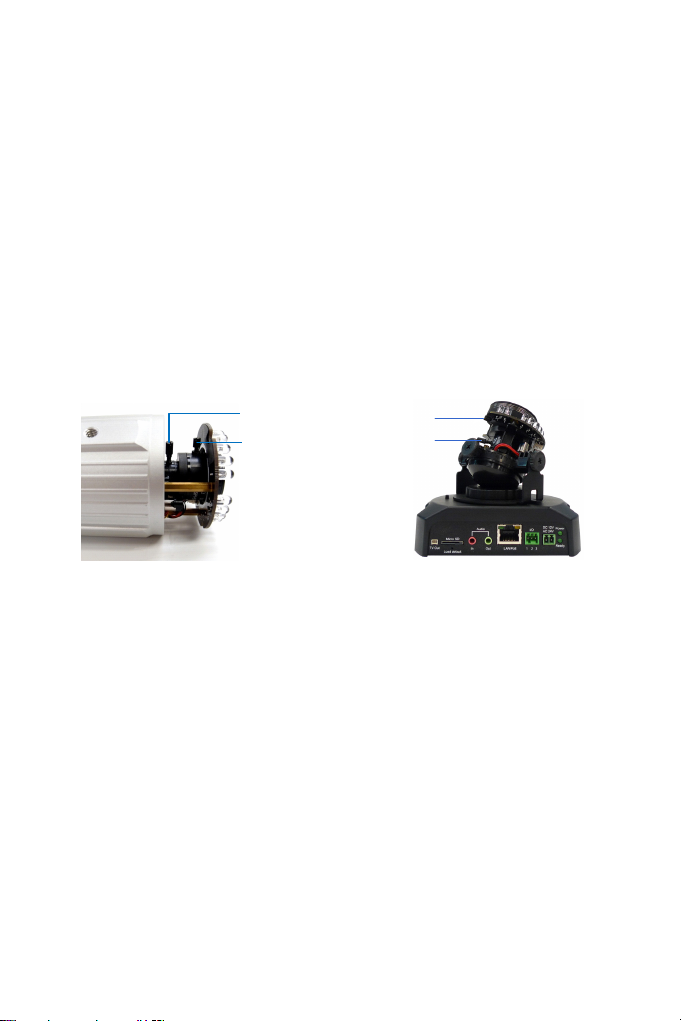
1 Silica gel bag
2 IR power plug Supplies power to the built-in IR LEDs.
3 Focus Screw Adjusts the focus of the camera.
4 Module screw Holds the module in place.
5 Status LED Turns on when the unit is ready for use.
6 Zoom Screw Adjusts the zoom of the camera.
7 Iris Screw Adjusts the iris of the camera.
Desiccant that keeps the camera housing
dry.
41
Page 70

4.4 Installation
The IR Arctic Box Camera is designed for outdoor use.
1. Mark the installation site and drill four holes for screw anchors.
2. Insert the supplied screw anchors.
3. Secure the camera to the wall using the supplied washers and screws.
Figure 4-2
4. Connect the camera to the network and supply power via the PoE
cable. See 4.5 Connecting the Camera.
5. Access the live view. See 14.1 Accessing the Live View.
6. Based on the live view, adjust the angle of the camera. Loosen the
indicated screw with the supplied big torx wrench and adjust the joint.
42
Figure 4-3
Page 71

Tilt Adjustment
Figure 4-4
Pan Adjustment
Figure 4-5
IR Arctic Box Camera
4
7. Based on the live view, adjust the focus, zoom and iris (in GV-
BX520D-E and GV-BX5300-E only) of the camera.
Unscrew the cover with the supplied small torx wrench.
Figure 4-6
43
Page 72

Hold the connectors and unplug them.
Figure 4-7
IMPORTANT: Unscrew and remove the cover carefully. Pulling the
cover off may cause damages to the inner wiring of the camera.
Adjust the focus, zoom and iris screws.
44
Figure 4-8
Page 73

IR Arctic Box Camera
4
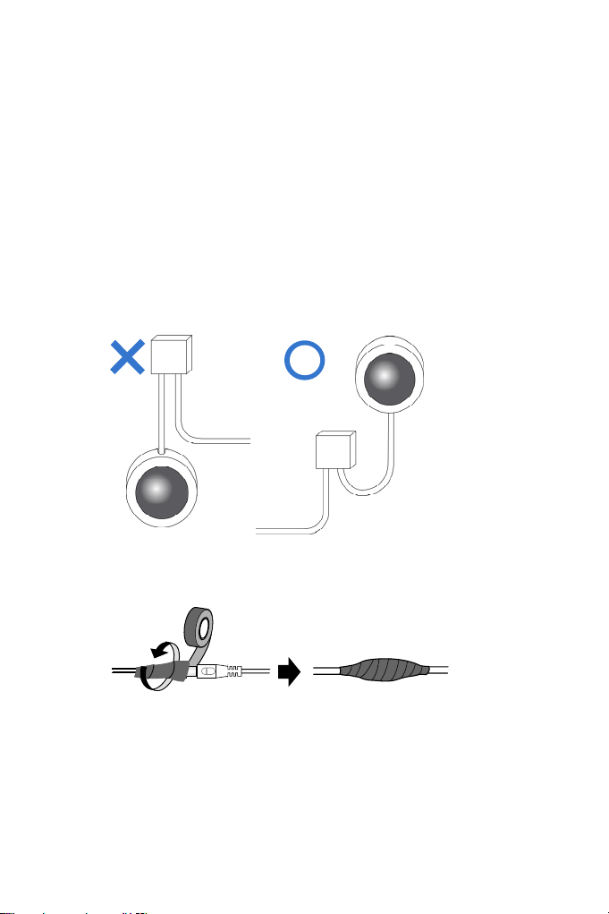
8. Replace the silica gel bag. Paste the sticker to the front side of the
silica gel bag. Press the sticker several times to make sure it adheres
properly. Paste the silica gel bag to the indicated place.
Figure 4-9
IMPORTANT:
1. The gel bag loses its effectiveness when the dry camera is
opened. To prevent the lens from fogging up, replace the silica gel
bag every time you open the camera, and conceal the silica gel
bag in the camera within 2 minutes of exposing to open air.
2. Allow the silica gel bag to absorb moisture for at least 5 hours
before operating the camera.
9. Refer to step 7 to plug the connectors and secure the camera cover.
45
Page 74

4.5 Connecting the Camera
4.5.1 Wire Definition
Figure4-10
No. Wire Color Definition
1 Black (thick) PoE
2 Black BNC TV out
3 Green RCA Audio Out
4 Pink RCA Audio In
1. Optionally connect a speaker (green) and an external microphone
(pink).
2. Optionally connect a monitor using a Video Out wire. Enable this
function by selecting your signal format at the TV Out field on the
Web interface. See 16.1.1 Video Settings.
46
Page 75

IR Arctic Box Camera
4
3. Connect the camera’s cable to the GV-PA481 PoE adapter as
illustrated below. The power and network will be supplied
simultaneously.
Figure 4-11
4. The status LED of the camera will be on.
5. You are ready to access the live view, adjust the image clarity and
configure the basics. See Getting Started, Chapter 14.
47
Page 76

4.6 Notice for Using the IR Arctic Box Camera
Ensure that you:
• enable IR LED function on the Web interface after loading the default
settings.
• disable the status LED to reduce reflection when a green light spot
appears on the live view.
4.6.1 Enabling IR LED after Loading Default
Each GV-IR Arctic Box Camera is equipped with 4 IR LEDs to provide
infrared illumination at night. The factory-loaded setting for the IR LED
function is enabled. If you have restored the camera to default settings,
please follow the steps below to enable the IR LED function.
1. In the left menu of Web interface, select Video Settings and then
Streaming 1.
2. Enable Trigger IR by D/N in IR Check Function.
3. Click Apply.
48
Figure 4-12
Page 77

IR Arctic Box Camera
4
4.6.2 Disabling Status LED under Low Light Conditions
If you have a green light spot on the live view, this is likely due to
insufficient light at the installation site, which causes the status LED to
reflect on the camera cover. In this case, it is advisable that you disable the
status LED.
1. In the left menu of Web interface, select Video Settings and then
Streaming 1.
2. Select Disable in LED Control.
3. Click Apply.
Figure 4-13
49
Page 78

Chapter 5 Mini Fixed Dome & Mini
Fixed Rugged Dome
The Mini Fixed Dome is a fixed, mini-sized ceiling-mount network camera.
Two series are available, the Mini Fixed Dome series, which are designed
for indoor surveillance, and the Mini Fixed Rugged Dome series for outdoor
environments (IP67 and IK10). Both series are and are adjustable in 2-axis
(pan and tilt for GV-MFD series) or in 3 axis (pan, tilt and rotate for GV-
MDR series) and can be connected through PoE.
Model No. Specifications Description
Megapixel, Fixed
GV-MFD120
GV-MDR120
GV-MFD130
GV-MFD220
GV-MFD320
GV-MFD520
GV-MDR220
GV-MDR320
GV-MDR520
GV-MDR2400-0F
GV-MDR3400-0F
(Coming)
GV-MDR2400-1F
GV-MDR2400-2F
GV-MDR3400-1F
GV-MDR3400-2F
(Coming)
Fixed Lens
Iris, f: 4.05 mm,
F/1.5, 1/3’’ M12
Mount
Megapixel, Fixed
Iris, f: 2.54 mm,
F/2.8, 1/2.5’’ M12
Mount
Megapixel, Fixed
Iris, f: 4 mm,
F/1.5, 1/3’’, M12
Lens
Megapixel, Fixed
Iris, f: 8 / 12 mm,
F/1.6, 1/3’’, M12
Lens
1.3 MP, H.264,
Low Lux, Color
1.3 MP / 2 MP /
3 MP / 5MP,
H.264, Color
2 / 3 MP H.264,
Color, WDR Pro
2 / 3 MP H.264,
Color, WDR Pro
Page 79

Mini Fixed & Rugged Dome
5
5.1 Packing List
• Mini Fixed Dome or Mini Fixed Rugged Dome
• Torx Wrench
• Self Tapping Screw x 2
• Screw Anchor x 2
• Cable stopper x 1
• Cable Connector x 1 (for GV-MDR series only)
• Installation sticker (for GV-MDR series only)
• Silica gel bag x 2 (for GV-MDR series only)
• Ferrite core for vehicle installation
• 2-pin terminal block (for GV-MFD series only)
• GV-IPCAM H.264 Software CD
• GV-IPCAM H.264 Quick Start Guide
• GV-NVR Software DVD
• GV-NVR Quick Start Guide
Note: Power adapter can be purchased for Mini Fixed Dome upon
request.
51
Page 80

5.2 Features
• 1/3’’ progressive scan CMOS
• Megapixel lens
• Dual streams from H.264 or MJPEG
• Frame rate:
Camera Model Frame Rate
GV-MFD120
GV-MFD130
GV-MDR120
GV-MFD220
GV-MDR220
GV-MDR2400 Series
GV-MFD320
GV-MDR320
GV-MDR3400 Series
GV-MFD520
GV-MDR520
• Day and night function (electronic)
• Wide Dynamic Range (WDR)
• Defog
• Vandal resistance (IK10 for metal casing, GV-MDR series only)
• Ingress protection (IP67) (for GV-MDR series only)
• EN50155 compliance for rolling stock applications (for GV-MDR
series only)
• Endurable to low environment temperatures (-30°C ~ 50°C / -22°F ~
122°F) (for GV-MDR series only)
Up to 30 fps at 1280 x 1024
Up to 30 fps at 1920 x 1080
Up to 20 fps at 2048 x 1536
Up to 10 fps at 2560 x 1920
52
Page 81

Mini Fixed & Rugged Dome
5
• 2-axis mechanism (GV-MFD series); 3-axis mechanism (GV-MDR
series)
Camera Type Pan Tilt Rotate
GV-MFD series -45° ~ +45° 0° ~ 90° N/A
GV-MDR series -45° ~ +45° 0° ~ 90° 0° ~ 360°
• Micro SD memory card slot (SDHC / SDXC for class 6 or above)
• Built-in microphone
• Motion detection
• Tampering alarm
• Privacy mask
• Text overlay
• IP address filtering
• Support for iPhone, iPad, Android and 3GPP
• 31 languages on Web interface
• ONVIF (Profile S) conformant
53
Page 82

5.3 Overview
5.3.1 GV-MFD120 / 130 / 220 / 320 / 520
1 2 43
5
6
7
Figure 5-1
No. Name Description
1 Default Button
2 Lens Receives image inputs.
3 Tilt Screw Loosens the screw to adjust tilt angle.
4 Built-In Microphone Provides one-way audio.
5 Pan Screw Loosens the screw to pan.
6 LED Indicators See LED Indicators below.
7 Memory Card Slot
54
Resets the camera to factory default. See
18.3 Restoring to Factory Default Settings.
Inserts a micro SD card (SDHC / SDXC for
class 6 or above) to store recording data.
Page 83

Mini Fixed & Rugged Dome
5
LED Name Description
1. Link Turns on when the network is connected.
2. ACT Turns on when data are being transmitted.
3. PWR Turns on when power is on.
4. SW RDY (Status) Turns on when the system is ready.
55
Page 84

5.3.2 GV-MDR120 / 220 / 320 / 520
1
2
No. Name Description
1 Silica gel bag Absorbs the moisture inside the camera.
2 Conceal paper
3 Lens Receives image inputs.
4 Rotation Disc Rotates the camera lens.
5 Pan Disc Pans the camera lens.
6 Tilt Screw Loosens to tilt the camera.
7 Built-In Microphone Provides one-way audio.
8 Default Button
8
9
10
Figure 5-2
Prevents water or moisture from entering
the camera.
Resets the camera to factory default. See
18.3 Restoring to Factory Default
Settings.
56
Page 85

Mini Fixed & Rugged Dome
5
No. Name Description
Power and status
9
LED
10 LAN LED Turns on when the network is connected.
11 Memory Card Slot
IMPORTANT: In case of damage and possible condensation inside the
camera housing, be sure not touch or remove the conceal paper.
Turns red when the power is on. Flashes
orange light twice when the system is
ready.
Inserts a micro SD card (SDHC / SDXC
for class 6 or above) to store recording
data.
57
Page 86

5.4 Installation
To install a Mini Fixed Dome, make sure the installing site is shielded from
rain and moisture.
5.4.1 GV-MFD Series
1. Unscrew the housing cover using the supplied torx wrench.
2. Put the camera on the desired location and make 2 marks on the
ceiling for screw anchors. If you want to run the cables inside the
ceiling, make a round mark with a diameter of 2.5 cm.
3. Drill the marks and insert the screw anchors.
4. Secure the Mini Fixed Dome to the ceiling with the self-tapping
screws.
5. Connect the camera to network and power. For details, see 5.5
Connecting the Camera.
6. Access the live view. For details, see 14.1 Accessing the Live View.
7. Adjust the angles based on the live view.
58
Pan Adjustment
Figure 4-3
Tilt Adjustment
Figure 4-4
Page 87

Mini Fixed & Rugged Dome
5
8. Insert a Micro SD card (SDHC / SDXC for class 6 or above) into the
memory card slot (No. 7, Figure 5-1).
9. Replace the silica gel bag.
IMPORTANT:
1. The silica gel bag loses it effectiveness when the dry camera is
opened. To prevent the lens from fogging up, replace the silica gel
bag every time you open the camera, and conceal the gel bag in
camera within 2 minutes of exposing to open air.
2. For each newly replaced silica gel bag, allow it to absorb moisture
for at least 5 hours before operating the camera.
10. Secure the housing cover using the supplied torx wrench.
11. Optionally conceal the cable opening with the supplied cable stopper.
Figure 5-5
59
Page 88

5.4.2 GV-MDR Series
1. Paste the installation sticker on the desired location. The arrow should
point toward the direction that the camera faces.
2. Drill one hole on each of the two curves for screw anchors. Drill the
circle (30 mm in diameter) if you want to run the cable into the ceiling.
30 mm
Drill a hole
on each
Figure 5-6
3. Insert the screw anchors.
4. Unscrew the housing cover using the supplied torx wrench.
5. Secure the camera body to the ceiling with the self-tapping screws.
60
Figure 5-7
Page 89

Mini Fixed & Rugged Dome
5
6. Install the cable connector to waterproof the cable. You should have 5
parts:
1 2 3 4
5
Figure 5-8
A. Prepare an internet cable with the RJ-45 connector on one end
only.
Figure 5-9
B. Connect the internet cable to the camera cable.
C. Paste the sticker to the camera cable and slide in all the
components as shown below.
Figure 5-10
61
Page 90

D. Move all the components toward the RJ-45 connector, fit item 4
to item 2, secure item 3 to the camera cable and finally secure
item 5 to item 2 tightly.
Figure 5-11
IMPORTANT: Item 5 must be secured tightly to waterproof the
cable.
7. Access the live view. For details, see 14.1 Accessing the Live View.
8. Adjust the angles based on the live view.
Pan Adjustment
62
Figure 5-12
Page 91

Mini Fixed & Rugged Dome
5
Tilt Adjustment
Figure 5-13
Rotational Adjustment
Figure 5-14
9. Insert a Micro SD card (SDHC / SDXC for class 6 or above) into the
memory card slot (No. 11, Figure 5-2).
10. Replace the silica gel bag.
IMPORTANT:
1. The silica gel bag loses it effectiveness when the dry camera is
opened. To prevent the lens from fogging up, replace the silica gel
bag every time you open the camera, and conceal the gel bag in
camera within 2 minutes of exposing to open air.
2. For each newly replaced silica gel bag, allow it to absorb moisture
for at least 5 hours before operating the camera.
63
Page 92

11. Secure the housing cover using the supplied torx wrench.
12. Optionally conceal the cable opening with the supplied cable stopper.
Figure 5-15
64
Page 93

Mini Fixed & Rugged Dome
5
5.5 Connecting the Camera
Refer to the wire definition and illustrations below to connect the power and
network.
5.5.1 Wire Definition
GV-MFD Series
The data cable provides connections for power and network access. The
wires are illustrated and defined below:
Figure 5-16
No. Wire Color Definition
1 Yellow DC 12V+
2 Orange GND
3 Gray PoE, Ethernet
GV-MDR Series
Power and network connectivity is provided through a PoE cable.
Wire Color Definition
Gray PoE, Ethernet
65
Page 94

5.5.2 Power and Network Connection
For GV-MFD Series, there are two ways to supply power to the camera:
• Use a Power over Ethernet (PoE) adapter to connect the camera to
the network, and the power will be provided at the same time.
• Use the supplied Terminal Block and power adapter. Follow the steps
below to connect the Terminal Block and power adapter.
1. Insert the orange wire of the Mini Fixed Dome to the left pin and the
yellow wire to the right pin of the supplied terminal block.
Figure 4-17
2. Connect the DC 12V Power Adapter to the Terminal Block.
3. Connect the camera to network using a network cable.
66
Terminal Block
Figure 4-18
DC 12V Power Adaptor
Page 95

Mini Fixed & Rugged Dome
5
5.5.3 Vehicle Installation
To install the Mini Fixed Rugged Dome on a vehicle, clip the ferrite core
to the camera cable. In accordance to EN 50155, the ferrite core is used
for reduction of the cable-based and radiated interferences, ensuring stable
image quality. The ferrite core must be attached as close as possible to the
camera with the maximum distance of 15 cm.
Max. 15 cm
Figure 4-19
Ferrite Cor e
67
Page 96

Chapter 6 Bullet Camera
The Bullet Cameras are specifically designed for outdoors and are
weatherproof (IP66 or IP67). They are equipped with IR LEDs for infrared
illumination in night vision applications. The image quality is further
enhanced by WDR Pro (GV-BL2400 / 3400 / 2410 / 3410 only, see 2.2.1
Wide Dynamic Range Pro for details). The motorized varifocal lens models
(GV-BL1210 / 2410 / 3410 / 5310) take the advantage of its motorized
focus/zoom in that the user can remotely adjust the focus and zoom
through the Web interface. The following models are available:
Model No. Specifications Description
GV-BL120D 1.3 MP, H.264, Low Lux
GV-BL130D 1.3 MP, H.264
GV-BL220D 2 MP, H.264
GV-BL320D 3 MP, H.264
GV-BL1200 1.3 MP, H.264, Low Lux
GV-BL1300 1.3 MP, H.264
GV-BL2400 2 MP, H.264, WDR Pro
GV-BL3400
GV-BL1210
GV-BL2410
GV-BL3410
GV-BL5310
Varifocal
Lens
Motorized
Varifocal
Lens
Megapixel, Auto
Iris, f: 3 ~ 9 mm,
F/1.2, 1/2.7’’ ø
14 mm Lens
Mount
3 MP, H.264, WDR Pro
1.3 MP, H.264, 3X
Optical Zoom
2 MP, H.264, WDR Pro,
3X Optical Zoom
3 MP, H.264, WDR Pro,
3X Optical Zoom
5 MP, H.264, 2X Optical
Zoom
Page 97

Bullet Camera
6
6.1 Packing List
• Bullet Camera
• Lens (Megapixel and Built-In 16 IR LEDs)
• Self Tapping Screw x 3
• Plastic Screw Anchor x 3
• Torx Wrench x 2
• Sun-Shield Cover Kit (1 Sun-Shield Cover, 2 Philips Head Screws, 2
Plastic Screw Spacers and 2 Hexagon Screws included)
• Silica Gel Bag x 2
• 2-Pin Terminal Block
• GV-IPCAM H.264 Software CD
• GV-IPCAM H.264 Quick Start Guide
• GV-NVR Software DVD
• GV-NVR Quick Start Guide
Note: Power adapter can be purchased upon request.
69
Page 98

6.2 Features
• Image sensor
Camera Model Image Sensor
GV-BL120D / 1200 / 1210 1/3’’ progressive scan CMOS
GV-BL130D / 1300 / 220D /
320D / 5310
GV-BL2400 / 2410 / 3400 /
3410
• Dual streams from H.264 or MJPEG
• Frame rate
Camera Model Frame Rate
GV-BL120D / 130D / 1200 / 1210 / 1300 30 fps at 1280 x 1024
GV-BL220D / 2400 / 2410 30 fps at 1920 x 1080
GV-BL3400 / 3410 20 fps at 2048 x 1536
GV-BL5310 10 fps at 2560 x 1920
• Intelligent IR
• Motorized varifocal lens for remote focus/zoom adjustment
(for GV-BL1210 / 2410 / 3410 / 5310 only)
• Day and night function (with removable IR-cut filter)
• Wide Dynamic Range Pro (for GV-BL2400 / 2410 / 3400 / 3410 only)
• Defog
• Ingress protection
(IP66 for GV-BL120D / 130D / 220D / 320D)
(IP67 for GV-BL1200 / 1300 / 2400 / 3400 / 1210 / 2410 / 3410 / 5310)
• Vandal resistance (IK10 for metal casing, GV-BL1200 / 1300 / 2400 /
3400 / 1210 / 2410 / 3410 / 5310 only)
• Cable-concealed bracket preventing cable from being cut
• One alarm input and sensor output
• Micro SD memory card slot (SDHC / SDXC for class 6 or above)
• Motion detection
1/2.5’’ progressive scan CMOS
1/3.2’’ progressive scan CMOS
70
Page 99

• Tampering alarm
• Visual automation
• Text overlay
• Privacy mask
• IP address filtering
• DC 12V / AC 24V / PoE
• Megapixel lens
• Support for iPhone, iPad, Android and 3GPP
• 31 languages on Web interface
• ONVIF (Profile S) conformant
Bullet Camera
6
71
Page 100

6.3 Overview
1
2 3 4
Figure 6-1
No. Name Description
1 Memory Card Slot
2 Zoom Screw Holds the zoom lens in place.
3 Focus Screw Holds the focus lens in place
4 Default Button
Receives a micro SD card (SDHC / SDXC
for class 6 or above).
Resets all configurations to factory default.
See 18.3. Restoring to Factory Default
Settings.
72
 Loading...