

Page 1
GV-IP Camera
Quick Start Guide
Box Camera
Ultra Box Camera
Arctic Box Camera
Target Box Camera
Before attempting to connect or operate this product,
please read these instructions carefully and save this manual for future use.
ICH265HISIV112-A
Page 2

© 2018 GeoVision, Inc. All rights reserved.
Under the copyright laws, this manual may not be c opi ed, in whole or in
part, without the written consent of GeoVision.
Every ef
fort has been made to ensure that the information in this manual is
accurate. GeoVision, Inc. makes no expressed or implied warranty of any
kind and assumes no responsibility for errors or omissions. No liability is
assumed for incidental or consequential damages arising from the use of
the information or products contained herein. Features and specifications
are subject to change without notice. Note: no memory card slot or local
storage function for Argentina.
ion, Inc.
GeoVis
9F, No. 246, Sec. 1, Neihu Rd.,
Neihu District, Taipei, Taiwan
Tel: +886-2-8797-8377
Fax: +886-2-8797-8
http://www.geovision.com.tw
Trademark
series products are trademarks of GeoVision, Inc. Windows is the
registered trademark of Microsoft Corporation.
February 2018
s used in this manual: GeoVision, the GeoVision logo and GV
335
Page 3

Caution
Risk of explosion if battery is replaced by an incorrect type.
Dispose of used batteries according to the instructions.
Safety Notice
The GV-IPCAM uses a Lithium battery as the power supply for its internal
real-time clock (RTC). The battery should not be replaced unless required!
If the battery does need replacing, please observe the following:
Danger of Explosion if battery is incorrectly replaced
Replace only with the same or equivalent battery, as recommended by
the manufacturer
Dispose of used batteries according to the manufacturer's inst ructions
Page 4

Contents
Caution.................................................................................i
Safety Notice.......................................................................i
Options .............................................................................. v
Note for Adjusting Focus and Zoom.............................. vi
Note for Installing Camera Outdoor.............................. vii
Note for Closing the Bullet Camera Cover.................. viii
Note for Silica Gel Bags................................................ viii
Note for Waterproofing Failures......................................ix
Note for Recording ............................................................x
Chapter 1 Bullet Camera (Part I)......................................1
1.1 Packing List..............................................................................3
1.2 Overview ..................................................................................4
1.3 Installation................................................................................5
1.3.1 Connecting the Camera ...............................................7
1.3.2 Adjusting the Angles ..................................................12
1.3.3 Adjusting Lens and Inserting a Memory Card.............16
1.3.4 Installing the Sun-Shield Cover..................................19
1.4 Loading Factory Default..........................................................20
1.4.1 Using the Web Interface.............................................20
1.4.2 Directly on the Camera ..............................................21
Chapter 2 Bullet Camera (Part II)...................................22
2.1 Packing List............................................................................25
2.2 Overview ................................................................................27
i
Page 5

2.3 Installation..............................................................................30
2.4 Connecting the Camera..........................................................37
Chapter 3 Bullet Camera (Part III)..................................40
3.1 Packing List............................................................................41
3.2 Overview ................................................................................42
3.3 Installation..............................................................................43
3.3.1 Adjusting the Angles ..................................................47
3.3.2 Adjusting Lens ...........................................................49
3.4 Connecting the Camera..........................................................50
3.4.1 Wire Definition ...........................................................50
3.4.2. Power Connection.....................................................52
3.5 Loading Factory Default..........................................................54
3.5.1. Using the Web Interface............................................54
3.5.2. Directly on the Camera .............................................54
Chapter 4 Ultra Bullet Camera.......................................55
4.1 Packing List............................................................................57
4.2 Overview ................................................................................58
4.3 Installation..............................................................................60
4.3.1 Waterproofing the Cable............................................65
4.3.2 Connecting the Camera .............................................67
4.4 Loading Factory Default..........................................................70
4.4.1 Using the Web Interface.............................................70
4.4.2 Directly on the Camera ..............................................70
Chapter 5 Target Bullet Camera (Part I)........................71
5.1 Packing List............................................................................72
5.2 Overview ................................................................................73
5.3 Installation..............................................................................74
5.4 Connecting the Camera..........................................................78
5.4.1 Wire Definition ...........................................................78
5.4.2 Power Connection......................................................79
ii
Page 6

5.5 Loading Factory Default..........................................................80
5.5.1 Using the Web Interface.............................................80
5.5.2 Directly on the Camera ..............................................81
Chapter 6 Target Bullet Camera (Part II).......................82
6.1 Packing List............................................................................83
6.2 Overview ................................................................................84
6.3 Installation..............................................................................85
6.3.1 Adjusting the Angles ..................................................90
6.3.2 Adjusting Lens ...........................................................91
6.4 Connecting the Camera..........................................................92
6.4.1 Wire Definition ...........................................................92
6.4.2 Power Connection......................................................93
6.5 Loading Factory Default..........................................................94
6.5.1 Using the Web Interface.............................................94
6.5.2 Directly on the Camera ..............................................94
Chapter 7 Target Bullet Camera (Part III)......................95
7.1 Packing List............................................................................96
7.2 Overview ................................................................................97
7.3 Installation..............................................................................98
7.4 Connecting the Camera..........................................................99
7.4.1 Wire Definition ...........................................................99
7.4.2 Power Connection......................................................99
7.5 Loading Factory Default........................................................ 100
7.5.1 Using the Web Interface...........................................100
7.5.2 Directly on the Camera ............................................100
Chapter 8 Accessing the Camera................................101
8.1 System Requirement............................................................101
8.2 Accessing the Live View....................................................... 102
8.2.1 Checking the Dynamic IP Address...........................103
8.2.2 Configuring the IP Address ......................................105
iii
Page 7

8.3 Adjusting Image Clarity.........................................................107
Chapter 9 The Web Interface .......................................110
Chapter 10 Upgrading System Firmware .....................57
iv
Page 8

Options
Optional devices can expand your camera’s capabilities and versatility.
Contact your dealer for more information.
Device Description
The I/O cable is a multi-connector providing I/O, DC
I/O Cable
GV-Mount
Accessories
GV-PA191 PoE
Adapter
GV-POE Switch
Power Adapter
GV-Relay V2
12V power, and audio connectivity for the camera.
Length: 106.8 cm (3.5 ft)
-Mount Accessories provide a comprehensive
The GV
lineup of accessories for installation on ceiling, wall
corner and pole. For details, see GV-Mount
Accessories Installation Guide.
The GV
-PA191 PoE adapter is designed to provide
power and network connection to the cameras over a
single Ethernet cable.
The GV
-POE Switch is designed to provide power
along with network connection for IP devices. The
GV-POE Switch is available in various models with
different numbers and types of ports.
The pow
Ultra Bullet Camera (except GV-BL2511-E / 5311-E),
and Target Bullet Camera. Contact our sales
representatives for the countries and areas
supported.
The GV-Relay V2 is designed to expand the voltage
load of GV IP devices. It provides 4 relay outputs, and
each can be set as normally open (NO) or normally
closed (NC) independently as per your requirement.
er adapter is available for all Bullet Camera,
v
Page 9
Note for Adjusting Focus and Zoom
When adjusting the Focus and Zoom Screws on Bullet Camera, do not
over tighten the Focus and Zoom screws. The screws only need to be as
tight as your finger can do it. It is not necessary to use any tools to get
them tighter. Doing so can damage the structure of lens.
For example,
Zoom Screw
Focus Screw
maximum torque value for all the zoom and focus screws is 0.049 N.m
The
vi
Page 10
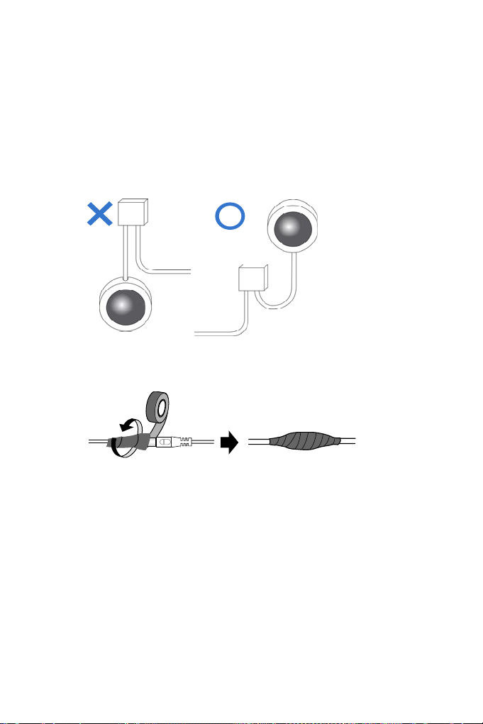
Note for Installing Camera Outdoor
When installing the cameras outdoor, be sure that:
1.
The camera is set up above the junction box to prevent water from
entering the camera along the cables.
Any PoE, power, audio and I/O cables are waterproofed using
2.
waterproof silicon rubber or the like.
vii
Page 11
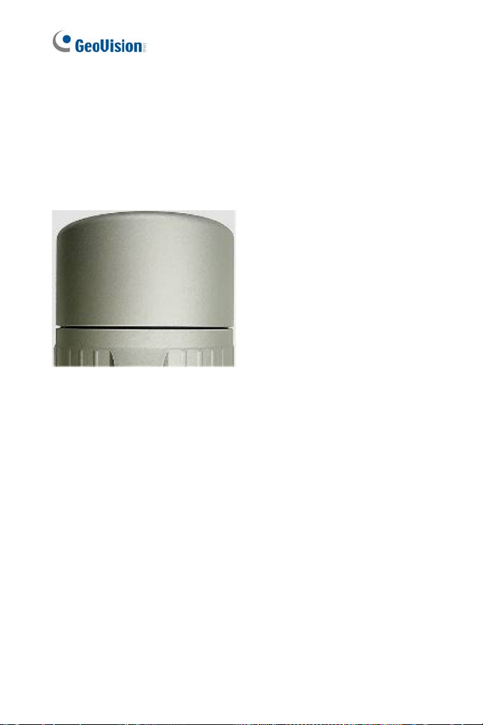
Note for Closing the Bullet Camera Cover
To ensure that the camera performs its full capacity against water and dust ,
tightly close and lock the camera cover as indicated below.
Note for Silica Gel Bags
1. The silica gel bag loses its effectiveness when the dry camera is
opened. To prevent the lens from fogging up, replace the silica gel
bag every time you open the camera, and conceal the gel bag in
camera within 2 minutes of exposing to open air.
2. When the camera is shipped, a silica gel bag will be included insi
he camera. For the first-time user, replace the silica gel bag prior t
t
t
he installation to avoid foggy live view.
de
o
viii
Page 12
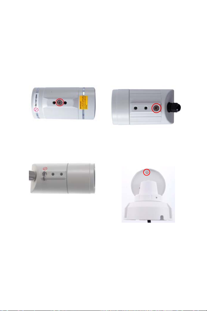
Note for Waterproofing Failures
To avoid waterproofing failures, do not open the screw on the camera body.
The screw on Ultra Bullet
Camera
The screw on GV-EBL2101 /
2111 / 3101 / 5101
The screw on Target Bullet
Camera
The screw on GV-BL3700 /
5700
ix
Page 13

Note for Recording
1. By default, the images are recorded to the memory card inserted in
the GV-IP Camera (except GV-IR Arctic Box Camera, which is not
equipped with a memory card slot). Make sure the Write recording
data into local storage option (see 4.1.1 Video Settings, GV-IPCam
Firmware Manual) is enabled. If this option is disabled, the camera will
stop recording to the memory card while the live view is accessed
through Web browsers or other applications.
2. Mind the following when using a memory card for recording:
Recorded data on the memory card can be damaged or lost if
the data are accessed while the camera is under physical shock,
power interruption, memory card detachment or when the
memory card reaches the end of its lifespan. No guarantee is
provided for such causes.
The stored data can be lost if the memory card is not accessed
for a long period of time. Back up your data periodically if you
seldom access the memory card.
Memory cards are expendable and their durability varies
according to the conditions of the installed site and how they are
used. Back up your data regularly and replace the memory card
annually.
Replace the memory card when its read/write speed is lower
than 6 MB/s or when the memory card is frequently undetected
by the camera.
3. It is recommended to use memory cards of the following setting and
specifications:
Apply a battery backup (UPS) to avoid power outage.
Use Micro SD card of MLC NAND flash, Class 10 for better
performance.
x
Page 14

Bullet Camera (Part I)
1
Chapter 1 Bullet Camera (Part I)
The Bullet Cameras are specifically designed for outdoors and are
weatherproof (IP66 or IP67). They are equipped with IR LEDs for infrared
illumination in night vision applications. The models described in this
chapter use auto iris, which allows for automatic control of exposure.
The WDR Pro models enhance the image by processing contrasting
intensity of light. The super low lux models can produce color live view in
near darkness. The motorized varifocal lens models allow the user to
adjust the focus and zoom through the Web interface.
1
Page 15
Model No. Specifications Description
GV-BL120D 1.3 MP, H.264, Low Lux
GV-BL130D 1.3 MP, H.264
GV-BL220D 2 MP, H.264
GV-BL320D 3 MP, H.264
Va
GV-BL1500
GV-BL2400 2 MP, H.264, WDR Pro
GV-BL2500
GV-BL3400 3 MP, H.264, WDR Pro
GV-BL1210
GV-BL2410
GV-BL3410
GV-BL5310
rifocal
lens
M
otorized
varifocal
lens
Auto Iris, f: 3 ~ 9
mm, F/1.2, 1/2.7’’
ø 14 mm Lens
Mount
Au
to Iris,
f: 3 ~ 9 mm,
F/1.2, 1/2.7’’
ø 14 mm Lens
Mount
Auto Iris,
f: 4.5 ~ 9 mm,
F/1.2, 1/2.7’’
ø 14 mm Lens
Mount
1.3 MP, H.264, Super
Low Lux
P, H.264, Super Low
2 M
Lux
3 MP, H.264, Low Lux,
1.
3X Optical Zoom
2 MP, H.264, WDR Pro,
3X Optical Zoom
3 MP, H.264, WDR Pro,
3X Optical Zoom
5 MP, H.264, 2X Optical
Zoom
2
Page 16

Bullet Camera (Part I)
1
1.1 Packing List
Bullet Camera
Self Tapping Screw x 3
Plastic Screw Anchor x 3
Torx Wrench x 2
S un-Shield Cover Kit (Sun-Shield Cover, Philips Head Screw x 2,
Plastic Screw Spacer x 2 and Hexagon Screw x 2)
Silica Gel Bag x 2
2-Pin Terminal Block
Power Adapter
Download Guide
Warranty Card
Note: The power adapter can be excluded upon request.
3
Page 17
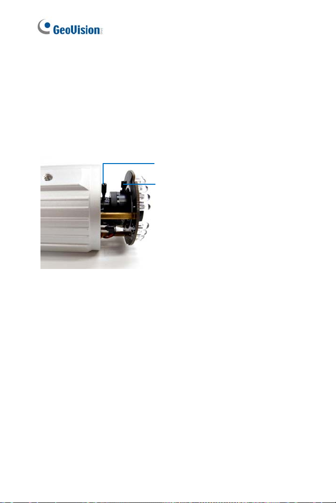
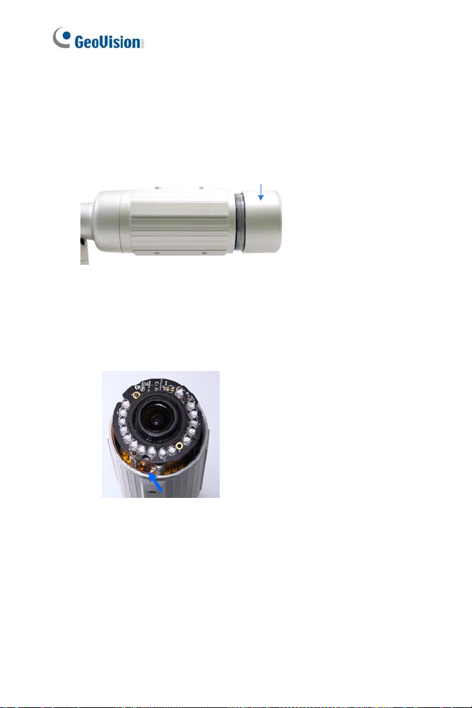
1.2 Overview
1
Figure 1-1
No. Name Description
eceives a micro SD ca r d (SD/SDHC,
1 Memory Card Slot
2 Zoom Screw Holds the zoom lens in p lace.
3 Focus Screw Holds the focus lens in place
4 Default Button
R
version 2.0 only, Class 10).
Resets all configurations to factory default.
For details, see 1.4 Loading Factory Default.
2 3 4
4
Page 18
Bullet Camera (Part I)
1
1.3 Installation
These instructions describe the basic installation of the Bullet Camera.
1. Slide the cable clamp to the camera base.
Cable Clamp
2. Install the Bullet Camera to the wall.
Figure 1-2
3. Remove the protection sticker from the camera’s cover.
4. Connect the power, network and other wires to the Bullet Camera.
See 1.3.1 Connecting the Camera.
Figure 1-3
5
Page 19

5. Access the live view. For details, see 8.2 Accessing the Live View.
6. Adjust angles of the camera body based on the live view. Three
shafts can be adjusted. See 1.3.2 Adjusting the Angles.
7. Loosen the camera’s cover, adjust the focus of the camera and
optionally insert a micro SD card (SD/SDHC, version 2.0, Class 10)
into the SD card slot. See 1.3.3 Adjusting Lens and Inserting a
Memory Card.
8. Fasten the camera’s cover.
9. Install the sun-shield cover to the Bullet Camera. For details, see
1.3.4 Installing the Sun - Shie ld Cover.
6
Page 20
Bullet Camera (Part I)
1
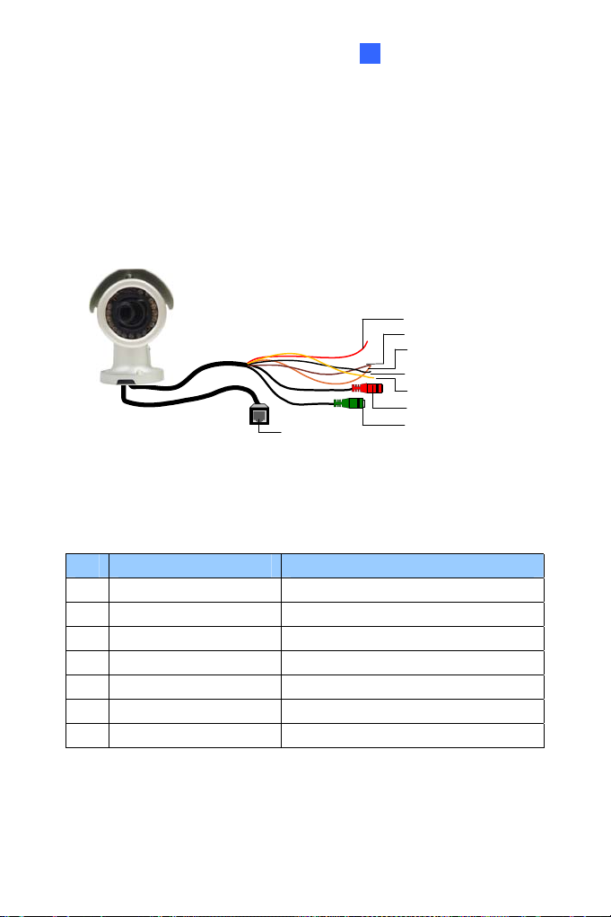
1.3.1 Connecting the Camera
Wire Definition for Auto Iris Models
The 7-Pin Data Cable provides connections for power, ground, 1 sensor
input, 1 alarm output, audio input and audio output. The wires are
illustrated and defined below:
Digital In (Red)
DC 12V+ / AC 24V + (Brown)
Digital Out (Orange)
DC 12V- / AC 24V - (Black)
GND (Yellow)
Audio In (Red)
Ethernet (PoE)
Audio Out (Green)
Figure 1-4
No. Wire Color Definition
1 Red Digital In
2 Brown DC 12V+ / AC 24V+
3 Orange Digital Out
4 Black DC 12V- / AC 24V5 Yellow Ground
6 Red RCA Audio in
7 Green RCA Audio out
7
Page 21
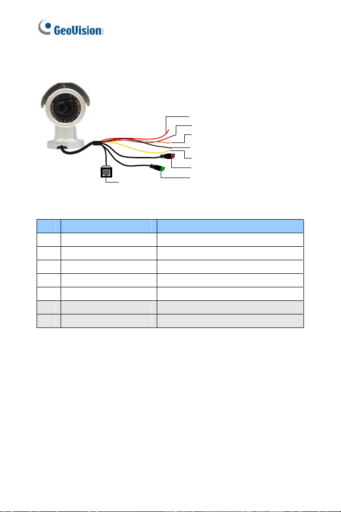
Note that the Audio In and Out connectors may also come as terminal
blocks:
Digital In (Red)
DC 12V+ / AC 24V + (Brown)
Digital Out (Orange)
DC 12V- / AC 24V - (Black)
GND (Yellow)
Audio In (Brown)
Ethernet (PoE)
Audio Out (Green)
Figure 1-5
No. Wire Color Definition
1 Red Digital In
2 Brown DC 12V+ / AC 24V+
3 Orange Digital Out
4 Black DC 12V- / AC 24V5 Yellow Ground
6 Brown terminal block Audio in
7 Green terminal block Audio out
8
Page 22
Bullet Camera (Part I)
1
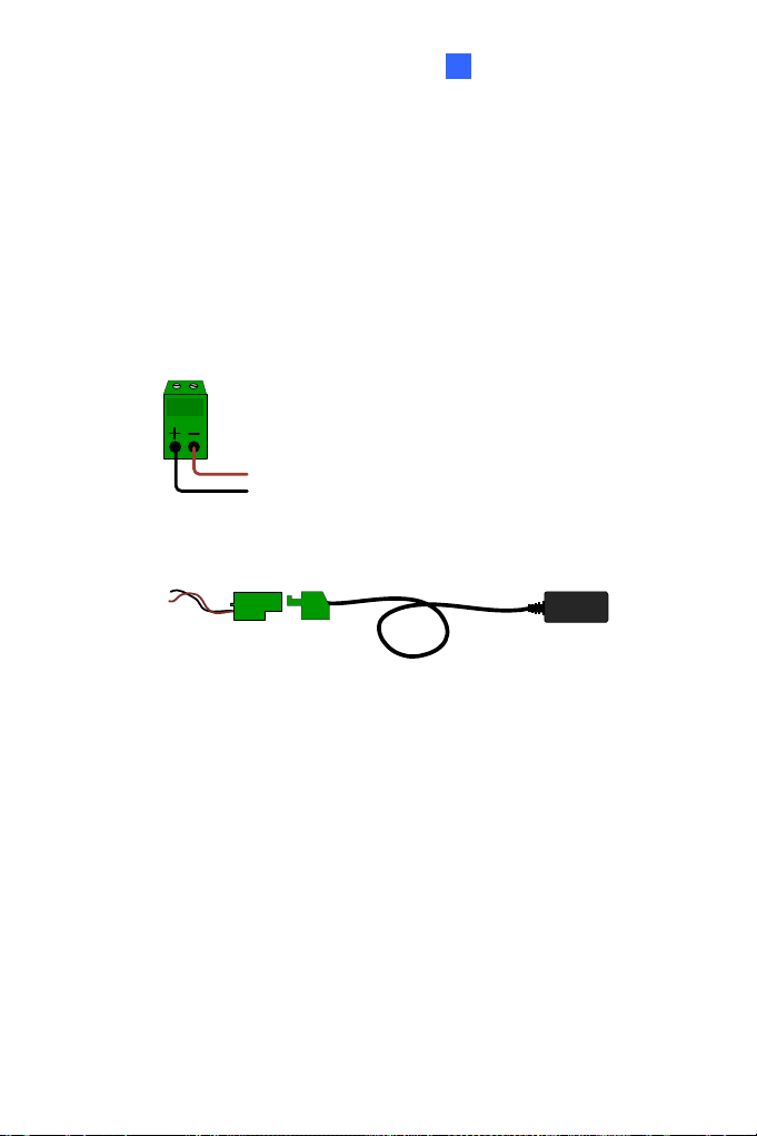
wer Connection
Po
Use one of the following methods to supply power to the camera.
Use a Power over Ethernet (PoE) adapter to connect the camera to
the network, and the power will be provided at the same time.
Plug the power adaptor to the terminal block as shown below.
Insert the black wire of the Bullet Camera to the left pin (+) and
the brown wire to the right pin (-).
Figure 1-6
Connect the DC 12V Power Adapter to the Terminal Block.
Terminal Block
Figure 1-7
DC 12V Power Adaptor
9
Page 23
2
I/O Device Connection
The camera supports one digital input and one digital output of dry contact.
I/O
1
Figure 1-8
For details on how to enable an installed I/O device, see 4.2 I/O Settings,
GV-IPCam Firmware Manual.
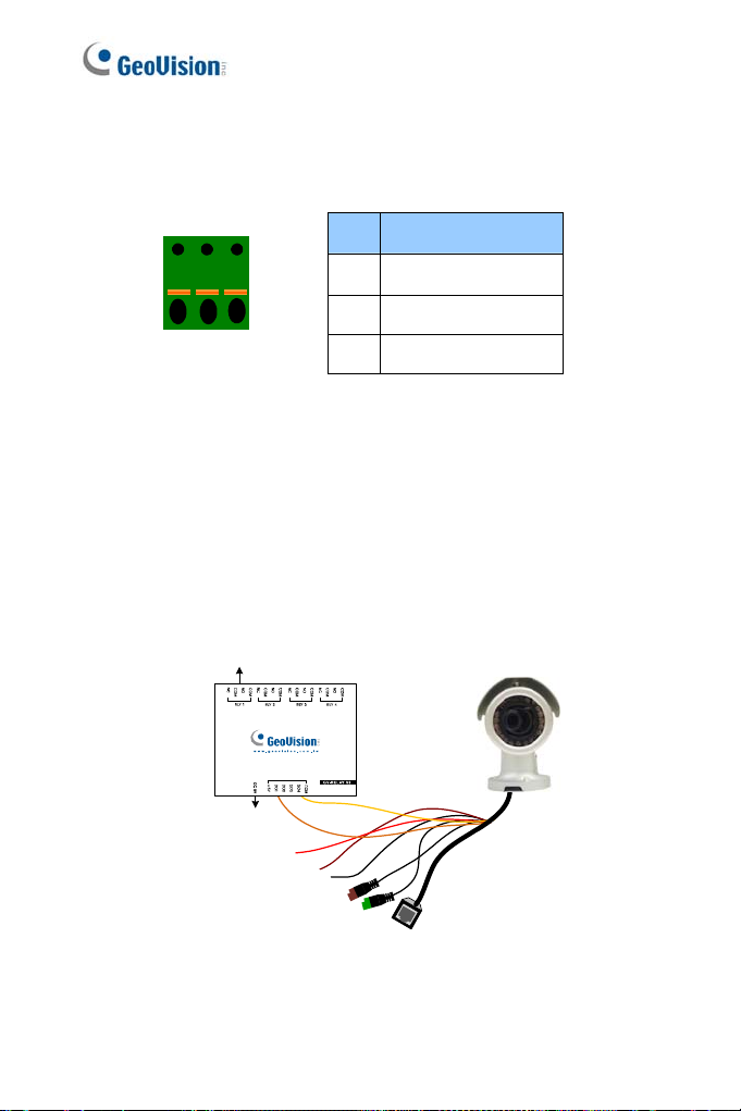
Voltage Load Expansion (Optional)
The camera can only drive a maximum load of 200mA 5V DC. To expand
the maximum voltage load to 10A 250V AC, 10A 125V AC or 5A 100V DC,
connect the camera to a GV-Relay V2 module (optional product). Refer to
the figure and table below.
3
Output Devices
Pin Function
1 Digital Output
2 GND
3 Digital Input
Connect to Power
Figure 1-9
10
Page 24

Bullet Camera (Part I)
1
GV-Relay V2 Bullet Camera
COM Ground (Yellow)
DO1 Digital Out (Orange)
11
Page 25
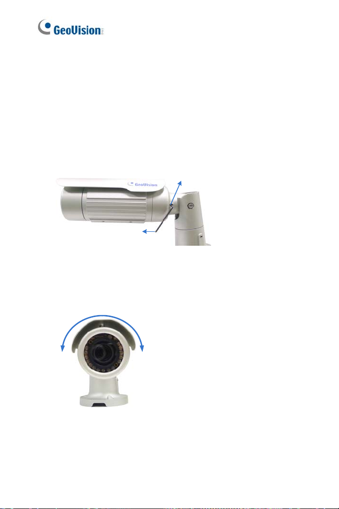
1.3.2 Adjusting the Angles
The Bullet Camera is designed to be adjustable in three shafts for easy
and flexible installation.
First Shaft
You can adjust the camera body by 360 degrees to the right or the left.
1. Unscrew the panning lock screw with the torx wrench.
Panning Lock Screw
Torx Wrench
2. Adjust the angle of camera body to the right or the left, and fasten
the panning lock screw.
Figure 1-10
0 ~ 360°
Figure 1-11
12
Page 26
Bullet Camera (Part I)
1
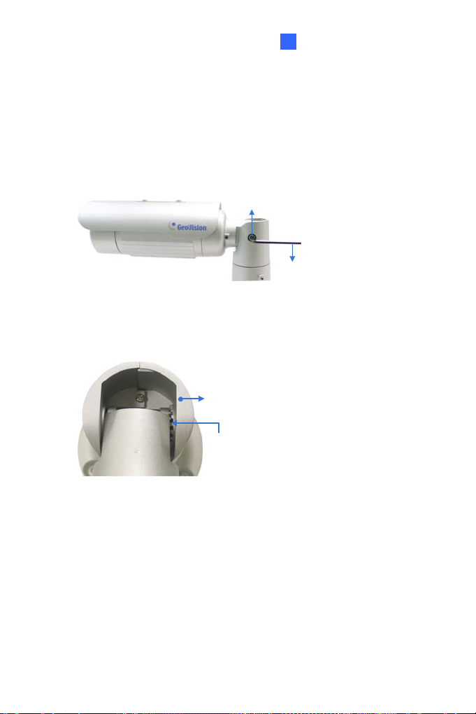
econd Shaft
S
You can adjust the camera body up and down by 90, 112.5, 135, 157.5 or
180 degrees by using the gears inside the camera body and the camera
base.
1. Unscrew the tilting lock screw with the torx wrench.
Tilting Lock Screw
Torx Wrench
Figure 1-12
2. Hold the camera body, and move the camera base to the right to
separate the camera gears.
Move the Camera
Base to the Right
Camera Body
Camera Gears
Figure 1-13
13
Page 27
3. Adjust the angle of camera body to 90°, 112.5°, 135°, 157.5° or 180°.
Then move the camera base to the left to combine the gears.
180°
157.5°
135°
112.5°
90°
Figure 1-14
4. Fasten the tilting lock screw.
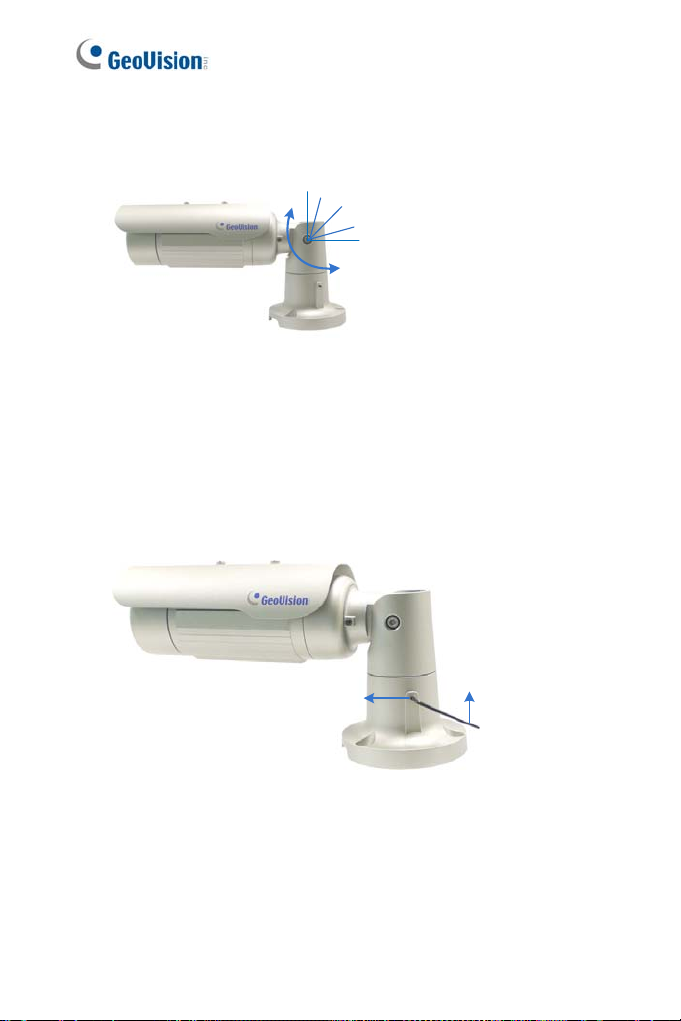
Third Shaf t
You can adjust the camera base by 360°.
1. Unscrew the base fixing screw with the torx wrench.
14
Base Fixing Scre w
Torx Wrench
Figure 1-15
Page 28
Bullet Camera (Part I)
1
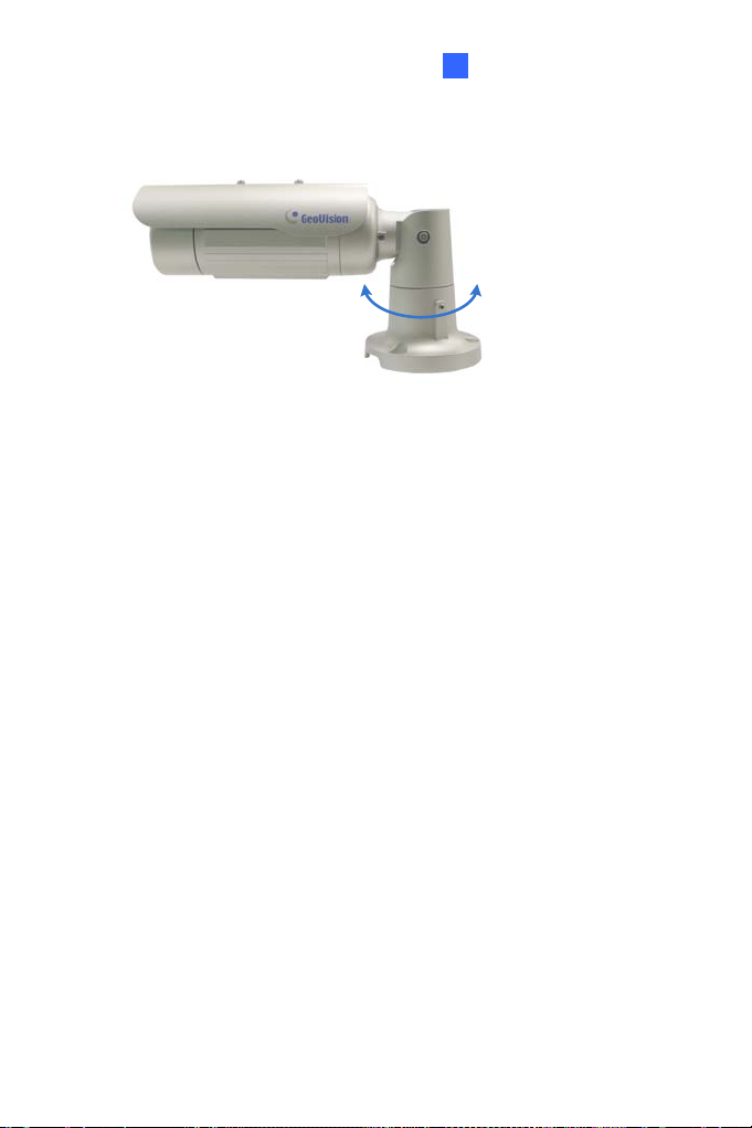
Adjust the angle of camera base, and fasten the base fixing screw.
2.
0~360°
Figure 1-16
15
Page 29
1.3.3 Adjusting Lens and Inserting a Memory Card
To adjust the camera’s zoom and focus or to insert a micro SD card
(SD/SDHC, version 2.0 only, Class 10), follow the steps below.
1. Loosen the camera’s cover.
Camera’s Cover
Figure 1-17
For GV-BL2511-E / 5311-E, loosen the camera’s cover and the screw
as indicated below.
16
Figure 1-18
Page 30
Bullet Camera (Part I)
1
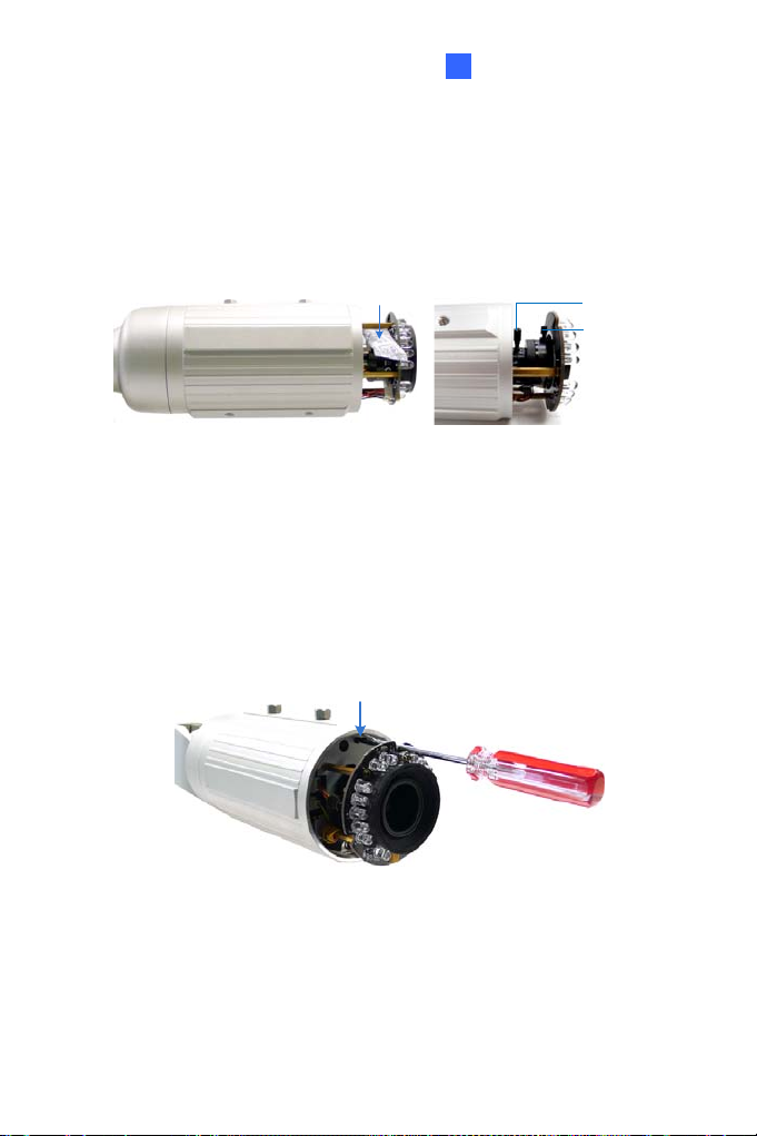
To adjust for image clarity, follow the steps below.
2.
For models with zoom and focus screws, pull out the camera
and remove the silica gel bag to access its focus and zoom
screws. Use GV-IP Device Utility to help you. For details, see 8.3
Adjusting Image Clarity.
Silica Gel Bag
Figure 1-19
For motorized varifocal lens models, adjust for image clarity
through the Web interface. For details, see Zoom, Focus Change,
and Focus Mode settings in 3.2.2 The Control Panel of the Live
View Window, GV-IPCam Firmware Manual.
3. To insert a micro SD card, follow the steps below.
4. Loosen the fixing screw.
Fixing Screw
Figure 1-20
Zoom Screw
Focus Screw
5. Slightly pull out the camera module.
17
Page 31

6. Insert a micro SD card into the memory ca r d sl o t.
Memory Card Slot
Figure 1-21
7. Push the camera back and fasten the fixing screw.
8. Insert a new silica gel bag to the camera module and fasten the
camera’s cover.
Silica Gel Bag
Figure 1-22
Figure 1-23 (GV-BL2511-E/5311-E)
18
Page 32

Bullet Camera (Part I)
1
1.3.4 Installing the Sun-Shield Cover
After setting up the Bullet Camera, now you can install the sun-shield cover
to the camera.
1. Fasten the hexagon screws either on top or below the camera.
Hexagon Screws
2. Put the sun-shield cover on top of hexagon screws. Make sure to
aim the rear hexagon screw at the edge of the sun-shield cover’s
aperture for optimal sun-shield performance.
3. Fasten the Philips head screws with the plastic screw spacers.
Figure 1-24
Sun-Shield Cover
Figure 1-25
Philips Head Screw
Plastic Sc rew Space r
Figure 1-26
19
Page 33

1.4 Loading Factory Default
You can restore factory default settings through the Web interface or
directly on the camera.
1.4.1 Using the Web Interface
1. On the left menu of Web interface, select Management and select
Tools. The Additional Tools dialog box appears.
2. Click the Load Default button in the System Settings section.
20
Figure 1-27
Page 34

Bullet Camera (Part I)
1
1.4.2 Directly on the Camera
1. Keep the power and network cables connected to the camera.
2. Loosen the camera’s cover.
3. Press and hold the default button for 8 seconds.
Default Button
4. the process of loading default
Release the default button. When
settings is completed, the camera reboots automatically.
5. Replace the Silica Gel Bag and fasten the camera’s cove
immediately.
Figure 1-28
r
21
Page 35

Chapter 2 Bullet Camera (Part II)
The Bullet Cameras are specifically designed for outdoors. They are
weatherproof (IP67) and equipped with IR LEDs for infrared illumination in
night vision applications. The models described in this chapter use P-Iris,
which allows for precise control of exposure, producing images with better
clarity and contrast.
The WDR Pro models enhance the image by processing contrasting
intensity of light. The super low lux models can produce color live view in
near darkness. The motorized varifocal lens models allow the user to
adjust the focus and zoom through the Web interface. The arctic models
can withstand extreme temperatures (-40°C ~ 50°C / -40°F ~ 122°F).
22
Page 36

2
Bullet Camera (Part II)
Model No. Specifications Description
3 MP, H.264,
GV-BL1501
GV-BL2501
GV-BL3401
GV-BL2702-3V
GV-BL2702-4V
GV-BL2702-5V
GV-BL4702
GV-BL1511
GV-BL2511
GV-BL3411
Va
rifocal
lens
M
otorized
varifocal
lens
P-
Iris, f: 3 ~ 9 mm,
F/1.2, 1/2.7’’
ø 14 mm Lens
Mount
-Iris, f: 2.8 ~ 12
P
mm, F/1.7, 1/2.7”,
ø 14 mm Lens
Mount
P-Iris, f: 6 ~ 50
mm, F/1.6, 1/2.7”,
ø 14 mm Lens
Mount
P-Iris, f: 9 ~ 22
mm, F/2.0, 1/2.7”,
ø 14 mm Lens
Mount
P-Iris, f: 2.8 ~ 12
mm, F/1.7, 1/2.7”,
ø 14 mm Lens
Mount
P-Iris, f: 3 ~ 9 mm,
F/1.2, 1/2.7’’
ø 14 mm Lens
Mount
1.
Super Low Lux
2 MP, H.264,
Super Low Lux
3 MP, H.264,
WDR Pro
2 MP, H.265,
Super Low Lux,
WDR Pro
4 MP, H.265,
Super Low Lux,
WDR Pro
1.3 MP, H.264,
Super Low Lux,
3X Optical Zoom
2 MP, H.264,
Super Low Lux,
3X Optical Zoom
3 MP, H.264,
WDR Pro, 3X
Optical Zoom
23
Page 37

GV-BL5311
GV-BL4713
GV-BL5713
GV-BL2511-E
GV-BL5311-E
otorized
M
varifocal
lens,
extreme
temperature
tolerance
P-
Iris, f: 4.5 ~ 9
mm, F/1.2, 1/2.7’’
ø 14 mm Lens
Mount
-Iris, f: 2.8 ~ 12
P
mm, F/1.7, 1/2.7”,
ø 14 mm Lens
Mount
P-
Iris, f: 4 ~ 8 mm,
F/1.63, 1/1.8”,
ø 14 mm Lens
Mount
P-Iris, f: 3 ~ 9 mm,
F/1.2, 1/2.7’’
ø 14 mm Lens
Mount
P-Iris, f: 4.5 ~ 9
mm, F/1.2, 1/2.7’’
ø 14 mm Lens
Mount
5 MP, H.264, 2X
Optical Zoom
4 MP, H.265,
Super Low Lux,
WDR Pro
5 MP, H.265,
Low Lux, WDR
2 MP, H.264,
Super Low Lux,
3X Optical Zoom
5 MP, H.264, 2X
Optical Zoom
24
Page 38

2
Bullet Camera (Part II)
2.1 Packing List
For GV-BL1501 / 2501 / 3401 / 1511 / 2511 / 3411 / 5311 / 2511-E /
5311-E, refer to the following packing list:
Bullet Camera
Self Tapping Screw x 3
Plastic Screw Anchor x 3
Torx Wrench x 3
Sun-Shield Cover Kit (Sun-Shield Cover, Philips Head Screw x 2,
Plastic Screw Spacer x 2, and Hexagon Screw x 2)
Silica Gel Bag x 2
2-Pin Terminal Block
3-Pin Terminal Block
Power Adapter
Installation Sticker
Ruler
Stand Kit (Conduit Converter, PG21 Conduit Connector, RJ-45
Connector, M3 Screw x 2, Cable Tie)
Mounting Kit (M4 Screw x 3, Nut x 3, Plate x 3)
Download Guide
Warranty Card
Note:
1. The power adapter can be excluded upon request.
2. The Mounting Kit is used for wall corner and pole installations using
GV-Mount300 / 310 / 400 / 410 (optional). For details, see GV-Mount
Accessories Installation Guide.
25
Page 39

For GV-BL2702 / 4702 / 4713 / 5713, refer to the following packing list:
H.265 Bullet Camera
Stand Kit (Conduit Converter, PG21 Conduit Connector, RJ-45
Connector, M3 Screw x 2, Cable Tie)
Sun-Shield Cover Kit (Sun-Shield Cover, Philips Head Screws x 2,
Plastic Screw Spacers x 2, Hexagon Screws x 2)
Mounting Kit (M4 Screw x 3, Nut x 3, Plate x 3)
Screw Anchor x 3
Screw for Mounting Kit x 3
Hex Wrench
4 mm Wrench
2.5 mm Wrench
Silica Gel Bag x 2
Ruler
Installation Sticker
Download Guide
Warranty Card
Note:
1. GV-BL4713 / 5713 does not include the Sun-Shield Cover Kit in the
packing list since the sun-shield cover is installed to the camera
upon delivery.
2. The Mounting Kit is used for wall corner and pole installations using
GV-Mount300 / 310 / 400 / 410 (optional). For details, see GV-
Mount Accessories Installation Guide.
26
Page 40

2
2.2 Overview
Twist off the camera cover to access the following:
Bullet Camera (Part II)
1
2 3 4
Figure 2-1
GV-BL4713 / 5713
For GV-BL4713 / 5713, twist off the camera cover and loosen the three
screws on the front lid of the sun-shield cover to access the following:
4
1
Figure 2-2
27
Page 41

No. Name Description
eceives a micro SD ca r d (SD/SDHC,
1 Memory Card Slot
2 Zoom Screw Holds the zoom lens in p lace.
3 Focus Screw Holds the focus lens in place
4 Default Button
Note:
1. The memory card slot of GV-BL2702 / 4702 / 4713 / 5713 supports
micro SD card (SD/SDHC/SDXC/UHS-I, Class 10).
2. To insert an SD card into GV-BL4713 / 5713, loosen the screw
indicated in the following left picture, and then open the sun-shield
cover to acces s th e SD card slot.
R
version 2.0 only, Class 10).
ets all configurations to factory default.
Res
For details, see 1.4 Loading Factory Default.
Figure 2-3
28
Page 42

2
Bullet Camera (Part II)
To
access the following interface, remove the camera base using the
supplied torx wrench.
2 3 4 5
1
Figure 2-4
No. Name Description
1 LAN / PoE Connects to a 10/100 Ethernet or PoE.
2 Audio In Connects a microphone for audio input.
3 Audio Out Connects a speaker for audio output.
4 I/O Terminal Block
5 DC 12V Port Connects to power.
Connects to I/O devices. For details, see
I/O Terminal, 2.4 Connecting the Camera.
29
Page 43

2.3 Installation
Follow the steps below to install the Bullet Camera.
1. Paste the supplied sticker to the ceiling/wall. For wall installations,
make sure the arrow on the sticker points toward the ceiling.
Mount template
Figure 2-5
2. Drill the shaded area, and insert the screw anchor into the three
holes.
3. Loosen the indicated screws with the supplied torx wrench to
remove the base.
Figure 2-6
30
Page 44

2
Bullet Camera (Part II)
4.
Loosen the indicated screws and remove the back plate.
Figure 2-7
5. Align and secure the black plate to the wall/ceiling with the supplied
self-tapping screws.
Back Plate
Figure 2-8
31
Page 45

6. To use a pipe (optional), install the conduit converter using the
supplied M3 screws.
Conduit Converter
PG21 Conduit Connector
Figure 2-9
IMPORTANT: For GV-BL2511-E / 5311-E connected with a power
adapter, only install the conduit converter to the indicated exit.
7. Install the Ethernet cable.
A. Twist off and remove the cable seal and the conduit connector.
32
Conduit Connector
Cable Seal
Figure 2-10
Page 46

2
Bullet Camera (Part II)
B
. Thread an Ethernet cable (with no RJ-45 connector on one end)
from the back panel through the conduit converter (optionally
installed at step 6) and then through the cable seal.
Figure 2-11
IMPORTANT: Use the suppl i ed ruler and leave about 10 cm of the
Ethernet cable between the connector and the cable seal.
C. Re-install the cable seal. Make sure it is installed tightly to
waterproof the camera.
8. Thread wires into the camera.
A. Disintegrate the removed conduit connector. You should have 4
parts:
1 2
Figure 2-12
3 4
33
Page 47

B. Remove the terminal block from the supplied power adapter.
C. Optionally thread audio wires, adapter wires, and I/O wires
through the conduit converter and then through part 1, 2, 3, and 4
of the conduit connector.
Tip: To make the threading easier, it is advised to thread the wires in the
order described here.
For part 2, there are 8 holes each labeled with its diameter.
Remove the plugs and push the wires to the corresponding hole
listed below:
Plug
Figure 2-13
34
.6 mm: Audio
2
2 mm: DC12V / A
1.8 mm: DIDO
Figure 2-14
C24V
Page 48

2
Bullet Camera (Part II)
IM
PORTANT:
Use the sup
I/O wires bet
The plugs are used to prevent water from entering the camera
housing. Keep the unused holes plugged and save the r
plugs for future use.
Only thread the wires through their designated holes on the condu
connector to make su
9
. Install the base to the back plate on the wall.
10. Connect the wires to the camera.
A. Install the terminal blocks to t
B. Install the supplied RJ-45 connector to the Ethernet cable.
C. Plug all the connectors to the camera panel.
11. Tie the wires with the supplied cable tie and re-inst
camera. You may need to rotate the base for the w
plied ruler and leave about 10 cm of audio, power, and
ween their connectors and the cable seal.
re the wires are properly sealed.
he power adapter and I/O devices.
See Power Connection and I
Connecting the Camera.
/O Device Connections in 2.4
all the base to the
ires to fit.
emoved
it
Cable Tie
Figure 2-15
35
Page 49

12. r details, see 8.2 Accessing the Live View.
Access the live view. Fo
13. Adjust the angles of the camera based on the live view. Three shaft
can be adjusted. See 1.3.2 Adjusting the Angles.
14. To adjust the focus and insert a micro SD card, see 1.3.3 Adjusting
Lens and Inserting a Memory Card.
15. Install the sun-shield cover. For details, see 1.3.4 Installing t he Sun-
Shield Cover.
s
36
Page 50

2
Bullet Camera (Part II)
2.4 Connecting the Camera
Power Connection
Use one of the following methods to supply power to the camera. Note that
GV-BL2511-E / 5311-E do not support PoE.
Use a Power over Ethernet (PoE) adapter to connect the camera to
the network, and the power will be provided at the same time.
Plug the power adaptor to the terminal block as shown below. For all
models (except GV-BL2511-E / 5311-E), insert the striped wire to the
left pin (+); for GV-BL2511-E / 5311-E, insert the striped wire to the
right pin (-).
Figure 2-16 (All Models except GV-BL2511-E / 5311-E)
Figure 2-17 (GV-BL2511-E / 5311-E)
37
Page 51

2
I/O Device Connection
The camera supports one digital input and one digital output of dry contact.
I/O
1
Figure 2-18
For details on how to enable an installed I/O device, see 4.2 I/O Settings,
GV-IPCam Firmware Manual.
3
Pin Function
1 Digital Output
2 GND
3 Digital Input
I/O Cable (Optional)
For GV-BL2702 / 4702 / 4713 / 5713, you can optionally purchase an I/O
cable for convenient connection.
1
2
3
4
38
Page 52

2
Bullet Camera (Part II)
No. Wire Definition
1 2-pin Terminal Block DC 12V
2 Pink RCA Audio Input
3 Green RCA Audio Output
Red Digital Output
4 Digital I/O
Black GND
Yellow Digital Input
Note: To
terminal block on the adapter and connect the wires to the one on the I/O
cable.
connect a power adapter to the I/O cable, take off the 2-pin
39
Page 53

Chapter 3 Bullet Camera (Part III)
The Bullet Cameras are specifically designed for outdoors. They are
weatherproof (IP67) and equipped with IR LEDs for infrared illumination in
night vision applications. They support H.265 video codec to achieve better
video compression while maintaining high qualit y pict ure. The cameras use
P-Iris, which allows for precise control of exposure, producing images with
better clarity and contrast
Model No. Specifications Description
3 MP, H.265,
Super Low
Lux, WDR
pro
5 MP, H.265,
Low Lux,
WDR
GV-BL3700
GV-BL5700
Varifocal
Lens
P-Iris, f: 2.8 ~ 12 mm,
F/1.7, 1/2.7”, ø 14 mm
Lens Mount
P-Iris, f: 4 ~ 8 mm, F/1.65,
1/1.8”, ø 14 mm Lens
Mount
40
Page 54

3.1 Packing List
H.265 Bullet Camera
3
Bullet Camera (Part III)
Sun-shield Cover
Screw for Supporting Rack
x 3
Silica Gel Bag x 2
RJ-45 Connector x 2
Screw for Mounting Kit x 3
Screw for Sunshield
Cover x 2
Screw Anchor x 3
Washer x 2
Hex Wrench
Nut for Mounting Kit x 3
Download Guide Warranty Card
Note: The Mounting Kit is used for wall corner and pole installations
using GV-Mount300 / 310 / 400 / 410 (optional). For details, see GV-
Mount Accessories Installation Guide.
41
Page 55

3.2 Overview
No. Name Description
1.
2. Default Button
3. Focus Screw Holds the focus lens in place
4. Zoom Screw Holds the zoom lens in p lace.
1
Memory Card
Slot
Figure 3-1
Receives a micr o SD ca rd (SD/SDHC/SDXC/
UHS-I, Class 10).
* UHS-II card type is not supported.
ets all configurations to factory default. For
Res
details, see 3.5 Loading Factory Default.
432
42
Page 56

3
Bullet Camera (Part III)
3.3 Installation
You can install the camera to the ceiling or wall. Follow the steps below.
1. Unscrew the camera body, remove the sun-shield mount, and
loosen the camera cover from the camera.
Screws
Camera Cover
Figure 3-2
2. Insert a micro SD card (SD/SDHC/SDXC/UHS-I, Class 10) into the
card slot.
3. Tape two silica gel bags to the camera module.
Figure 3-3
Sun-Shield Mount
Silica Gel Bag
Micro SD Card
43
Page 57

4. Secure the camera cover, fasten the sun-shield mount, and screw
the camera body.
Sun-Shield Mount
Figure 3-4
5. Slide the sun-shield cover onto the top of the camera. Adjust the
position of the cover before fully securing the cover with the washer
and the screw.
Figure 3-5
44
Page 58

3
Bullet Camera (Part III)
6.
Thread the Ethernet cable into the conduit connector.
A. Remove the plug from the conduit connector.
Figure 3-6
B. Disintegrate the removed conduit connec t or. Thread the
Ethernet cable through the 3 parts.
Figure 3-7
C. Assemble the conduit connector.
Figure 3-8
Note: If you can’t plug the self-prepared RJ-45 connector into the jack of
the conduit, it is suggested to use the supplied RJ-45 connector.
45
Page 59

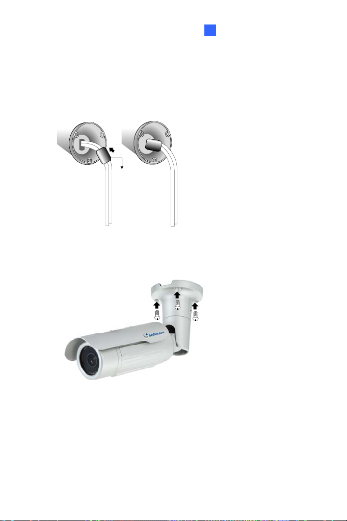
7. Install the camera to the wall or ceiling using the screw anchors and
screws for supporting rack.
Figure 3-9
IMPORTANT: To avoid waterproof i ng failures, the top of the camera
must be facing upward for wall mount.
8. Connect the wires and cable connector to the camera. See 3.4
Connecting the Camera.
9. Access the live view. For details, see 8.2 Accessing the Live View.
10. Adjust angles of the camera body based on the live view.
46
Page 60

3
Bullet Camera (Part III)
3.3.1 Adjusting the Angles
The GV-BL3700 / 5700 is designed to be adjustable in two shafts for easy
and flexible installation.
First Shaft
You can adjust the camera base by 360°.
1. Unscrew the base fixing screw with the hex wrench.
Figure 3-10
2. Adjust the angle of camera base, and fasten the base fixing screw
with the hex wrench.
Figure 3-11
47
Page 61

Second Shaft
You can adjust the camera body to the desired angle by tilting the camera
module.
1. Unscrew the tilting lock screw with the hex wrench.
Figure 3-12
2. Adjust the angle of camera body to the desired angle.
Figure 3-13
3. Fasten the tilting lock screw.
48
Page 62

3
Bullet Camera (Part III)
3.3.2 Adjusting Lens
To adjust the camera’s zoom and focus, follow the steps below.
Loosen the camera’s cover. See Figure 3-2.
To adjust for image clarity by adjusting the focus and zoom screws.
For details, see 8.3 Adjusting Image Clarity.
Focus Screw
Zoom Screw
Figure 3-14
49
Page 63

3.4 Connecting the Camera
3.4.1 Wire Definition
The 4-Pin terminal block supports 1 digital input and 1 digital output of dry
contact. For details on how to enable an installed I/O device, see 4.2 I/ O
Settings, GV-IPCam Firmware Manual. The 5-Pin t erminal block provides
power input, 1 audio input and 1 audio output. The wires are illustrated and
defined below:
Ethernet (PoE)
1
2
4-Pin terminal block
3
4
5
6
7
5-Pin terminal block
8
9
50
Figure 3-16
Page 64

3
Bullet Camera (Part III)
No. Wire Name Definition
1. DI - Digital In -
2. DI + Digital i n +
3. DO - Di gi tal Out -
4.
5. 12V 12 V DC
6. GND DC 12V +
7. L-IN Audio in
8. A GND Audio Ground
9.
Wire Definition
RJ-45 Ethernet / PoE (IEEE 802.3af)
Note: To connect an audio input/output device, cut its 3.5 mm audio jack,
and connect the wires to L-IN and A GND for a microphone or L-OUT and
A GND f or a speaker.
4-pin
terminal
block
5-pin
terminal
block
DO+ Digital Out +
*Support passive microphones only
L-OUT Audio out
Figure 3-17
51
Page 65

3.4.2. Power Connection
Use one of the following methods to supply power to the camera.
Use a Power over Ethernet (PoE) adapter to connect the camera
to the network, and the power will be provided at the same time.
Connect the wires of your power adapter to the DC 12V+ and DC
12V- pins of the 5-pin terminal blocks.
Figure 3-18
52
Page 66

3
Bullet Camera (Part III)
Volt
age Load Expansion (Optional)
The camera can only drive a maximum load of 200mA 5V DC. To expand
the maximum voltage load to 10A 250V AC, 10A 125V AC or 5A 100V DC,
connect the camera to a GV-Relay V2 module (optional product). Refer to
the figure and table below.
Output Devices
Connect to Power
1
2
3
4
5
6
7
8
9
Figure 3-19
GV-Relay V2 Bullet Camera
COM
in terminal block
4-P
Digital In +
Digital Out +
DO1 Digital Out -
53
Page 67

3.5 Loading Factory Default
3.5.1. Using the Web Interface
U You can restore factory default settings through the Web interface. For
details, refer to 1.4.1 Using the Web Interface.
3.5.2. Directly on the Camera
Press and hold the default button for about 5 seconds to restore the
factory default. After the ready LED blinks, release the default button. For
details see 1.4.2 Directly on the Camera.
Default Button
54
LED status
Figure 3-20
Page 68

4
Bullet Camera (Part III)
Chapter 4 Ultra Bullet Camera
The Ultra Bullet Camera is a series of light-weighted cameras designed for
outdoor environments. The camera adheres to the IP67 standard and has
full protection against dust and jets of water. The Ultra Bullet Cameras are
available in motorized varifocal lens and fixed lens at 1.3, 2 and 3
megapixels. The motorized varifocal lens models allow the user to
remotely adjust the focus and zoom through the Web interface. The WDR
Pro models can enhance the live view by processing contrasting intensity
of lights. Th e super low lux models are able to provide color live view in
near darkness.
Model No. Specifications Description
1.
3 MP Low Lux,
GV-UBL1211
GV-UBL1511
GV-UBL2411
GV-UBL2511
GV-UBL3411
rifocal
Va
Lens
Auto Iris, f: 3 ~ 9
mm, F/1.2, 1/2.7’’
ø 14 mm Lens
Mount
H.264, 3X Optical
Zoom
1.
3 MP Super Low
Lux, H.264, 3X Optical
Zoom
2 MP, H.264, WDR
Pro, 3X Optical Zoom
2 MP Super Low Lux,
H.264, 3X Optical
Zoom
3 MP, H.264, WDR
Pro, 3X Optical Zoom
55
Page 69

Model No. Specifications Description
Fixed Iris, f: 2.8 mm,
GV-UBL1301-0F
GV-UBL1301-1F
GV-UBL1301-2F
GV-UBL1301-3F
GV-UBL2401-0F
GV-UBL2401-1F
GV-UBL2401-2F
GV-UBL2401-3F
GV-UBL3401-0F
GV-UBL3401-1F
GV-UBL3401-2F
GV-UBL3401-3F
xed
Fi
Lens
F/2.0, 1/3’’ M12 Lens
Mount
Fixed Iris, f: 4 mm,
F/1.5, 1/3’’ M12 Lens
Mount
ed Iris, f: 4 / 8 mm,
Fix
F/1.6, 1/3’’ M12 Lens
Mount
Fi
xed Iris, f: 2.8 mm,
F/2.0, 1/3’’ M12 Lens
Mount
Fixed Iris, f: 4 mm,
F/1.5, 1/3’’ M12 Lens
Mount
Fi
xed Iris, f: 8 / 12 mm,
F/1.6, 1/3’’ M12 Lens
Mount
Fi
xed Iris, f: 2.8 mm,
F/2.0, 1/3’’ M12 Lens
Mount
Fixed Iris, f: 4 mm,
F/1.5, 1/3’’ M12 Lens
Mount
Fixed Iris, f: 8 / 12 mm,
F/1.6, 1/3’’ M12 Lens
Mount
3 MP, Low
1.
Lux, H.264
1.3 MP, Low
Lux, H.264
P, H.264,
2 M
WDR Pro
P, H.264,
3 M
WDR Pro
56
Page 70

4
Bullet Camera (Part III)
4.1 Packing List
Ultra Bullet Camera (with Waterproof or Non-Waterproof LAN
connector)
Camera Stand
Black Rubber
Self Tapping Screw x 3
Plastic Screw Anchor x 3
Torx Wrench
Sun-Shield Cover Kit (Sun-Shield Cover, Philips Head Screw x 2,
Plastic Screw Spacer x 2 and Hexagon Screw x 2)
Cable connector (for waterproof LAN connector only)
Silica Gel Bag x 2
2-Pin Terminal Block
Data cable
Power Adapter
Download Guide
Warranty Card
Note: The power adapter can be excluded upon request.
57
Page 71

4.2 Overview
Panel
1
3
4
5
2
Figure 4-1
No. Name Description
Power & I/O
1
Connector
2 Default Button
3 LAN / PoE Cable Connects to a 10/100 Ethernet or PoE.
Memory Card
4
Slot
5 Silica gel bag Desiccant that keeps the camera housing dry.
Connects to the data cable. For details, see
4.3.2 Connecting the Camera.
ets all configurations to factory default. For
Res
details, see 4.4 Loading Factory Default.
Receives a micro SD card (SD/SDHC, version
2.0 only, Class 10).
58
Page 72

4
Bullet Camera (Part III)
L
AN Connector
The Ultra Bullet Camera provides two connector types. Select an option
based on your installation environment.
Option 1 (Waterproof)
To waterproof the cable, install the supplied cable connector. See 4.3.1
Waterproofing the Cable.
Option 2 (Smaller and non-waterproof)
59
Page 73

4.3 Installation
You can install the camera to the ceiling or wall. Follow the steps below.
1. Optionally insert a micro SD card to the camera.
A. Unscrew and open the back panel with the supplied torx wrench.
Figure 4-2
B. Insert a micro SD card into the card slot and replace the silica
gel bag (see Figure 4-1).
IMPORTANT: Make sure the I/O connector is firmly plugged.
C. Secure the back cover with the supplied torx wrench.
2. Install the sun-shield cover to the camera.
60
Page 74

4
Bullet Camera (Part III)
A
. Fasten the hexagon screw(s) on the top of the camera.
Hexagon Screws
Fi
gure 4-3
B. Put the sun-shield cover on the top of the camera. For optimal
sun-shield performance, make sure the rear hexagon screw is at
the end of the opening.
Sun-Shield Cover
Figure 4-4
IMPORTANT: The GeoVision logo on the sun-shield cover s houl d
be closer to the front of the camera.
61
Page 75

C. Fasten the Philips head screws with the plastic screw spacers to
mount the sun-shield cover onto the camera.
Ceiling Mount: Fasten one Philips head screw to the top
of the camera.
Wall Mount: Fasten two Philips head screws to the top
of the camera.
Philips Head Screw
Plastic Screw Spacer
Figure 4-5
3. Install the camera stand.
A. Ceiling Mount: Secure the black rubber and the camera stand to
the screw hole on the top.
62
Figure 4- 6
Page 76

4
Bullet Camera (Part III)
B
. Wall Mount: Secure the black rubber and the camera stand to
one of the screw holes on the bottom.
gure 4-7
Fi
4. Use the screw anchors and self-tapping screws to secure the
camera to the wall.
Figure 4-8
63
Page 77

5. Remove the protection sticker from the camera’s cover.
6. Connect the wires and cable connector to the camera. See 4.3.1
Waterproofing the Cable and 4.3.2 Connecting the Camera.
7. Access the live view. For details, see 8.2 Accessing the Live View.
8. Adjust angles of the camera body based on the live view.
9. For varifocal models (GV-UBL1211 / 1511 / 2411 / 2511 / 3411),
adjust the focus. For details, see 3.2.2 The Control Panel of the Live
View Window, GV-IPCam Firmware Manual.
64
Page 78

4
Bullet Camera (Part III)
4.3.1 Waterproofing the Cable
Waterproof the option 1 LAN / PoE cable (see 4.2 Overview) using the
supplied cable connector. The cable connector can be dissembled into 5
parts:
1 2 3 4
5
Figure 4-9
1. Cut off the RJ-45 connector on one end of the Ethernet cable.
Figure 4-10
2. Connect the Ethernet cable to the LAN / PoE connector (No. 3,
Figure 4-1) on the camera.
3. Slide the components through the Ethernet cable as shown below.
1
A
4. Paste the it em 1 sticker to item 2.
2
Figure 4-11
3
5
4
65
Page 79

5. Move all the components toward the LAN / PoE connector, fit item 4
to item 2, secure item 3 to the LAN / PoE connector (Item A) and
finally secure item 5 to item 2 tightly.
Figure 4-12
IMPORTANT: Item 5 must be secured tight l y to waterproof t he
LAN / PoE connector.
6. Prepare an RJ-45 connector, reconnect the RJ-45 connector to the
cable, and then connect the camera to network.
66
Page 80

4
Bullet Camera (Part III)
4.3.2 Connecting the Camera
Wire Definition
The camera’s 4-pin data cable provides connections for power, ground, 1
sensor input and 1 alarm output. The wires are defined below:
Figure 4-13
No. Wire Color Definition
1 Red DC 5V
2 Green Digital In
3 Blue Digital Out
4 Black Ground
67
Page 81

Power Connection
Connect the camera to power using one of the following methods:
Use a Power over Ethernet (PoE) adapter to connect the camera to
the network, and the power will be provided at the same time.
Plug the power adaptor to the terminal block as shown below.
1. Insert the black wire of the data cable to the left pin (-) and
the red wire to the right pin (+).
Figure 4-14
2. Connect the DC 5V power adapter to the terminal block.
Terminal Block
68
DC 5V Power Adaptor
Figure 4-15
Page 82

4
Bullet Camera (Part III)
Volt
age Load Expansion (Optional)
The camera can only drive a maximum load of 200mA 5V DC. To expand
the maximum voltage load to 10A 250V AC, 10A 125V AC or 5A 100V DC,
connect the camera to a GV-Relay V2 module (optional product). Refer to
the figure and table below.
Output Devices
Connect
to power
Figure 4-16
GV-Relay V2 Ultra Bullet Camera
DO1 Digital Out (Blue)
COM Ground (Black)
69
Page 83

4.4 Loading Factory Default
4.4.1 Using the Web Interface
You can restore factory default settings through the Web interface. For
details, refer to 1.4.1 Using the Web Interface.
4.4.2 Directly on the Camera
Press and hold the default button for about 8 seconds to store the factory
default. For details see 1.4.2 Directly on the Camera.
Default button
70
Figure 4-17
Page 84

5
Target Bullet Camera (Part I)
Chapter 5 Target Bullet Camera (Part I)
The Target Bullet Camera is a series of light-weighted cameras designed
for outdoor environments. The camera adheres to the IP67 standard and
has full protection against dust and jets of water. The camera offers an
entrylevel surveillance solution with all the essential features and excellent
image quality.
Model No. Specifications Description
GV-EBL1100-1F
GV-EBL2100-1F
GV-EBL1100-2F
GV-EBL2100-2F
xed
Fi
Lens
Fixed Iris, f: 6 mm,
F/1.8, 1/2.7”, ø 14 mm
Lens Mount
Fixed Iris, f: 3.8 mm,
F/1.8, 1/2.7”, ø 14 mm
Lens Mount
1.3 MP / 2 MP,
H.264, Low
Lux
71
Page 85

5.1 Packing List
Target Bullet Camera
Sun-Shield Cover
Silica Gel Tape x 2
Supporting Rack
Screw for supporting rack x 3
Screw Anchor x 3
Screw for sun- sh i e l d co ver
Washer
Terminal Block
Download Guide
Warranty Card
Note: Power adapter can be purchased upon request.
72
Page 86

5
5.2 Overview
2
1
Figure 5-1
No. Name Description
Power
1
Connector
2 Default Button
Connects to the data cable. For details, see
5.4 Connecting the Camera.
Resets the camera to factory default. For
details, see 5.5 Loading Factory Default.
Target Bullet Camera (Part I)
73
Page 87

5.3 Installation
You can install the camera to the ceiling or wall. Follow the steps below.
1. Slide the sun-shield cover onto the top of the camera.
Figure 5-3
Note: The GeoVision logo on the sun-shield cover should be closer to
the front of the camera.
2. Line up the screw hole on the camera with the opening on the sunshield cover.
74
Figure 5-4
Page 88

5
Target Bullet Camera (Part I)
Ceiling Mount: Secure the supporting rack to the opening on the
3.
sun-shield cover
Figure 5-5
4. Wall Mount:
A. Insert and tighten the supplied screw and washer on the sun-
shield cover.
B. Secure the supporting rack to the bottom.
Figure 5-6
75
Page 89

5. Thread the Ethernet cable into the conduit connector. For details,
see step 6, 3.3 Installation.
Figure 5-7
Note: The size of RJ-45 connector must be within 14 mm to plug into the
jack of the conduit.
Unfit size of RJ45 Connector
76
Page 90

5
Target Bullet Camera (Part I)
Install the camera to the wall or ceiling using the screw anchors and
6.
self-tapping screws. You can also stand the camera on a plain
surface.
Figure 5-8
7. Remove the protection sticker from the camera’s cover.
8. Connect the wires and cable connector to the camera. See 5.4
Connecting the Camera.
9. Access the live view. For details, see 8.2 Accessing the Live View.
10. Adjust angles of the camera body based on the live view.
77
Page 91

5.4 Connecting the Camera
5.4.1 Wire Definition
The data cable provides connections for power, ground and network
access. The wires are defined below:
Figure 5-9
No. Wire Color Definition
1 Red DC 12V
2 Black Ground
3 Black (thick) PoE, Ethernet
78
Page 92

5
Target Bullet Camera (Part I)
5.4.2 Power Connection
There are two ways to supply power to the camera:
Use a Power over Ethernet (PoE) adapter to connect the camera to
the network, and the power will be provided at the same time.
Plug the power adapter to the 12V terminal block as shown below.
The power adapter is an optional device.
1. Insert the black wire of the data cable to the left pin (-) and the red
wire to the right pin (+).
+-
Figure 5-10
2. Connect the DC 12V power adapter to the terminal block.
Terminal Block
DC 12V Power Adaptor
Figure 5-11
Note: The Power Adaptor is not supplied in the packing list. You need
to self-prepare this item.
79
Page 93

5.5 Loading Factory Default
5.5.1 Using the Web Interface
3. On the left menu of Web interface, select Management and select
Tools. The Additional Tools dialog box appears.
4. Click the Load Default button of Restore to factory default
settings or Restore to factory default settings (Except network)
in the System Settings section.
Figure 5-12
Note: The Restore to factory default settings (Except network)
option is to restore the factory default settings without changing the
camera’s network settings.
80
Page 94

5
Target Bullet Camera (Part I)
5.5.2 Directly on the Camera
Press and hold the default button for about 8 seconds to restore the
factory default. For details see 1.4.2 Directly on the Camera.
Default button
Figure 5-13
81
Page 95

Chapter 6 Target Bullet Camera (Part II)
The Target Bullet Camera is a light-weighted camera designed for outdoor
environments. It adheres to the IP67 standard and has full protection
against dust and jets of water. The camera also allows automatic and
precise control of exposure using its P-iris, producing images with better
clarity and contrast. It offers an entrylevel surveillance solution with all the
essential features and excellent image quality.
Model No. Specifications Description
GV-EBL2101
GV-EBL2111
GV-EBL3101
GV-EBL5101
Varifocal
Lens
Motorized
Varifocal
Lens
Varifocal
Lens
Varifocal
Lens
P-Iris, f: 3 ~ 9 mm,
F/1.7, 1/2.7”, ø 14 mm
Lens Mount
P-Iris, f: 2.8 ~ 12 mm,
F/1.7, 1/2.7”, ø 14 mm
Lens Mount
P-Iris, f: 2.8 ~ 12 mm,
F/1.7, 1/2.7”, ø 14 mm
Lens Mount
P-Iris, f: 2.8 ~ 12 mm,
F/1.7, 1/2.7”, ø 14 mm
Lens Mount
P, H.264,
2 M
Super Low
Lux
P, H.264,
2 M
Super Low
Lux
P, H.264,
3 M
Super Low
Lux
5 MP, H.264 ,
Low Lux
82
Page 96

6.1 Packing List
Target Bullet Camera
6
Target Bullet Camera (Part II)
Sun-shield Cover
Screw for Supporting Rack
x 3
Screw for Sun-shield Cover
x 2
Terminal Block
Nut for Mounting Kit x 3
Download Guide
Silica Gel Bag x 2
Screw Anchor x 3
Washer x 2
Screw for Mounting Kit x 3
Hex Wrench
Warranty Card
Note: Power adapter can be purchased upon request.
83
Page 97

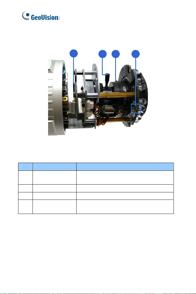
6.2 Overview
3
Figure 6-1
No. Name Description
1 Zo om Screw Holds the zoom l ens in place.
2 Focus Screw Holds the focus lens in place
ets all configurations to factory default. For
3 Default Button
Res
details, see 6.5 Loading Factory Default.
84
Page 98

6
Target Bullet Camera (Part II)
6.3 Installation
You can install the camera to the ceiling or wall. Follow the steps below.
1. Replace the Silica Gel Bag.
A. Remove the camera cover from the camera.
Figure 6-2
B. Loosen the camera’s screws and the hexagon pillars as
indicated below.
Figure 6-3
85
Page 99

C. Take out the camera from the camera body
Figure 6-4
D. Cut the 2 silica gel bags apart with scissors, and place the
new silica gel bags at the lower half of the camera body.
Figure 6-5
2. Secure the 2 hexagon pillars to the upper and lower holes of camera
module as indicated below.
86
Figure 6-6
Page 100

6
Target Bullet Camera (Part II)
. Secure the camera cover.
3
4. Slide the sun-shield cover onto the top of the camera. You can also
secure the sun shield cover onto the back of the camera. Adjust the
position of the cover before fully securing the cover with the washer
and the screw.
Note:
1. The GeoVision logo on the sun-shield cover should be closer to
the front of the camera.
2. There are two holes for the screws at the back of the camera.
You only need to fasten one screw to secure the sun shield
cover.
Figure 6-7
87
 Loading...