

ADAMS
MODEL CD-22
MODEL CD-28
CONTINUOUS DUTY WINCH
Installation, Operation and
Maintenance Manual
General Machine Products Co., Inc.
3111 Old Lincoln Highway Trevose, PA 19053 USA
Tel: +1.215.357.5500 Fax: +1.215.357.6216 Email: info@GMPtools.com
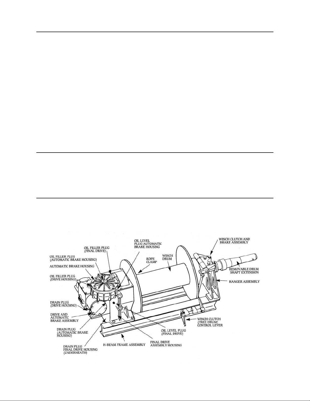
TABLE OF CONTENTS
GENERAL ………………………………………………………………….. Page 2
MAJOR COMPONENTS …………………………………………………... Page 3
ACCESSORIES …………………………………………………………….. Page 3
USE …………………………………………………………………………. Page 3
HYDRAULIC REQUIREMENT …………………………………………... Page 3
INSTALLATION …………………………………………………………... Page 3
CONTROLS ………………………………………………………………... Page 4
WINCH CLUTCH AND DRAG BRAKE INFORMATION .……………... Page 4
CALIPER BRAKE ASSEMBLY INSTALLATION ………………………. Page 6
AUTOMATIC BRAKE …………………………………………………….. Page 6
PREPARING FOR OPERATION………………………………………….. Page 7
OPERATING THE WINCH ………………………………………..………. Page 7
MAINTENANCE …………………………………………………………... Page 8
LUBRICATION ………………………………………………..…………... Page 8
PRECAUTIONS ……………………………………………………………. Page 9
WIRE ROPE INFORMATION …………………………………………….. Page 10
WINCH IDENTIFICATION ……………………………………………….. Page 11
ACCESSORIES …………………………………………………………….. Page 11
BASIC DETAILS CD-22 CD-28
Maximum Rated Pull-Bare Drum 20,000 lbs. 20,000 lbs.
Maximum Rated Pull-Full Drum 9,000 lbs. 9,000 lbs.
Drum Width 22.5” 28”
Net Weight 925 lbs. 935 lbs.
Cube Dimension 24” High X 24” Wide X 60” long 65” long
BASIC DETAILS …………………………………………………………... Page 2
GENERAL
The Model CD-22 and CD-28 winches are derived from Bell System Spec. 8003LlB and 8003-L2B. Differing only in the drum width, they are suitable for applications involving stationary or mobile mounting. Driven by a series of highly
efficient helical gears, these units will not generate excessive heat under long,
maximum pull conditions.
2

MAJOR COMPONENTS
ACCESSORIES
• Winch Drive Assembly
• Final Drive Assembly
• Safety Brake Assembly
• Drum Assembly
• Clutch Assembly
• Drag Brake Assembly
• Hanger
• Frame
Levelwind Model CH-22 or CH-28, Overw i nd o r Un der wind
(Derived from Bell System Spec. 8414).
Three speed transmission-hydromechanical Model 240-584
(Derived from Bell System Spec. 8111).
Three speed transmission-hydraulic Model 230-1600
Drum shaft extension
USE
HYDRAULIC
REQUIRMENT
INSTALLATION
The Models CD-22 and CD-28 can be driven mechanically, hydromechanically
or hydraulically. Both winches have been primarily designed for placing underground communication cable or electrical conductor. However, they can be used
for most applications where a long, continuous pull is required.
Mechanically - for mobile mounting, using the truck engine as the prime source of
power, through a split shaft or side mount power take-off and silent chain drive to
the winch input shaft.
Hydromechanically - for mobile mounting, using the truck engine as the prime
source of power, through a split shaft or side mount power take-off coupled to a
hydraulic pump, driving a hydraulic motor integrally mounted to the mechanically
shifted three speed transmission and silent chain drive to the winch input shaft.
Hydraulically - for mobile mounting, using the truck engine as the prime source of
power, through a split shaft or side mount power take-off, coupled to a hydraulic ;
pump, driving a three speed hydraulic motor and silent chain drive to the winch
input shaft.
Stationary mounted units can also be driven mechanically, hydromechanically or
hydraulically. The prime source of power can vary.
Hydromechanical - to obtain the maximum rated pull and line speed, using the
three speed transmission model 240-584, the system should have an operating pressure of 2,000 psi and a flow of 55 GPM. The pressure relief should be set at 2,200
psi.
Hydraulic - to obtain the maximum rated pull and line speed, using the three speed
transmission Model 230-1600, the system should have an operating pressure of
2,000 psi and a flow of 30 GPM. The pressure relief should be set at 2,100 psi.
Suction line hoses are 1" diameter minimum; return line hoses are IV" diameter.
The recommended hydraulic oil reservoir capacity for the Model 240-584 three
speed transmission is eighty gallons; for the Model 230-1600, sixty gallons.
The suction line is fitted with a 100 mesh strainer; the return line is fitted with a 10
micron by-pass type filter.
For additional details and information concerning the Model 240-584 three speed
transmission, see drawings 15669-1 and 15669-2; for Model 230-1600, see drawings 230-1600-1 and 230-1600-2.
For mobile applications, the winch is normally mounted behind the chassis cab in
the forward section of the body load area, directly to the chassis frame or subframe. Two standard cast steel mounting brackets are furnished with each winch.
3

CONTROLS
Sufficient clearance should be allowed between the front body panel or other restrictive members and the winch to permit normal maintenance.
For standard installations, place the winch assembly on the chassis frame so that the
levelwind is facing rearward and the drum shaft is projecting toward the right or
curb side.
The normal direction of drum rotation for pulling in is clockwise when viewed
from the right side of the vehicle. The wire rope is wound onto the drum from the
top. Deviation from this standard mounting procedure could cause severe heat and
operational difficulties.
With the two mounting brackets on the winch frame, locate the winch drum centerline on the chassis frame center-line. Slide the mounting brackets tight to the chassis frame. Using the eight %" diameter pre-drilled holes in each bracket as a guide,
finish drill all holes in both brackets for a tight fit, using the %" -18 x 2" long class
five hardened steel bolt furnished in the winch mounting kit.
Weld both sides of the mounting bracket to both winch frame rails. Do not weld
the mounting brackets to the chassis frame.
All of the mounting hardware and, if ordered, the drum shaft extension, are
shipped in a parts box attached to the winch or shipping crate.
To protect the entire winch assembly against rust, various parts are sprayed with a
rust inhibitor and both drive housings are filled with oil when shipped from the
factory. If the winch will be placed in outside stock for an indefinite period, care
should be taken to prevent oil contamination or rust due to condensation.
When the winch has been mounted, consideration must be given to the control of:
Drum direction of rotation
Drum speed
Winch clutch and drag brake (disc type)
Drag brake (band or ca liper type)
Because of the wide variation in the type of controls available, it is the responsibility of the dealer to furnish and install those required in the bid specifications,
whether they are conventional or automatic. This is particularly true for drum
rotation direction and speed.
On all units there is a drag brake assembly. The brake is either a disk, band or caliper type, depending on the date of manufacture. Disk or band type brakes are controlled by a push-pull handle at the right rear of the vehicle. Caliper type brakes are
controlled by a hydraulic actuator at the left rear. For correct brake identification,
check the winch serial number, the date of manufacture and additional information
found on pages 4, 5, and 6 of this booklet.
WINCH CLUTCH
AND DRAG BRAKE
GNERERAL INFORMATION
SHIFTING OF THE CLUTCH SHOULD ONLY BE DONE WHEN THE DRUM
AND DRAG BRAKE ROTATION HAS STOPPED.
When shifting from the disengaged to the engaged position, the operator should
make certain that full engagement is accomplished. Normally, proper engagement
is identified by a characteristic clang of the clutch plate and the drum.
When the winch clutch is disengaged, the drum will rotate freely on the drum
shaft. It should also be noted that power can still be transmitted through the drumshaft to the drum shaft extension to drive a capstan or reel.
Under present mechanized, high winch line speed conditions, it is extremely important to operate the disc, band or caliper type drag brake properly, maintaining sufficient tension on the wire rope. This will enable the levelwind assembly to operate
properly, minimize over-spinning of the drum and help provide suitable coils and
lays of wire rope.
THE DRAG BRAKE IS USED TO CONTRO L THE DRUM SPEED ONLY. IT IS
NEVER TO BE USED TO HOLD THE LOAD.
4

DISC TYPE DRAG
BRAKE
On units manufactured before February 15, 1980, there are th ree control
positions for the winch clutch and disc type drag brake. Using the mechanical pushpull shift, with the control lever installed at the rear of the vehicle, operation is as
follows:
Control handle all the way in - clutch engaged for pulling.
Control handle partially out - clutch disengaged for free spool operation.
Control handle all the way out and holding - applies drag brake to drum.
The winch clutch consists of a clutch plate, brake lining, detent sleeve and shifter
fork. Teeth in the clutch plate match similar teeth in the drum flange. The clutch
plate is faced with a brake lining. The detent sleeve slides on the hub of the clutch
plate to release the detent, locking the clutch assembly in the clutch engaged position. The winch is now ready to pull.
Continued movement of the control lever to the rear moves the clutch assembly
toward the drum, disengaging the meshed clutch teeth. The drum is now disengaged and can rotate freely. The clutch will remain disengaged until the con trol
lever is again moved. The winch is now ready for free spool operation.
Application of the disc type drag brake is accomplished by moving the clutch plate
toward the drum to the limit of its travel. This action is normally achieved by pulling the control lever rearward, forcing the clutch plate brake lining into the machined surface of the drum flange.
Pressure between the brake lining and the drum must be maintained to ke ep the
brake on. Or, the amount of braking is in direct proportion to the amount of pull
exerted.
Release of the control handle allows a coiled spring to push the brake plate away
from the drum into the pull position.
BAND TYPE DRAG
BRAKE
CALIPER TYPE
DRAG BRAKE
Units manufactured between February 15, 1980 and July 31, 1991 incorporate a
band type drag brake.
This brake, mounted on the outside hub of the right hand drum flange, is completely separate from the clutch assembly. Using the mechanical push-pull method
of control, the handle is located at the rear to the right of the clutch control. Pulling
the control handle will slow down or stop the drum rotation.
When designing the drag brake control handle, be sure to specify a straight pushpull type and not an overcenter type. This will prevent the operator from setting the
brake and using it to hold the load.
Winch assemblies manufactured after August 1, 1991 will include the caliper
brake. The assembly shown on parts drawing 230-1970 includes:
1-Brake Assembly, Caliper P/N 17134
1-Bracket, Brake Mounting 15277
1-Actuator Assembly 17135
1-Reservoir 17136
1-Flexible Hose 17137
1-Disc, Brake 24117
The purpose of the caliper brake is to control the speed of the winch drum when in
the free spool mode. Movement of the actuator lever will force the brake pads together, reducing the drum speed. Continued movement of the control lever will
eventually force drum rotation to stop.
5

CALIPER BRAKE
ASSEMBLY
INSTALLATION
The primary brake assembly P/N 17134 will be mounted at the factory on the left
side, top surface of the forward winch frame rail using mounting bracket -P/N
15277 with four bolts, nuts and lockwashers.
The brake disc P/N 24117 will be mounted at the factory on the outboard surface of
the left side drum flange using eight machine screws.
The remote actuator P/N 17135, reservoir P/N 17136 and flexible hose section P/N
17137 are shipped loose with other winch mounting hardware. These components
are initially installed in the field by the dealer.
The remote actuator is normally mounted at the rear of the body, under the tailshelf. Find a location that is safe and convenient to the operator and within sight of
the winch operation. Alternate mounting would be in accordance with end user
specifications.
The reservoir is mounted above and as close as possible to the inlet fitting of the
actuator.
The flexible hose section is connected to the outlet fitting of the actuator.
At the time of installation and prior to operation, refer to information received with
each brake component and hydraulic schematic drawing 230-1700.
The closed circuit hydraulic system is shipped void of any oil. Prior to operation,
fill the system with brake fluid; bleed and add fluid as required.
The caliper brake pads P/N 25237 are adjusted at the factory. Subsequent adjustment will be required to compensate for normal wear. See the Model CD Winch
Parts Book for component identification.
AUTOMATIC BRAKE
The automatic brake, located on the left side above the winch, is an automatic device designed to hold a maximum load of five thousand pounds.
The brake mechanism consists of a double threaded worm and worm wheel, an
overrunning clutch and a multiple disc type friction brake. The latter operates in a
bath of oil to aid in the dissipation of heat.
When the winch is operated in the pull-in direction, the brake is inoperative since
the input shaft runs freely in the overrunning clutch. When the power is cut off, the
load attempts to drive the drum in the opposite direction. This causes the sprags in
the overrunning clutch to lock, forcing the worm wheel to drive the worm. The
multiple disc brake on the worm shaft supplements the braking action. The pressure
on the brake plate determines the load holding capabilities.
Removal of the automatic brake cover will locate four studs, springs, nuts and
washers. The amount of compression of the four springs is in direct proportion to
the amount of braking effort that will be achieved. Torque the four nuts until the
winch will support a maximum braking load of five thousand pounds or less to satisfy your particular requirement.
When making a brake adjustment, the springs must be compressed equally or the
resultant braking action will be erratic. To obtain an initial brake setting with optimum holding action, it is recommended that the four nuts be rotated until contact is
made with the washers and springs. Then rotate the four nuts equally an additional
one and one half turns. Check for the maximum braking action of five thousand
pounds or less for your particular requirement.
Braking action will be increased by rotating the nuts in a clockwise direction. Conversely, braking action is decreased by rotating the nuts counter-clockwise.
6

IMPORTANT NOTE: WHEN THE WIRE ROPE IS BEING PAYED-OUT UNDER POWER, THE WINCH IS BEING DRIVEN AGAINST THE BRAKE.
CONSEQUENTLY, EXCESSIVE HEAT WILL DEVELOP IN THE AUTOMATIC BRAKE HOUSING, POSSIBLY CAUSING THE O IL TO BOIL OVER.
If it is necessary to pay the wire rope out under power, do not operate in this manner for more than one hundred feet. Drive the winch at slow speed only.
To pay-out wire rope over one hundred feet in length, the winch drum should be
placed in the free spool position. Care should be taken to operate the drag brake
properly to prevent wire rope entanglement.
PREPARING FOR
OPERATION
OPERATION THE
WINCH
Before placing the winch in service the following checks should be made:
Make certain that the winch assembly is properly secured to the chassis frame.
The operator should have a complete understanding of all functions and the loca-
tion and operation of all controls.
The wire rope should be spooled on the drum with tight, even coils and lays.
It is not necessary to have the dram filled with wire rope. Additional pulling capa-
bility can be obtained by only installing a slight excess of the maximum length required for the job.
Check the hydraulic system for the correct pressure and flow.
Check the hydraulic system to make certain that the reservoir is filled to the correct
level with the proper grade of oil.
Make certain that the reservoir shut-off valve is open.
Check all winch and winch accessory gear housings for the correct oil level and
grade (see lubrication section - page 8).
Engage the hydraulic system and allow the oil to circulate and warm up for a few
minutes before operating the winch. This is particularly important during extremely
cold weather.
Check the body load area in a triangular section between the tail shelf sheave and
both drum flanges for obstructions that will restrict the travel of the wire rope.
Start the truck engine and engage the power take-off.
Check the body load area to make certain there are no tools or equipment to restrict
wire rope travel or level wind movement.
Check the winch dram for extreme wire rope entanglement or erratic build-up in
any location.
With rotation stopped, place the winch clutch control lever in the clutch engaged or
pull-in position.
Operate the directional control valve for the desired direction of drum rotation. ;
Pull the load steadily and adjust the truck engine speed to satisfy conditions.
To stop the winch, release the directional control lever; return the engine to idle.
When free spool is required, stop the drum rotation and pull the clutch control lever
out.
7

To control the drum speed in free spool:
For winches with a disc type drag brake, pull the single clutch control lever all the
way out and hold according to the amount of braking required.
For winches with a band or caliper type drag brake, actuate the separate control
lever and hold according to the amount of braking required.
Shifting - when shifting the clutch, the long practiced standard method of using
mechanical controls actuated manually, allows the operator to obtain a combined
feel for rotational speed and thrust. This procedure avoids damage caused by the
unnecessary clashing of clutch components and enhances greater winch life expectancy.
Conversely, there are many shifting requirements that are satisfied through the use
of automatic controls such as hydraulic, pneumatic or electric. For these applications, it is important to keep in mind that when actuating this type of control, a
complete action takes place and the ability to feel is lost. Unless properly designed
and carefully operated, the sudden thrust attempt to engage the clutch when not
necessarily in the correct position could prove to be detrimental to component life.
When finished with the winch, pass the wire rope through the tail shelf sheave and
hook into a fixed section of the chassis frame. A slight tension can thus be maintained in the wire rope, preventing entanglement on th e drum.
MAINTENANCE
LUBRICATION
Inspection of the winch and related components should be a continuing procedure.
The operator should be constantly alert to detect unusual noises, excessive oil leakage and overheating. He should report immediately any changes in the normal characteristics of the winch, winch accessory or the hydraulic system.
Oil levels, oil cups, grease fittings and chain adjustments should be checked after
each seventy-five hours of operation.
If the winch has not been used for an extended period of time, the interior should be
inspected for water deposits and rust due to the elements or condensation. Particular attention should be given to any damaged bearings, seals or gaskets. The oil
should be checked for contamination, abrasive foreign particles and lubrication
qualities. As required, oil should be added or completely drained and filled.
The wire rope should be inspected visually for kinks, bends, cuts or broken strands
while operating.
Depending on the total length of the wire rope vs. the length most often used, it is
possible that the top lays will show the most wear. To obtain additional life, subject
to the proper conditions, the rope can be rotated end to end.
The hydraulic system should be checked periodically for:
Overheating
Abnormal noise
Maintain a clean sufficient quantity of hydraulic oil of the proper grade.
Keeping all connections sufficiently tight to prevent oil leakage and air from entering the system.
Change the oil filter periodically.
The winch has two reservoirs that must be checked and maintained.
Automatic Brake Housing
To check for the proper oil level, remove the oil level plug in the side of the hous-
ing. The lubricant should be maintained to the height of the oil level opening.
To add oil, remove the oil level plug in the side of the housing. Remove the oil
filler plug in the housing cover. Add type "A" automatic transmission fluid as required to the height of the oil level opening.
8

The oil level plug should always be removed before adding oil to avoid over-filling.
The automatic brake housing should be checked after se ven ty -fi ve ho u rs o f ope ra-
tion. It should be completely drained and filled with new transmission oil at least
once each year.
Drive and Final Drive Housing
The oil level in these two housings will be the same because of the flow-through
lubrication design.
To check for the proper oil level, remove the oil level plug on the front side of the
final drive housing. The lubricant should be maintained to the he ight of the oil level
opening. To add oil, remove the oil level plug on the front side of the final drive
housing. Remove the filler plug in the drive housing cover. Add 80W140 oil as
required to the height of the oil level opening.
Always remove the oil level plug before adding oil to prevent overfilling.
Make certain the oil has had sufficient time to equalize between the two housings.
The drive and final drive oil level should be checked every seventy-five hours of
operation. Both should be completely drained and filled with new oil at least once
each year.
Miscellaneous Lubrication
Grease fittings - there are five grease fittings that should be checked every seventyfive hours of operation, i.e., two on the clutch shaft, one on the h ang er bearing and
two on the clutch control.
Grease - grease the drum clutch splines every seventy -fi ve hours of operation.
Engine Oil - apply engine oil to all linkage pivot points every seventy-five hours of
operation.
Apply engine oil to all chain drives every seventy-five hours of operation. The lubricant should be applied on the inside surface of the roller or silent chain by means
of a spray or brush.
Lubricating the wire rope periodically will extend life expectancy. Consult your
local wire rope representative for proper instructions.
PRECAUTIONS
!
THE WINCH WAS NOT DESIGNED FOR, NOR INTENDED TO BE USED
FOR THE MOVEMENT OF PEOPLE.
It is imperative, and the responsibility of the operating company, to properly instruct the winch operator and the crew relative to the safe working capabilities and
operational limitations of the winch, its accessories and especially the winch controls. The operator should never leave his position at the controls while the winch
line is under load or the winch power take off is engaged.
Maintain complete coordination with other members of the crew, giving clear instruction by hand signal or radio communication.
Stand clear of loads suspended by the winch line. Do not stand inside of angles
formed by the winch line. As much as possible do not stand where there is the ::
danger of being struck by the wire rope if it should fail or snag. Never place hands
on a moving winch line. Always stand clear of moving winch line. When working
around the winch, wire rope and the tail sheave, do not wear loose fitting clothing
to prevent entanglement in moving parts and possible serious injury.
Operate the winch as smoothly as possible. Sudden jerking pulls can place extreme
loads on equipment causing damage or injury.
9

WIRE ROPE
GENERAL INFORMATION
OVERWINDING
UNDERWINDING
INSTALLATION
Make certain that the wire rope is properly attached to the drum and that no less
than one half of the first lay remains on the drum at all times. Make certain that the
eye at the end of the winch line is properly spliced or swaged. Wire rope (winch
line) may be old, damaged or weakened by such defects as kinks, cuts, extreme
bends or loops. Such conditions are potentially dangerous and detrimental to safe
operation of the winch. The wire rope must be routinely inspected at regular intervals and replaced when worn.
Load demands on the winch, wire rope or extension shaft should not exceed their
rated maximum pulling capacity.
Make certain that the winch clutch is positively engaged before starting the pull.
Do not operate the winch at speeds faster than necessary.
When pulling in, do not allow the wire rope to build up in one location on the
drum. This can cause wire rope "roll-over" and possible erratic, damaging pulls.
It is important to select the correct winch and wire rope for a particular application.
Wire rope is specified in terms of diameter, length, number of strands, number of
wires per strand, type of center and type of lay. Refer to table on back cover for
winch drum capacities.
There is a definite advantage in applying wire rope of the proper direction of lay
when spooling onto a smooth surface winch drum.
Wire rope with an improper lay will permit the coils to spread apart each time the
load is removed. Using wire rope with the proper lay will tend to keep the coils
together when tension is removed. The correct lay will develop tight coils and even
layers.
Overwinding is when the winch drum is rotating in the clockwise direction (viewing from the right side) and the wire rope is spooled onto the winch drum at the top.
This is the standard method for the CD-22 or CD-28 winches.
It should be noted that on these winches the rope clamp is located on the left side of
the drum. Or, the rope is attached at the left and spools to the right. This condition
requires the wire rope to have a left lay.
Underwinding is when the winch drum rotates in a counterclockwise direction
(viewing from the right side) and the wire rope is spooled onto the winch drum at
the bottom. While this is a standard requirement, "underwind application" should
be specified on the initial order. Caution should be taken to check the assembly of
the one-way clutch relative to the drum direction of rotation.
For underwind applications, the wire rope must be guided and maintained as it is
routed forward under the body deck to the winch drum. This can be done by using a
trough or tube with sufficient width at the front section to allow the wire rope to
freely traverse the width of the drum. As the wire rope travels to the drum, and depending on the angle of incline combined with the body crossmember configuration, a floating sheave or roller may be required.
It is important to install the wire rope onto the winch drum with care. Kinking of
the rope, caused by the rope taking a spiral shape as a result of an unnatural twist,
should be avoided.
When removing wire rope from the reel and spoolin g o nt o the wi nch drum, the reel
must be supported on a horizontal axis and free to rotate. Spool the rope onto the
drum with the natural bend in the same direction as it comes off the reel.
If wire rope is received in a coil, it should be unwound with the coil in the vertical
plane. Again, spool the rope onto the winch drum with the natural bend in the same
direction as it was on the coil.
10

LUBRICATION
Reverse bending of the wire rope should always be avoided or kept to a minimum.
Wire rope should always be under tension whe n sp ool ing onto the winch drum.
When the winch drum is in free spool and the drum shaft extensio n only is being
used with a capstan or reel, the wire rope pulling end should be affixed to the drum.
This will prevent the rope from unwinding or clock-springing. Drum rotation can
be controlled with the drag brake applied.
When the winch is not in operation, attach the winch line quick hook to a so lid
member on the tail shelf. Slowly take up the slack. This will best maintain the rope
under a slight amount of tension until required again.
Wire rope is considered to be a machine, having many moving parts. Each time
the rope bends or flexes, the various wires and strands slide over each other. Lubrication is required to facilitate this movement.
The type of lubricant, method of applying and frequency of application is dependent on each particular circumstance. For specific lubrication details contact the
wire rope manufacturer.
WINCH IDENTIFICATION
ACCESSORIES
When contacting your local dealer or the factory, proper assistance can be offered if
the model and serial number of the winch in question is specified.
On all Adams winches this information is stamped on a nameplate affixed in the
top center of the winch frame rail nearest the rear of the vehicle.
Drum shaft extension - this accessory, having a 27A" diameter, is mounted on the
winch drum shaft by means of a male-female connection, spindle and roll pin assembly.
Designed with the conventional bayonet type of connection, it is most suitable for
driving a reel or capstan. Mount the product hub on the shaft extension, push and
turn to left.
Mounted on and projecting only to the right side of the winch, the shaft length is
determined by the width of the body.
The maximum allowable pull of the drum shaft extension is 1,500 pounds using a
standard 7" diameter capstan (GMP 10727). Allowable pulls will be less when using a larger diameter accessory and/or using a longer drum shaft extension. See
details below.
MAXIMUM ALLOWABLE PULLS BASED ON A
7" DIAMETER CAPSTAN AND BODY WIDTHS:
Body Width Allowable Pull
92" l,500lbs.
94" l,4251bs.
96" l,350lbs.
98" l,275lbs.
100" l,200lbs
For additional versatility, the drum shaft extension can be used as a means to drive
various types of equipment to place fiber optic cable. A wide range of components
are available; see the applicable brochure.
11

SPECIFICATIONS
Line pull & line speed capacities
Hydraulic Tri-Drive Three-Speed
Transmission (Model 230-1600)
Winch Input
Gear Ratio
19.9:1 High 10,000 4,500 82 177
19.9:1 Intermediate 16,100 7500 49 106
19.9:1 Low 12,000 27 58
• Rated working capacity: 20,000 lbs. bare drum pull
• Hydraulic flow: 30 GPM maximum
• Hydraulic system pressure: 2,000 psi operating
2,100 psi maximum bypass relief
1
If actual operating pressure exceeds recommended maximum, in low control valve position, the winch will generate a pulling force beyond its rated
working capacity. Such a condition can damage the winch, cause wire rope
failure or result in injury to persons or property. It is most important that the
maximum operating pressure be restricted to permit a specifically limited
winch line pull.
Control Valve
Position
Maximum Rated Line
Pull (lbs.)
Bare drum Full Drum Bare Drum Full Drum
1
Winch Line Speed
(ft./min.)
30 GPM
Hydromechanical Three-Speed Transmission (Model 240-584)
Winch
Gear
Ratio
19.9:1 20,000 9,000 Input RPM
• Rated working capacity: 20,000 lbs. bare drum pull
• Winch input torque: 4,750 in./lbs. max. at 600 RPM
• Winch input speed: 1,600 RPM max.
• IMPORTANT NOTE: Winch line speed based on 9/16"
dia. wire rope for all drive types.
Maximum Rated
Line pull (Ibs.)
Bare drum Full drum Bare drum Full drum
Winch Line Speed*
(Ft./min.)
Input RPM
9
4.1
Winch Input
Gear Ratio
19.9:1 High 7,400 3,400 107 229 149 321 213 459
19.9:1 Intermediate 18,700 8,700 42 91 59 127 85 182
19.9:1
• Rated working capacity: 20,000 Ibs. bare drum pull • Hydraulic system flow: 55 GPM maximum
• Hydraulic system pressure: 2,000 psi operating 2,200 psi maximum bypass relief
In low gear, this winch can generate a pulling force beyond the maximum rated capacity of the winch and possibly the wire rope. Such a condi-
2
tion can damage the winch, cause wire rope failure or result in injury to persons or property. Use low gear with extreme caution for slow speed
operation only. It is most important that the maximum operating pressure be restricted to permit a specifically limited winch line pull.
Gear Position Maximum Rated Line Pull
Bare drum Full drum Bare drum Full drum Bare drum Full drum Bare drum Full dram
Low
(Ibs.)
2
30 GPM 40 GPM
20,000
18 39 25 54 36 77
Winch Line Speed* (ft./min.)
55 GPM
Wire rope drum storage capacities (by rope size)
Winch model 5/16"Dia. 3/8"Dia. 7/16" Dia. 1/2" Dia. 9/16" Dia.
CD-22 4,600 2,600 2,100 1,600 1,300
CD-28 5,800 3,600 2,700 2,000 1,700
• Wire rope lengths are based on the winch being equipped with a Model CH Level-Wind.
• Selection of the proper wire rope diameter, with a maximum breaking strength and allowable pull
appropriate for use on winches such as the CD-22 and CD-28, is the responsibility of the user.
Basic winch dimensions (in inches)
General Machine Products Co., Inc.
3111 Old Lincoln Hwy.
Trevose, PA 19053
Tel: 215-357-5500
Fax: 215-357-6216
Winch
Model A B C D E F G H J K L
CD-22 22.5 11.25 8 19 46.5 36.37 26.37 14.37 25.75 4 24 925
CD-28 28 14 8 19 52 35.25 29.37 14.37 25.75 4 24 935
Wt.
(lbs.)
Email: info@gmptools.com
GMP reserves the right, without
notice, to make changes in
equipment design or components as progress in engineering
or manufacturing methods may
warrant.
12
 Loading...