

Page 1
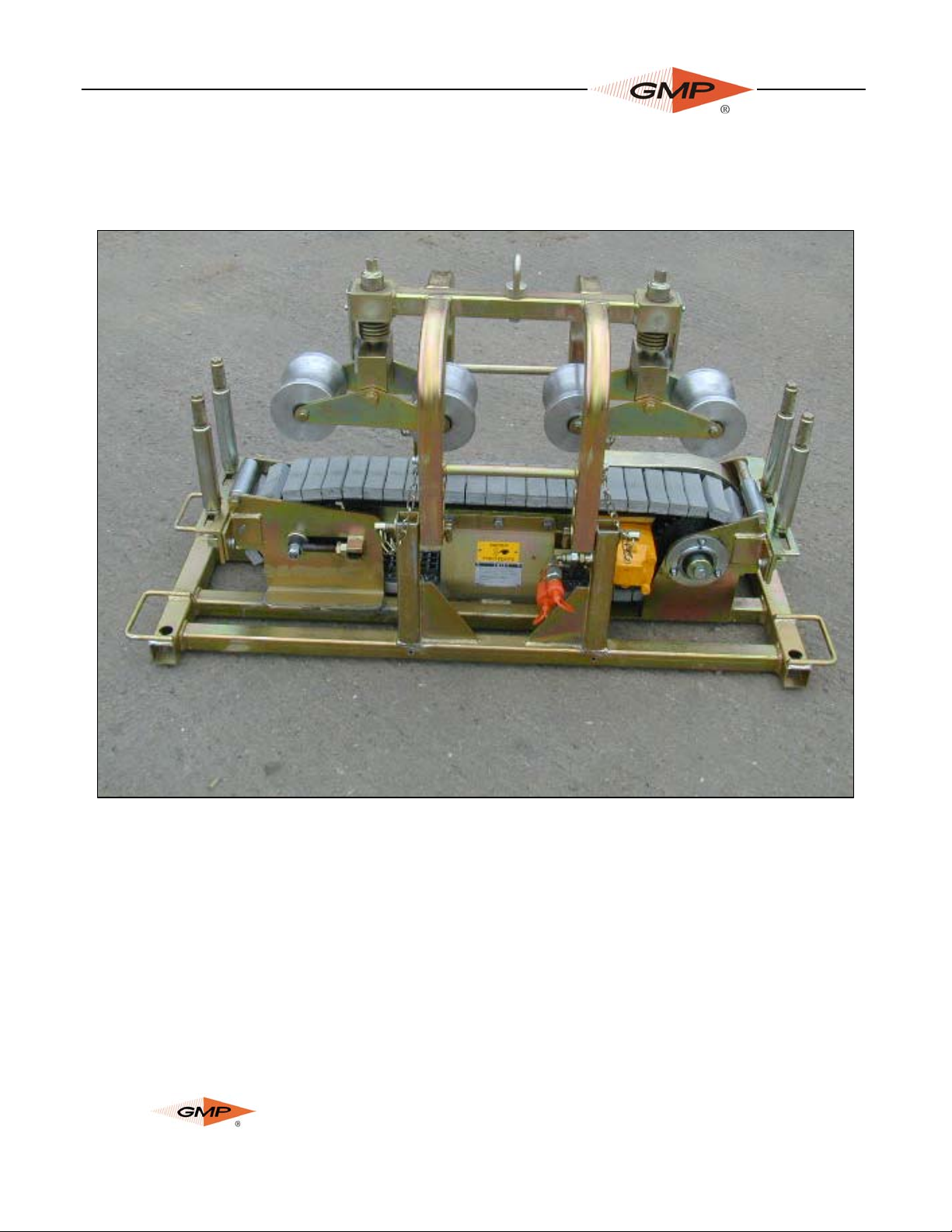
CABLE PUSHER
OPERA TION & MAINTENANCE MANUAL
Model 89760
Copyright 2012 by General Machine Products Co., Inc
All rights reserved. No part of this publication may be copied, reproduced or transmitted in any form whatsoever without
the written permission of
General Machine Products Co., Inc.
GMP • 3111 Old Lincoln Hwy • Trevose, PA 19053 • USA
TEL: +1-215-357-5500 • FAX: +1-215-357-6216 • www.gmptools.com
Page 1 of 25
General Machine Products Co., Inc.
July 2012 USA Ver 4
Manual P/N 34495
Page 2
REVISION HISTOR Y:
Rev
Date Details Author
No.
01 03-2003 Original issue M. Blasé
02 04-2006 Manual up-graded A Miller
03 01-2012 Responsible Person Updated L.Kilpin
04 07-2012 US Version A Konschak
Page 2 of 25
General Machine Products Co., Inc.
Page 3

CONTENTS
1.0 Introduction
2.0 Safety Instructions
3.0 General Description
4.0 Specification
5.0 Operating Procedure
6.0 Maintenance
7.0 Monthly Service – Check List
8.0 Service History Card
9.0 Equipment layout
10.0 Recommended Spares List
Page 3 of 25
General Machine Products Co., Inc.
Page 4
1.0 INTRODUCTION
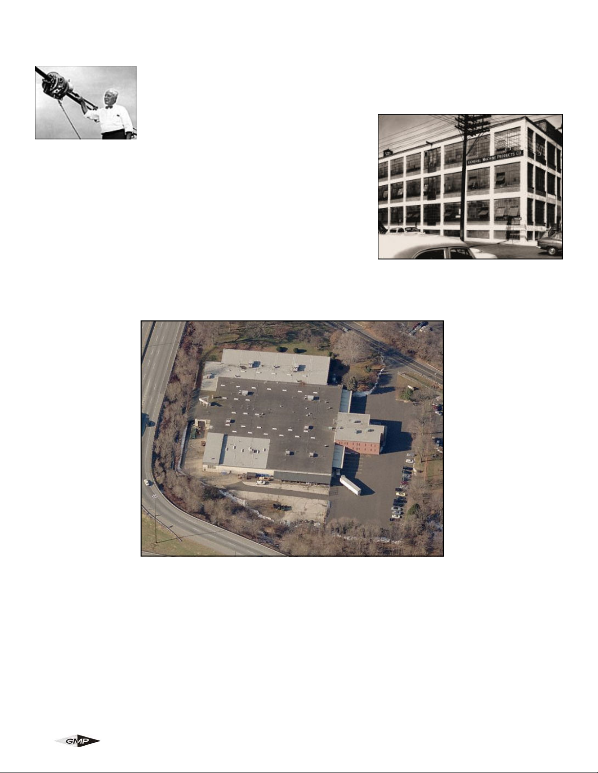
Founded by engineer George M. Pfundt in 1936, GMP started operations in a
downtown Philadelphia building as a specialty machine shop doing work for the
local Bell Telephone company and for the electric utility company. GMP expanded
to a production shop after landing a contract
with Western Electric Company and,
subsequently, forming a close relationship
with Bell Telephone Laboratories in Murray Hill, N.J., which enabled
it to manufacture prototypes of products for experimental use within
the Bell System.
Having outgrown the original factory building, the company built a
100,000 square foot plant in Trevose, PA (a Philadelphia suburb)
and moved there in 1957. Today GMP is recognized as a premier
worldwide supplier of specialty tools and equipment for the outside
plant marketplace. The company's products are known for their
robust design and durability to withstand many years of frequent use.
Page 4 of 25
General Machine Products Co., Inc.
Page 5

2.0 SAFETY INSTRUCTIONS
THIS EQUIPMENT MUST ONLY BE USED BY AUTHORIZED PERSONNEL, WHO
HAVE BEEN SUITABLY TRAINED AND COMPETENT TO DO SO.
THESE INSTRUCTIONS ARE T O BE MADE AV AILABLE T O OPERATORS OF THIS
EQUIPMENT A T ALL TIMES, F AILURE TO OBSERVE THESE SAFETY
INSTRUCTIONS COULD RESULT IN SERIOUS PERSONAL INJURY AND / OR
PROPERTY DAMAGE.
WORK AREA AND GENERAL SAFETY
1. Read and understand the operation and maintenance manual supplied with this equipment. Keep it in a
convenient place for future reference.
2. Keep children and untrained personnel away from this equipment while in operation.
3. Keep all guards and safety devices in place. Do not operate this equipment with guards removed or
damaged.
4. Keep hands and feet and loose clothing away from moving parts especially at cable entry point.
5. Always stop the machine and isolate the hydraulic services before carrying out lubrication and servicing.
6. Check machine before starting for worn or damaged parts. Check that all nuts and bolts are tight.
7. If machine is left unattended, ensure that unauthorised use is prevented.
8. Never leave the machine unattended while in use.
9. Consider the use of safety barriers, especially when used in public places.
10. Beware of pinch points involved with rotating components, e.g. screw operated tractor drive lifting
mechanisms.
11. Beware of hot surfaces, machine uses hydraulic services.
12. When operating the machine always wear eye protection, hard hat, safety shoes and leather gloves.
The machine operates with hydraulic oil at pressure of 60 bar.
13. Some competent and assembly parts are in excess of 55lbs. (25kg). When lifting care must be taken,
ensure sufficient man power/lifting gear is available, to prevent personal injury and damage to the
machine.
14. Prior to installation ensure the sub duct route (if applicable) is connected properly.
Page 5 of 25
General Machine Products Co., Inc.
Page 6

GENERAL HYDRAULIC SAFETY INSTRUCTIONS
Escaping fluids under pressure can penetrate the skin and cause serious personal injury. Observe the
following precautions to avoid hydraulic hazards:-
1. Tighten, secure all connections before applying pressure. Relieve pressure when connecting or
disconnecting hoses when servicing the unit.
2. Check for leaks with a piece of cardboard. Do not use your hands!
3. Do not exceed working pressure of hydraulic hoses.
4. Visually inspect hoses regularly and replace if damaged.
Page 6 of 25
General Machine Products Co., Inc.
Page 7
3.0 GENERAL DESCRIPTION
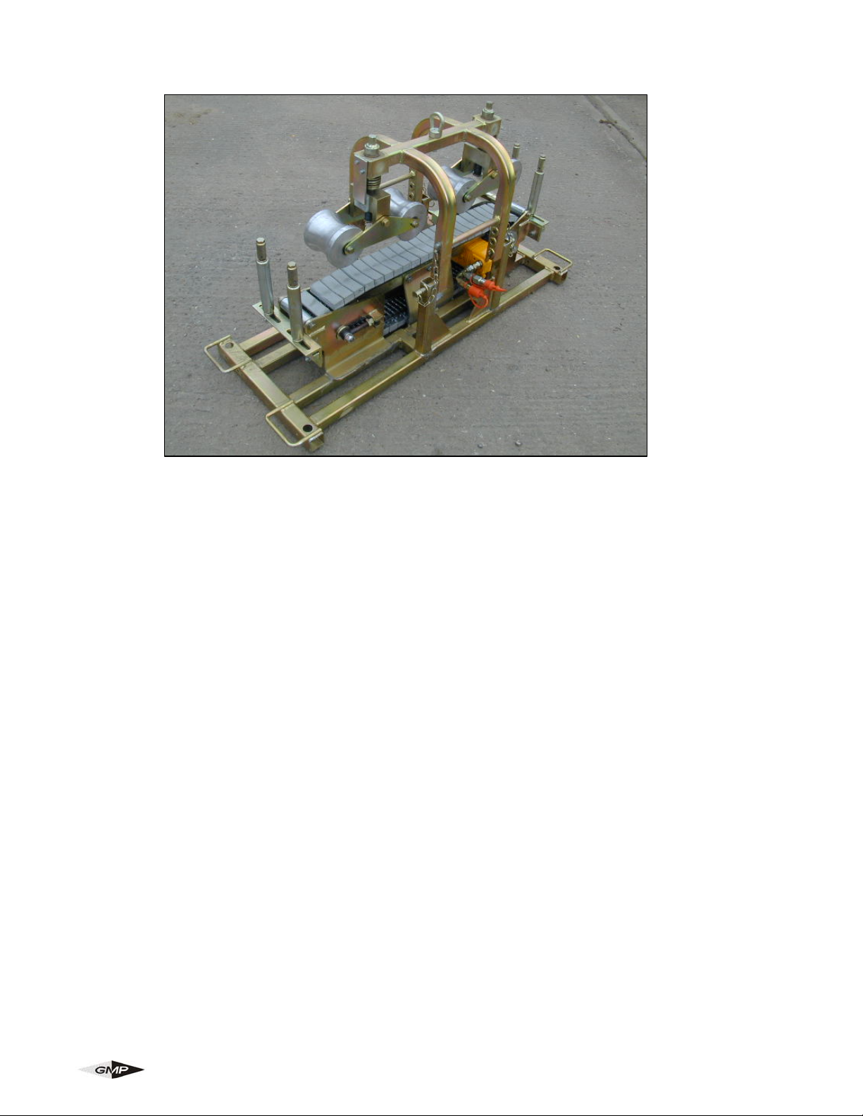
C-1350 CABLE PUSHER
The machine comprises of an hydraulically driven cable pusher unit designed to provide an effective and
safe method of installing 1 1/4 - 6” (30 –150mm) Dia. cable up to a speed of 33 ft/min (10 m/min).
The pusher unit is mounted on a sturdy anti corrosion treated tubular steel frame and is powered by a
hydraulic supply system operating from a recommended supply of 870 psi (60 bar) x 4.75 gpm (18 litres/
min).
The cable pusher is fitted with adjustable vertical rollers at each end to guide the cable through the
machine.
2 x hydraulic hoses x 23’ (7m) long can be supplied as an optional extra.
FEATURES
CABLE FEEDER
• Manufactured from fabricated and machined steel
• Hydraulically powered
• Unit lifts and splits to allow insertion of cable between drive chain and roller.
• Drive chain has, optimised profile and moulded to chain drive unit ensuring long life between
replacement..
• Belt tension can be set by means of adjustable chain drive tensioner fitted to side of unit.
CHASSIS
• Lightweight anti corrosion painted tubular steel frame
• Hydraulic control lever mounted on handle
• Quick release hydraulic hose couplings
Page 7 of 25
General Machine Products Co., Inc.
Page 8

4.0 SPECIFICATION
Serial No:
OPERATING CAPACITIES
Pushing Force: 1100 - 1540 lbs. (500 - 700 kg) at 870 psi. (60 bar)
Pushing Speed: 0 - 33 ft./ min (0 – 10 m/min)
Minimum cable diameter 1 1/4” (30 mm)
Maximum cable diameter 6” (150 mm)
HYDRAULIC DRIVE SYSTEM
Operating Pressure: 870 psi. (60 bar)
Flow: 4.75 gpm (18 Litres/min) (recommended)
Relief Valve Setting: 870 psi. (60 bar)
DIMENSIONS AND WEIGHTS
Height: 30.3” (740 mm)
Length: 54.7” (1390 mm)
Width: 19.7” (500 mm)
Weight: 440 lbs. (200 kg)
Drive Chain Lubrication: Metaflux 70-07 Grease Spray
Page 8 of 25
General Machine Products Co., Inc.
Page 9

5.0 OPERATING PROCEDURE
IT IS IMPERATIVE THAT ALL PERSONS USING, OPERATING OR MAINTAINING THIS
WINCH BE FULLY TRAINED AND COMPETENT TO DO SO, AND HAVE READ THE
ENTIRE OPERATING MANUAL.
GENERAL MACHINE PRODUCTS CANNOT BE HELD RESPONSIBLE FOR MIS-USE
OF THIS EQUIPMENT.
• Position the cable pusher at the desired angle for entry into the joint box, ideally this should be on
firm level ground.
• Ensure that the cable pusher is adequately anchored down / restrained.
• Raise the upper roller assembly by removing 2 retaining pins from one side and pivot roller
assembly out of the way.
• For large diameter cables it may be advantageous to remove 2 vertical end rollers from the same
side as of the machine as the removed retaining pins.
• Cable can now be laid onto drive chain.
• Replace vertical end rollers, (if removed to allow easy access to insert the cable) and adjust to give a
5mm clearance each side of the cable.
• Ensure the upper rollers are positioned at the top position of their travel.
• Pivot the upper roller assembly back to the operating position, ensure that the best hole position to
suit the size of the cable is selected and refit the 2 retaining pins.
• Lower the two sets of rollers in conjunction by tightening the main jacking screws until contact
is made with the cable, then turn the jacking screw a further 1½ turns.
• Connect the hydraulic hoses from the hydraulic power pack and suitable control valve via the quick
release couplings..
• Start the power pack and operate the hydraulic control lever to commence the cable feed
operation, NOTE the power pack operator must be competent and fully trained in the use of
the power pack.
Page 9 of 25
General Machine Products Co., Inc.
Page 10

6.0 MAINTENANCE
To ensure reliable service from the Cable Pusher, GMP recommends the unit to be completely serviced at
6 monthly intervals.
TRACTOR DRIVE
Inspect the chain drive blocks for wear. Clean all drive blocks after each operation or as required. (it may
be necessary to remove the upper roller frame assembly to clean thoroughly). Check the chain tension
weekly and adjust if necessary with the two external adjustment screws. (Do not over tension – the chain
should just slightly lift of the chain guides when pulled at the centre by finger).
GENERAL
The machine should be wiped clean after use and stored under cover.
Oil the frame pivot points monthly and apply grease to the jacking screw thread. After each use clean off
any dirt/debris from the cable guide rollers and upper frame rollers.
The chain should be lubricated every week by application of Metaflux Spray Grease 70-07. This is achieved
by running the unit (without any cable.
Do not over lubricate as this may lead to contamination of the drive belts. Should contamination of the belts
occur, wipe the belts thoroughly clean before attempting any cable pushing operation.
Check the condition of the hydraulic hoses each time and replace if worn or damaged.
6.1 MAINTENANCE SCHEDULE
PROCEDURE DAILY WEEKLY MONTHLY
Clean all assemblies and components thoroughly
Inspect hydraulic hoses for leaks and cracks
Inspect fasteners, screws and retaining pins/wires
Check/Adjust chain tension
Check tractor drive pads for wear/damage
Clean cable entry bracket
il the frame pivot points
Grease jacking screw thread
Oil oilite bearings with light machine oil
Lubricate drive chain*
• Should be more often if subjected to enable normal use and/or excessive contamination.
Page 10 of 25
General Machine Products Co., Inc.
Page 11

7.0 MONTHLY SERVICE – CHECK LIST
• Check the chain for excessive wear. Replace, if required – and lubricate with the spray grease
provided.
• Remove any debris / dirt from the drive belts, upper frame rollers and cable guide rollers.
• Check the chain support pad for excessive wear, replace if required.
• Check all other moving parts e.g. bearings, shafts, sprockets etc – and lubricate.
• Check main jacking screws – and lubricate.
• Check all hydraulic fittings for leaks.
• Check the hydraulic hoses for external damage.
• Check entry /exit guide rollers and upper frame rollers for excessive wear.
Page 11 of 25
General Machine Products Co., Inc.
Page 12

8.0 SERVICE HISTOR Y RECORD
Service No Date Record of Repair Carried out by
Page 12 of 25
General Machine Products Co., Inc.
Page 13
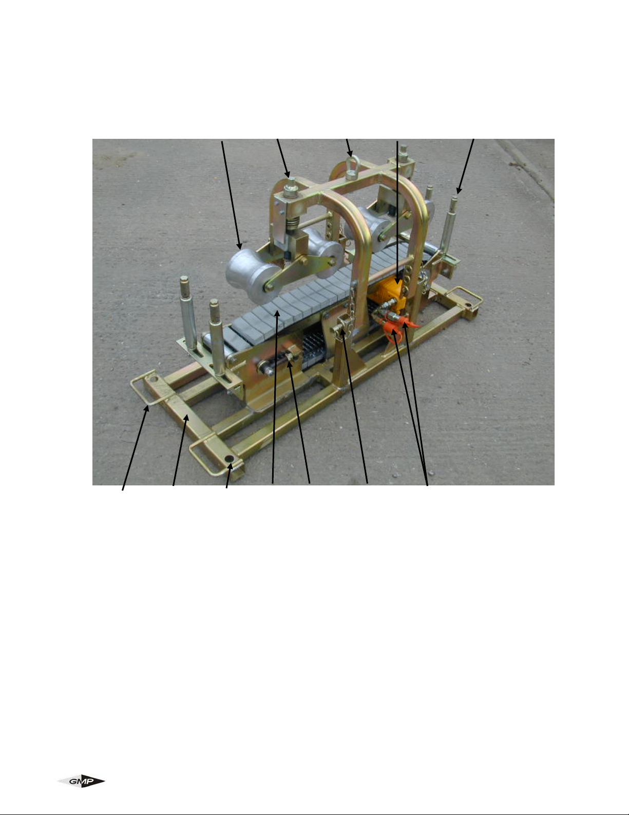
9.0 EQUIPMENT LAYOUT
4 5 7 9 3
6 1 8 2 12 11 10
1 BASE FRAME
2 DRIVE BELT
3 VERTICAL END ROLLER (CABLE GUIDE)
4 UPPER ROLLER ASSEMBLY
5 UPPER ROLLER ADJUSTING SCREW
6 LIFTING HANDLE
7 UNIT LIFTING EYE BOLT
8 GROUND ANCHOR / CABLE PUSHER RESTRAINING HOLE
9 HYDRAULIC MOTOR
10 HYDRAULIC HOSE CONNECTIONS
11 UPPER ROLLER FRAME RETAINING PIN
12 DRIVE CHAIN ADJUSTING NUT
Page 13 of 25
General Machine Products Co., Inc.
Page 14

10.0 RECOMMENDED SPARES LIST
For spare parts always quote the model type serial number and contact:-
General Machine Products Co., Inc.
3111 Old Lincoln Hwy
Trevose, PA 19053 • USA
TEL: +1-215-357-5500 • F AX: +1-215-357-6216 • EMAIL: [email protected]
TYPICAL SPARES:
Part No. Description Qty Required
34496 Chain 3/4” Triplex 1
89153 Metaflux Chain Spray 70-88 1
Please give as much information as possible to ensure correct identification and supply of spare parts.
Page 14 of 25
General Machine Products Co., Inc.
Page 15

Page 15 of 25
General Machine Products Co., Inc.
Page 16

GMP • 3111 Old Lincoln Hwy • Trevose, PA 19053 • USA
TEL: +1-215-357-5500 • FAX: +1-215-357-6216 • EMAIL: [email protected]
Page 16 of 25
General Machine Products Co., Inc.
 Loading...