

Page 1
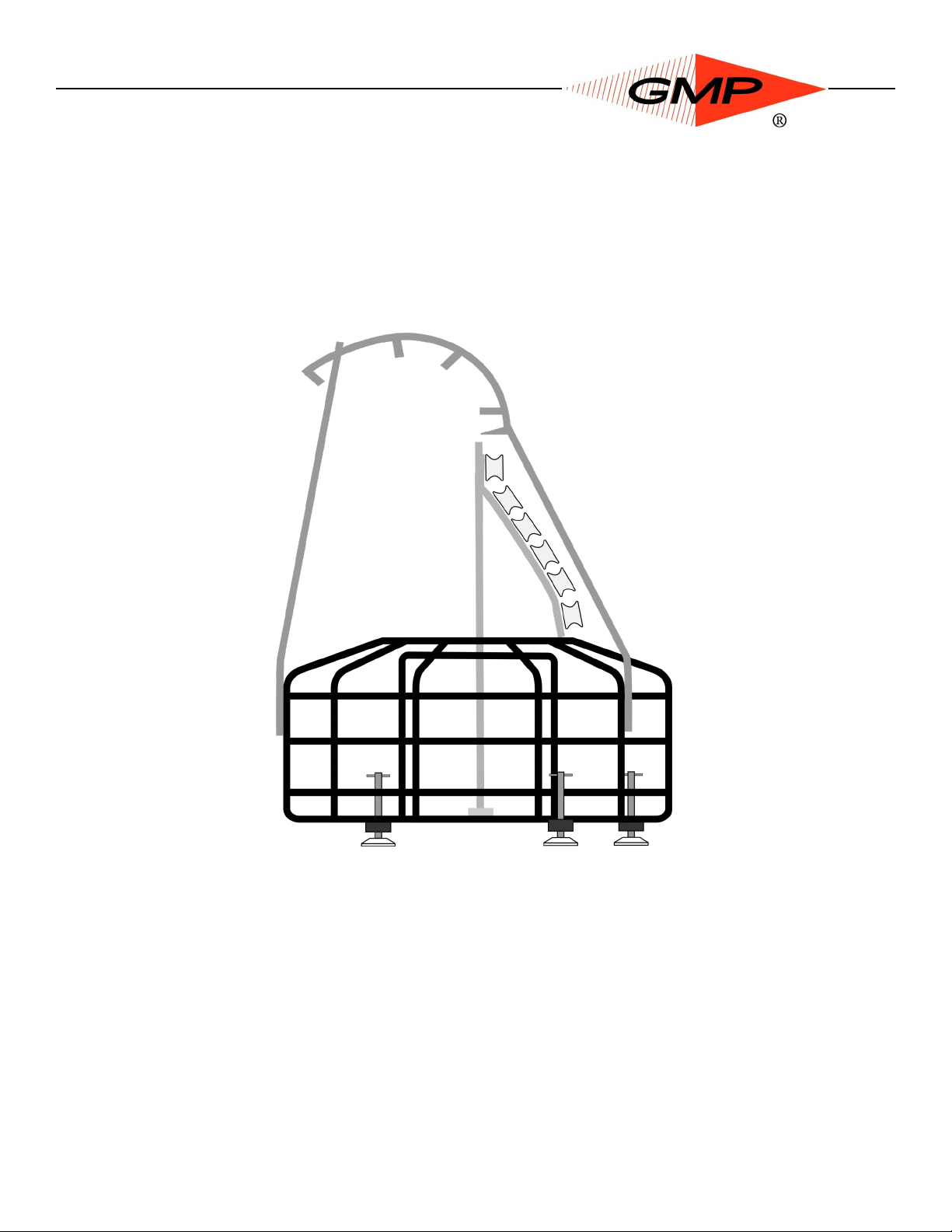
M ICRO CABLE FLEETER
Operation and Maintenance
Model 89002
All rights reserved. No part of this publication may be copied, reproduced or transmitted in any form whatsoever without the written permission of General Machine Products Co., Inc.
General Machine Products Co., Inc. • 3111 Old Lincoln Hwy • Trevose, PA 19053 • USA
TEL: +1-215-357-5500 • FAX: +1-215-357-6216 • EMAIL: [email protected]
P/N 30180 Ver2
Page 1 of 14
AK 08/28/13
Page 2

REVISION HISTORY:
Rev
No.
Date Details Author
01 11-2007 Original issue A. Miller
02 6-2011 US Version A. Konschak
Page 2 of 14
Page 3

CONTENTS
1.0 Introduction and Safety Instructions
2.0 General Description
3.0 Specification
4.0 Cable Threading and Operating Procedure
5.0 Equipment Layout
6.0 Spare Parts
7.0 Maintenance
Page 3 of 14
Page 4

1.0 SAFETY INSTRUCTIONS
THIS EQUIPMENT MUST ONLY BE USED BY AUTHORIZED
PERSONNEL, WHO HAVE BEEN SUITABLY TRAINED AND
COMPETENT TO DO SO
THESE INSTRUCTIONS ARE TO BE MADE AVAILABLE TO
OPERATORS OF THIS EQUIPMENT AT ALL TIMES.
1. Read and understand the operation and maintenance manual
supplied with this equipment. Keep it in a convenient place for future
reference.
2. Keep children and untrained personnel away from this equipment
while in operation.
3. Keep all guards and safety devices in place. Do not operate this
equipment with guards removed or damaged.
4. Keep hands, feet and loose clothing away from moving parts.
5. Always stop the machine to carry out lubrication servicing.
6. Check machine before starting for worn or damaged parts. Check that
all nuts and bolts are tight.
7. If machine is left unattended, ensure that unauthorized use is
prevented.
8. Never leave the machine unattended while in use.
9. Consider the use of safety barriers, especially when used in public
places.
10. Beware of pinch points involved with rotating components, e.g.
rope/cable drums, capstans, bull wheels, shafts and chain drives.
11. Some component and assembly parts are in excess of 70lb (32kg).
When lifting care must be taken, ensure sufficient man power/lifting gear is available, to
prevent personal injury and damage to the machine.
Page 4 of 14
Page 5
INTRODUCTION
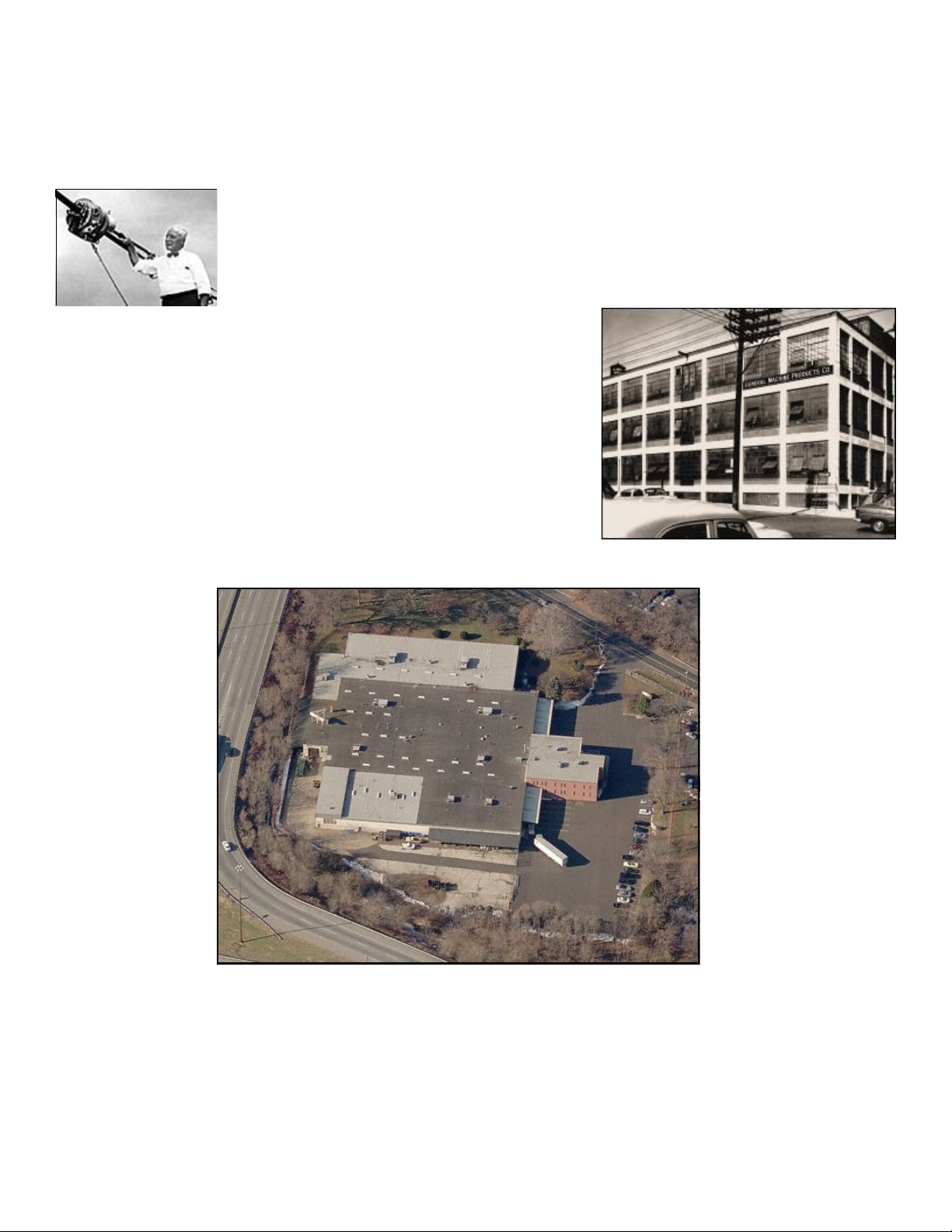
Founded by engineer George M. Pfundt in 1936, GMP started operations in a downtown Philadelphia building as a specialty machine shop doing work for the local Bell
Telephone company and for the electric utility company. GMP expanded to a produc-
tion shop after landing a contract with Western Electric Company
and, subsequently, forming a close relationship with Bell Telephone
Laboratories in Murray Hill, N.J., which enabled it to manufacture
prototypes of products for experimental use within the Bell System.
Having outgrown the original factory building, the company built a 100,000 square foot plant in Trevose, PA
(a Philadelphia suburb) and moved there in 1957. Today GMP is recognized as a premier worldwide supplier of specialty tools and equipment for the outside
plant marketplace. The company's products are known
for their robust design and durability to withstand many
years of frequent use.
Page 5 of 14
Page 6

2.0 General Description
The Micro Cable Fleeting Device has been developed to enable longer lengths of fiber optic cable to be deployed from a single drum.
With the increasing trend of longer cable installations with more efficient cable blowing
techniques there is a need for a Micro Cable Fleeting device.
The need arises following the initial installation of the first half of the fibre optic cable
from the drum.
The balance of the cable on the drum needs to be removed, stored safely, with the inner end of the cable ready to be placed in the cable duct. See section 4.0.
The traditional method to achieve this operation is to employ manual labor to rotate
the drum while members of the team form the cable being removed into a figure 8
configuration on the ground.
By using the Micro Cable Fleeter this operation can be achieved in less time with less
manual labor and with the cable safely stored in the cassette ensuring that the cable
will not be damaged by passing vehicles or pedestrians.
The fleeter has been designed to Fleet micro cable safely without over tensioning, excessive bending or kinking of the cable.
It has a nominal capacity to store 6500 ft. (2000 meters) of 8.5mm diameter cable.
“WARNING”
The principle of operation and storage rate has been designed for major cable types.
However, account should be made for miscellaneous cables, which have characteristics that do not always meet this standard. This may affect the volume of cable stored
or the machine may have to be run at lower speeds. This could be curved cables, extremely soft cables or none symmetrical cables. The operator must establish the correct speed of operation and loading for the cable types being employed.
It is recommended that this should be assessed by trial on your particular cable prior
to site operation.
Page 6 of 14
Page 7

3.0 Specification
Cable diameter
Max Cable Length
Dimensions
Basket Diameter
Max. Width
Height
Weight
5 – 8.5 mm (0.196” –0.334”) OD
6500 Feet (2000 Meters )
47.25” (1200 mm)
50.6” (1825 mm)
55.9” (1420 mm)
99 lb (45 kg )
Page 7 of 14
Page 8
4.0 Cable Threading and Operating Procedure
IT IS IMPERATIVE THAT ALL PERSONS USING, OPERATING OR MAINTAINING
THIS DEVICE BE FULLY TRAINED AND COMPETENT TO DO SO, AND HAVE
READ THE ENTIRE OPERATING MANUAL.
GMP CANNOT BE HELD RESPONSIBLE FOR MISUSE OF THIS EQUIPMENT.
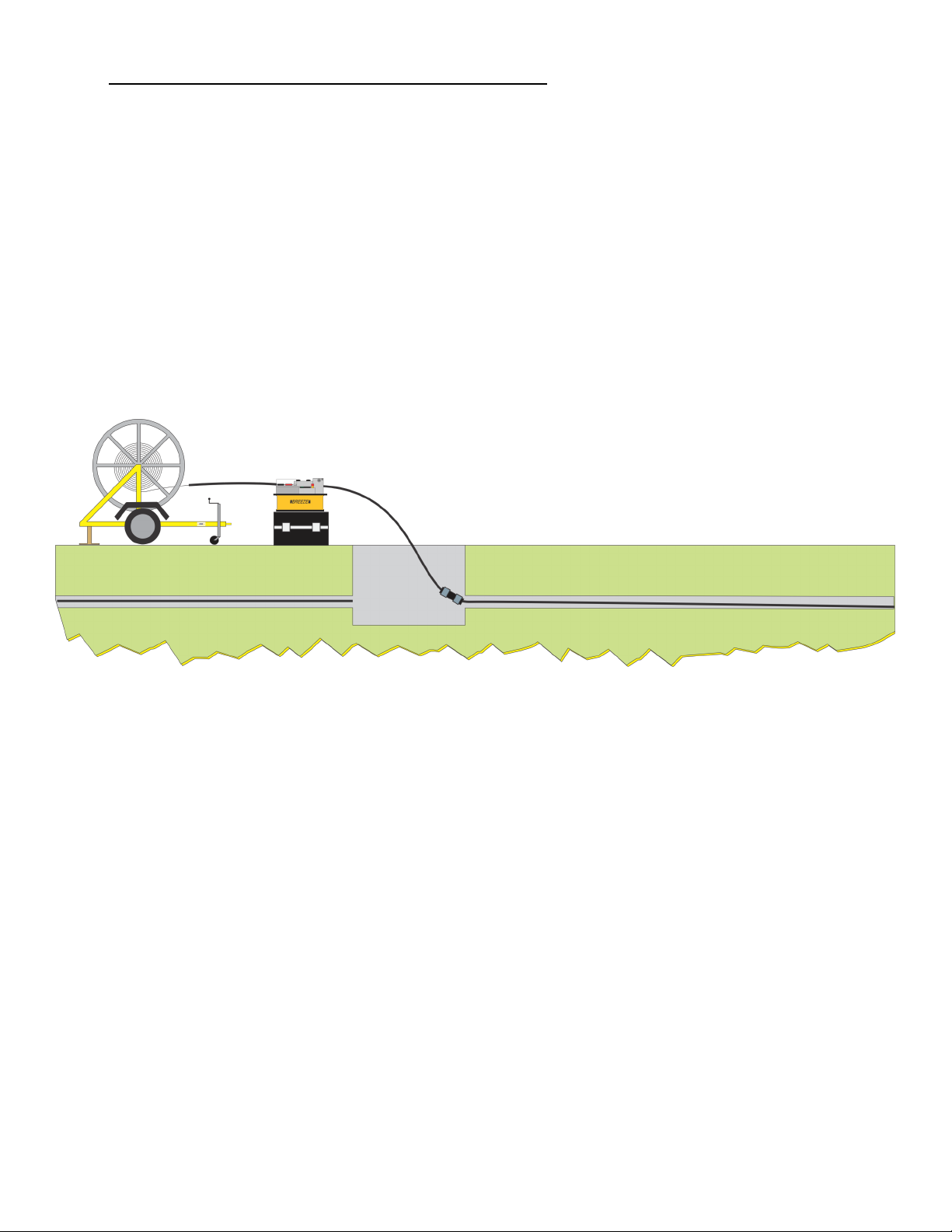
4.1 The first stage of the mid span installation should be to add 15’ (5m) length of tube
and connector between the blowing unit and the innerduct placed in the ground. (A
suitable slave length of tube may at this stage be placed between the cable drum and
the cable blower for use in installing the second length of cable). Installation should
then be completed as per diagram (Figure 1). i.e. cable blown through first duct with
cable for the second duct still on the drum.
Figure 1
4.2 The Cable Fleeter should be positioned adjacent next to the manhole and levelled
up by adjusting the feet until level. A level indicator is attached to the cable fleeter
frame. Note: The innerduct connected to the blower should be disconnected at the
manhole duct with sufficient cable being left between the manhole and the fleeting device to allow for any subsequent repositioning of the fleeting device when loaded with
cable.
The GMP Breeze cable blower machine should be positioned in line with the tube clamp
brackets on the fleeter.
The drum trailer or drum stand should be positioned approximately 15’ (5m) from the
cable blower, directly in line with the blower and the fleeter unit see (Figure 2).
Page 8 of 14
Page 9
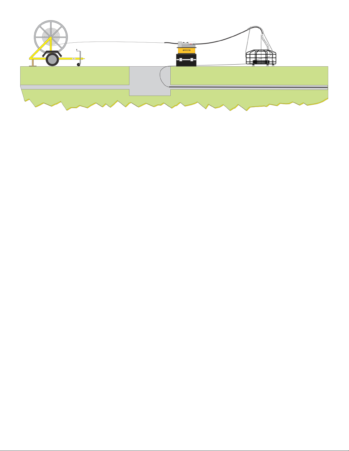
Figure 2
Undo the tube clamp and tube guide brackets in the fixed quadrant and unscrew and
retract the adjustable rollers on the rotating carousel.
Pull a suitable length of cable from the drum and through the 15’ piece of innerduct
and insert the loop through the gap in the fleeter and clockwise around the central
frame of the cable storage basket. See Fig 2.
Clamp the innerduct, into tube clamp on the fixed quadrant. The tube can protrude
through the clamp to within 1 to 1-1/2” (30-40 mm) of the rollers. Note: The correct
size of clamp collets to suit the tube need to be fitted to the tube clamp. Various sizes
are available, They must be made available for use prior to commencement of the installation. The tube needs to be located in the tube guides mounted on the fixed
quadrant, unscrew the wing nut and slide the retaining plate out of the way, the tube is
located in the guide bracket, the retaining plate is moved back into position and held
in position by tightening the wing nut.
Adjust each cable guide roller in turn on the rotating quadrant ensuring the cable is located into the vee of the rollers. Ensure that each roller rotates when the securing
wing nut is tightened, there should be a gap of approximately 1/32” (1 mm) between
the rollers.
Note: Both rollers on the second set of guide rollers down from the top of the rotating
carousel are adjustable, they need to be set up to suit the diameter and bending radius of the cable, ensure that when set there is a gap of 1/32” (1 mm) between the rollers, this will allow the rollers to rotate.
4.3 When the cable has been placed in the fleeter an end will be available as per
(Figure 3), remove the 15’ piece of innerduct from blower and replace with a short
length of innerduct, to protect the cable before installation into the second duct. (Note
the slave tube attached to the cable at 4.1 may be used). The cable may now be
blown into the second duct using the correct equipment to prevent over tensioning
and sharp bending of the cable to complete the installation through the two ducts as
per (Figure 4).
Page 9 of 14
Page 10
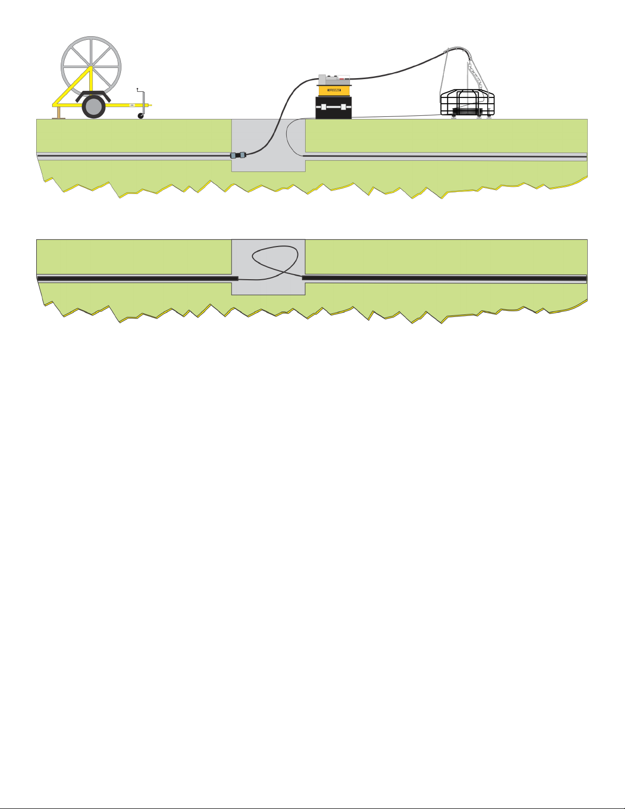
Figure 3
Figure 4
Page 10 of 14
Page 11
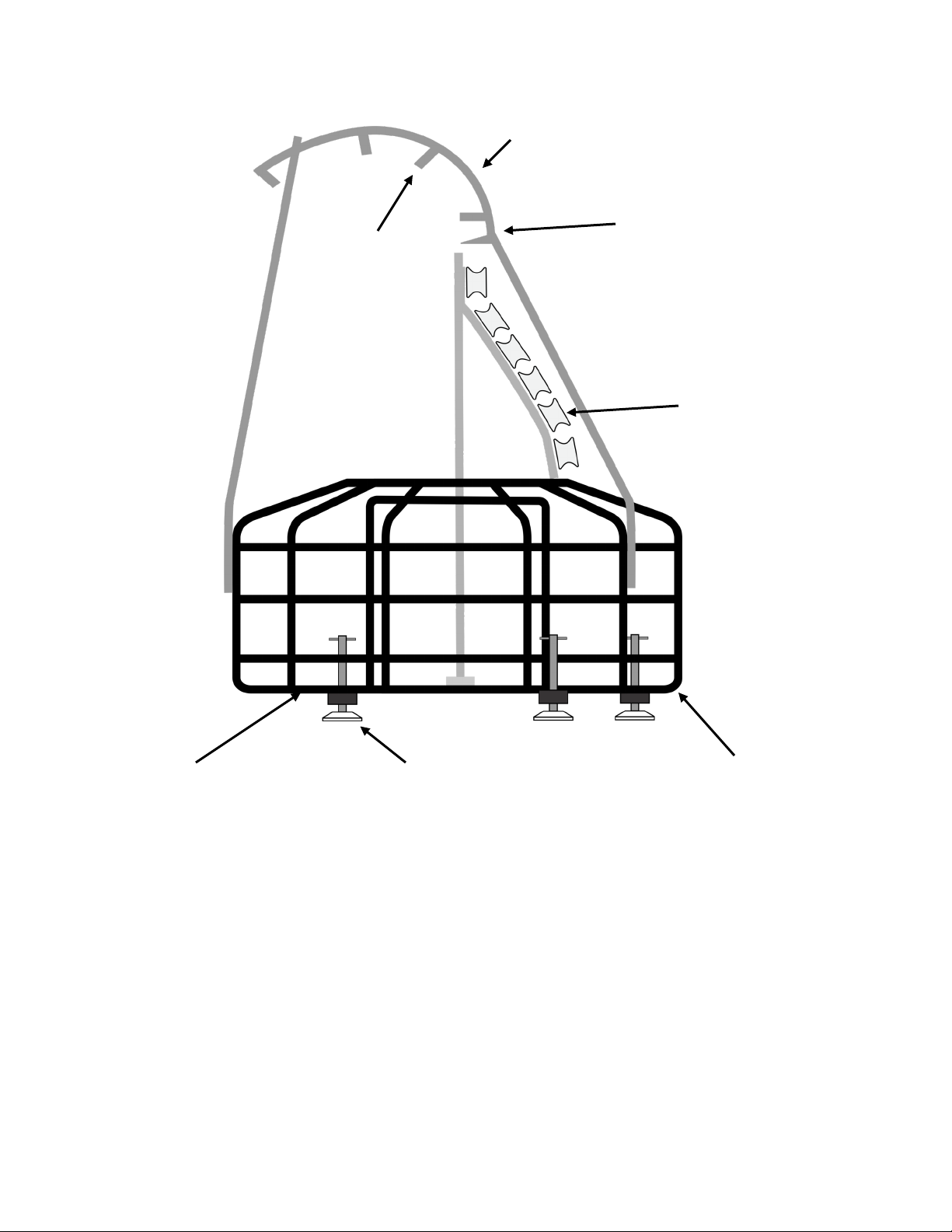
5.0 Equipment Layout
2
6
7
3
4 5
1 Cable storage cassette
2 Fixed quadrant
3 Rotating cable guide carousel
4 Levelling foot
5 Level indicator device
6 Tube clamp
7 Tube guide clamp
Page 11 of 14
1
Page 12

6.0 Spare Parts
For spare parts contact:
General Machine Products Co., Inc.
3111 Old Lincoln Hwy
Trevose, PA 19053
Telephone No: 215-357-5500
Facsimile No: 215-357-6216
E-mail: [email protected]
Model: 89002 Fleeting Device
Page 12 of 14
Page 13

Page 13 of 14
Page 14

GMP • 3111 Old Lincoln Hwy • Trevose, PA 19053 • USA
TEL: +1-215-357-5500 • FAX: +1-215-357-6216 • EMAIL: [email protected]
Page 14 of 14
 Loading...