

Page 1
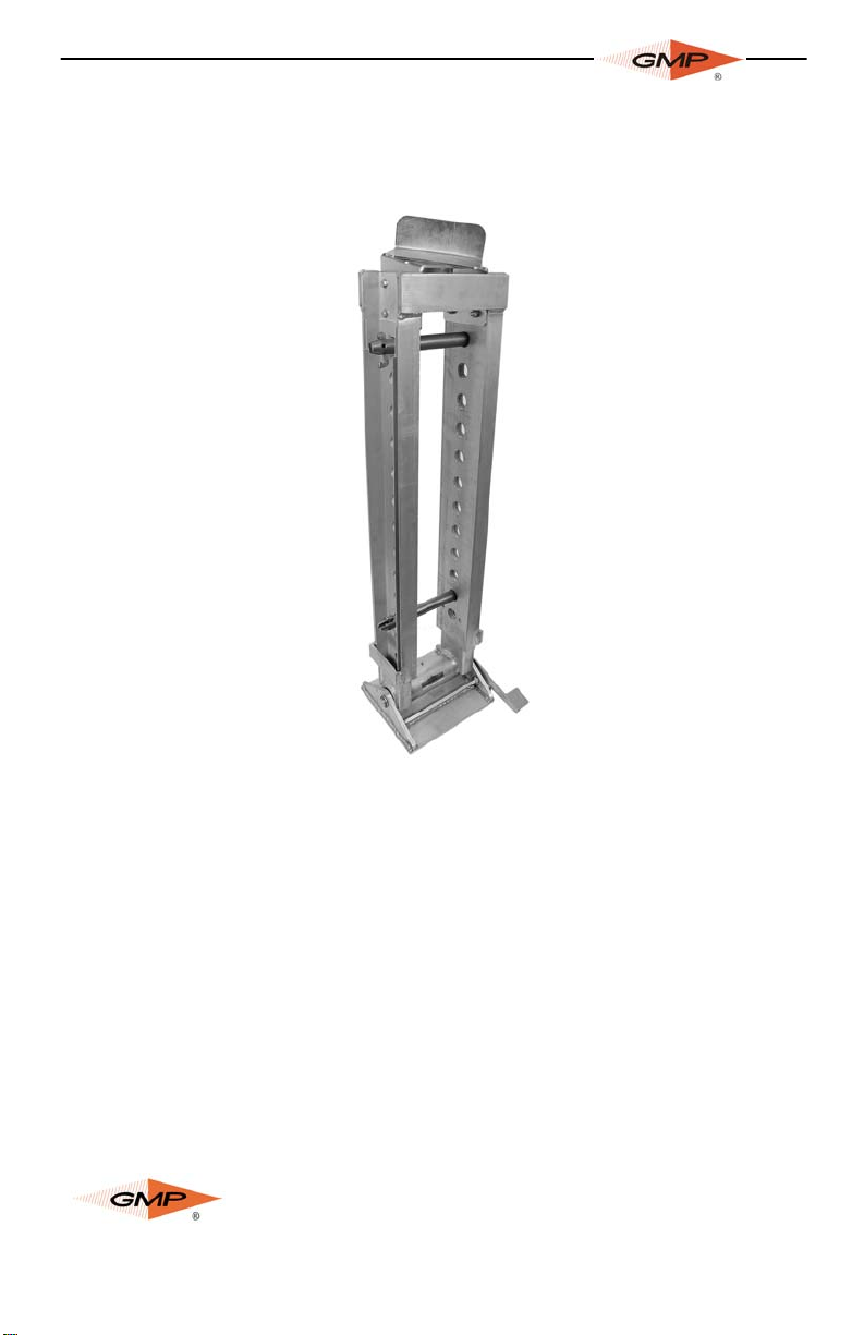
JAMB SKID
OPERATION & MAINTENANCE MANUAL
P/N RANGE
70640 48” to 85”
70643 84” to 121”
70646 114” to 151”
Copyright 2012 by General Machine Products Co., Inc
All rights reserved. No part of this publication may be copied,
reproduced or transmitted in any form whatsoever without the
written permission of
GMP • 3111 Old Lincoln Hwy • Trevose, PA 19053 • USA
General Machine Products Co., Inc.
TEL: +1-215-357-5500 • www.gmptools.com
June 13 2012 USA Ver 1
Page 1 of 4
General Machine Products Co., Inc. www.gmptools.com
Manual P/N 34654
Page 2
INSTALLATION
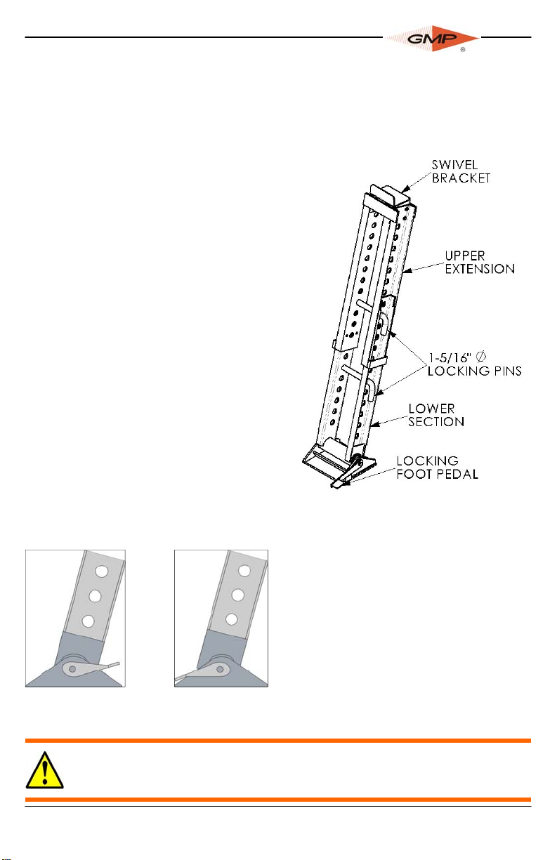
1. Lower the lower section of the Jam Skid into the manhole.
Rotate the locking foot pedal to the unlocked position
(figure A).
2. Align the center of the jam skid with the
center of the duct.
3. Lower the upper section into the manhole and install the upper section into
the lower section.
4. Raise the upper section so the swivel
bracket rests under the lip of the
manhole and the entire jam skid
rests at an angle of approximately
75° from the floor.
5. Install a locking pin to secure the 2
sections.
6. Using the 2nd locking pin install a
sheave or quadrant of suitable
size for the cable between the
jam skid legs and align with the
duct.
7. Secure the jam skid by moving the
base in or out slightly while pressing down on the locking foot
pedal until the locking foot pedal fully engages (B).
REMOVAL
A
unlocked
This equipment should be used only by personnel who have been given the appropriate training
and who are competent to use it.
These instructions are to be made available to operators of this equipment at all times. Failure to
observe these safety instructions could result in serious personal injury and/or property damage.
www.gmptools.com
B
fully engaged
and locked
1. Place leverage bar under
locking foot pedal and pry up
to release the Jamb Skid.
2. Remove the Jamb Skid by
reversing the installation procedure.
Page 2 of 4
General Machine Products Co., Inc.
Page 3
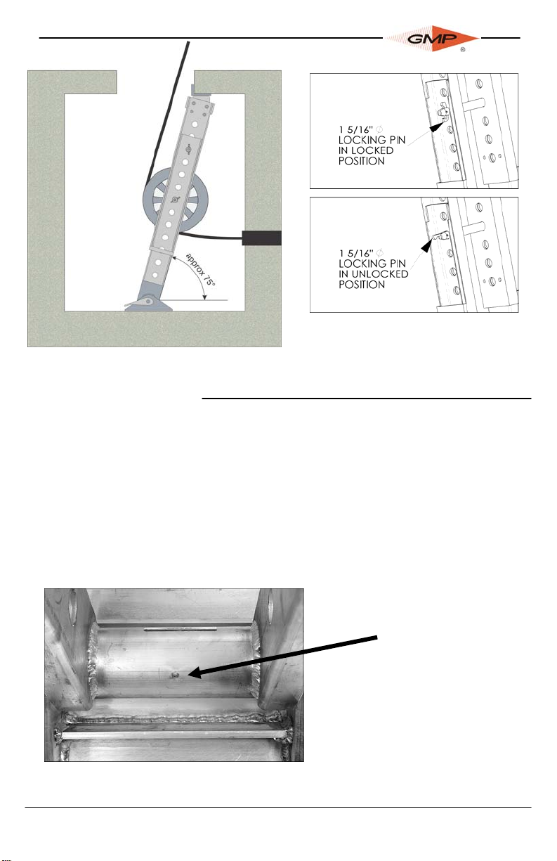
70640 & 70643 rated @ 10,000 lbs.
70646 rated @ 5,000 lbs.
Maintenance
1. Before use, ensure that the Jam Skid is not damaged, bent or
twisted and all bolts are tight
2. Locking pins should be wiped with a light oil to prevent rust.
3. Jam skid should be cleaned of all mud and contaminates before storage.
4. Locking foot should be periodically greased to ensure smooth
operation.
Grease Fitting
Page 3 of 4
General Machine Products Co., Inc. www.gmptools.com
Page 4

OPTIONS
Quadrant Blocks
P/N Max. Cable Size Weight
84453
84454
84455
Cable Sheaves
P/N WIDTH DIAMETER ROOT Weight
71723
71726
71729
71722
71725
71728
71721
71724
71727
3 in. (8 cm) 11 in.(28 cm) 8-1/2 in.(22 cm) 15 lbs.(7 kgs)
4 in.(10 cm) 11 in.(28 cm) 7-7/8 in.(20 cm) 20 lbs.(9 kgs)
5 in.(13 cm) 11 in.(28 cm) 6-7/8 in.(17 cm) 25 lbs.(11 kgs)
3 in.(8 cm) 20 in.(51 cm) 17-1/2 in.(44 cm) 32 lbs.(15 kgs)
4 in.(10 cm) 20 in.(51 cm) 16 in.(41 cm) 36 lbs.(16 kgs)
5 in.(13 cm) 20 in.(51 cm) 16-1/2 in.(42 cm) 40 lbs.(18 kgs)
3 in.(8 cm) 26-1/2 in.(67 cm) 24 in.(61 cm) 38 lbs.(17 kgs)
4 in.(10 cm) 26-1/2 in.(67 cm) 22-1/2 in.(57 cm) 44 lbs.(19 kgs)
5 in.(13 cm) 26-1/2 in.(67 cm) 23 in.(58 cm) 56 lbs.(25 kgs)
Extensions – Note: only one extension can be used at a time. Do not stack
P/N Description
31356
31357
31358
Optional extension that allows the user to convert the height of the 70643 or
70646 to 48 in. to 85 in. (121.9 to 215.9 cm). Rated at 10,000 lbs. cable tension.
Optional extension that allows the user to convert the height of the 70640 or
70646 to 84 to 121 in. (213.4 to 307.3 cm). Rated at 10,000 lbs. cable tension.
Optional extension that allows the user to convert the height of the 70640 or
70643 to 114 to 151 in. (289.6 to 383.5 cm). Rated at 5,000 lbs. cable tension.
3 in. (76 mm) 60 lbs (27 kgs)
4 in. (102 mm) 75 lbs (34 kgs)
5 in. (127 mm) 90 lbs (40 kgs)
www.gmptools.com
Page 4 of 4
General Machine Products Co., Inc.
 Loading...