

Page 1

General Machine Products Co.
3111 Old Lincoln Highway
Tel:
Fax: +1.215.357.6216
Email: [email protected]
Web: www.GMPtools.com
+1.215.357.5500
· Trevose, PA 19053-4996 USA
Page 2

Installation, Operation and Maintenance Manual for
the Adams® Model CD Lite Continuous Duty Winch
manufactured by General Machine Products Co., Inc.
Scope
This document contains information pertinent to the Installation, Operation and Maintenance of the Adams® model CD Lite - Continuous Duty Winch. Such winches as manufactured by General Machine
Products Co., Inc. commencing in June 1, 1995 were significantly different from the larger Adams model
CD Winches in their equipment design and components. To obtain information on heavy duty models
CD, LCD or UG winches, please contact the factory for the appropriate manual.
Section Contents Page
1 General Information 1
2 Precautions 4
3 Installation 6
4 Pre-operational Checks 16
5 Operating Instructions 17
6 Maintenance 18
7 Replacement Parts 20
1.01 GENERAL - The information contained in this revision pertains exclusively to the Adams®
Model CD Lite Continuous Duty Winches manufactured after June 1, 1995 which have serial numbers
of 95-8000 and higher.
The CD Lite winch has been specifically designed for placing innerduct, fiber optic, coaxial and other
types of communications media where typical pulling forces are not expected to exceed 2000 lbs. (8.9
kN). However, its robust construction and SAE Continuous Duty rating makes the CD Lite suitable for
most applications where a long, continuous pull is required. In its typical automotive application the
winch is driven hydraulically - for mobile mounting, using the truck engine as the prime source of
power, through a split shaft or side mount power take-off, coupled to a hydraulic pump, driving a hydraulic motor that is mounted to the full load brake, which is assembled directly onto the gearbox.
1.02 WINCH MAJOR COMPONENTS
• Gearbox
• Wire Rope Drum
• Drum Guard
• Clutch Assembly
• Free Spool Control Brake
• Level Wind Assembly
• Full Load Brake
• Hydraulic Motor
• Hanger
• Mounting Brackets
• Drum Shaft Extension (available option)
Page 1
Page 3

1.03 WINCH CLUTCH GENERAL INFORMATION
The clutch provides a means of transferring the torque from the drum shaft to the winch drum. When
the winch clutch is disengaged, the drum will rotate freely on the drum shaft. Power can still be transmitted through the drum shaft to the optional drum shaft extension to drive a capstan or reel, if so
equipped, while the clutch is disengaged. An air shift mechanism actuates the clutch plate in and out.
To help ascertain clutch engagement or disengagement, clutch position sensing is a standard feature.
The clutch plate position is sensed at the end of the stroke of the air cylinder actuating the clutch plate.
1.04 CALIPER TYPE, FREE SPOOL CONTROL (DRAG) BRAKE
Under rapid winch line payout conditions, it is extremely important to operate the caliper brake properly, maintaining sufficient tension on the wire rope. This will enable the level-wind assembly to operate properly, minimize over-spinning of the drum, and help to prevent erratic lays of winch line on the
drum.
All CD Lite units are factory equipped with a caliper type drag brake assembly. The caliper brake is
controlled by a hydraulic actuator (supplied), and is intended to be mounted with the winch controls.
The purpose of the caliper brake is to control the speed of the winch drum when in the free spool mode.
Movement of the actuator lever will force the brake pads together, reducing the drum speed. Continued
movement of the control lever will eventually force drum rotation to stop.
CAUTION! THE DRAG BRAKE IS USED TO CONTROL THE DRUM SPEED ONLY. IT IS NEVER
TO BE USED TO HOLD THE LOAD.
The brake assembly is mounted at the factory onto a bracket attached to the hanger on the right side of
the winch. The brake disc is mounted at the factory on the clutch end drum flange. The remote actuator, reservoir, and flexible hose section are shipped loose with other winch mounting hardware in the
parts box. These components are to be installed by the dealer.
The closed circuit hydraulic system is shipped void of any fluid. Prior to operation, fill the system with
brake fluid (do not
use hydraulic oil); bleed and replenish with additional fluid as required.
1.05 FULL LOAD BRAKE
The full load brake, which is mounted on the gearbox, is an automatic device designed to hold the rated
load of the winch, up to 7,400 pounds (32.9 kN) on a bare drum.
The full load brake assembly is spring loaded and requires hydraulic pressure to release the brake. The
hydraulic pressure is applied on the piston, which exerts the force on the primary disc, which compresses the springs into the brake housing. When the disc stack (comprising of both rotating and stationary discs) is not compressed, the rotating discs are free to turn and the brake is released. The pressure to release the brake is sensed at the hydraulic motor. The pressure from either side of the motor
can release the brake. This feature enables the winch to pull in as well as power out, i.e. the brake is not
direction sensitive. Hydraulic pressure passes through a cartridge type shuttle valve diverting pressure
to release the brake as well as relieving the pressure on the brake after the system pressure is ported to
the tank.
Page 2
Page 4

A counterbalance valve is a part of the brake system and helps to increase the responsiveness of the
brake and improve the load control capabilities of the winch. The counterbalance valve and hoses are
shipped loose in the parts box and require mounting and plumbing at the time of the winch installation.
Refer to section 3.05.
1.06 WINCH MOTOR
The winch drive consists of a hydraulic motor with a single 1.75 in. (44 mm) wide gear section. The motor is mounted to the full load brake which in turn is mounted to the gearbox. Therefore, the enclosed
drive requires no maintenance of a silent chain drive. For more information on speed and pull values
please refer to the specification sheet.
There is a case drain on the motor with a
1
/4 NPT fitting and it should be connected to tank. For more
information see section 3.02 Hydraulic Requirements.
The control valve is a necessary component of the winch drive, however, the control valve must be ordered as a separate item from the winch, either from the factory or from the installing dealer.
The specifications for the control valve are as follows:
• open center design
• internal relief valve set at 2500 psi (17237 kPa)
• sized for 30 gpm (114 l/min.) maximum winch flow rating with minimal pressure drop
• spool must be of the self-centering design
A control valve that meets all the requirements for compatibility is available as a purchased option from
GMP as part number 70611. The open center control valve has the ability to be used in a ʺpower be-
yondʺ function.
There are several optional methods to control the control valve remotely. Contact the factory for more
specific information.
1.07 LEVELWIND MECHANISM
The levelwind assembly is a scaled-down version of the Adams rope winder and is a familiar sight on
Adams CD winches. The levelwind distributes the wire rope onto the drum with taut, even lays. The
tight, compact layers help to extend wire rope life by eliminating the upper layers from pulling down
into lower layers. The strain and damage to the wire rope from this action can lead to premature wire
rope failure. The levelwind also helps in maximizing the drum storage capacity. The even and compact
layers allow for more efficient wire rope storage.
The levelwind mechanism is designed in the underwind configuration and is mounted at the factory.
1.08 ACCESSORIES
The drum shaft extension is a factory option that affords a 2
diameter coupled to the winch drum shaft and extending outward through an outboard hanger bearing
7
/16 inch (62 mm) Bell System standard shaft
Page 3
Page 5

to the curb side of the vehicle and is mounted on the winch drum shaft by means of a coupling secured
by self-locking nuts. Designed with the conventional bayonet type of connection, it is suitable for driving a reel or capstan. To mount a device onto the shaft extension, slide the device spindle over the shaft
extension, push all the way in, turn counter clockwise and pull out into the locked position.
The drum shaft extension projects from the right side of the winch only, the required shaft length is determined by the width of the body.
The maximum allowable pull on the drum shaft extension for a typical 94 in. (2.38m) wide truck body is
2000 pounds (8.9 kN) using a standard 7 in. (18 cm) diameter capstan (GMP P/N 10727). Allowable
pulls will be less when using a larger diameter pulling surface.
For additional versatility, the drum shaft extension can be an ideal means to drive the P/N 15472 Torque
Limiting Capstan to place fiber optic or coaxial cable. A wide range of capstans and reels are available
from GMP.
2. PRECAUTIONS
2.01 Observe the following precautions when operating the winch:
CAUTION! THE WINCH WAS NOT DESIGNED FOR, NOR INTENDED TO BE USED FOR THE
MOVEMENT OF PEOPLE.
CAUTION! THE DRAG BRAKE IS USED TO CONTROL THE DRUM SPEED ONLY. IT IS NEVER
TO BE USED TO HOLD THE LOAD.
CAUTION! SHIFTING OF THE CLUTCH SHOULD ONLY BE DONE WHEN THE DRUM ROTA-
TION HAS STOPPED.
As required by OSHA, it is imperative, and the responsibility of the employer, to properly instruct the
winch operator and the crew relative to the safe working capabilities and operational limitations of the
winch, its accessories and especially the winch controls. The operator should never leave his position at
the controls while the winch is in operation or the winch line is under load.
Maintain complete coordination with other members of the crew, giving clear instruction by hand signal
or radio communication.
Stand clear of loads suspended by the winch line. Do not stand inside of angles formed by the winch
line. As much as possible, do not stand where there is the danger of being struck by the wire rope if it
should fail or snag. Never place hands on a moving winch line. Always stand clear of moving winch
line. When working around the winch, wire rope and the tail sheave, do not wear loose fitting clothing
that may become entangled with moving parts and cause possible serious injury.
Operate the winch as smoothly as possible. Sudden jerking pulls can place extreme loads on equipment,
causing damage or injury. Make certain that the wire rope is properly attached to the drum and that no
less than one half of the first lay remains on the drum at all times. Make certain that the eye at the end
Page 4
Page 6

of the winch line is properly spliced or swaged. Wire rope (winch line) may be old, damaged or weakened by such defects as kinks, cuts, extreme bends or loops. Such conditions are potentially dangerous
and detrimental to safe operation of the winch. The wire rope must be routinely inspected at regular
intervals and replaced when worn. See Maintenance Section 6.01 for replacement criteria.
Loads on the winch, winch line or extension shaft should not exceed their rated capacity.
Make certain that the winch clutch is positively engaged before starting the pull.
Do not operate the winch at speeds faster than necessary.
When pulling in, do not allow the wire rope to build up in one location on the drum. This can cause
wire rope ʺroll-overʺ and possible erratic, damaging pulls.
Page 5
Page 7
3. INSTALLATION
3.01 GENERAL
For typical automotive applications, the winch is normally mounted behind the chassis cab in the forward section of the body load area, directly to the chassis frame. Two steel mounting brackets are furnished with each winch.
Sufficient clearance should be allowed between the front body panel or other restrictive members and
the winch to permit normal maintenance.
For standard installations, orient the winch assembly on the chassis frame so that the level-wind is facing rearward and the drum shaft is projecting toward the right (curb) side as viewed from the rear of the
vehicle looking forward.
The CD Lite is designed in an underwind configuration, that is, the direction of drum rotation for pulling in is counter-clockwise when viewed from the right side of the vehicle. The wire rope is wound
onto the drum from the bottom.
The SAE rated mounting brackets supplied with the Adams® Model CD Lite Continuous Duty Winch
are of a ʺbolt-onʺ design with no welding required. First, the winch must be positioned on the truck
chassis with the center line of the drum upon the center line of the chassis. Attach the mounting brackets to the bottom of the winch frame on each side using the quantity eight (8)
bolts with disc spring washers. Finger tighten only until the remaining fastners are installed.
Clamp the mounting brackets to each side of the truck chassis.
- The following procedures are recommended to assure trouble-free operation:
5
/8 - 11 HHCS grade 8
Page 6
Page 8

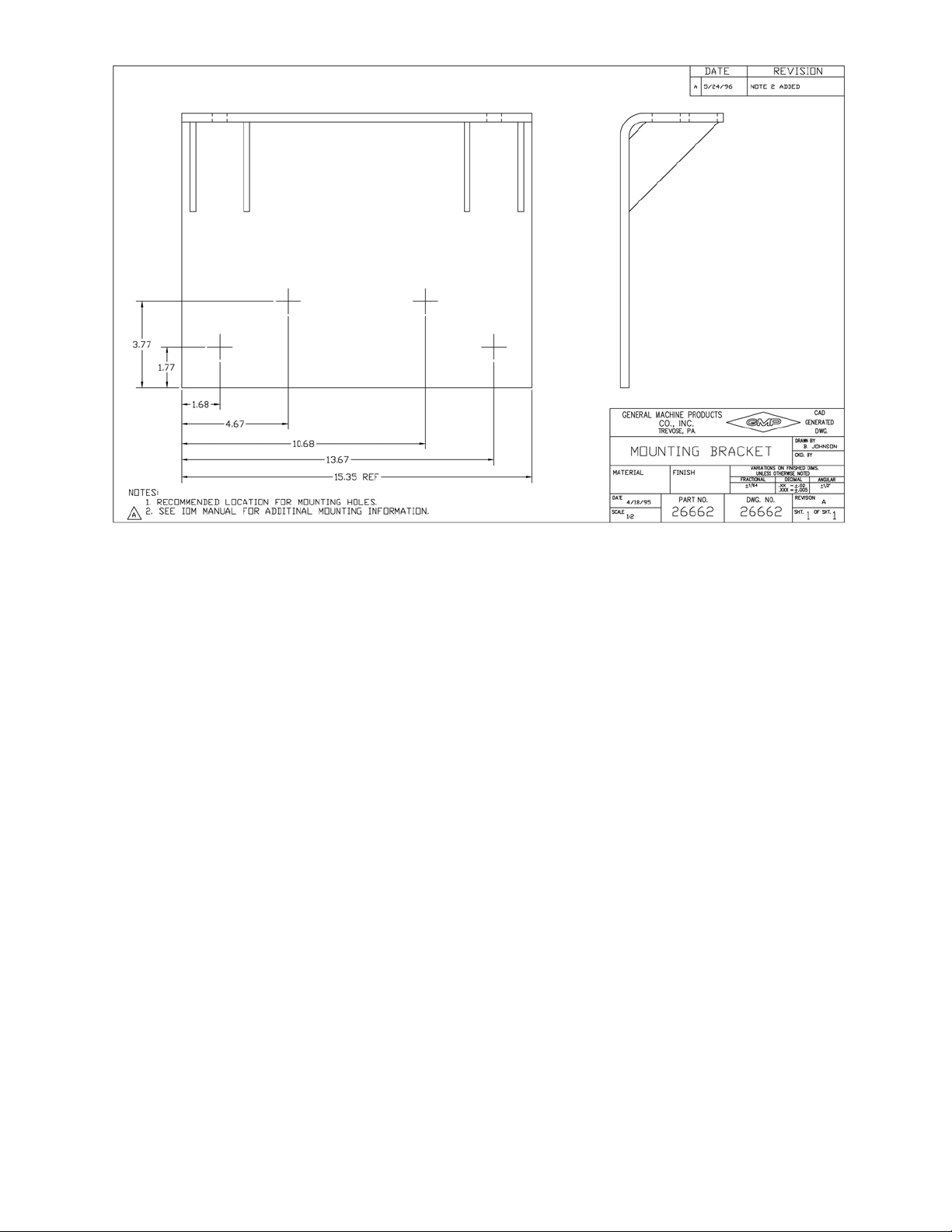
Refer to drawing 26662 for recommended mounting hole locations. The factory does not supply mounting fasteners to attach the winch mounting brackets to the vehicle chassis. Recommended fasteners are
four (4)
per winch installation. Using a drill diameter
1
/2 - 20 HHCS grade 8 bolts per each of the two mounting brackets for a total of eight fasteners
1
/32 in. greater than the nominal bolt diameter, drill a clearance hole through the mounting brackets and through the truck chassis. After the clearance diameter is
drilled, install the recommended fasteners into each hole and hand tighten with a lock washer and nut.
When using Huckbolt® fasteners drill the mounting brackets and truck chassis with the manufacturerʹs
recommended clearance drill.
When all of the bolts, lock washers, and nuts are in place, torque to the appropriate values for the fasteners used to mount the brackets to the chassis then torque to 160 - 180 ft.-lbs. (217 - 244 N·m) all eight
5
(8)
/8 - 11 HHCS grade 8 bolts.
It is recommended that the winch be directly mounted only to the truck chassis frame. It is not recommended to mount the winch to any other structural member, as on a sub-frame, without first contacting
the factory for specific application engineering support.
CAUTION! DO NOT WELD THE MOUNTING BRACKETS TO THE CHASSIS FRAME.
All of the mounting hardware (and the drum shaft extension if so equipped) is shipped in a parts box
attached to the winch or shipping crate.
IMPORTANT! To avoid corrosion problems when storing winches outside the parts boxes MUST be
removed and stored in an indoor area.
To protect the entire winch assembly against corrosion, various parts are sprayed with a corrosion inhibitor and the gearbox is filled with oil when shipped from the factory.
IMPORTANT! If the winch will be placed in outdoor inventory for an indefinite period, care should be
taken to prevent oil contamination or corrosion due to condensation.
IMPORTANT! BEFORE THE WINCH IS ACTUATED, THE ʺFULL LOAD BRAKEʺ MUST BE BLED.
See the instructions in Section 3.05 under the heading for ʺFULL LOAD BRAKEʺ.
CONTROLS - When the winch has been mounted, consideration must be given to the control of:
• Drum direction of rotation
• Drum speed
• Winch clutch control
• Drag brake caliper/actuator
A word on winch controls. The CD Lite may be ordered in one of three configurations: 1. Without controls for situations where the dealer is responsible for furnishing controls in conformance with Adams
CD Lite specifications and the customers requirements; 2. With an optional, manual control valve furnished by the factory and; 3. With an optional, remote fiber optic pendant control package furnished by
the factory.
Page 7
Page 9
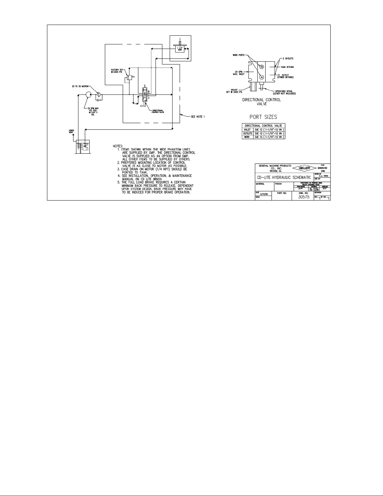
The control valve available from the factory as an option for the CD Lite winch has been selected specifically for this application. The internal piloted relief valve is pre-set at the factory, and needs no field adjustment. The porting on the control valve was selected to minimize the amount of reducing fittings
needed. The spool is spring loaded in both directions so when the operator releases the lever or handle
(not provided), the spool automatically centers and stops the flow of oil out of the work ports. There is
a ʺpower beyondʺ port on the valve for additional valves downstream.
The fiber optic pendant control allows the operator to be tethered to the vehicle via a fiber optic cord to
operate the winch by remote control. The system has been engineered and designed to provide a holistic approach to the design problem.
The system consists of a pressure generating valve, directional control valve with back cap, transmitter
with joystick, receiver and cabling. The joystick on the transmitter allows the operator to choose the direction and speed of the winch drum rotation. The fiber optic cable connects the transmitter and receiver. The fiber optic cable, being non-conductive, helps electrically isolate the operator from unintended electrical contact. The receiver accepts the signal from the transmitter and sends a digital signal
to the stepper motor in the back cap on the control valve. The control valve has all the features mentioned in the above section, plus the spool is positioned by the stepper motor. There are preprogrammed values (non- field adjustable) in the receiver for deadband position, ramps up and down
and flow adjustment. The values have been optimized for use with the CD Lite winch.
3.02 HYDRAULIC REQUIREMENTS
To obtain the maximum rated pull and line speed using the hydraulic motor supplied with the CD Lite,
the hydraulic system shall have a rated flow of 30 GPM (114 l/min.) maximum. Hydraulic system pressure shall be limited by a relief valve with a maximum setting of 2500 psi (17237
recommended hydraulic oil reservoir capacity is 60 gallons (227 l) of petroleum-based hydraulic fluid.
Recommended hydraulic line diameters are
3
/4 in. (19 mm) for: Pump to control valve; Control valve to
kPa). The minimum
Page 8
Page 10
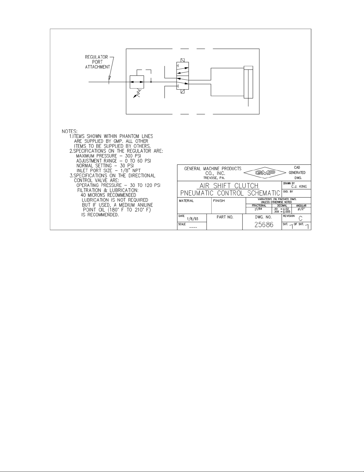
tank; Control valve through power beyond to hydraulic system; Control valve work ports to winch motor ports. Suggested Filtration, based on the hydraulic motor requirements, is 20 to 30 micron (nominal)
filters. Consult the filter supplier for specific filter recommendation.
The hydraulic motor case drain (
1
/4 NPT) should be ported to tank. Identification of connections from
the individual valve ports to the motor ports is shown in drawing 30575.
The full load brake requires a certain minimum amount of back pressure to release. Back pressure may
have to be induced dependent upon system pressure.
3.03 WINCH CLUTCH - The clutch plate is motivated by an air cylinder assembly that is
mounted to the hanger assembly. The fork is connected to the piston rod in the air cylinder and the fork
contains two cam followers which ride in a groove on the clutch plate. The air cylinder is plumbed to a
two position four-way directional control valve. The directional control valve is electrically operated,
and is rated for 12 volts DC with a continuous duty rating of 100%. A regulator is provided for maintaining a normal setting of 30 psi (207 kPa) supply pressure to the directional control valve. A Schradertype valve stem is provided on the regulator for connection of a pressure gauge to allow for monitoring
of the input pressure to the cylinder during regulator adjustment.
The regulator has a c in. PTF port for the incoming air supply. The directional control valve and the cylinder are plumbed at the factory. At the time of installation, the only connection required is the air supply line to the aforementioned regulator port. Refer to drawing 25686.
Page 9
Page 11
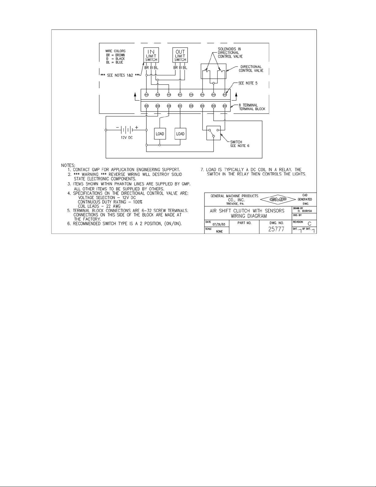
A terminal strip is provided for the electrical connection to the directional control valve. The terminal
strip is located on the hanger assembly on the outboard side. A two position switch should be used to
energize the solenoids in the directional control valve. The solenoids control the positioning of the valve
spool thereby directing the airflow to the two ports on the air cylinder. There are eight screws on the
terminal strip. Three screws are for the directional control valve and four screws are for the limit sensors. Refer to drawing 25777 for a schematic depiction of the electricial connections.
Important! Reverse wiring will destroy the solid state electronic components in the sensors.
The fork attached to the piston rod moves the clutch plate after the switch is activated. However, the
drum shaft may have to be rotated slowly to ensure full travel of the clutch plate and completion of the
engagement cycle.
A clutch position sensing feature is standard equipment on the CD Lite winch. The output can be wired
to a set of lights to provide the operator with an indication of clutch engagement or disengagement.
The air cylinder that actuates the clutch is equipped with a solid state digital output limit sensor at each
end of the cylinder. When the sensor detects the magnetic piston, the current sinking device completes
the circuit by connecting the load to the ground. The sensors are magnetically activated and while the
work on the same principle as Hall effect sensors, they are extremely more sensitive. The sensors are
100% solid state devices. They have no moving parts to wear, break, bounce or stick and they are fully
encapsulated in plastic resin.
Page 10
Page 12

The sensors should be wired as per drawing 25777. The sensors detect the magnetic piston in the air cylinder and not the switch used to activate the directional control valve, so even manual actuation of the
clutch is detected by the sensors.
3.04 CALIPER TYPE DRAG BRAKE - For reasons of safety and convenience, the drag brake is
equipped with a remote actuator. The remote actuator, reservoir and flexible hose section are shipped
loose with other winch mounting hardware in the parts box. These components are to be installed by the
dealer who will also furnish and install the hydraulic line running from the hydraulic actuator in to the
hydraulic port of the caliper brake assembly.
3.041 GENERAL GUIDELINES - Hydraulic brake components are precision built mechanisms and
must be treated as such. Certain procedures must be followed at the time of installation to be assured of
their optimum performance, and a few of the more common procedures are listed below:
To properly locate the brake component or brake line, you must always try to...
• Make it convenient for the operator.
• Use the shortest and most protected route.
• Avoid mounting near the engine, exhaust lines, muffler or anywhere that heat may be generated.
NOTE: Excessive heat transferred to the brake fluid may result in damage to the lines or seals.
• Mount the reservoir higher than the brake component to facilitate bleeding.
To properly mount components and brake line to withstand the most severe vibration and service conditions, always try to:
Use the right size bolt for the hole and secure with a steel lock washer.
Secure tubing to frame with proper size tube clamps to avoid possible fractures or fittings loosening and
leaking.
Use good, factory-flared lengths of steel tubing. Hand-made flares, when used, should be double flared.
Any flash or loose particles must be removed.
Use flexible brake line between frame and body.
If tubing passes through frame or fire wall a grommet or some other means should be used to protect
line from chafing.
Use tubing rated for 1500 psi (10342 kPa) minimum for the line between the actuator and the caliper
brake assembly.
The proper removal of air from the brake system is very important. All too often, air has remained
trapped in systems causing a ʺspongyʺ actuator and inadequate braking. The bleeder screw in the brake
assembly must be toward the top. The air in the system will always seek the highest level. To properly
bleed system...
• Be certain that fittings are tight to avoid leaking.
• Depress the actuator and open up the bleeder screws to allow the air to escape.
Page 11
Page 13

• Re-tighten the bleeder screws and allow the actuator to return.
• Repeat the cycle until actuator is firm.
• Make several static brake applications and then repeat the cycle once more.
The closed circuit hydraulic system must not leak. Even the smallest leak could defeat what would otherwise be a well operating and effective brake system. It could eventually deplete the reservoir and reduce the braking pressure. To avoid leaks...
• Check connections during the bleeding and static brake processes to be sure they are tight.
• Always re-install new hoses, lines and fittings if they look the least bit questionable.
It is impossible to over emphasize the importance of cleanliness at installation. Always...
• Use good, clean, quality fluid which conforms to S.A.E. Spec. No. J 703 or D.O.T. 3 or 4. Do not
use
hydraulic oil.
• Be sure all fittings and seats are clean before making connections.
• Clean the top of the reservoir before removing filler cap.
CAUTION: As a part of routine maintenance, it is recommended that brake hoses and brake lines be
inspected regularly. All damaged or worn parts should be replaced. The reservoir
should be checked for brake fluid level and clean brake fluid added as required.
3.042 INSTALLATION OF RESERVOIR AND ACTUATOR - The remote actuator is normally
mounted at the rear of the body, under the tail shelf. Find a location that is safe and convenient to the
operator and within sight of the winch operation. Alternate mounting would be in accordance with end
user specifications.
The reservoir should be mounted above, and as close as possible to, the inlet fitting of the actuator. Both
the inlet and outlet fittings of the actuator are
The caliper brake assembly is mounted at the factory on a bracket attached to the hanger. The reservoir
should be mounted higher than the caliper brake assembly to facilitate bleeding.
The flexible hose should be connected to the outlet fitting of the actuator.
1. Mount actuator assembly, using four
required. Note: bracket may be used as template for drilling mounting holes.
2. Install the hydraulic line running from the hydraulic actuator in to the inlet port (
the caliper brake assembly. The brake line should be rated for 1500 psi (10342 kPa) minimum.
Make the necessary hydraulic connections to the reservoir and actuator.
3. The closed circuit hydraulic system is shipped void of any fluid. Fill the system with brake
fluid, do not use hydraulic oil.
4. Bleed the system making sure all air is removed from the system. Apply hydraulic pressure
and check for leaks. Make several applications to be sure actuator is working properly.
5. After bleeding is complete, check reservoir for brake fluid level and add brake fluid if necessary.
Page 12
1
/2 - 20 UNS.
5
/16 in. diameter bolts, lock washers and locking nuts, as
1
/8 - 27 NPT) of
Page 14
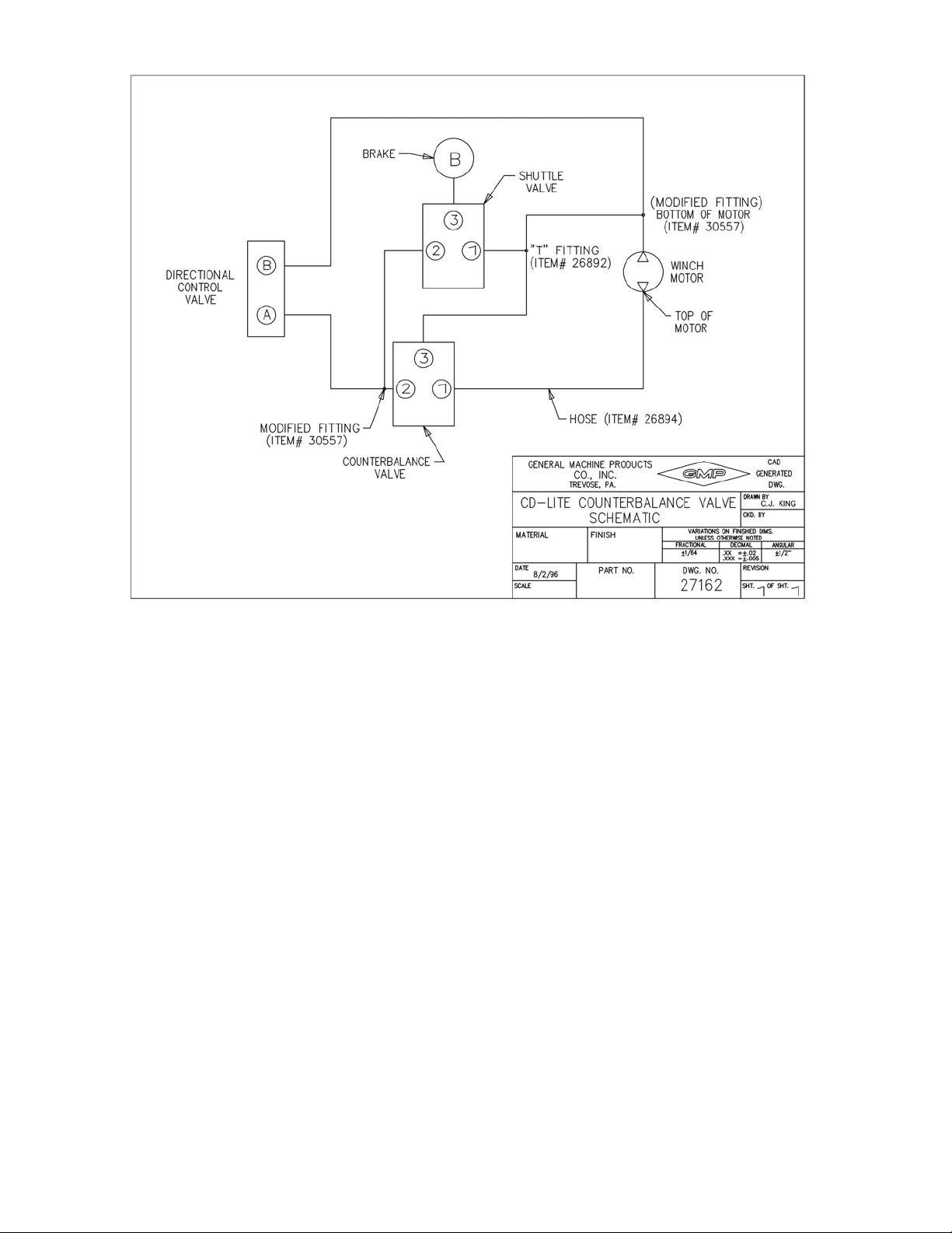
3.05 FULL LOAD BRAKE - Although the full load brake is factory installed, the mounting and
plumbing of the brake counterbalance valve and the brake bleeding procedures must be followed during installation of the winch to ensure proper brake operation.
3.051 INSTALLATION OF THE BRAKE COUNTERBALANCE VALVE
A counterbalance valve is a part of the brake system and helps to increase the responsiveness of the
brake and improve the load control capabilities of the winch. The counterbalance valve and hoses are
shipped loose in the parts box and require mounting and plumbing at the time of the winch installantion.
The 24 in. hose P/N 26894 must be connected from the motor port to the #1 port on the counterbalance
valve. The line from the directional control valve must be connected to the #2 port on the counterbalance valve. The smaller 15½ in. hose P/N 25369 must be connected from the ʺTʺ fitting on the motor
port to the #3 port on the counterbalance valve. Refer to drawing 27162 for more information.
The counterbalance valve has two through holes for mounting fasteners (not supplied). The supplied
hoses will allow mounting of the counterbalance valve in close proximity to the winch hydraulic motor.
Page 13
Page 15
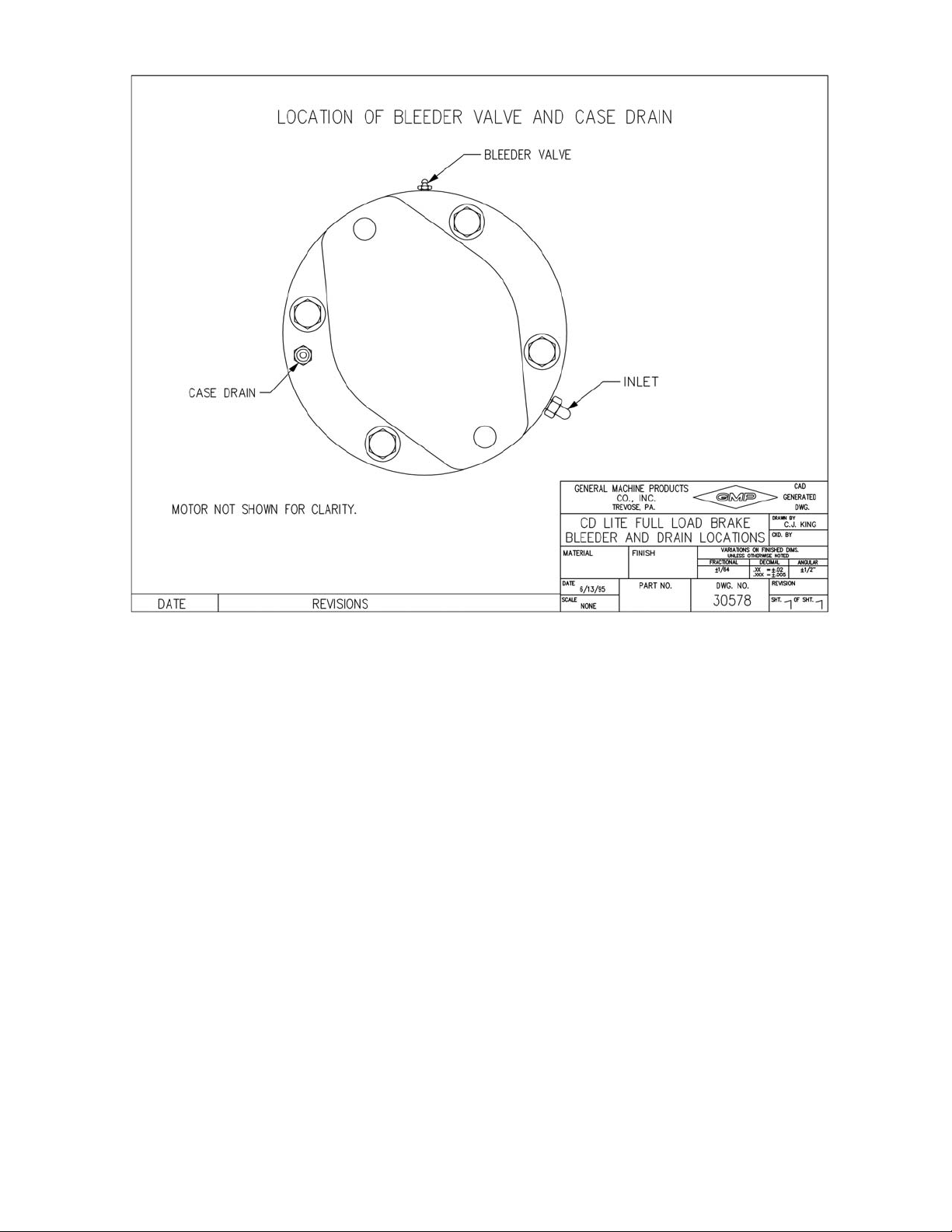
3.052 REQUIRED BLEEDING OF THE FULL LOAD BRAKE SYSTEM
Bleeding the full load brake is required anytime air has been introduced into the system, and must always be performed by the dealer during the winch installation, in order to assure proper release of the
brake for winch drum rotation. Bleeding is accomplished by pressurizing the system and loosening the
bleeder screw on the top of the brake (shown on drawing 30578). To avoid fluid loss or spillage, a hose
should be connected to the top of the bleeder screw and the outlet of the hose directed to a can or similar
container. The brake should be bled until all the air is removed from the brake. Several cycles of pressure bleeding may be required to remove all of the air from the brake.
The pressure from either side of the motor can release the brake. This feature enables the winch to pull
in as well as power out. The brake is not direction sensitive.
The maximum pressure rating is 3000 PSI (20684 kPa), including spikes or surges.
WARNING! SURGE PRESSURE IN EXCESS OF 3000 PSI (20684 kPa) GENERATED BY PUMP
SURGE OR RAPID OPENING OR CLOSING OF THE CONTROL VALVE WILL
CAUSE THE PISTON TO FRACTURE.
The O-rings (Buna ʺNʺ material) in the piston are only compatible with petroleum based fluid. DO NOT
USE NON - PETROLEUM BASED FLUID.
Page 14
Page 16

The brake is provided with a case drain. Should fluid leak into the brake housing, the case drain will
open to let the fluid escape. If fluid leaks from the case drain, contact the factory for assistance.
WARNING! THE FULL LOAD BRAKE MAY NOT HOLD THE RATED LOAD IF THE CASE
DRAIN IS LEAKING FLUID.
Any back-pressure in the tank return line may reduce the holding power of the brake. The brake is
spring applied and hydraulically released. The back-pressure may start to release the brake, thus reducing the holding power of the brake.
CAUTION! BENCH TESTING IS NOT RECOMMENDED BECAUSE IT MAY CAUSE DISTOR-
TION OF COMPONENTS OR BOLT FAILURE.
3.06 WIRE ROPE INSTALLATION - When installing the wire rope observe the following recom-
mendations: It is important to select the correct winch and wire rope for a particular application. Wire
rope is specified in terms of diameter, length, number of strands, number of wires per strand, composition of center core and direction of lay.
There is a definite advantage in applying wire rope of the proper direction of lay when spooling onto
the smooth surface of the winch drum. Wire rope with an improper lay will permit the coils to spread
apart each time the load is removed. Using wire rope with the proper lay will tend to keep the coils together when tension is removed. The correct lay will develop tight coils and even layers.
It is important to install the wire rope onto the winch drum with care. Kinking of the rope, caused by
the rope taking a spiral shape as a result of an unnatural twist, should be avoided.
When removing wire rope from the reel and spooling onto the winch drum, the reel must be supported
on a horizontal axis and free to rotate. Spool the rope onto the drum with the natural bend in the same
direction as it comes off the reel.
If wire rope is received in a coil, it should be unwound with the coil in the vertical plane. Again, spool
the rope onto the winch drum with the natural bend in the same direction as it was on the coil. Reverse
bending of the wire rope should always be avoided or kept to a minimum.
IMPORTANT! Wire rope should always be under tension when spooling onto the winch drum.
When the winch drum is in free spool and the drum shaft extension only is being used with a capstan or
reel, hook the pulling eye to a fixed section of the chassis. This will prevent the rope from unwinding or
ʺclock-springingʺ during the operation of the drum shaft.
Likewise, when the winch is not in operation, attach the winch line quick hook to a solid member on the
tail shelf and slowly take up the slack. This will best maintain the rope under a slight amount of tension
until required again and will prevent the rope from unwinding or ʺclock-springing.ʺ
3.07 WINCH DRUM ROTATION - The CD Lite is designed for typical ʺunderwindʺ applications.
UNDER-WINDING is when the winch drum rotates in a counterclockwise direction (viewing from the
Page 15
Page 17

right side) and the wire rope is spooled onto the winch drum at the bottom. As with any winch, it is imperative that the wire rope be attached to the correct side of the drum for the specific direction of the lay
of the rope given the direction of drum rotation. When the drum will be underwinding
is spooled in, use the rope clamp on the side of the drum which is opposite
For example, if using right lay rope on an underwind drum attach the wire rope to the left side rope clamp.
For the underwind application, the wire rope must have unrestricted travel from the tail shelf sheave to
the winch drum. Be certain that the wire rope will be able to freely traverse the entire width of the
drum. Application engineering assistance is available from the factory.
WARNING! The cable clamp alone is not designed to hold the rated load. Approximately ½ of the
first layer of winch line must be left on the drum to achieve the rated load and avoid
cable clamp failure.
of the lay of the wire rope.
as the wire rope
3.08 WINCH IDENTIFICATION - Manufacturer or dealer assistance is available to help resolve
unique problems. When contacting your local dealer or the factory, proper assistance can be offered if
the model and serial number of the winch in question is specified. This information is stamped on a
nameplate affixed to the gearbox or winch frame.
4. PRE-OPERATIONAL CHECKS
IMPORTANT CHECKS TO BE MADE BEFORE PLACING THE WINCH IN SERVICE:
Make certain that the winch assembly is properly secured to the chassis frame.
The operator shall have a complete understanding of all functions and the location and operation of all
controls.
The winch line should be spooled on the drum with tight, even, coils and lays.
It is not necessary to have the drum filled with winch line. Additional pulling capability can be obtained by only installing a slight excess of the maximum length required for the job, while also improving the laying of winch line on the drum.
Refer to the operating manual for the vehicle for specific operational instructions on the hydraulic system.
Check the hydraulic system to make certain that the reservoir is filled to the correct level with the
proper grade of oil.
Make certain that the reservoir shut-off valve is open.
Check the hydraulic system for the correct pressure and flow.
Check all winch and winch accessory gear housings for the correct oil level and grade.
See Section 6.02, LUBRICATION.
Page 16
Page 18

Engage the hydraulic pump drive and allow the oil to circulate and warm up for a few minutes before
operating the winch. This is particularly important during extremely cold weather.
Check operation of the drag brake.
Check the body load area in a triangular section between the tail shelf sheave and both drum flanges for
obstructions that could restrict the travel of the winch line or level wind.
IMPORTANT! BEFORE THE WINCH IS ACTUATED, THE FULL LOAD BRAKE MUST BE BLED.
See Section 3.05, INSTALLATION.
Make sure the full load brake and drag brake have been bled to assure positive activation of the brakes.
See Section 3 for procedures.
5. OPERATING INSTRUCTIONS
The following procedures must be observed to assure safe and efficient winch operation:
Refer to operating manual for the vehicle for specific operational instructions on the hydraulic system.
Check the body load area to make certain there are no tools or equipment to restrict winch line travel or
level wind movement.
Check the lay of the winch line on the drum and check for uneven build-up of the winch line.
Check to be certain that the winch clutch is fully engaged, as described in Section 2, PRECAUTIONS.
With rotation stopped, place the winch clutch control switch in the desired position for either paying
out or winding in.
Operate the directional control valve to achieve the desired direction of drum rotation.
Pull the load steadily and evenly.
To stop the winch, release the directional control valve lever.
When free spool is required, stop the drum rotation and disengage the clutch by moving the control
switch to the free-spool position.
To control the drum speed in free spool:
Use the caliper brake actuator lever and apply pressure according to the amount of braking required to
keep the drum from over-spooling.
CAUTION! THE DRAG BRAKE IS USED TO CONTROL THE DRUM SPEED ONLY. IT IS NEVER
TO BE USED TO HOLD THE LOAD.
Page 17
Page 19

When finished with the winch and it is desired to stow the free end of the winch line, hook the winch
line pulling eye to a fixed section of the chassis. A slight tension should be maintained in the winch line,
preventing the formation of loose wraps on the drum.
6. MAINTENANCE
6.01 GENERAL - Inspection of the winch and related components should be a continuing proce-
dure. The operator should be constantly alert to detect unusual noises, excessive oil leakage and overheating. The operator should report immediately any changes in the normal characteristics of the winch,
winch accessory or the hydraulic system.
If the winch has not been used for an extended period of time, a thorough inspection is warranted. Particular attention should be given to any damaged bearings, seals or gaskets. The oil should be checked
for contamination, abrasive foreign particles and lubrication qualities. As required, oil should be added
or completely drained and filled.
The wire rope should be inspected visually for kinks, bends, cuts or broken strands while operating.
Wire rope that does not meet OSHA criteria must be replaced.
Depending on the total length of the wire rope versus the length most often used, it is possible that the
top lays will show the most wear. To obtain additional life, subject to the proper conditions, the rope
can be rotated end for end.
The hydraulic system should be checked periodically for:
*Overheating
*Abnormal noise
*Maintaining a clean, sufficient, quantity of hydraulic oil of the proper grade.
*Keeping all connections sufficiently tight to prevent oil leakage and air from entering the system.
*Changing the hydraulic system oil filter at the frequency recommended by the filter manufacturer.
IMPORTANT! BEFORE THE WINCH IS ACTUATED, THE FULL LOAD BRAKE MUST BE BLED. See
Section 3.05 FULL LOAD BRAKE.
WARNING! THE FULL LOAD BRAKE MAY NOT HOLD THE RATED LOAD IF THE CASE
DRAIN IS LEAKING FLUID.
IMPORTANT! THE LOAD HOLDING ABILITY OF THE FULL LOAD BRAKE SHOULD BE TESTED
ON A PERIODIC BASIS.
6.02 LUBRICATION - An ongoing routine for assuring proper lubrication should be a part of the
overall maintenance program.
The gearbox oil reservoir must be checked and maintained. To check for the proper oil level, remove the
oil level plug in the side of the gearbox. The lubricant should be maintained to the height of the oil level
opening. To add oil, remove the filler plug on top of the gearbox. Add 80W 140 oil as required to bring
Page 18
Page 20
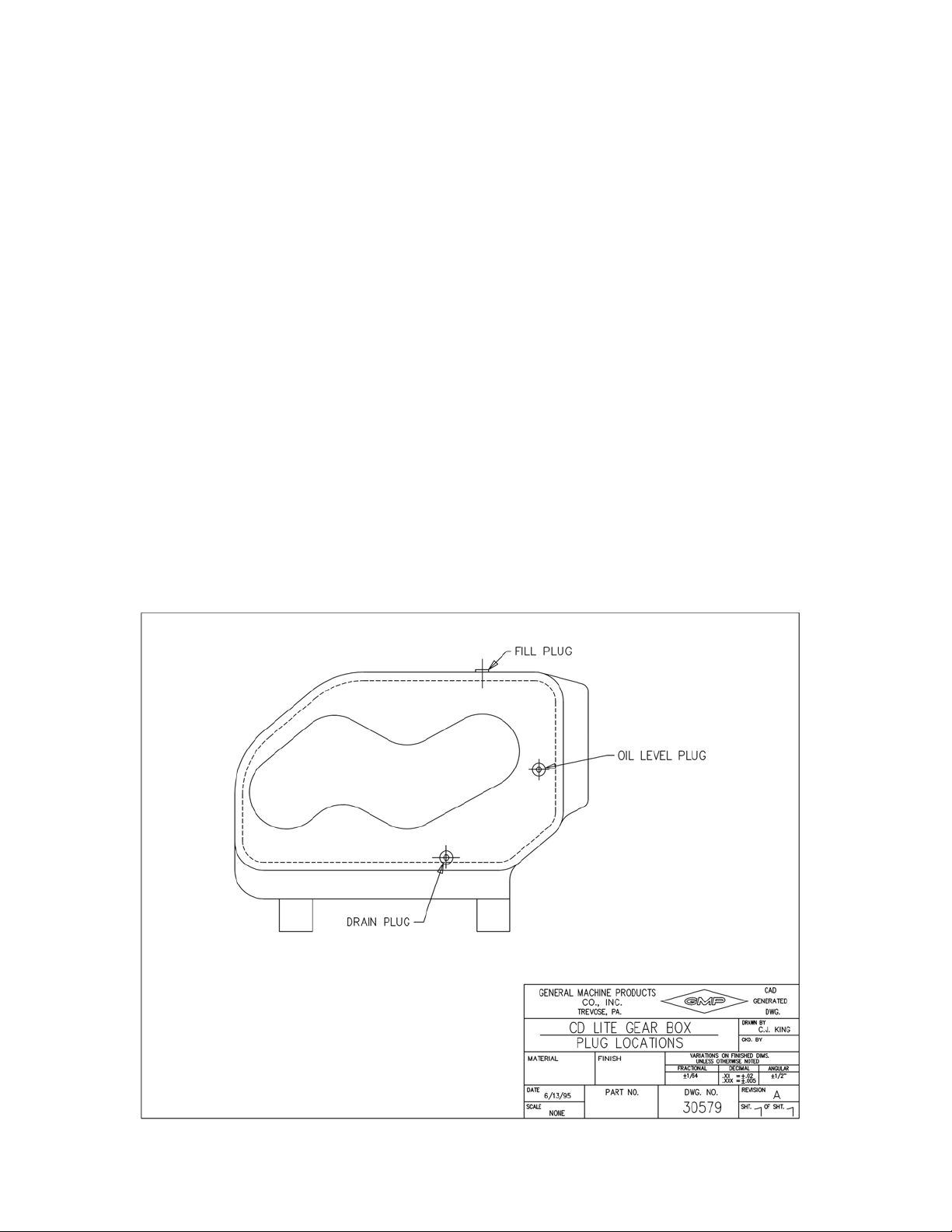
the oil level up to the level of the oil level plug opening in the side of the gearbox.. The oil will just start
to run out of this opening when the proper level has been reached. Do not overfill the gearbox! The oil
level plug in the side of the gearbox must always be removed before adding oil to avoid over-filling.
When the correct oil level is reached, screw the oil level plug back into the side of the gearbox and screw
the oil fill plug into the top of the gearbox.
The gearbox oil level should be checked every seventy-five (75) hours of operation and should be completely drained and filled with new oil at least every other year. The drain plug is located on the side of
the gearbox (see drawing 30579). To drain the gearbox, remove the oil drain plug. Remove the filler
plug in the gearbox cover. After the gearbox is completely drained, reinstall the oil drain plug. Add
3.75 quarts (3.5 l) of fresh 80W 140 oil as described above and reinstall filler plug.
Apply a coat of engine oil to all chain drives every seventy-five (75) hours of operation. The lubricant
should be applied on the inside surface of the roller chain by means of a spray or brush.
When the winch is not in operation, hook the pulling eye to a fixed section of the chassis. Slowly take
up the slack. This will best maintain the rope under a slight amount of tension until required again.
Wire rope is considered to be a machine, having many moving parts. Each time the rope bends or
flexes, the various wires and strands slide over each other. Lubricating the wire rope periodically will
minimize friction and extend life expectancy. The type of lubricant, method and frequency of application is dependent on each particular circumstance. For specific lubrication details, contact the wire rope
manufacturer.
Page 19
Page 21

6.03 WINCH IDENTIFICATION - Manufacturer or dealer assistance is available when needed to
assist in resolving unique maintenance problems. When contacting your local dealer or the factory,
proper assistance can be offered if the model and serial number of the winch in question is specified.
This information is stamped on a nameplate affixed to the gearbox.
6.04 CALIPER BRAKE - It is recommended that brake hoses and brake lines be inspected regu-
larly. All damaged or worn parts should be replaced. The reservoir should be checked for brake fluid
level and clean brake fluid added as required.
See Section 3.04 CALIPER BRAKE for Special Instructions on Bleeding.
7. REPLACEMENT PARTS
Replacement parts information can be found on the ensuing pages. If parts other than those illustrated
are required, please contact the factory for specific application engineering support.
© General Machine Products Co., Inc. 3111 Old Lincoln Highway, Trevose PA 19053-4996 USA
Tel: 1 215 357 5500 Fax: 1 215 357 6216 e-mail: [email protected] http://www.GMPtools.com
Page 20
Page 22
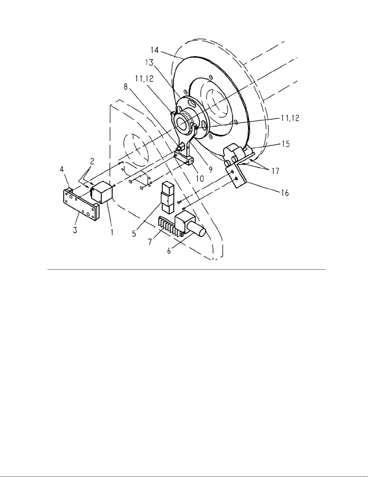
AIR SHIFT CLUTCH AND CALIPER BRAKE—PARTS LIST
Figure 1A
ITEM ITEM # DESCRIPTION REQD.
1 26857 AIR CYLINDER 1
2 26858 AIR CYLINDER SENSOR (NOT SHOWN) 2
3 30485 MOUNTING PLATE - AIR CYLINDER 1
4 26849 SPACER BLOCK 2
5 25678 AIR VALVE 1
6 25675 REGULATOR 1
7 25868 TERMINAL CONNECTOR 1
8 30487 ROD EYE 1
9 30484 SHIFTER FORK 1
10 30486 SHIFTER MOUNT 1
11 30553 BEARING 2
12 17811 NUT 10-32 ESN 2
13 30479 CLUTCH PLATE 1
14 26474 CALIPER BRAKE DISC 1
15 26588 CALIPER BRAKE 1
16 26560 BRAKE MOUNT - CALIPER BRAKE 1
17 26590 SHOULDER SCREW 5/16" DIA. X 1/4" LG. (NOT SHOWN) 2
18 17135 ACTUATOR (NOT SHOWN) 1
19 17136 RESERVOIR (NOT SHOWN) 1
20 17137 HOSE (NOT SHOWN) 1
Page 23
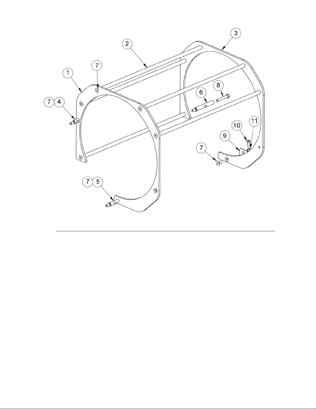
DRUM GUARD—PARTS LIST
ITEM P/N DESCRIPTION REQ'D.
1 26716 DRUM GUARD PLATE GEAR BOX SIDE 1
2 26721 DRUM GUARD ROD 5
3 26715 DRUM GUARD PLATE HANGER SIDE 1
4 26719 SHORT SUPPORT SHAFT 1
5 26718 MEDIUM SUPPORT SHAFT 1
6 26717 HANGER SUPPORT SHAFT 1
7 26871 SCREW 5/16 X 3/4” FLAT HD. 12
8 25516 HEX BOLT 5/16-18 X 2” 1
9 26720 MOUNTING PLATE 1
10 26872 SCREW 5/16-18 X 5/8” BUTTON HD. 1
11 09940 NUT 5/16-18 ELASTIC STOP 1
Page 24
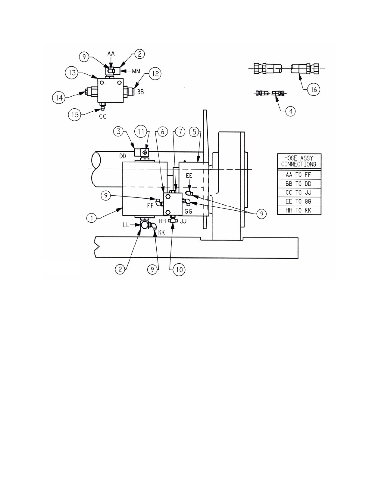
MOTOR / FULL LOAD BRAKE / SHUTTLE VALVE PARTS LIST
Figure 3A
Item P/N Description Req'd.
1 27024 MOTOR, SINGLE-SECTION HYDRAULIC 1
2 30557 FITTING, RIGHT HAND 2
3 30559 FITTING, LEFT HAND 2
4 25369 HOSE ASSEMBLY –4 4
5 26345 BRAKE, FULL LOAD 1
6 25362 BLOCK, SHUTTLE VALVE 1
7 25363 CARTRIDGE, SHUTTLE VALVE 1
8 26587 BRACKET, SHUTTLE VALVE (NOT SHOWN) 1
9 25365 FITTING, 90º SAE 6
10 26892 FITTING, TEE SAE 1
11 26893 FITTING, PLUG SAE 1
12 26890 FITTING, STR. THD. #12 SAE 1
13 27029 BODY, COUNTERBALANCE VALVE 1
14 27030 CARTRIDGE, COUNTERBALANCE VALVE 1
15 26891 FITTING, #4 TO #6 SAE 1
16 26894 HOSE ASSEMBLY –12 1
Page 25

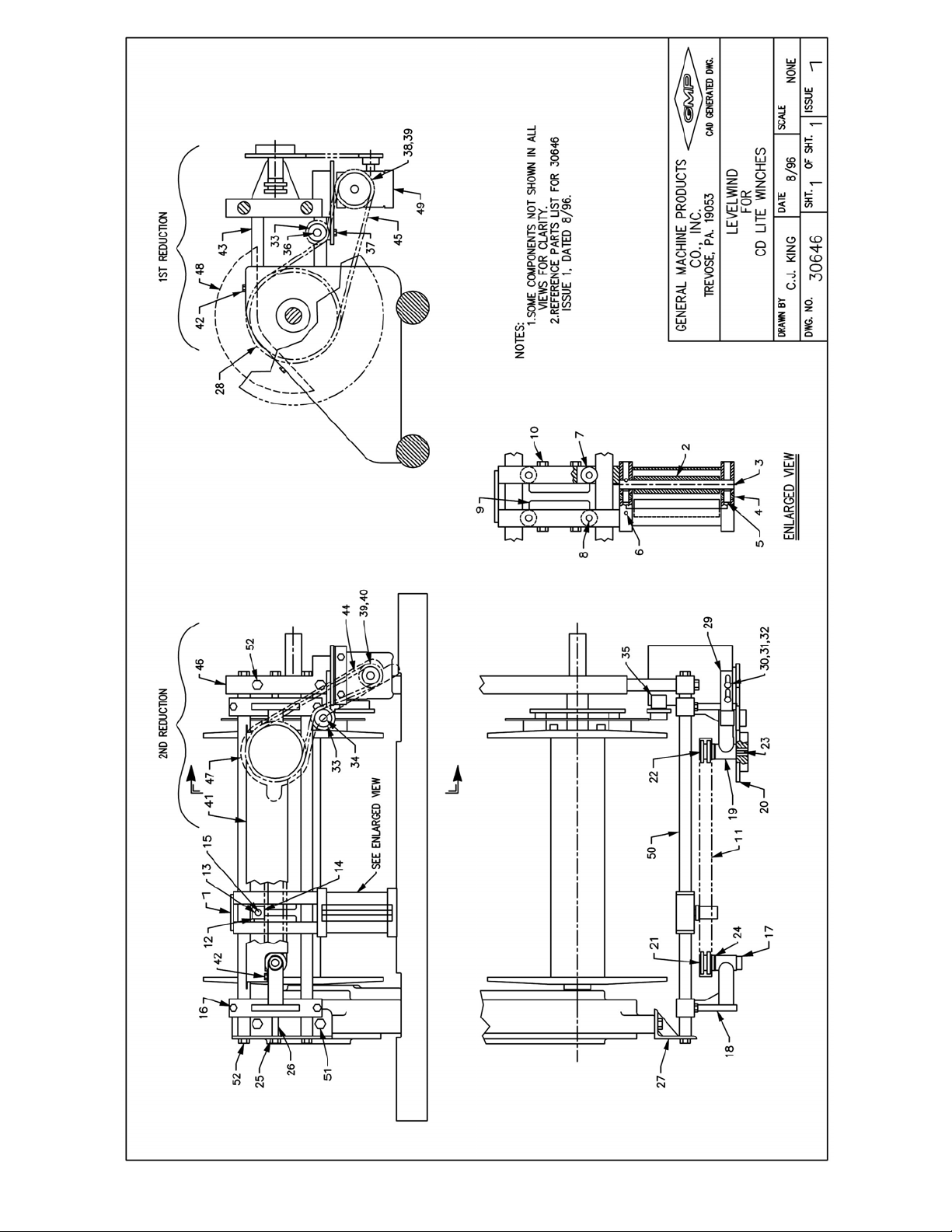
PARTS LIST FOR ADAMS CD LITE LEVELWIND
Item Part # Dwg. # Description Reqd.
1 27032 Carriage Assy. (Includes Items 2,3,4,5,6,7,8) 1
2 26517 26517 Roller Assy 2
3 26516 26516 Shaft 2
4 26519 26519 Guide Roller 2
5 26518 26518 Guide Roller Shaft 2
6 02864 Commʹl Rollpin 3/16ʺ x 1-1/2ʺ 2
7 27033 Roller Assembly 4
8 26870 Commʹl Shoulder Screw 1/4ʺ Dia. x 1ʺ Lg. 4
9 26845 26845 Guide Plate 2
10 26575 Commʹl Cap Screw Hex Hd. 1/4ʺ-20 x 1-1/4ʺ 4
11 26578 Cross Chain Assy. 1/2ʺ Pitch, 80 Pitches 1
Double Width Roller Chain
12 26545 26545 Drive Pin Block 1
13 26596 Commʹl Woodruff Key 1/8ʺ x 1/2ʺ 1
14 26881 Commʹl Cap Screw But Hd. 6-32 x 1/4ʺ 4
15 26544 26544 Drive Pin 1
16 26589 Commʹl Cap Screw Hex Hd. 3/8ʺ-16 x 1-1/4ʺ 4
17 26585 Commʹl Collar w/set Screw 1
18 27035 Bracket Assembly 1
19 27035 Bracket Assembly 1
20 26584 Sprocket 30 Tooth 1
21 26512 26512 Sprocket 10 Teeth, 1/2ʺ Pitch, 1
Double Width Roller Chain, Short.
22 26513 26513 Sprocket 10 Teeth, 1/2ʺ Pitch, 1
Double Width Roller Chain, Long.
23 26591 Commʹl Woodruff Key 3/16ʺ x 3/4ʺ 1
24 26514 26514 Thrust Washer 2
25 16068 Commʹl Nut 1/2ʺ x 13 2
26 26592 Commʹl Set Screw 1/2ʺ-13 x 3ʺ Lg. 2
27 26558 26558 Support Bracket 1
28 26475 26475 Sprocket F/Winch Drum (Replacement) 1
48 Tooth, 1/2ʺ Pitch Roller Chain.
29 27036 Idler Bracket Assembly Second Reduction 1
30 26595 Commʹl Cap Screw Soc. Hd. 5/16ʺ-18 x 1-1/4ʺ 2
31 09023 Commʹl Washer 5/16ʺ 2
32 30580 Commʹl Nut 5/16ʺ - 18 ESN 2
33 26593 Sprocket Idler 11 Teeth 2
34 27037 Idler Shaft Assembly Second Reduction 1
35 27038 Idler Bracket Assembly First Reduction 1
36 27039 Idler Shaft Assembly First Reduction 1
37 26875 Commʹl Cap Screw Hex Hd. 5/16ʺ-18 x 3/4ʺ 1
38 26582 Sprocket 15 Teeth, First Reduction 1
39 17839 Key 3/16ʺ Square x 1ʺ Lg. 2
Page 24
Page 26

PARTS LIST FOR ADAMS CD LITE LEVELWIND
(CONTINUED)
Item Part # Dwg. # Description Reqd
40 26583 Sprocket 9 Teeth, Second Reduction 1
41 26839 26839 Cross Chain Guard 1
42 26874 Commʹl Cap Screw Hex Hd. 1/4ʺ-20 x 1/2ʺ 4
43 26493 26493 Support Rod 2
44 26576 Second Reduction 1/2ʺ Roller Chain, 1
62 Pitches, Includes Connecting Link
45 26581 First Reduction 1/2ʺ Roller Chain, 1
81 Pitches, Includes Connecting Link
46 26505 26505 Pedestal 1
47 27040 27040 Chain Guard Second Reduction w/Bracket 1
48 26722 26722 Chain Guard First Reduction 1
49 27041 Reducer Assembly 1
50 26496 26496 Guide Rod 2
51 26878 Commʹl Cap Screw Hex Hd. 1/2ʺ-13 x 1-1/4ʺ 2
52 26877 Commʹl Cap Screw Hex Hd. 1/2ʺ-20 x 1-1/2ʺ 6
Page 25
Page 27
Page 28

1a. General Machine Products Co., Inc. ("GMP") warrants to the purchaser and/or end
user:
(1) that a new product sold and manufactured by GMP will be free from original defects in
material and workmanship for one year from the date the product was delivered to the
purchaser and/or end user, or for the lifetime of the Modular Plug Presser;
(2) that a new product sold and not manufactured by GMP will be covered exclusively by
the manufacturer's warranty. However, if that warranty coverage shall provide less coverage than the GMP Warranty for its manufactured products, then the warranty set forth in
Paragraph 1(a)(1) above shall apply instead;
(3) that a reconditioned used GMP product sold by GMP, or a non-owned product repaired
by GMP, or a new part sold by GMP, will be free from original defects in material and workmanship for ninety days from the date the product was delivered to the purchaser and/or
end user.
1b. The above warranties are contingent upon and subject to the condition that: (1) the
end user substantiates the date it purchased and received delivery of the product or part,
and (2) the product or part shall have been installed, maintained and used in accordance
with GMP's or the manufacturer's written instructions.
2. The end user shall determine the suitability of GMP's product or part for intended use,
and the end user assumes all risk and liability whatsoever in connection therewith except
to the extent set forth in this Limited Warranty.
3a. GMP reserves the right to request that the product or part be returned to us for examination and cannot be responsible for user charges incurred in the replacement of any product. GMP's agreement to repair or replace is also subject to its inspection of the product
and verification of the defect.
3b. Subject to immediate written notification of a defect or malfunction, GMP will repair or
replace that product or part, at GMP's option, returned freight prepaid to Trevose, PA.
3c. To obtain repair or replacement service under the Limited Warranty, the purchaser
must contact the factory for a Return Material Authorization (RMA). Once obtained, send
the RMA along with the defective part or product, transportation prepaid to:
General Machine Products Co., Inc.
3111 Old Lincoln Highway
Trevose, PA 19053-4996 USA
Tel: 215.357.5500
3d. The field labor and material charges incurred by an authorized GMP dealer or an end
user to disassemble, inspect, repair and reassemble our product or part at their respective
prime locations will not be reimbursed unless GMP has first reviewed and approved those
charges.
3e. Incidental repair charges incurred by an authorized dealer or an end user for items
such as labor, transportation, tolls, lodging and meals at a location remote from its prime
facility, or to demount our product or part from its remote location and forward to its prime
facility, are not the responsibility of GMP, and are not covered by this Warranty.
Page 29

3f. Incidental repair charges incurred by an authorized GMP dealer or end user to remove
construction hardware, modify a vehicle or otherwise gain access to GMP's product or part,
is a condition beyond GMP's control, and is not covered by this Warranty.
4a. GMP products or parts which become part of a total assembly which has been designated and/or manufactured by others, are not covered by this Warranty unless GMP reviews the total assembly and expressly extends its warranty.
4b. Design, material and workmanship furnished by others to install or operate a GMP product or
part are not covered by this Warranty with respect to GMP's products or parts which are used in that
particular assembly.
4c. Hydraulic, pneumatic, electrical or mechanical control equipment which is not manufactured by
GMP and which becomes a part of a GMP assembly, is not covered by this Warranty.
4d. This warranty does not cover a GMP product or part which others have subjected to
abuse, improper installation, improper operation, alteration or negligence in storage or
handling.
5a. THE ABOVE WARRANTIES ARE EXCLUSIVE AND ARE IN LIEU OF ALL WARRANTIES OF
MERCHANTABILITY, FITNESS FOR PURPOSE OR OTHER WARRANTIES OR GUARANTEES OF
ANY KIND OR DESCRIPTION, EXPRESS OR IMPLIED.
5c. GMP'S SOLE LIABILITY AND THE PURCHASER'S SOLE REMEDY FOR A FAILURE OF A
PRODUCT OR PART UNDER THIS LIMITED WARRANTY, AND FOR ANY AND ALL CLAIMS
ARISING OUT OF THE PURCHASE AND USE OF THE PRODUCT OR PART SHALL BE LIMITED
TO THE REPAIR OR REPLACEMENT OF THE PRODUCT OR PART THAT DOES NOT CONFORM
TO THIS WARRANTY.
6. GMP reserves the right, without notice, to make changes in equipment design or components as
progress in engineering or manufacturing methods may warrant.
7. This Warranty shall be construed in accordance with the laws of the State of Pennsylvania, of The
United States of America.
8. This Limited Warranty may not be modified, in whole or in part, except by writing signed by an authorized officer of GMP.
 Loading...