

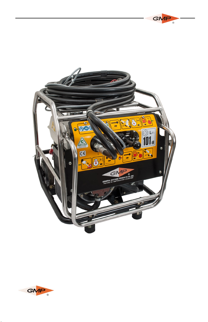
POWER PACK W/OIL COOLER
P/N 32800
OPERATION AND MAINTENANCE MANUAL
Copyright 2013 by General Machine Products Co., Inc
All rights reserved. No part of this publication may be copied,
reproduced or transmitted in any form whatsoever without the
written permission of General Machine Products Co., Inc.
GMP • 3111 Old Lincoln Hwy • Trevose, PA 19053 • USA
TEL: +1-215-357-5500 • www.gmptools.com
Page 1
General Machine Products Co., Inc.
Sept. 2013 USA ver 1
Manual P/N 33564
Introduction
To operate the power pack efficiently and safely you must know the power pack and
have the skill to use it. If you are a new operator, you should become trained in the
skills of using a power pack before trying to work with it.
It is assumed that personnel carrying out maintenance have at least a sound knowledge
of workshop practice, safety procedures and general techniques associated with the repair of hydraulic equipment.
It is expected that components will be thoroughly cleaned and lubricated, where appropriate, also that any opened hose connections will be blanked to prevent entry of dirt
and excessive loss of hydraulic fluid.
Serial numbers are stamped on a plate attached to the top of the unit.
It is important to quote the serial number when making repairs or ordering parts.
Safety Decals
Keep all decals clean and readable. Replace lost or damaged decals.
WARNING
!
Always use the fold down handles provided, when maneuvering the power pack.
Power packs are heavy pieces of equipment. Always adopt safe lifting practices
otherwise injury may occur.
Before Operating the Machine
Check for Cleanliness
Check for Damage
Check for Leaks
Make sure the fuel filler cap is tightly closed
Check Hydraulic Oil Level
Ensure the machine is positioned safely
Ensure that all hydraulic couplings are fully serviceable.
Ensure that any hydraulic tools you are planning to use are compatible with the mod-
el of the machine you are using.
Check Engine Oil Level
Check the Fuel
Never refuel with the engine running.
!
Page 2
General Machine Products Co., Inc.
Operating in Low Temperatures
Use the Correct Viscosity Engine Oil
See Engine Manufacturer's Handbook
Fill the Fuel Tank at the End of each Working Period
Protect the Machine When not in Use
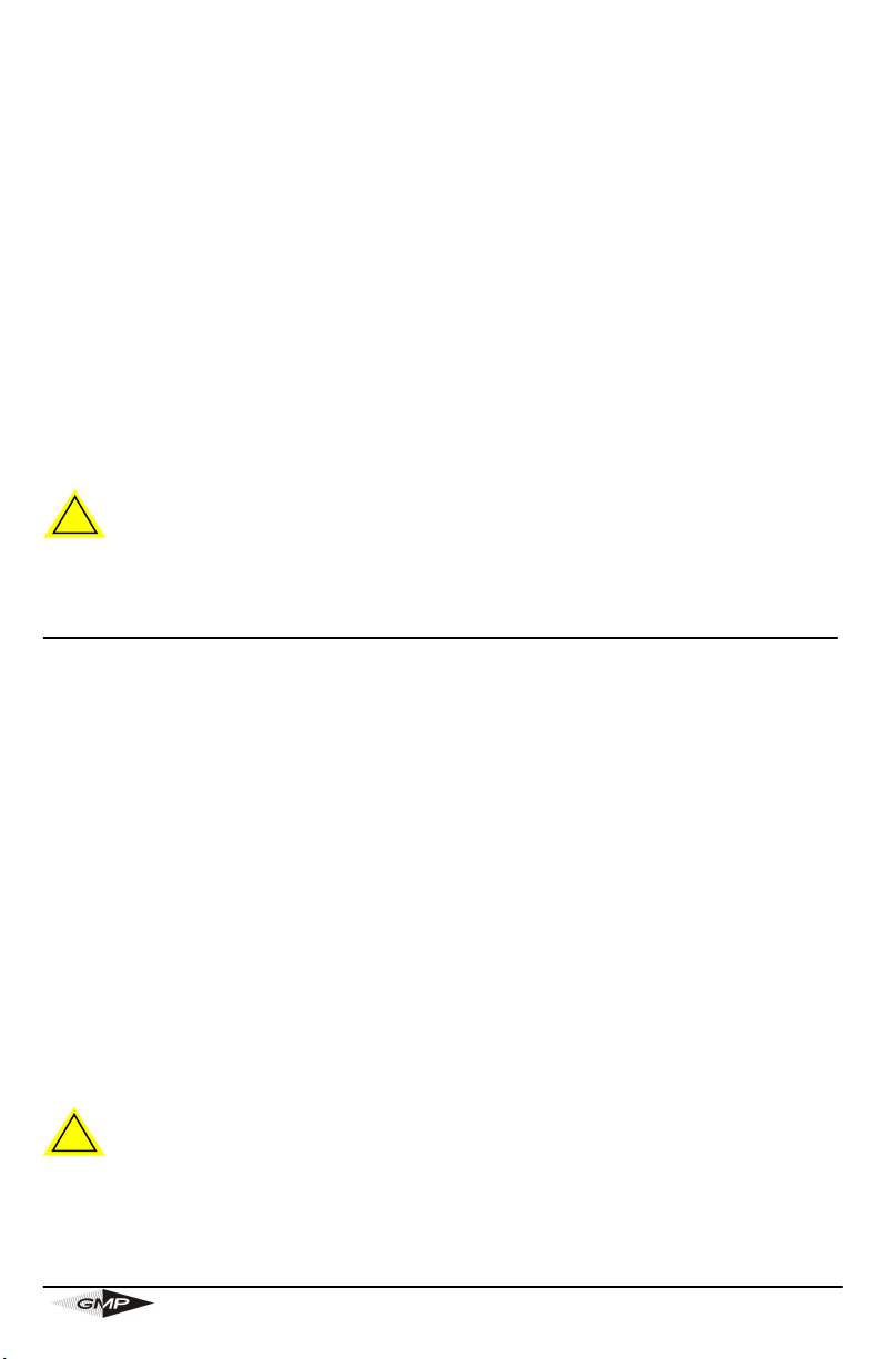
Hydraulic Output Control and Connectors (Fig. 1)
Hydraulic output control (1) is used to control the flow
rate to the tool in use.
The hydraulic power pack must be connected by the
two detachable hoses (2 & 3) to the driven machine by
plugging in the male/female quick release couplings
before starting the engine.
Important: Connect the electrical box on the Tornado.
Move the hydraulic control all the way to the right. Do
not try to start the engine on the Power Pack until the
hoses between the Power Pack and the remote equipment have been connected. Do not disconnect the hydraulic hoses when the power pack is running (if the
engine continues to run serious overheating will occur
as the oil continues to pass through the relief valve).
Fig. 1
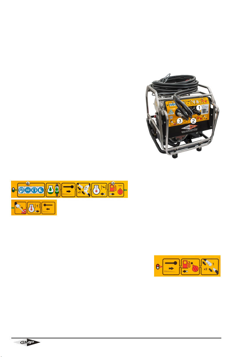
Starting/Stopping (Figs. 2/3)
Refer to the engine manual for additional information on starting the engine. Position the throttle lever at the
maximum setting after the choke is
open. Move the hydraulic output con-
Fig. 2
trol all the way to the left.
Honda GX240:
The engine is fitted with an Oil Alert system which is designed to prevent engine damage caused by an insufficient amount of oil in the crankcase. The oil alert system will
automatically shut down the engine before the oil in the crankcase can fall below a safe
limit.
Temperature Idling Time
below -20°C 5 minutes
-20°C to -10°C 2 minutes
-10°C to 5°C 1 minute
above 5°C 20 seconds
Recoil Start Models: Do not allow the starter grip to snap back against the engine. Return it gently to prevent damage.
Stopping the engine: Move the hydraulic output control all the way to the right. Refer
to the engine manual for additional information on stopping the engine.
Fig. 3
Page 3
General Machine Products Co., Inc.

Service Schedules
Apart from the daily jobs, the schedules are based on machine running hours. Keep a
regular check of hours in use. Do not use a machine which is due for a regular service.
Rectify any defects found during regular maintenance before clearing the machine for
use.
WARNING
!
Maintenance must be done only by suitably qualified and competent persons. Before
doing any maintenance, make sure the machine is safe and correctly situated on level
ground.
Daily
Clean machine generally. Clean the machine using water and/or steam. Do not al-
low mud to build up on tire engine. Make sure that the air inlets on the hydraulic
cooler are not clogged.
Check
Generally for damage
Hydraulic fluid level
Engine oil level
Hydraulic couplings
Hydraulic hoses
Note: Check tightness of nuts, bolts, screws and hose fittings after the first days operation and thereafter in accordance with Service Schedules.
Note: The engine oil should be replaced after the first three days operation and thereaf-
ter in accordance with the Maintenance Schedules
Every 50 hours or 3 Months
Do the Daily jobs plus:
Clean
Air cleaner elements.
(See Engine Manufacturer's Handbook)
Engine oil filter
Change
Engine oil
Hydraulic filter
Hydraulic oil
Page 4
General Machine Products Co., Inc.

Every 100 hours or 6 Months
Do the Daily and 3-monthly jobs plus:
Check:
Tightness of nuts, bolts, screws and hose fittings
Flow and pressure output
Change
Main hydraulic filter
Hydraulic fluid
Engine oil. (See Engine Manufacturer's
Handbook)
Clean
Fuel strainer
Spark plug
Check
Spark plug gap
Note: For detailed maintenance procedure, refer to Engine Manufacturer’s Handbook.
Checking the Hydraulic Fluid Level (Fig. 4)
1. Prepare the Machine
Position the machine on level
ground. Switch off the engine and
allow it to cool down.
2. Check the Hydraulic Fluid Level
a. Check the hydraulic fluid level
using sight gauge A.
b. If necessary top up the hydraulic
fluid through filler B.
Note: Use only the recommended hydraulic fluid.
Fig. 4
Changing the Hydraulic Fluid (Fig. 4)
Note: The illustration shown is for a typical machine.
1. Position the machine on level ground. Switch off the engine and allow it to cool
down.
2. Drain the Hydraulic Fluid
a. Place a container of a suitable size below the tank drain plug C to catch the fluid.
b. Remove drain plug C and filler cap B and allow fluid to drain out.
Page 5
General Machine Products Co., Inc.

3. Replace the Hydraulic Fluid.
a. Clean and refit drain plug C.
b. Pour fluid through filler until it reaches the required level on sight gauge A.
c. Refit filler cap B.
Note: Use only the recommended hydraulic fluid.
Changing the Main Hydraulic Filter (Figs. 5/6)
WARNING
!
Hot oil and engine components can burn you. Make sure the
engine is cool before doing this job. There may be limited fluid
spillage when the filter is removed. Clean any spillage immediately and dispose of materials in accordance with current regulations.
1. Position the machine on level ground. Switch off the engine
and allow it to cool down.
2. Place a container of suitable size beneath the filter to catch
any spilt fluid.
3. Remove the three bolts A securing the lid to hydraulic filter
housing B, and remove the lid.
4. Lift out and dispose of the used filter.
5. Push the new element C firmly into place in the
filter housing B.
6. Refit the lid on the filter housing B, ensuring that
spring clip D locates between spigots E. Secure
with the three bolts A.
7. Check the hydraulic fluid level, see Checking the
Hydraulic Fluid Level.
Fig. 5
Fig. 6
Cleaning the Cooler
The oil cooler fins may be cleaned using low pressure compressed air. Do not attempt to
clean using a wire brush as this could damage the fins.
Gaining Access to Machine Components (Fig. 7)
To facilitate easier maintenance, the tubular frame is fitted with hinge bolts. The frame
may be moved to afford ready access to the machine components in the following manner:
1. Remove and retain securing
clips (A).
2. Lift the tubular frame out of the
way of the machine components
by rotating it on bolts (B).
Page 6
General Machine Products Co., Inc.
Fig. 7

Note: It is important that after maintenance, the tubular frame is restored to its operating position and that the clips A are securely fitted.
Note: When the machine is to be lifted using the balanced lifting point C, it is important
to ensure that the clips A are in place and securely fitted.
TROUBLESHOOTING GUIDE
Engine Will Not Start
Check gas level
Check throttle in "on" position
Check emergency stop button is "reset" on either the Tornado or the Powered Duct
Rod Pusher
Ensure hoses are connected from power pack to blower (if they are not connected or
have a faulty coupling, engine will not turn over).
Contaminated gas
Difficult to Start Engine
Check above points
Ensure gas has additional additive
Engine may be flooded
Check hydraulic valve on blower unit is switched “off”
Check spark plug
Engine is Running Erratic
Ensure additive is mixed with gas
Damage to throttle
SPARES
For spare parts always provide the part number and serial number.
General Machine Products Co.
3111 Old Lincoln Highway, Trevose PA 19053 USA
TEL: +1 215 357 5500 ● FAX: +1 215 357 6216 ● E-MAIL: info@GMPtools.com
Website: www.GMPtools.com
Please give as much information as possible to ensure correct identification and
supply of spare parts
Page 7
General Machine Products Co., Inc.

SPECIFICATIONS
Flow: 0-5 GPM (0-20 LPM)
Pressure: 2000 psi (8 bar)
Honda Engine Type: GX 240 8 HP
Hydraulic Oil Type: Shell Tellus T-32 1.5 gal (7.0 L)
For Engine Details refer to engine manufacturers’ manual.
Page 8
General Machine Products Co., Inc.
 Loading...