

CABLE OVERBLOWING JUNCTION BOX
FOR 1 1/4” SDR DUCT
OPERATION & MAINTENANCE MANUAL
P/N 89066
Copyright 2012 by General Machine Products Co., Inc
All rights reserved. No part of this publication may be copied,
reproduced or transmitted in any form whatsoever without the
written permission of
GMP • 3111 Old Lincoln Hwy • Trevose, PA 19053 • USA
General Machine Products Co., Inc.
TEL: +1-215-357-5500 • www.gmptools.com
MAY 2012 USA Ver 1
Page 1 of 16
General Machine Products Co., Inc.
Manual P/N 33297

REVISION HISTORY
Rev # Date Details Author
01 05/31/12 Original Issue A Konschak
CONTENTS
1. Safety Instructions
2. General Description
3. Specification
4. Operating procedures
5. Maintenance
6. Troubleshooting Guide
7. Recommended Spares List
Page 2 of 12
General Machine Products Co., Inc.

This equipment should be used only by personnel who have been given the appropriate
training and who are competent to use it.
These instructions are to be made available
to operators of this equipment at all times.
Failure to observe these safety instructions
could result in serious personal injury and/or
property damage.
1. SAFETY INSTRUCTIONS
WORK AREA AND GENERAL SAFETY
1. Read and understand the operation and maintenance manual supplied with
this equipment. Keep it in a convenient place for future reference.
2. Keep children and untrained personnel away from this equipment while in
operation.
3. Keep all guards and safety in place. Do not operate this equipment with
guards removed or damaged.
4. Keep hands, feet and loose clothing away from moving parts.
5. Check equipment before starting for worn or damaged parts. Check that all
nuts and bolts are tight.
6. If equipment is left unattended, ensure that unauthorized use is prevented
7. Never leave the equipment unattended while in use.
8. Consider the use of safety barriers, especially when used in public places.
9. Wear ear defenders when power pack engine is running to prevent ear
damage.
10. Stay clear of the pressurized innerduct.
11. Only use the equipment for its intended purpose.
12. When operating machine always wear eye protection, hard hat, safety
shoes and leather gloves, machine operates with compressed air up to 175
psi (12 bar).
13. Prior to installation ensure the innerduct route is connected properly.
14. Ensure the compressed air supply is not applied to assist the new cable /
tube(s) until approximately 100 - 115’ (30 – 35 m) of cable / tube(s) have
been installed or the hydraulic pressure on the blowing machine begins to
rise.
15. The compressed air must not be allowed to enter the Cable Overblowing
junction box until all 4 lid-retaining screws have been fully tightened down.
Page 3 of 16
General Machine Products Co., Inc.

GENERAL PNEUMATIC SAFETY INSTRUCTIONS
The GMP Overblowing Junction Box is used in conjunction with the GMP Fiber
Optical Cable Blowing Machine, both are pneumatic devices, they use pressurized air to project cable at high velocities. Please observe the following precautions when operating the Cable Blowing Machine: -
1. Compressed air can cause flying debris. This could cause personal injury.
Always wear personal protective equipment.
2. Ensure no personnel are in the manhole at the far end of the cable / tube
run. Severe personal injury may result.
3. Never open the Cable Overblowing Junction Box air chamber when pressurized.
Only authorized, fully trained personnel should operate the air compressor.
Page 4 of 12
General Machine Products Co., Inc.

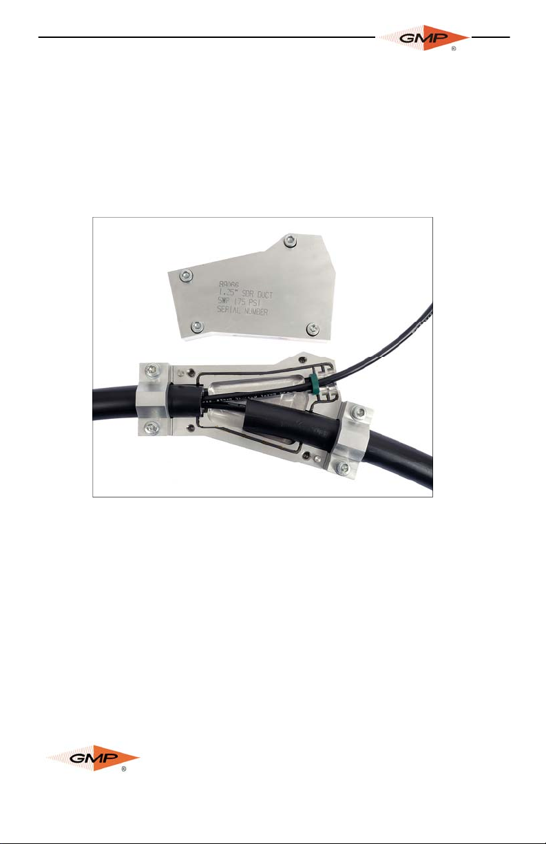
2. GENERAL DESCRIPTION
The GMP Cable Overblowing Junction Box has been designed to
install a new cable or duct-tubes into an existing occupied innerduct (subject to space being available).
The Cable Overblowing Junction Box comprises a heavy duty aluminium base and lid that form a pressurized air chamber into
which one end of an existing occupied innerduct can be attached.
The existing cable can exit the Cable Overblowing Junction Box
through an opening that has 3 cable seal slots, one of which will
house the seal to suit the size of the existing cable. The third
branch is then connected to a GMP Cable Blowing Machine via a
short slave length of innerduct for the installation of the new cable
or tube(s).
LID
EXISTING
CABLE
INNERDUCT CLAMP
COLLET FOR EXISTING
INNERDUCT (OUTGOING)
CABLE
SEAL
OVERBLOWING
JUNCTION BOX
BASE
Page 5 of 16
INNERDUCT CLAMP COLLET
(INCOMING CABLE/
MICRODUCT CONNECTED
TO CABLE BLOWING MACHINE)
General Machine Products Co., Inc.

3. SPECIFICATIONS
Cable Diameter Range: 9 - 20mm
The maximum diameter of a new cable for installation is dependent on the diameter of the existing cable and the duct size.
Duct Size:
Installation Principle:
Max Operating Pressure:
Length:
Width:
Height:
Weight:
Min Flow Acceptance:
1 1/4" SDR
Viscous Drag
175 psi (12 Bar)
12" (305mm)
6" (152mm)
3" (76mm)
9 lbs. (4kg)
250 cfm (7m³/min)
Page 6 of 12
General Machine Products Co., Inc.

4. OPERATING PROCEDURE
IT IS IMPERATIVE THAT ALL PERSONS USING, OPERATING OR
MAINTAINING THE OVERBLOWING CABLE JUNCTION BOX, BLOW-
ING MACHINE, POWER PACK AND AIR COMPRESSOR MUST BE
FULLY TRAINED, COMPETENT AND AUTHORIZED TO DO SO, THEY
MUST ALSO HAVE READ THE ENTIRE OPERATING MANUAL.
GENERAL MACHINE PRODUCTS CO., INC. CANNOT BE HELD RESPONSIBLE FOR MIS-USE OF THIS EQUIPMENT.
1. Ensure that the Cable Blowing Junction Box is clean and free
from debris, sludge, dirt, water and lubricant.
2. Ensure that all the retaining screws and lower clamp collet
screw threads are clean and free from debris, sludge, dirt, water
and lubricant.
3. Ensure that all cord seals are fitted and are in good condition,
replace any damaged or worn seals.
4. Ensure that the innerduct is fully prepared for use.
a. Fully connected
b. Pressure tested
c. Calibrated
d. Cable exit retaining device attached
e. Lubricated
5. Position the Cable Overblowing Junction Box into the manhole,
duct or trench.
6. Remove the lid and open the innerduct clamps (F)(A) , place
the existing innerduct (C) into the innerduct clamp collet and junction box base collet (this is the single position on the Junction
box), ensure the innerduct is fully engaged into the junction box
base.
7. Fit the innerduct clamp (F) and tighten the two retaining cap
screws (H). Do not over tighten the retaining screws.
8. Fit the correct size cable seal (E) to the existing cable (G) and
place into the correct seal housing slot in the junction box base.
Note the seal groove faces inboard with the splits positioned vertically downwards in the base.
9. Locate the innerduct (B) from the cable blowing machine into
cable incoming position, the amount of insertion will depend on the
innerduct and cable / duct tube(s) sizes and must be accessed by
the operator to give a smooth buckle free entry into the existing
Page 7 of 16
General Machine Products Co., Inc.

F
H
I
E
duct, to assist
the incoming
cable / duct it
C
may be beneficial to cut part of
the end of the
innerduct end to
fit around the
existing cable,
fit the innerduct
clamp (A) and
tighten the two
E
X
I
S
T
I
N
G
D
U
C
G
B
A
T
B
LO
W
E
R
D
G
retaining cap
screws (H). Do not over tighten the retaining screws.
10. For installing duct tubes, tube end caps will need to be fitted,
the duct tubes may also need to be pressurized.
11. Apply a smear of silicon grease to the edge of the cable / tube
(s) entry point on the junction box base and lid.
12. The cable blowing machine should be set up ready to install
the new cable/duct-tube(s), (refer to procedure in the cable blowing machine operator and maintenance manual). The cable / ducttube(s) must be fed through the short slave length of innerduct
from the cable blowing machine and into the existing innerduct fed
into the Cable Overblowing Junction Box by approx. 6 - 15’ (2 –
5m).
13. Close the Cable Overblowing Junction Box lid and secure by
tightening all 4 retaining cap screws. Do not over tighten.
14. The system is now ready to begin installing the new cable /
duct tube(s).
15. On completion of the installation it may be necessary to remove the short length slave innerduct with a duct slitter.
16. DO NOT OPEN THE CABLE OVERBLOWING
JUNCTION BOX WHILE UNDER PRESSURE.
Always check that the air pressure gauge on the blowing machine has reduced to zero before opening.
Page 8 of 12
General Machine Products Co., Inc.

5. MAINTENANCE AND SERVICING
The GMP Overblowing Junction Box requires very little maintenance or servicing.
1. Always ensure that the unit is clean and free from debris,
sludge, dirt, water and lubricant.
2. Ensure that all the retaining screws and lower clamp collet
screw threads are clean and free from debris, sludge, dirt, water
and lubricant.
3. Always ensure that all cord seals are in good condition and replace any damaged or worn seals. The cord seals should be cut to
length and glued into the grooves in the junction box housing
upper and lower halves.
4. Always ensure that the cable seals are in good condition and
replace if damaged or worn. For best sealing results the cable seal
should be the smallest size available, for example, for a 16 mm
dia. cable select a cable seal in the range 14-16 mm as opposed
to 16-18 mm diameter.
5. Always ensure that the retaining washers on the innerduct
clamps and lid retaining cap screws are in good condition, they
must prevent the screws from being withdrawn.
6. Always check that the screws are securely tightened.
7. The lid and base should be stored as an assembled unit to en-
sure that parts aren't lost.
Page 9 of 16
General Machine Products Co., Inc.

6. TROUBLESHOOTING GUIDE
CABLE BLOWING MACHINE STOPS SUDDENLY DURING CABLE INSTALLATION
• Maximum hydraulic pressure achieved
• Obstacle in duct installation
• Power Pack out of fuel
• Emergency stop button pressed
• Damaged lead between Power Pack and blowing machine
EXCESSIVE AIR LEAKAGE FROM OVERBLOWING JUNCTION
BOX
• Damaged cord seal
• Cable seals worn, incorrect size, installed wrong way around.
POWER PACK ENGINE DOES NOT STOP AT MAX PRESSURE
• There is a fault with the cable blowing machine, refer to the ca-
ble blowing machine operator and maintenance manual for instructions to rectify the problem.
Page 10 of 12
General Machine Products Co., Inc.

7. SPARES
For spare parts always provide the part number and serial number.
General Machine Products Co.
3111 Old Lincoln Highway, Trevose PA 19053 USA
TEL: +1 215 357 5500
FAX: +1 215 357 6216
E-MAIL: info@GMPtools.com
Website: www.GMPtools.com
Please give as much information as possible to ensure correct
identification and supply of spare parts.
RECOMMENDED SPARES LIST
PART
No
89147 Seal Cord 10’
89588 Sealing Cord Glue 1 Tube
89148 Silicon Grease 1 Tube
33218 Seal 9-10.5mm (1 brown line) 1
33219 Seal 10.5-12mm (2 brown lines) 1
33220 Seal 12-14mm (1 silver line) 1
33221 Seal 14-16mm (2 silver lines) 1
33222 Seal 16-18mm (1 gold line) 1
33223 Seal 18-20mm (2 gold lines) 1
Description
Page 11 of 16
General Machine Products Co., Inc.
Qty
required

GMP • 3111 Old Lincoln Hwy • Trevose, PA 19053 • USA
TEL: +1-215-357-5500 • www.gmptools.com
Page 12 of 12
General Machine Products Co., Inc.
 Loading...