

General Machine Products 89010 User Manual
BREEZE MICRO CABLE BLOWING MACHINE
OPERATION & MAINTENANCE
89010 (BREEZE) – USA
CABLE BLOWING MACHINE
Copyright 2009 by General Machine Products Co., Inc
QC Final Inspection by:_________________________ Date:__________________
Unit Serial Number:__________________
Build Date:__________________
All rights reserved. No part of this publication may be copied, reproduced or transmitted in any form
whatsoever without the written permission of General Machine Products Co., Inc.
GMP • 3111 Old Lincoln Hwy • Trevose, PA 19053 • USA
TEL: +1-215-357-5500 • FAX: +1-215-357-6216 • EMAIL: info@gmptools.com
Page 1 of 43
General Machine Products Co., Inc.
Dec 18 2013 USA Ver 11
Manual Part Number 32384

REVISION HISTORY
Rel.no Date Details Author
01 08.27.03 Original issue A. Sibun
02 09.19.07 US Version 1 A. Konschak
03 07.05.07 US Version 2 A. Konschak
04 04.30.08 US Version 3 A. Konschak
05 05.25.09 US Version 4 A. Konschak
06 11.23.09 US Version 5 - updated CUB5 Matrix A Konschak
07 06.09.10 US Version 6 - update Appendix 1 A Konschak
08 03.29.11 US Version 7 - update blown fiber page 24 A Konschak
09 05.18.11 US Version 8 - add guide positioning warning A Konschak
10 10.03.12 US Version 9 - add 14 mm tube kit A Konschak
11 06.23.13 US Version 10 - A Konschak
12 12.18.13 US Version 11 - Various minor updates A Konschak
Page 2 of 43
General Machine Products Co., Inc.

CONTENTS
1. Safety Instructions
2. Critical Points
3. General Description
4. Specification
5. Operating procedures
6. Maintenance
7. Procedure for changing inserts in the tube clamp
8. Procedure for changing inserts in the air box
9. Procedure for changing inserts in the infeed guide
10. Procedure for re-positioning the measuring system fixed roller
11. Procedure for replacing the air box housing seal
12. Procedure for changing the air box infeed guide
13. Procedure for changing the drive rollers
14. Procedure for conversion to blow 12 count (1.6) fiber
15. Monthly Service – check list
16. Service History Record
17. Tube integrity and Lubrication
18. Recommended Spares List
APPENDICES
Appendix 1 Cable and tube insert selection chart.
Appendix 2 Recommended torque control potentiometer settings
Appendix 3 Programming the speed/distance measuring device.
GMP Limited Warranty
Page 3 of 43
General Machine Products Co., Inc.

1. SAFETY INSTRUCTIONS
This Equipment should be used only by personnel who have been given the appropriate training and who are competent to use it.
These instructions are to be made available to operators of this equipment at all times.
Failure to observe these safety instructions could result in serious personal injury and/
or property damage.
WORK AREA AND GENERAL SAFETY
1. Read and understand the operation and maintenance manual supplied with this equip-
ment. Keep it in a convenient place for future reference.
2. Keep children and untrained personnel away from this equipment while in operation.
3. Keep all guards and safety devices in place. Do not operate this equipment with guards
removed or damaged.
4. Keep hands, feet and loose clothing away from moving parts, especially at cable entry
points.
5. Always stop the machine and isolate compressed air and electrical services to carry out
lubrication and servicing.
6. Check machine before starting for worn or damaged parts. Check for signs of loose nuts
and bolts etc.
7. If machine is left unattended, insure that unauthorized use is prevented.
8. Never leave the machine unattended while in use.
9. Consider the use of safety barriers, especially when used in public places, observe all
statutory requirements for working environments.
10. Beware of pinch points involved with rotating components.
11. Beware of hot surfaces, machine uses compressed air.
12. When operating machine always wear appropriate safety clothing, hearing protection, eye
protection, hard hat, safety shoes and leather gloves, machine operates with compressed
air at up to 218 psi.
13. Prior to installation insure the tube route is connected properly.
14. Beware of exposed electrical contacts. Do not touch, or allow metal objects to come into
contact.
15. Machine may cause additional fire hazard if involved in an existing fire due to com-
pressed air.
Page 4 of 43
General Machine Products Co., Inc.

16. No personnel are to be in manholes or ducts when the Cable Blowing Machine is being
operated.
17. The machine must be operated on firm ground.
18. Stay clear of cables or lines under tension.
19. Stay clear of pressurized air line and tube.
20. Only use the machine for its intended purpose. Do not use the roller drive without the air
chamber to push or to retrieve cable or blow air in the far end of tube to help cable
recovery.
21. Do not place cable drum too close to the Cable Blowing Machine.
22. Do not tamper with pressure relief valves or pressure reducing valves.
23. The compressed air supply must not be allowed to enter the air chamber or tube before
the drive rollers have been closed on to the cable. Do not turn the air on until a reasonable
length of cable (165 ft) has been installed into the tube.
24. Ensure the cable drum rotates freely on its stand, the cable should leave from the top of
the drum.
25. The cable should enter the machine in a clean and dry condition. In damp, dusty atmos-
pheres, the cable should be cleaned continuously as it enters the machine.
FAILURE TO DO SO MAY RESULT IN PERSONAL INJURY, AS THE CABLE
COULD BE EJECTED FROM THE CABLE BLOWING MACHINE WITH HIGH
FORCE AND VELOCITY.
Page 5 of 43
General Machine Products Co., Inc.

GENERAL PNEUMATIC SAFETY INSTRUCTIONS
The GMP Fiber Optical Cable Blowing Machine is a pneumatic device, using pressurized air
to project cable at high velocities. Please observe the following precautions when operating
the Cable Blowing Machine:
1. Compressed air can cause flying debris. This could cause personal injury. Always wear
personal protective equipment.
2. Insure no personnel are in the manhole at the far end of the cable run. Severe personal
injury may result.
3. Never open the air chamber when pressurized.
4. Only authorized, fully trained personnel should operate the air compressor.
GENERAL ELECTRICAL SAFETY INSTRUCTIONS
The machine has electronic and electrical power and control circuits. Electric shock hazards
exist that could result in severe personal injury. Observe the following precautions to avoid
electrical hazards:
1. Do not operate in water.
2. Do not expose the machine to rain.
3. Do not remove cover of electronic control assembly. There are no user serviceable parts
inside.
4. Refer servicing to qualified service personnel.
Page 6 of 43
General Machine Products Co., Inc.

2. Critical points that dramatically affect the operation of the cable blowing
machine.
Pressure on the cable (Position of the close arm assy) should be set as per the instruc-
tions.
Rollers to be closed at all times when cable is installed into machine.
Cord seals in air chamber correctly fitted to provide good sealing.
Correct cable seal fitted.
Tube fully connected and pressure-tested.
Tube connecting fittings are suitable for operating at 220 PSI air pressure.
Tube clamp securely tightened.
Compressor capacity 220 PSI and suitable for size of tube being used.
Cable drum must be located directly behind and in line with the blowing machine.
Air chamber, drive rollers, cable guides, must be clean and free from debris, sludge, dirt,
water and lubricant.
The cable must be hand guided into the blowing machine through a dry clean cloth by the
operator wearing work gloves.
Ensure the compressed air supply is not applied to the cable until approximately 165 ft of
cable have been installed or the motor begins to labor.
Page 7 of 43
General Machine Products Co., Inc.

DISCLAIMER
General Machine Products Co., Inc and CBS Products Ltd. takes care in the design of its
products to insure that the cable is protected during installation. Due to the variety and different methods of cable manufacture the responsibility of checking the cable compatibility with
the equipment lies with the user. Therefore, GMP nor CBS Products Ltd. can accept liability
for any damage to the cable.
Page 8 of 43
General Machine Products Co., Inc.
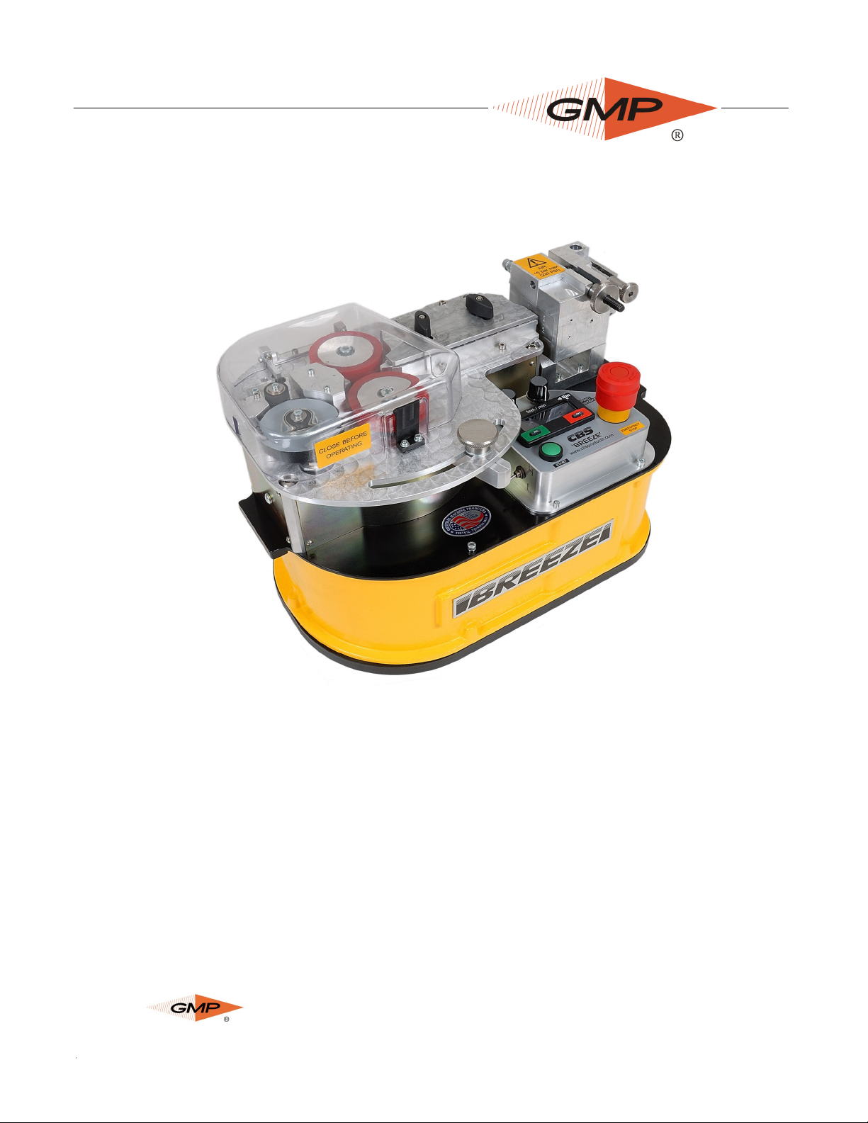
3. GENERAL DESCRIPTION
The Breeze Micro Cable Blowing Machine is designed to install small diameter cable into
micro tubes.
The Breeze uses a DC motor and reduction gearing to
drive a pair of compliant rollers that are both driven.
The rollers are covered with a soft synthetic coating to
prevent damage to the cable. Different coatings are
available depending on the surface texture of the cable
being installed. The rollers may be changed quickly using one simple tool.
The pressure the rollers apply to the cable is adjustable.
The torque applied to the cable by the rollers can be
adjusted to help prevent cable buckling.
A full range of accessories is available to allow the machine to handle a wide range of cables
and micro tubes.
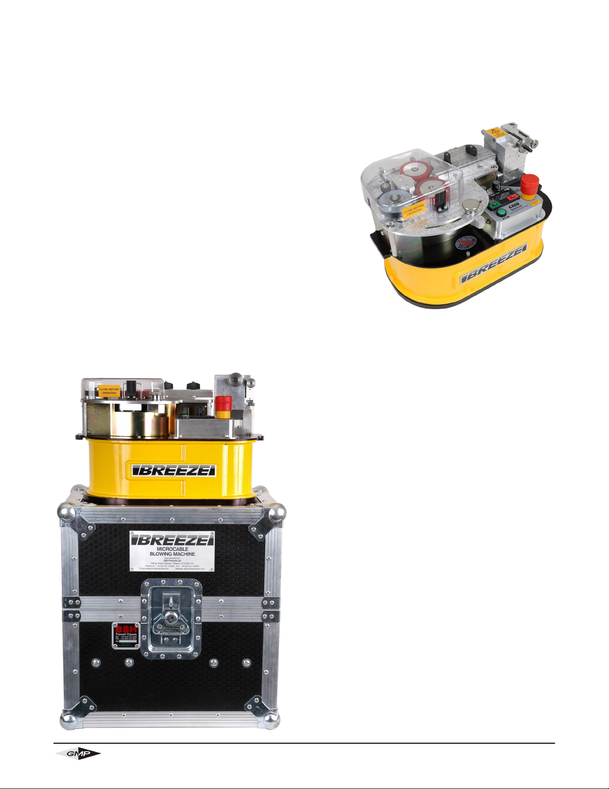
As pictured, the Breeze may be placed on the
ground or on a support to bring the cable to a
suitable height. The Breeze is supplied with a
reinforced case which will protect the machine
from damage during transit and can also be used
as a support for the machine when installing cable.
Page 9 of 43
General Machine Products Co., Inc.

4. SPECIFICATIONS
Cable size: 1.0 to 8.5 mm1 0.1” to 0.335”
Tube size: (OD) 4 to 18 mm 0.158” to 0.709”
Cable speed: 0-50m/min. 0-165 ft/min
Maximum pushing force: 16 Kg. 35 lbs.
Maximum air pressure: 15 bar. 220 psi.
Power requirements:
115/220V ac 50/60 Hz
Switchable
Gripping force, (rollers onto cable): 1-40 Kg 1-88 lb.
Weight 23Kg approx. 50 lbs. approx.
Dimensions (ht x length x width) 250mm x 390mm x 270mm 10” x 15 3/8” x 10 5/8”
1
1 - 2.5 mm blown fiber available with add-on kit
Page 10 of 43
General Machine Products Co., Inc.
5. OPERATING PROCEDURE
IT IS IMPERATIVE THAT ALL PERSONS USING, OPERATING OR MAINTAINING THIS
CABLE BLOWING MACHINE:
● HAVE RECEIVED COMPREHENSIVE TRAINING IN THE USE OF THIS MACHINE.
● ARE COMPETENT AND AUTHORIZED TO USE IT AND HAVE READ AND UNDER-
STAND THIS MANUAL.
GENERAL MACHINE PRODUCTS CO., INC OR CBS PRODUCTS LTD. CANNOT BE
HELD RESPONSIBLE FOR MISUSE OF THIS EQUIPMENT.
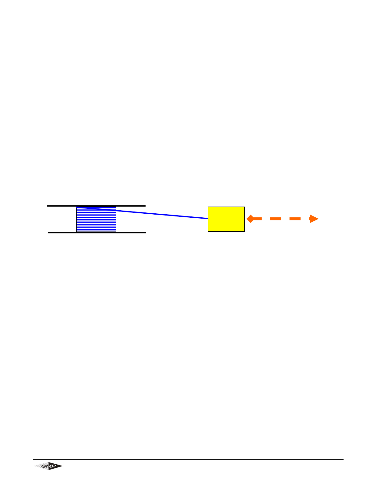
Set up for installing cable with the machine mounted above ground:
1. Position the machine in line with the route of the duct.
2. Position the cable drum behind the machine and in line with the machine.
See sketch below (this shows a plan view of the recommended set up).
Tube route
Cable Drum
3. Ensure the machine is secure (either on its own stand or a separate suitable stand).
4. Ensure the machine is fitted with the appropriate guides and collets to suit the cable being
installed and the tubes into which the cable is to be installed. (See appendix 1 for details
of interchangeable parts).
To set the machine up to install cable it will be necessary to:
1. Fit the tube into which the cable is to be installed into the tube clamp and air box .
2. Fit the cable through the machine.
3. Connect the air supply to the machine.
4. Connect the electrical power input to the machine.
Breeze Machine
Page 11 of 43
General Machine Products Co., Inc.
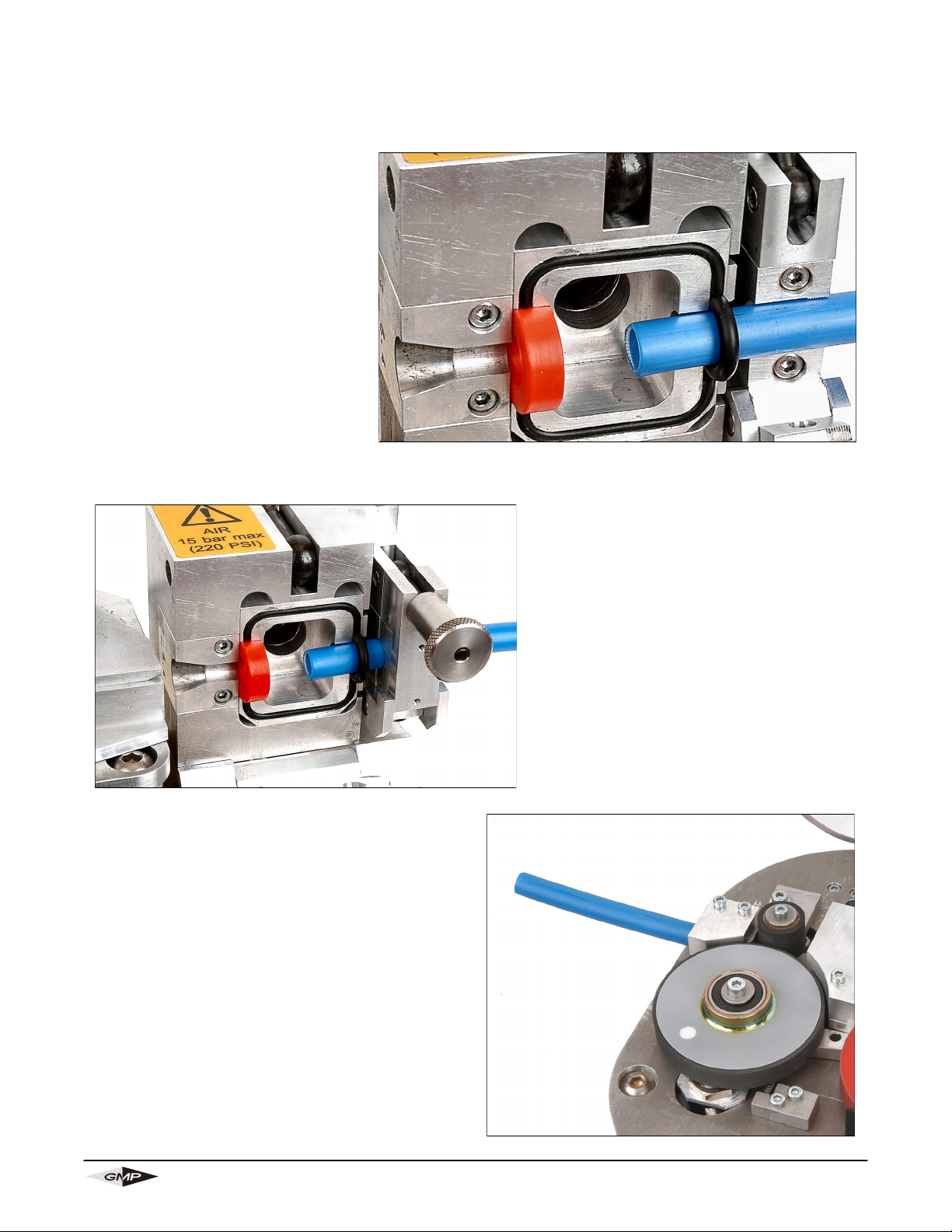
Fit the tube into which the cable is to be installed into the air box and tube
clamp.
Slide a tube seal, sized for the
tubing you are using, over the end
of the tube.
Fit the tube about half way into
the air box housing as shown in
the photo, positioning the tube
seal so that it sits against the seal
face.
Positioning the tube further into
the air box helps prevent the bucking of smaller fiber.
Cut and split a short length of tube to use as
an in-feed guide (this tube need only be split if
blowing a cable mid-span; sometimes called
series blowing). This should be inserted in the
in-feed guide clamp. (In order to give the best
support for the incoming cable, it may be helpful if the end of the tube is cut off at an angle
to match the angle on the in-feed guide
clamp. This short length of tube will act as a
guide to feed the incoming cable into the
measuring system and into the in-feed guide.
If necessary a length of smaller diameter tube
may be fitted inside this tube to act as a guide
for smaller diameter cables.
Once the tube has been positioned, the tube clamp may be
closed. Securely tighten clamp
with swing bolt. The tube is now
secure.
Page 12 of 43
General Machine Products Co., Inc.
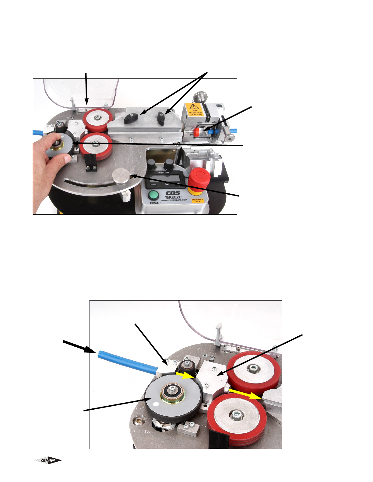
Fit the cable through the machine.
Raise the clear cover to
expose the roller drive.
Loosen the thumb nuts and retract the cable guide top plate.
Loosen the thumb
nut and open the
seal housing.
Hold back the measuring
wheel, so that the spring is
compressed.
Move the drive roller close
assembly to the far right to
fully open the rollers.
It is now possible to insert the cable in the machine.
Pass the cable through the tube in the in-feed guide clamp, on through the in-feed guide assembly and through the gap between the drive rollers. Place the cable in the groove in the cable guide set. Select the appropriate split cable seal (see appendix 1) and position it around
the cable. Press the cable seal into the groove in the seal housing, simultaneously placing the
cable in the seal guide half and insert the cable in the tube entry.
The cable is now positioned in the machine.
Measuring
Wheel
In-feed
Guide
Clamp
Page 13 of 43
In-feed
Guide
Assembly
General Machine Products Co., Inc.
 Loading...