

POWERED DUCT ROD PUSHER
OPERATION & MAINTENANCE
89004 – USA
POWERED DUCT ROD PUSHER
Copyright 2008 by General Machine Products Co., Inc
QC Final Inspection by:_________________________ Date:__________________
Unit Serial Number:__________________
Build Date:__________________
All rights reserved. No part of this publication may be copied, reproduced or transmitted in any form
whatsoever without the written permission of
GMP • 3111 Old Lincoln Hwy • Trevose, PA 19053 • USA
TEL: +1-215-357-5500 • FAX: +1-215-357-6216 • EMAIL: info@gmptools.com
General Machine Products Co., Inc.
Page 1 of 40
General Machine Products Co., Inc.
August 29 2009 USA Ver 3
Manual P/N 32297

REVISION HISTORY
Rev # Date Details Author
01 07.27.05 Original issue A. Sibun
02 10.16.08 US Version 1 A. Konschak
03 05.26.09 US Version 2 A. Konschak
04 08.29.09 US Version 3 A. Konschak
Page 2 of 40
General Machine Products Co., Inc.

CONTENTS
1. Safety Instructions
2. Critical Points
3. General Description
4. Specification
5. Operating procedures
6. Maintenance
7. Procedure for Replacement of Chain Drives
8. Procedure for Replacement of sub-duct clamp collets
9. Procedure for Adjusting the sub duct clamp and collet type rod infeed guide assembly height
10. Monthly Service – Check List
11. Service History Record
12. Troubleshooting Guide
13. Recommended Spares List
APPENDICES
Appendix 1 Layout of Rod Pushing Machine
Appendix 2 Drawing – Rod Pushing Machine
Appendix 3 Hydraulic & Electrical Panel Layout
Appendix 4
Warranty
Counter programming parameters
Page 3 of 40
General Machine Products Co., Inc.

INTRODUCTION
Founded by engineer George M. Pfundt in 1936, GMP started operations in a downtown Philadelphia building as a specialty machine shop doing work for the local Bell Telephone company and
for the electric utility company. GMP expanded to a production
shop after landing a contract
with Western Electric Company and, subsequently, forming a close relationship with Bell Telephone Laboratories in Murray
Hill, N.J., which enabled it to manufacture prototypes of products for experimental use within the
Bell System.
Having outgrown the original factory building, the
company built a 100,000 square foot plant in
Trevose, PA (a Philadelphia suburb) and moved
there in 1957. Today GMP is recognized as a premier worldwide supplier of specialty tools and equipment for the outside plant marketplace. The company's products are known for their robust design and durability to withstand many years of frequent use.
Page 4 of 40
General Machine Products Co., Inc.
1. SAFETY INSTRUCTIONS
This Equipment should be used only by personnel who have been given the appropriate training and who are competent to use it.
These instructions are to be made available to operators of this equipment at all times.
Failure to observe these safety instructions could result in serious personal injury and/
or property damage.
CAUTION:
This machine is designed to work with one piece, continuous rod with no breaks. Rods that
have been repaired and have a coupling at any point along its length, cannot be used since
!
the coupling cannot safely pass through the Duct Rod Pusher.
FAILURE TO DO SO MAY RESULT IN PERSONAL INJURY
WORK AREA AND GENERAL SAFETY
1. Read and understand the operation and maintenance manual supplied with this equip-
ment. Keep it in a convenient place for future reference.
2. Keep children and untrained personnel away from this equipment while in operation.
3. Keep all guards and safety devices in place. Do not operate this equipment with guards
removed or damaged.
4. Keep hands, feet and loose clothing away from moving parts, especially at cable entry
points.
5. Always stop the machine and isolate hydraulic and electrical services to carry out lubrica-
tion and servicing.
6. Check machine before starting for worn or damaged parts. Check for signs of loose nuts
and bolts etc.
7. If machine is left unattended, insure that unauthorized use is prevented.
8. Never leave the machine unattended while in use.
9. Consider the use of safety barriers, especially when used in public places, observe all
statutory requirements for working environments.
10. Beware of pinch points involved with rotating components.
11. Beware of hot surfaces, machine uses hydraulics.
12.
When operating machine always wear eye protection, hard hat, safety shoes and leather
gloves, machine operates with hydraulic oil at 2030 psi.
Page 5 of 40
General Machine Products Co., Inc.

13. Some component and assembly parts are in excess of 55 lbs. (25kg) . When lifting care must
be taken, insure sufficient man power/lifting gear is available, to prevent personal injury and
damage to the machine.
Beware of exposed electrical contacts. Do not touch, or allow
metal objects to come into contact.
14.
Prior to installation insure the sub-duct route is connected properly.
15. Beware of exposed electrical contacts. Do not touch. Or allow metal objects to come into
contact. Waste hydraulic oils are to be disposed of via an environmentally acceptable
method.
16. Wear hearing protection when noise level are above acceptable limits. To reduce noise,
position Power Pack away from user.
17. Machine may cause additional fire hazard if involved in an existing fire due to hydraulic
oils.
18. No personnel are to be in manholes or ducts when the duct rod pusher is in operation.
19. The machine must be operated on firm ground.
20. Stay clear of rods or lines under tension.
21. Only use the machine for its intended purpose.
22. Do not place duct rod carrier too close to the powered duct rodder.
23. Do not tamper with pressure relief valves or pressure reducing valves.
24. Never operate the rod pushing machine with the electronic control panel immersed in wa-
ter.
25. To prevent damage to the hydraulic hoses and the emergency stop cable never leave
them on the ground when not in use.
Page 6 of 40
General Machine Products Co., Inc.

GENERAL HYDRAULICS SAFETY INSTRUCTIONS
Escaping fluids under pressure can penetrate the skin and cause serious personal injury. Observe the following precautions to avoid hydraulic hazards: -
1. Insure all hydraulic connections are securely tightened before operating the machine.
2.
Check for leaks with a piece of cardboard. Do not use your hands!
3. Do not exceed working pressure of hydraulic hoses.
4. Visually inspect hoses regularly and replace if damaged.
GENERAL ELECTRICAL SAFETY INSTRUCTIONS
The machine has electronic and electrical power and control circuits. Electric shock hazards
exist that could result in severe personal injury. Observe the following precautions to avoid
electrical hazards:
1. Do not operate in water.
2. Do not expose the machine to rain.
3. Do not remove cover of electronic control assembly.
There are no user serviceable parts inside.
4. Refer servicing to qualified service personnel.
Page 7 of 40
General Machine Products Co., Inc.

2. CRITICAL POINTS THAT DRAMATICALLY AFFECT THE
OPERATION OF THE ROD PUSHING MACHINE
a. Two (2) turns on the rod clamping screw.
b. Tractor drive to be closed at all times when rod is installed into machine.
c. Sub-Duct clamp height adjustment correctly set.
d. Rod in-feed bracket height adjustment correctly set.
e. Sub-duct fully connected.
f. Rod drum must be located directly behind and in line with the pushing machine.
g. Sub-duct clamp, tractor drive belts/chains, housing framed and rod guide intake assembly must be
clean and free from debris, sludge, dirt, water and lubricant. (Each time the pushing machine is
used.)
h. The hydraulic pressure should be between 290-580 PSI at the start of an installation. If greater do
not proceed. Check rod clamping screw setting, sub-duct, rod, rod collet sizes, sub-duct clamp/infeed guide height setting. Rectify before re-commencing the installation.
i. Lubricate the drive chains before use.
j. Do not repeatedly press the on/off button on the length/speed readout. This may result in irrelevant
digits being displayed or may alter the program. Always fit the hydraulic hose dust caps when the
hose is not in use, clean and check the quick release couplings before use.
NOTE:
This machine is primarily designed to work with the GMP 1/2 Duct Rodder. Other manufacturer’s Duct
Rodders may be able to be modified to work. Please contact the factory for details.
Page 8 of 40
General Machine Products Co., Inc.

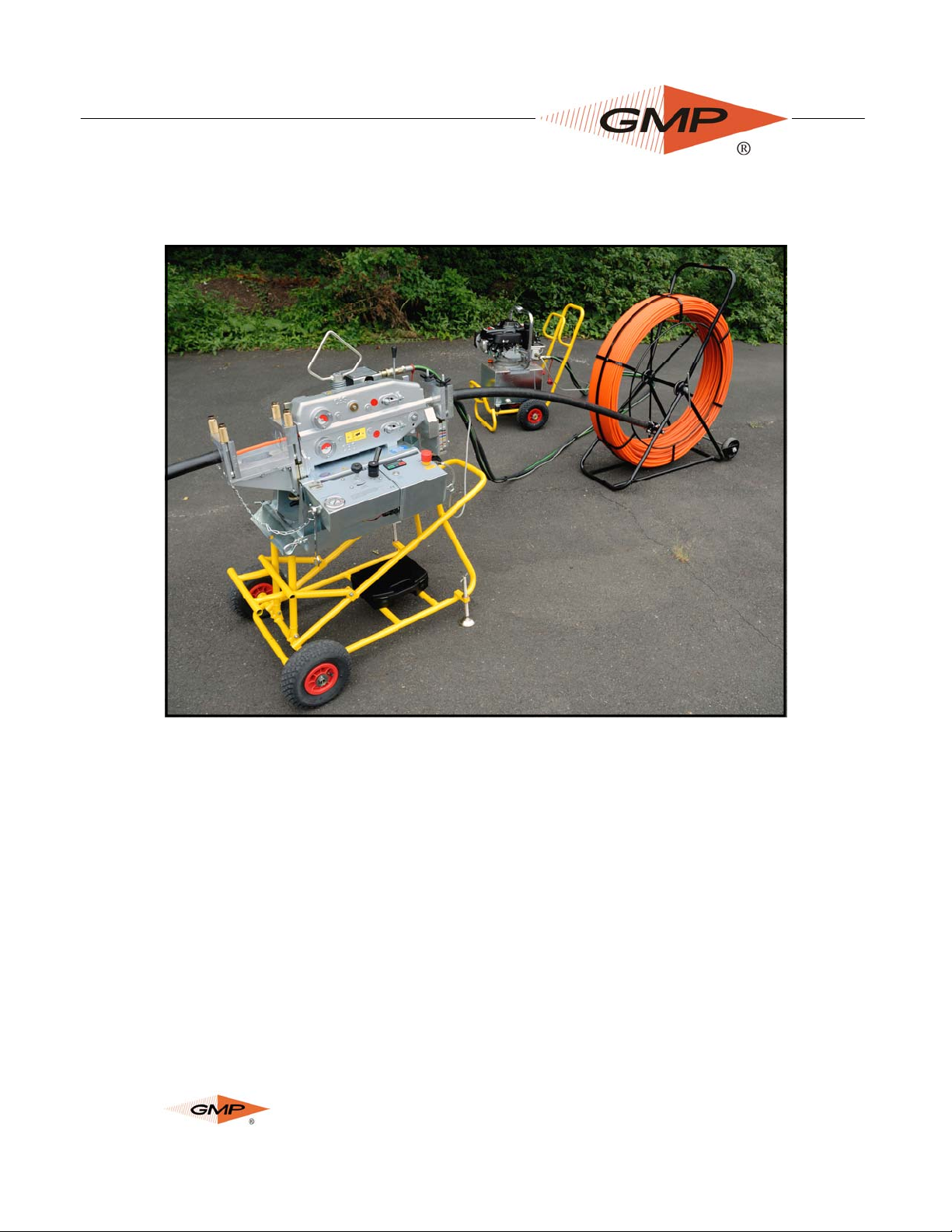
3. GENERAL DESCRIPTION
The Duct Rod Pushing machine has been designed to provide an effective and safe method
of rod installation and removal. The system installs rod of 1/2” overall diameter at up to 130 ft/
min into pre-installed sub-ducts.
The machine is protected by preset pressure relief valve and preset pressure sensor.
The hydraulically powered rod feed system controls the rod. The electronic control system
displays speed, distance, direction and the preset pressure sensor provides automatic protection against duct obstruction.
The system comes mounted on a sturdy anti-corrosion, height adjustable, wheeled, tubular
steel trolley unit for ease of site maneuverability, and is powered by a hydraulic supply system
operating at 2030 psi x 5.3 gallons/min.
The rod pushing unit can be easily detached from the trolley and located in a trench or manhole (depending on the size of the manhole).
The unit is supplied with two (2) x hydraulic hoses x 23 feet and a 26 foot long emergency
stop lead.
Page 9 of 40
General Machine Products Co., Inc.

FEATURES
Fully labeled control panel containing:
▪ Power ON/OFF button
▪ Emergency Stop Button
▪ Installation speed and direction readout in m/min or ft/min through a separate calibration
▪ Length counter tracking in feet or meters through a separate calibration
▪ Hydraulic pressure display gauge
▪ Hydraulic on/off control valve
▪ Emergency stop connection socket
▪ Adjustable speed control for drive belts
▪ Battery Charging Connection
Control panels are anti corrosion treated and may be removed independently for repair work.
CHASSIS
▪ Front mounted wheels for ease of maneuverability
▪ Light painted tubular steel frame
▪ Adjustable frame allowing unit to be tilted at 20º to manhole
▪ Adjustable legs for uneven terrain
▪ Detachable rod pushing unit for trench / manhole location
ROD FEEDER
▪ Manufactured from cast aluminum
▪ Hydraulically powered
▪ Unit lifts and splits to allow insertion of rod between drive belts
▪ Drive belts are polyurethane and molded to unit ensuring long life between replacements.
▪ Lifting hook built into adjustable jack screw to allow unit level lift.
▪ Belt tension can be set by means of adjustable chain drive tensioners fitted to the side of
the unit
▪ System relief valve factory set to 1500 psi.
Page 10 of 40
General Machine Products Co., Inc.

4. SPECIFICATIONS
OPERATION CAPACITIES
Pushing Force
Pushing Speed
Rod Size
Sub-Duct Size
HYDRAULIC DRIVE SYSTEM
Operating Pressure
Flow
Pressure Switch Setting
Relief Valve Setting
Initial starting pressure
ELECTRONIC CONTROL SYSTEM
0-300 lbs. (0 - 136 kg)
0-130 ft/min (0 - 40m/m)
1/2” (12.7mm)
1-1/4 SDR
2030 psi (max) (110 Bar)
5.3 gallons/min (recommended)
1450 psi (100 Bar)
1500 psi (103 Bar)
290-580 psi (20-40 Bar) (if greater the set-up
needs checking)
Power requirements:
Fuse Rating
DIMENSION AND WEIGHTS
Height
Length
Width
Weight
Tire Size
Tire Pressure
Drive Chain Lubrication
12 Volts DC
3.15 amp (Slow-Blow)
49”
42”
28”
210 lbs.
3.00-4/260x85
25 psi (1.72 Bar)
Metaflux 70-88 Chain Spray
Page 11 of 40
General Machine Products Co., Inc.
5. OPERATING PROCEDURE
It is imperative that all persons using, operation or maintaining this cable blowing machine:
Have received comprehensive training in the use of this machine.
Are competent and authorized to use it and have read and understand this manual.
General Machine Products Co., Inc. cannot be held responsible for misuse of this equipment.
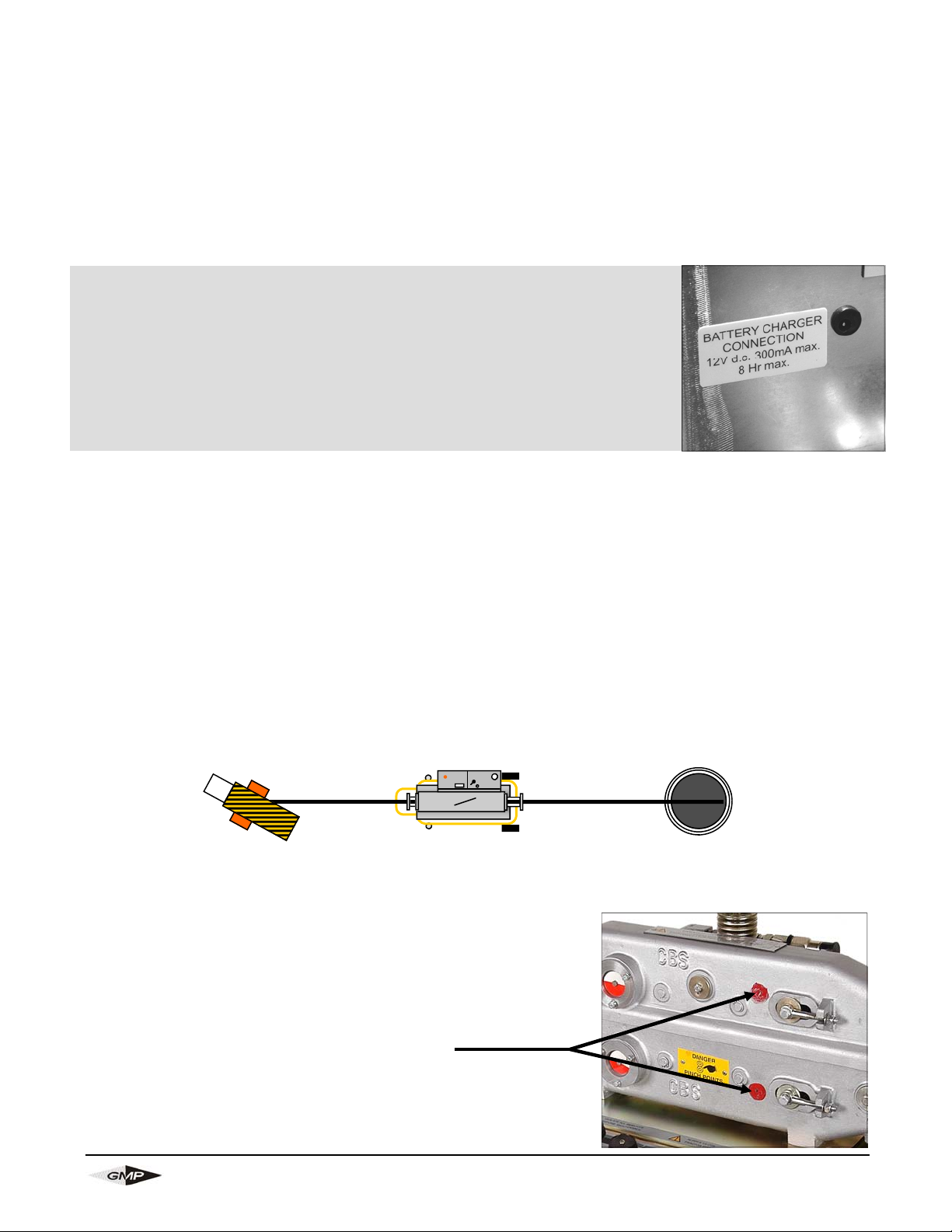
Charging the 12 volt battery before use:
Plug in the supplied battery charger in the charging jack found on the
right of the control panel. Initially charge the battery for 8 hours before
use (to approximately 13 volts). Continuous charging of the battery with
your charger will reduce the life of the battery. Remove the charger
when charging is complete. When voltage dips to 12 volts, recharge the
battery. Optimize battery life by turning off the display when not in use.
1. Position the Rod Pushing Machine in a suitable position in line with the proposed sub-duct.
2. Adjust the mounting frame to the desired height and angle by means of the front frame supports. Withdraw the front ‘R’ clip and retaining pin while supporting the weight of the rod
pushing unit. Raise or lower the pushing unit and locate onto the support bar for the desired
position. Refit the retaining pin and ‘R’ clip. Alternatively the pushing unit may be detached
from the trolley frame by withdrawing both ‘R’ clips and retaining pins, while supporting the
weight of the pushing unit.
3. Stabilize the frame on uneven ground by adjusting the height on the pivoting feet at the rear
of the unit and locking in position.
NOTE: CARE SHOULD BE TAKEN WHEN WHEELING THE TROLLEY AROUND NOT TO
CATCH THE ADJUSTABLE FEET PADS ON CURBS OR BOULDERS, THIS MAY DAMAGE THE PIVOTING FOOT.
4. Position Duct Rod approximately 5’ behind the Duct Rod Pusher at about a 35° angle.
Duct Rod
5. Insure the battery is fully charged before commencement of installation.
6. Open tractor drive.
CLEAN ANY DEBRIS, SLUDGE, DIRT, WATER, LUBRICANT,
ETC, FROM FRAME HOUSINGS AND ROD INTAKE GUIDE
BRACKET ASSEMBLY EACH TIME BEFORE USE.
LUBRICATE BOTH CHAINS BEFORE USE.
CLEAN BOTH TRACTOR DRIVE BELTS BEFORE USE.
5ft 1 1/4” Duct 1 1/4” Duct
Duct Rod Pusher
Lubrication Points
Page 12 of 40
General Machine Products Co., Inc.

7. Open tractor drive enough to feed the
duct rod through the pusher.
TIP:
If the duct that is to be rodded is larger
than 1 1/4”, insert a piece of 1 1/4 subduct from the out-feed of the Duct Rodder into the larger duct causing the
smaller duct to act like a feeder.
Tie off the small duct to a ladder or some
other permanent fixture if possible. This
prevents the sub-duct from kicking back
should the duct rod encounter and obstruction.
8. Place sub-duct from the manhole into
out-feed sub-duct clamp and tighten with
3/4” wrench (provided).
9. Take a 5’ piece (approx) of 1-1/4 subduct and lay it into the opened infeed
sub-duct clamp. Feed the rod thru the
duct so that it’s about a foot into the
duct rodder, ensuring that the connector on the end of the rod is past
the infeed clamp. Now tighten the
clamp on the duct.
10. Clamp the other end of the 1 1/4” subduct into the supplied duct rodder carriage clamp.
Page 13 of 40
General Machine Products Co., Inc.

11. Feed the duct rod through the
pusher and into the sub-duct that’s
placed in the manhole.
12. The correct rod clamping force is
vital to the performance of the machine. It should be set as follows:
Tighten the handle with one hand
rotating the clamp washers with
the other. The clamp washers will
turn easily until the handle begins
to clamp them. When the clamp
washers become almost impossible to turn with one hand, this is
the start point for the clamp force
setting. Continue to turn the handle
a further 2 full turns. This will insure the correct force.
13. Connect the hydraulic hoses
and emergency stop connector to
the duct rod pusher taking note
that the connector is female on the
pusher side and male on the power
pack side.
Page 14 of 40
General Machine Products Co., Inc.

14. Insure that the hydraulic control
lever is in the “OFF” position and
the speed control knob is in the
“Min” position (fully rotated
counter-clockwise).
15. The emergency stop button is set
to on (upper most position). If not
set, twist counter-clockwise to reset.
16. Start the engine on the power
pack. Insure that you have
enough fuel for the duration of the
pushing operation.
17. Select desired pushing direction
from the valve to the rear of the
machine. Direction is indicated.
Page 15 of 40
General Machine Products Co., Inc.

18. Turn the Hydraulic lever valve to
the “ON” position.
19. Turn on the digital display by pressing the “power on/off” button. Allow approx. five
(5) seconds for the display to appear. Pressing SEL toggles between installation distance (ft) and speed (ft/min) (designated by R). Pressing RST will reset the distance
reading to zero (0).
20. Turn the speed control valve
clockwise (towards ‘max’) until the
desired speed (130 ft/min max) is
achieved.
21. Continue to install rod into sub-duct. The operator wearing work gloves should insure the
rod enters the machine without debris. Care must be taken to avoid injury by clothing or
fingers being dragged into the machine. Failure to do so may result in damage to the rod
form the drive belts and/or jamming of the rod.
24. To prevent dirt from entering the
machine when pulling back the
rod, use a felt wiper at the subduct out feed side and clamp it
tightly to the rod as shown in
photo.
23. On completion screw the speed
control knob to the min to stop the
machine, (counter clockwise),
press the reset button and select
neutral from the direction control
valve.
Page 16 of 40
General Machine Products Co., Inc.

24. IF THE PUSHING MACHINE STOPS SUDDENLY
If the rod pushing machine stops suddenly during the pushing operation it is likely that
the pressure switch has tripped, the probable reasons for this are: A) The rod has become jammed, has hit an obstruction in the duct or the rod pushing
operation has reached its maximum capability.
B) The power pack has developed a problem or has run out of fuel.
IN THE EVENT OF AN EMERGENCY
1. Push the emergency stop push button.
Turn the speed control knob to “Min”
3.
position (fully counter clockwise)
2. Turn the hydraulic valve to the ‘off’ position.
4. Press the on/off button (to turn off the
electric’s off, if required).
Page 17 of 40
General Machine Products Co., Inc.

TO RESTART
1. Take machine out of emergency stop by
turning the red button counter clock wise.
Restart the hydraulic power pack.
2. Turn the hydraulic on/off valve to “on’”
position.
3. Turn on the digital display by pressing
the “power on/off” button. (If the electric’s
have been switched off)
4. Turn the speed control valve clockwise
until the desired speed (up to 130 ft/min
max) is achieved.
Page 18 of 40
General Machine Products Co., Inc.

6. MAINTENANCE
To insure reliable service from your Rod Pushing Machine, we recommend the unit be completely serviced every 6 months.
TRACTOR DRIVE
Inspect the chain drive blocks for wear each week.
CHECK the chain tension weekly and adjust if necessary with the two
external adjustment screws (do not over tension). The chain should
slightly lift off the chain guides, when pulled at the center by finger.
THE CHAIN SHOULD BE LUBRICATED EACH TIME USED by application of Metaflux
spray grease 70-88. This is achieved by running the rod pushing machine at about 130ft/min
without any rod and carefully inserting the spray tube from the canister into the holes on the
operator side of the aluminum drive castings (2). The spray tube should be carefully inserted
until the chain can just be felt and then withdrawn about 3/4 – 1” and spraying for approximately 1 second.
DO NOT OVER LUBRICATE, AS THIS MAY LEAD TO THE DRIVE BELTS BEING
CONTAMINATED WITH LUBRICANT.
If contamination does result, wipe the belts clean thoroughly before attempting any pushing
operation. (This is based on normal use where the chains are not exposed to excessive
contamination).
Bottom frame chain lubrication
point
Page 19 of 40
Top frame chain lubrication point
General Machine Products Co., Inc.

GENERAL
The machine should be stored under cover when not in use. The machine should be wiped
clean after each time used.
ALWAYS insure that the service battery and spare battery (if available) are fully charged,
before this rod-pushing machine is to be used. The machine uses a conventional lead – acid
batterie, this may be charged using the supplied battery charger for a maximum of 8 hours.
CHECK the tire pressures and tire condition weekly. Oil the frame pivot points and lubricate
the oilite bearings with light machine oil every month. Apply grease to the jacking screw
thread each month clean out any dirt/debris from the rod-measuring wheel, measuring disc
and speed pick up probe.
Oil sub duct clamp adjusting screw and rod infeed guide adjusting screw monthly.
Grease axles every month. Check function of electrical panel each time.
SERVICE CONNECTIONS
CHECK the condition of the hydraulic hoses each time used and replace if worn or damaged.
CHECK the condition of the emergency stop cable each time used and replace if worn or
damaged.
Page 20 of 40
General Machine Products Co., Inc.

6.1. MAINTENANCE SCHEDULE
PROCEDURE DAILY WEEKLY MONTHLY
Clean all assemblies and components thoroughly
Inspect hydraulic hoses for leaks and cracks
Inspect fasteners, screws and retaining pins / wire
Check / adjust chain tension
Check tractor drive pads for wear / damage
Tire pressure / condition
Check condition of emergency stop lead
Clean rod infeed guide bracket and collets
Clean measuring wheel measuring disc and speed pick
up probe
Function of electronic panel
Oil the frame pivot points
Grease jacking screw thread
Oil sub duct clamp adjusting screw
Oil oilite bearings with light machine oil
Grease mounting frame axles
Clean and lubricate chain*
Clean and lubricate the chain support slide bars
Check the condition of service and spare 12V DC battery
* Should be more often if subjected to abnormal use and / or excessive
contamination.
Page 21 of 40
General Machine Products Co., Inc.

6.2. TYPICAL PROBLEMS EXPERIENCED WHEN ROD
PUSHING:
PROBLEM SOLUTION
Tractor feed does not pull the rod off the
drum
The Rod Pushing Machine stops. Hydraulic pressure gauge reads zero.
It is difficult to keep the rod moving near
the end of a duct run
Assist the drum by turning it or pulling the rod
off the drum by hand. Loosen friction brake.
Machine has tripped out on pressure switch,
rod has hit an obstruction or become jammed.
Turn hydraulic valve to off position. Turn
speed control knob to ‘min’. If rod is jammed
try restarting the Rod Pushing Machine, if this
fails it may be necessary to pull the rod out a
short distance and start again. Investigate
obstruction in duct. If all else fails it may be
necessary to remove the sub-duct and remake the bad connection.
Assist the Rod Pushing Machine by manually
pushing the rod into the tractor drive. DO NOT
BEND OR CRIMP THE ROD.
6.3. BASIC TOOL KIT SUPPLIED WITH ROD PUSHING
MACHINE:
Part No. Description Qty.
32837 3/32” Allen Wrench 1
32838 1/8” Allen Wrench 1
89142 3mm Allen Wrench 1
89143 4mm Allen Wrench 1
89144 5mm Allen Wrench 1
89145 6mm Allen Wrench 1
89153
89150
87096
89146 3/4” Wrench 1
Metaflux 70-88 chain spray
Pliers 6”
Screwdriver 6” (slot)
1
1
1
Page 22 of 40
General Machine Products Co., Inc.

7. PROCEDURE FOR REPLACEMENT OF CHAIN DRIVES
Tools required:
6mm Allen Key 13mm wrench
INSURE THE HYDRAULIC HOSES ARE DISCONNECTED FROM THE PUSHING
MACHINE BEFORE CARRYING OUT THIS PROCEDURE.
Step 1
a. Disconnect the hydraulic motor from the top frame – using 6mm Allen Key.
b. Remove the stop washer on the bottom of the main jacking screw – using a 6 mm allen
key.
c. Unscrew the main clamping screw and separate the top and the bottom of the pusher unit.
Step 2
Bottom Housing – Chain Removal
a. Slacken the chain adjusters – using a 13mm wrench.
b. Remove the swing bolt from the side of unit – using a 13mm wrench.
c. Push the tensioner pin out through the sprocket assembly.
d. Remove the tension sprocket assembly.
e. Remove the chain-connecting link.
f. Remove the chain.
g. Check the chain support slide bars for wear and check the tension sprocket rotates freely,
prior to fitting the new chains.
h. Clean and re-lubricate the chain support slide bars.
Step 3
Bottom Housing – Chain Replacement
a. Pass the pre-lubricated chain round the drive sprocket. Feed the chain along the unit and
reconnect the chain-connecting link.
b. Align the tension sprocket with the chain and locate into position.
c. Insert the tension pin through the tension sprocket, placing the tensioner pin spacer on the
tension pin. Refit swing bolt – using a 13mm wrench.
d. Adjust the chain evenly via the swing bolts, checking free rotation of the chain. Do not
over tighten the chain.
Step 4
Top Housing – Chain Removal
a. Slacken the chain adjusters – using a 13mm wrench.
b. Remove the swing bolt from the side of unit – using a 13mm wrench.
c. Push the tensioner pin out through the sprocket assembly.
d. Remove the tension sprocket assembly.
e. Remove the chain-connecting link.
f. Remove the chain.
g. Check the chain support slide bars for wear and check the tension sprocket rotates freely,
prior to fitting the new chains.
h.
Clean and re-lubricate the chain support slide bars.
Page 23 of 40
General Machine Products Co., Inc.

Step 5
Top Housing – Chain Refitting
a. Pass the pre-lubricated chain round the drive sprocket. Feed the chain along the unit and
reconnect the chain-connecting link.
b. Align the tension sprocket with the chain and locate into position.
c. Insert the tension pin through the tension sprocket, placing the tensioner pin spacer on the
tension pin. Refit swing bolt – using a 13mm wrench.
Step 6
Top Housing – Chain Refitting
a. Reassembling the top and the bottom parts of the pusher unit.
b. Refit the main clamping screw.
c. Replace the stop washer on the bottom of the main clamping screw – using a 6mm allen
key.
d. Reconnect the hydraulic motor using the 6mm allen key. Adjust top chain, do not over
tighten chain.
e. Connect the power pack hoses and run the pusher unit to check the chain tension
Page 24 of 40
General Machine Products Co., Inc.

8. PROCEDURE FOR REPLACEMENT OF SUB-DUCT COLLETS
THE MACHINE IS SUPPLIED WITH COLLETS FITTED FOR 1 1/4” SDR SUB DUCT.
SUB-DUCT CLAMP COLLETS
Tools Required 4mm Allen Key
Step 1 Collet Removal
a. Open the sub-duct clamp.
b. Remove the socket head cap screws (2) – using a 4mm allen key and remove the collet
(2).
Step 2 Collet Refitting
a. Select he replacement collets
b. Clean the sub-duct clamp with a dry cloth.
c. Fit the required collets and secure with a socket head cap screws – using a 4mm allen
key.
d.
Close the sub-duct clamp.
Page 25 of 40
General Machine Products Co., Inc.

9. PROCEDURE FOR THE OUTFEED AND INFEED SUB DUCT
CLAMP
INFEED AND OUTFEED SUB DUCT CLAMP:
a. To adjust the sub duct clamp bracket in either direction, release the adjusting knob locking
ring and turn the knob placed directly under the sub duct clamp.
b. Select the adjustment required – using the increment gauge on the side of the unit.
c. Tighten the locking ring to prevent any movement during installation.
10. MONTHLY SERVICE – CHECK LIST
a. Remove the drive chains from the pusher unit. Check both of the chains for excessive
wear. Replace, if required – and lubricate with the spray grease provided.
b. Remove any debris from the housings.
c. Check the chain supports slide bars for excessive wear and lubricate with the spray
grease provided. Replace, if required.
d. Check all other moving parts e.g. bearings, shafts, sprockets etc. – and lubricate.
e. Check main jacking screw – and lubricate.
f. Check all hydraulic fittings and check for leaks.
g. Check the electrical lead for external damage.
h. Check the electrical plug and sockets.
i. Check the function of the electronic control module.
j. Check the operation of the emergency stop button.
k. Check the operation of the rod measuring device.
l. Check the wheel tire pressures and free rotation. Inflate and lubricate, as necessary.
m. Clean the infeed rod guide bracket.
n. Complete service history record.
Page 26 of 40
General Machine Products Co., Inc.

11. SERVICE HISTORY RECORD
Service no Date Carried out by Record of service/repair
Page 27 of 40
General Machine Products Co., Inc.

12. TROUBLESHOOTING GUIDE
INITIAL STARTING HYDRAULIC PRESSURE AT THE POINT OF STARTING A ROD
INSTALLATION THE HYDRAULIC PRESSURE MUST BE BETWEEN 290-580 psi (20-40
BAR). IF NOT DO NOT CONTINUE, SEE SECTIONS ‘WILL NOT ACHIEVE MAX
PRESSURE’ AND ‘RUNS AT HIGHER THAN EXPECTED PRESSURE’ TO RECTIFY
PROBLEM BEFORE COMMENCING ROD INSTALLATION.
WILL NOT ACHIEVE MAX PRESSURE
a. Hydraulic control valve not open fully
b. Speed control not positioned fully
c. Faulty power pack (check performance)
d. Jacking screw not tight enough (producing belt slip)
e. Worn pads due to rod slip
f. Excessive lubrication of chains (on to pads causing belt slip)
RUNS AT HIGHER THEN EXPECTED PRESSURE
a. Chains too tight / excessive clamping force.
b. Poor lubrication
c. Seized chain links
d. Over tightening of jacking screw
e. Misalignment of sub duct clamp slider
f. Rod drum not rotating freely
g. Misalignment of entry guide
h. Poor duct, installation / friction
i. Dirt/debris in pusher housings
ROD PUSHING MACHINE STOPS SUDDENLY DURING ROD INSTALLATION
a. Max pressure achieved
b. Obstacle in duct installation
c. Power Pack out of fuel
d. Emergency button pressed
e. Damaged lead between Power Pack and Duct Rod Pusher
ENGINE DOES NOT STOP AT MAX PRESSURE
a. Emergency lead not connected
b. Electrical control panel not switched on
c. Battery low on power
d. Pressure switch unplugged
e.
Fuse blown in control panel
Page 28 of 40
General Machine Products Co., Inc.

13. RECOMMENDED SPARES LIST
Part No Description Qty Required
89191 Chain ½ Duplex (Blue) 2
89158 Motor (32 cc/rev) 2
89156 Wheel (Pneumatic) 2
OR
89151 Wheel (Solid) 2
31727 Chain Support Slide Bar 2
89153 Metaflux chain spray 70-88 1
32512 Battery 12 V.dc 1
For spare parts always quote the machine type and serial number and contact:
General Machine Products Co.
3111 Old Lincoln Highway, Trevose PA 19053 USA
TEL: +1 215 357 5500
FAX: +1 215 357 6216
E-MAIL: info@GMPtools.com
Website: www.GMPtools.com
Page 29 of 40
General Machine Products Co., Inc.

Appendix 1
LAYOUT OF ROD PUSHING MACHINE
2
5
12
1
4
7
13
3
8
6
11
10
1 Rod Pusher
2 Sub-Duct Outfeed Clamp
3 Sub-Duct Infeed Clamp
4 Unit Lifting Point & Clamping Handle
5 Hydraulic Control Panel
6 Electronic Control Panel
7 Hydraulic Hose Connection (at rear of unit)
8 Emergency stop socket (on side of unit)
9 Frame Leveling Foot
10 Tool Box
11 Mounting Frame
12 Tractor Drive Movement Indicator
13 Directional Valve
Page 30 of 40
9
General Machine Products Co., Inc.

Appendix 2
Page 31 of 40
General Machine Products Co., Inc.

Appendix 3
HYDRAULIC AND ELECTRONIC CONTROL PANEL LAYOUT
2
3
6
5
1
7
1 Hydraulic Pressure Gauge
2 Speed Control Knob
3 Hydraulic “On / Off” Lever
4 Power “On / Off” Button
5 Emergency Stop Button
6 Length / Speed Digital Display
7 Hydraulic Control Panel
8 Electronic Control Panel
4
8
Page 32 of 40
General Machine Products Co., Inc.

Appendix 4
Programming Parameters for CUB5R counter/rate meter fitted to Rod
Pushing machines – REV 2
The device must be wired and installed into the machine prior to programming.
The Duct Rod Pusher is fitted with CUB5R, reflective version
The DIP switch positions are as follows:
1. ON
2. OFF
3. ON
4. ON
Please see the attached CUB5 Programming
Overview attached to this document.
a. Press and hold SEL for 2 seconds to enter
programming mode
b. Enter the Pro-Code – 222 by pressing RST to change numbers
and SEL to skip to the next number.
c. Once correct Press and Hold SEL for 2 seconds
d. Pro-no should now be flashing, press RST
e. Press RST to move through the various sections 1-input, 2-rate 3-dsplay, sections 4 and 5
will be unavailable, see the next page of instructions for the parameters required.
f. Press SEL to enter that section
g. To change the value of a parameter press RST
h. Press SEL to move to the next parameter (You will have to hold for 2 seconds on certain
parameters).
i. When all the parameters in the section have been scrolled through you will return to the
Pro-no display, press RST to scroll to another section else press SEL to exit programming
mode.
DIP Switch
CUB5R counter/rate meter
Page 33 of 40
General Machine Products Co., Inc.

Counter programming parameters for the Duct Rod Pusher
Scroll to 3-DSPLAY
Skip through the parameters until FACT SET is displayed. Change this to YES by pressing RST
PRO NO should be displayed, Press SEL.
Continue to re-program the Counter by pressing and holding SEL to re-enter programming
mode. Pro-no will be displayed, press RST to move through the relevant sections. The following
parameters are required for the counter:
Press RST Once:
Counter Parameters (1-INPUT)
INPA-B = QUAD 4 – if correct press SEL.
CNT A DP = 0.00 (for metric metres) or 0.0 (for imperial feet) - if correct press SEL.
CNT A SCF = 00.4167 (for metric, m) or 00.1353 (for feet)– once correct press & Hold SEL.
CNT A RST = TO ZERO - if correct press SEL.
CNT A DIR = NOR - if correct press SEL.
CNT A LD = 0 – once correct press & Hold SEL.
CNT B BAT = NO - if correct press SEL.
RST P-UP = NO - if correct press SEL.
USER INP = NO - if correct press SEL.
Press RST Twice:
Rate Parameters (2-RATE)
RATE ENB = YES - if correct press SEL.
RATE DP = 0 - if correct press SEL.
RATE DSP = 60 - once correct press & Hold SEL.
RATE INP = 60 (Metric, m/min) or 18 (Imperial, ft/min) – once correct press & Hold SEL.
LO-UDT = 1.0 - if correct press SEL.
HI-UDT = 2.0 - if correct press SEL.
Press RST Three times:
DISPLAY (3-DSPLAY)
SEL ENB = YES - if correct press SEL.
RST ENB = YES - if correct press SEL.
D-SCROLL = NO - if correct press SEL.
PRO CODE = 222 – CODE REQUIRED TO RE-PROGRAM - once correct press & Hold SEL.
CODE VER = NO - if correct press SEL.
FACT SET = NO – Press SEL Twice
Page 34 of 40
General Machine Products Co., Inc.

Page 35 of 40
General Machine Products Co., Inc.

GMP Limited Warranty
1a. General Machine Products Co., Inc. ("GMP") warrants to the purchaser and/or end user:
(1) that a new product sold and manufactured by GMP will be free from original defects in material and
workmanship for one year from the date the product was delivered to the purchaser and/or end user,
or for the lifetime of the Modular Plug Presser;
(2) that a new product sold and not manufactured by GMP will be covered exclusively by the manufacturer's warranty. However, if that warranty coverage shall provide less coverage than the GMP Warranty for its manufactured products, then the warranty set forth in Paragraph 1(a)(1) above shall apply
instead;
(3) that a reconditioned used GMP product sold by GMP, or a non-owned product repaired by GMP,
or a new part sold by GMP, will be free from original defects in material and workmanship for ninety
days from the date the product was delivered to the purchaser and/or end user.
1b. The above warranties are contingent upon and subject to the condition that: (1) the end user sub-
stantiates the date it purchased and received delivery of the product or part, and (2) the product or
part shall have been installed, maintained and used in accordance with GMP's or the manufacturer's
written instructions.
2. The end user shall determine the suitability of GMP's product or part for intended use, and the end
user assumes all risk and liability whatsoever in connection therewith except to the extent set forth in
this Limited Warranty.
3a. GMP reserves the right to request that the product or part be returned to us for examination and
cannot be responsible for user charges incurred in the replacement of any product. GMP's agreement
to repair or replace is also subject to its inspection of the product and verification of the defect.
3b. Subject to immediate written notification of a defect or malfunction, GMP will repair or replace that
product or part, at GMP's option, returned freight prepaid to Trevose, PA.
3c. To obtain repair or replacement service under the Limited Warranty, the purchaser must contact
the factory for a Return Material Authorization (RMA). Once obtained, send the RMA along with the
defective part or product, transportation prepaid to:
General Machine Products Co., Inc.
3111 Old Lincoln Highway
Trevose, PA 19053-4996 USA
Tel: 215.357.5500
Fax: 215.357.6216
3d. The field labor and material charges incurred by an authorized GMP dealer or an end user to dis-
assemble, inspect, repair and reassemble our product or part at their respective prime locations will
not be reimbursed unless GMP has first reviewed and approved those charges.
3e. Incidental repair charges incurred by an authorized dealer or an end user for items such as labor,
transportation, tolls, lodging and meals at a location remote from its prime facility, or to demount our
product or part from its remote location and forward to its prime facility, are not the responsibility of
GMP, and are not covered by this Warranty.
3f. Incidental repair charges incurred by an authorized GMP dealer or end user to remove construc-
tion hardware, modify a vehicle or otherwise gain access to GMP's product or part, is a condition beyond GMP's control, and is not covered by this Warranty.
Page 36 of 40
General Machine Products Co., Inc.

4a. GMP products or parts which become part of a total assembly which has been designated and/or
manufactured by others, are not covered by this Warranty unless GMP reviews the total assembly and
expressly extends its warranty.
4b. Design, material and workmanship furnished by others to install or operate a GMP product or part
are not covered by this Warranty with respect to GMP's products or parts which are used in that particular assembly.
4c. Hydraulic, pneumatic, electrical or mechanical control equipment which is not manufactured by
GMP and which becomes a part of a GMP assembly, is not covered by this Warranty.
4d. This warranty does not cover a GMP product or part which others have subjected to abuse,
improper installation, improper operation, alteration or negligence in storage or handling.
5a. THE ABOVE WARRANTIES ARE EXCLUSIVE AND ARE IN LIEU OF ALL WARRANTIES OF
MERCHANTABILITY, FITNESS FOR PURPOSE OR OTHER WARRANTIES OR GUARANTEES OF
ANY KIND OR DESCRIPTION, EXPRESS OR IMPLIED.
5c. GMP'S SOLE LIABILITY AND THE PURCHASER'S SOLE REMEDY FOR A FAILURE OF A
PRODUCT OR PART UNDER THIS LIMITED WARRANTY, AND FOR ANY AND ALL CLAIMS
ARISING OUT OF THE PURCHASE AND USE OF THE PRODUCT OR PART SHALL BE LIMITED
TO THE REPAIR OR REPLACEMENT OF THE PRODUCT OR PART THAT DOES NOT CONFORM
TO THIS WARRANTY.
6. GMP reserves the right, without notice, to make changes in equipment design or components as
progress in engineering or manufacturing methods may warrant.
7. This Warranty shall be construed in accordance with the laws of the State of Pennsylvania, of The
United States of America.
8. This Limited Warranty may not be modified, in whole or in part, except by writing signed by an au-
thorized officer of GMP.
Page 37 of 40
General Machine Products Co., Inc.

Page 38 of 40
General Machine Products Co., Inc.

GMP • 3111 Old Lincoln Hwy • Trevose, PA 19053 • USA
TEL: +1-215-357-5500 • FAX: +1-215-357-6216 • EMAIL: info@gmptools.com
Page 39 of 40
General Machine Products Co., Inc.
 Loading...