

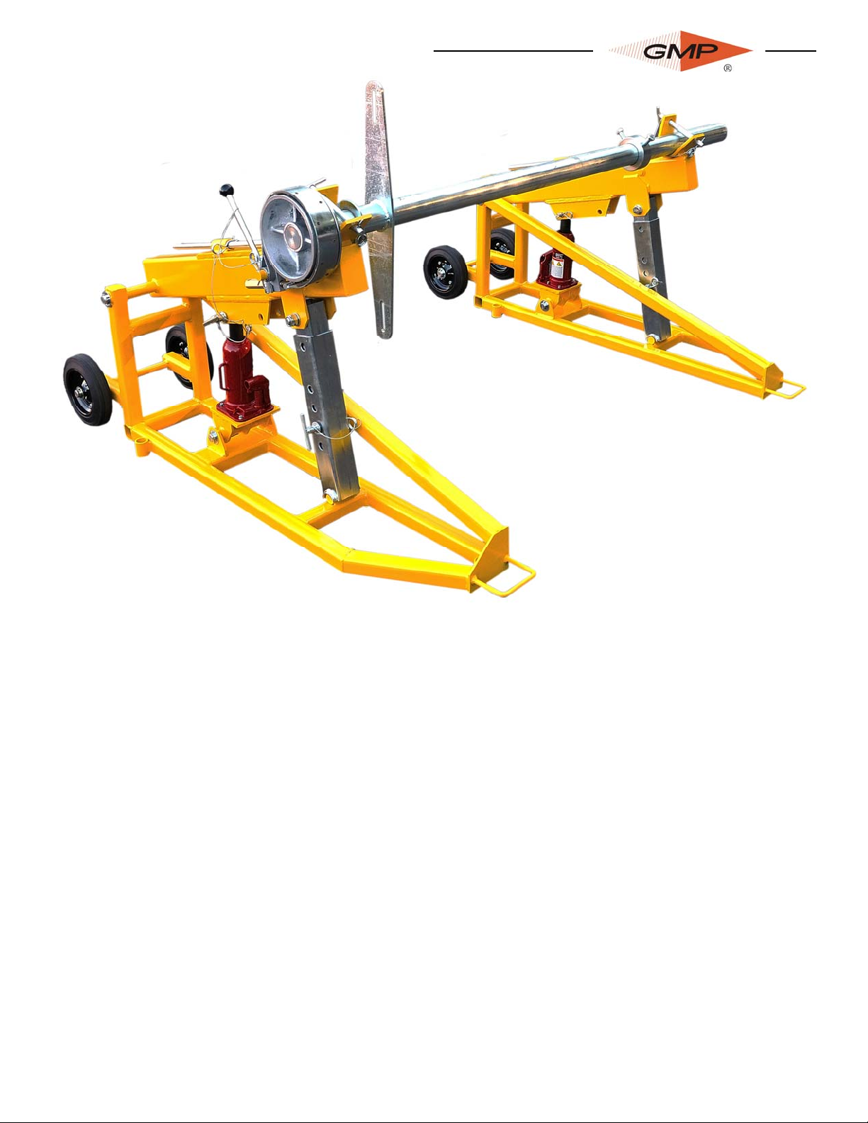
BRAKED DRUM
STAND
For Drums up to 8800 lbs.
Operation and Maintenance
Model 74540
All rights reserved. No part of this publication may be copied, reproduced or transmitted in any form whatsoever without
the written permission of General Machine Products Co., Inc.
General Machine Products Co., Inc. • 3111 Old Lincoln Hwy • Trevose, PA 19053 • USA
TEL: +1-215-357-5500 • FAX: +1-215-357-6216 • EMAIL: info@gmptools.com WEB: www.gmptools.com
8/4/2011 Ver 1 USA AK
32800

Rev.no Date Details Author
01 08-2011 Reformat for US A. Konschak
2

CONTENTS
1. Introduction and Safety Instructions
2. General Description and Specification
3. Operating Procedures
4. Maintenance
3

1.0 INTRODUCTION
Founded by engineer George M. Pfundt in 1936, GMP started operations in a downtown Philadelphia building as a specialty machine
shop doing work for the local Bell Telephone company and for the
electric utility company. GMP expanded to a production shop after
landing a contract with Western
Electric Company and, subsequently, forming a close relationship with Bell Telephone Labora-
tories in Murray Hill, N.J., which
enabled it to manufacture prototypes of products for experimental use within the Bell System.
Having outgrown the original factory building, the company built
a 100,000 square foot plant in Trevose, PA (a Philadelphia suburb) and moved there in 1957. Today GMP is recognized as a
premier worldwide supplier of specialty tools and equipment for
the outside plant marketplace. The company's products are known for their robust design and durability to withstand many years of frequent use.
4

SAFETY INSTRUCTIONS
THIS EQUIPMENT MUST ONLY BE USED BY AUTHORIZED PERSONNEL, WHO
HAVE BEEN SUITABLY TRAINED AND COMPETENT TO DO SO.
THESE INSTRUCTIONS ARE TO BE MADE AVAILABLE TO
OPERATORS OF THIS EQUIPMENT AT ALL TIMES, FAILURE TO
OBSERVE THESE SAFETY INSTRUCTIONS COULD RESULT IN
SERIOUS PERSONAL INJURY AND / OR PROPERTY DAMAGE.
1. Read and understand the operation and maintenance manual supplied with this
equipment. Keep it in a convenient place for future reference.
2. Keep children and untrained personnel away from this equipment while in operation.
3. Keep all guards and safety devices in place. Do not operate this equipment with
guards removed or damaged.
4. Keep hands, feet and loose clothing away from moving parts.
5. Always stop the machine to carry out lubrication or servicing.
6. Check machine before starting for worn or damaged parts. Check that all nuts and
bolts are tight.
7. If machine is left unattended, ensure that unauthorized use is prevented.
8. Never leave the machine unattended while in use.
9. Consider the use of safety barriers, especially when used in public places.
10. Beware of pinch points involved with rotating components, e.g. rope/cable drums,
capstans, bullwheels, shafts and chain drives.
11. Beware of hot surfaces, especially around the engine, engine exhaust pipe and hydraulic oil tank.
12.Some component and assembly parts are in excess of 55lb (25kg) . When lifting
care must be taken, ensure sufficient man power/lifting gear is available, to prevent personal injury and damage to the machine.
13.Beware of exposed electrical contacts especially around the engine. Do not
touch, or allow metal objects to come into contact.
14. Waste engine and hydraulic oils are to be disposed of via an environmentally acceptable method – e.g. passed on for recycling.
15. Wear ear protection when engine is running to prevent ear damage.
16. Machine may cause additional fire hazard if involved in an existing fire due to gasoline, diesel, oil and hydraulic oils involved.
17. No personnel are to be in manholes or ducts when the winch is being operated.
18. The machine must be operated on firm ground.
19. Stay clear of cables or lines under tension.
20. Only use the machine for its intended purpose.
21. Do not tamper with pressure relief valves or pressure reducing valves.
22. Rear stabilizing props must be down and on solid surface before use.
5

2.0 GENERAL DESCRIPTION & SPECIFICATON
The Braked Drum Stand is compact in size. Each side frame is fitted with wheels to allow for easy transportation. Drum lifting is achieved with two hand operated hydraulic jacks. An adjustable band brake provides controlled cable tensioning.
Maximum drum weight: 8820 lbs. (4000kg)
Maximum drum width: 64.6 in. (1640mm)
Maximum drum diameter: 70.9 in. (1800mm)
Minimum drum diameter: 59.1 in. (1500mm)
6

3.0 OPERATING PROCEDURE
IT IS IMPERATIVE THAT ALL PERSONS USING, OPERATING OR MAINTAINING THIS EQUIPMENT BE FULLY
TRAINED AND COMPETENT TO DO SO, AND HAVE READ THE ENTIRE OPERATING MANUAL. GENERAL MACHINE PRODUCTS CO., INC. CANNOT BE HELD RESPONSIBLE FOR MIS-USE OF THIS EQUIPMENT.
Brake Activation Lever
Brake Band Assembly
Jack Pivot Pin
4.1 The drum stand components should be placed in line, on firm level ground with appropriate spacing to
4.2 Slide the drum shaft assembly through the drum and attach the drum locking collar to the opposite side.
4.3 Four jack lifting positions are provided on the props, each to suit a range of drum diameters.
4.4 With the lifting arms in the lowered position, remove the brake band assembly and the shaft retaining
4.5 Continue operating the jacks until the drum is raised clear of the ground, and the hole in the support prop
4.6 Secure brake driving arm to the reel with appropriate sized lag bolt and washers.
4.7 Fit the brake band assembly to the brake drum with the operating handle uppermost, and secure with
4.8 Adjust the Brake tensioner as required.
4.9 To withdraw the drum, this procedure may be reversed. Care should be taken to ensure that the drum
Brake Tensioner
Jack
accommodate the reel. Anchor in position.
Tighten the locking collar screws.
Assemble the jack pivot pin into the selected hole and fully engage in correct position. Ensure that the
same hole is used for both lifting arms.
Refer to diagram on the jack body for information on use. Ensure that the prop support retaining pins
are always removed before using the lifting jack.
pins. Roll the drum into the drum stand, ensuring that the cable or rope will be pulled from the top of the
drum, and that the brake drum is on the correct side. Simultaneously raise each lifting arm using the
jacks until the shaft is seated in the lifting arm pockets. Replace retaining pins.
lines up with the hole in the lifting arm. Reinsert prop support retaining pins. Pressure may now be released from the jack, thus allowing the support props to take the full weight of the drum.
the retaining clip.
weight is taken by the hydraulic jacks before removing the prop support prop retaining pin.
Prop Support & Pin
Lag Bolts & Washers
Brake Driving Arm
7

4.0 MAINTENANCE
This equipment has been designed to provide a long and useful life providing certain precautionary measures are taken.
Before putting into service the first time, check that all parts are present and assembled correctly.
Before using, check that the brake drum and brake band is clean and free from oil, dirt or other contami-
nants. Check that the hydraulic jacks operate smoothly. Check the condition of all retaining pins and ‘R’
clips, replace if damaged.
When finished using, wipe the paint-work down with an oiled cloth. Lightly grease the pivot points with
general-purpose medium grease. Ensure that the hydraulic jacks are lowered as far as possible and apply
a thin layer of grease around the joint between piston and body. Store in clean dry conditions.
If this equipment is left outside for any extended period of time, protect against atmospheric corrosion by
applying grease to unprotected surfaces. This applies in particular to the hydraulic jack piston if it is left
extended.
8

9

GMP • 3111 Old Lincoln Hwy • Trevose, PA 19053 • USA
TEL: +1-215-357-5500 • FAX: +1-215-357-6216 • EMAIL: info@gmptools.com
10
 Loading...