

Strand Tensionmeter
Operation and
GMP
Maintenance Manual
1

2

Table of
General 3
contents
General
Precautions 5
Calibration Chart 6
Temperature Compensation Charts 8
Dial 16
Using the Tensionmeter 16
Accessory Saddle 18
Re-calibration 19
An intensive study by the National Electric Safety
Code Clearances Subcommittee has resulted in a
completely new "Uniform System of Clearances"
adopted in the 1990 and subsequent editions of the
NESC. This revision places renewed emphasis on
utilities' practices for engineering and stringing of
aerial cables to maintain proper cable clearances
under the various specified conditions. The ability
to accurately measure strand tensions in the field is
essential for compliance with the code.
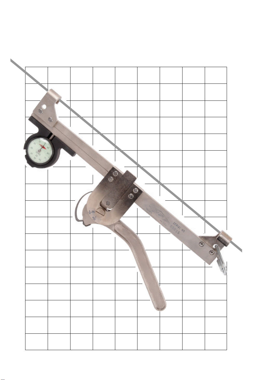
The GMP Strand Tensionmeter, also called a B
Strand Dynamometer, is a precision instrument designed to measure the tension of certain specific
zinc-coated guy wires and messenger cables per
ASTM A-475. The specific sizes and type(s) of
cable(s) with which this unit is compatible are
listed in the calibration chart which has been prepared for this specific serial numbered tensionmeter and which bears that identical serial number.
3

The following list shows the various sizes, types
and designations of messenger cables for which
the tools can be calibrated:
Nominal Diameter
Inches mm Designation Description
1/4 6.35 6.6M 1 X 7 EHS
5/16 7.94 6M 1 X 7 Utility Grade
5/16 7.94 10M 1 X 7 EHS
3/8 9.52 10M 1 X 7 Utility Grade
7/16 11.11 16M 1 X 7 EHS
7/16 11.11 16M 1 X 7 Utility Grade
To obtain an accurate measurement it is imperative
that the strand to be measured be positively identified as to its actual diameter and its grade, either
Utilities Grade or Extra-High Strength. Secondly,
the Strand Tensionmeter to be used must have a
current calibration chart with a corresponding serial number which has a calibration for the specific
strand you have identified.
The Tensionmeter measures the force required to
deflect the strand to an out-of-line position and
registers the amount of force required on the integral dial. The actual strand tension is then determined by referring to the calibration chart specifically prepared for and furnished with each Tensionmeter, which converts the dial indicator reading into the actual tension value.
The instrument measures tension in pounds force
to within an accuracy of three percent (± 3%) or ±
150 pounds, whichever is greater.
4

The Tensionmeter is primarily made from nickelplated steel and is furnished in a hard shell plastic
carrying case; the interior is cushioned with foam
for unit protection.
Each Tensionmeter has a registered serial number
stamped on the unit.
pPrecautions
• Do not measure tensions of 1/2" diameter
strand with the cable in place; these tension
values usually exceed 10,000 pounds.
• Do not drop or jar the Tensionmeter.
• Raise and lower the instrument with a hand
line.
• Keep the device away from dirt, grease, sand
or water.
• Keep foreign material from damaging the dial
or plunger.
• Maintain the unit in the carrying case when-
ever possible.
• Make certain that the correct calibration chart
is always kept in the carrying case.
• Use the Tensionmeter only on strand type and
sizes shown on the calibration chart.
• Do not use this device on strand tensioning
applications exceeding 10,000 pounds.
5

Calibration
Chart
Included with each Tensionmeter is a calibration
chart registered under the same serial number as
the Tensionmeter. This chart is to be used for interpreting the readings for that specific instrument
only.
No other chart should be used. No other type of
strand should be used.
The table across the top of the chart lists the commonly used strand sizes for which the Tensionmeter was calibrated, as well as the handle position
for each type of strand. The data in the chart indicates the dial reading of the Tensionmeter corresponding to the amount of strand tension in 100
pound increments for the normal tension range of
each strand size.
The chart indicates the date when the initial calibration was made. If the chart is lost, the Tensionmeter must be returned for re-calibration.
Temperature
Compensation
Charts
Strand tension is affected by ambient temperature.
Generally speaking, strand tension increases as
temperature decreases due to the strand contraction
and, conversely, strand tension decreases as temperature rises, due to expansion. The Strand Tensionmeter will measure the actual tension at the
ambient temperature at the time of the measurement. You should consult with the Outside Plant
Facilities Engineer as to the proper strand tension
for the ambient temperature at the time of measurement.
6

Temperature
Compensation
Charts
(continued)
Line charts are provided in these instructions in order for the user to determine how to compensate for
changes in ambient temperature. The charts are derived from the recommended values expressed in
the referenced industry standard practices. They are
not intended to supersede any tension calculations
which might be provided to the user by the utility's
plant engineering department.
For example, assume that the engineering specifications for tensioning a certain 300 ft. span of 1/4"
Extra-High Strength strand (i.e. Bell System 6.6M)
calls for the strand to be at 600 lbs. at 60 degrees F.
When you are at the work site, your thermometer
indicates an ambient temperature of 86 degrees. Referring to the Temperature Compensation Chart for
that specific strand, you will see three lines. Find
the one which corresponds to spans 250-450 feet.
Notice that 600 pounds on the vertical axis corresponds to 60 degrees on the horizontal axis. Now
continue right along the horizontal axis to 86 degrees. With a straight edge, follow from that point
vertically until you intersect with the 250-450 ft.
line. 86 degrees corresponds to just over 500
pounds. That is the strand tension compensated for
86 degrees ambient. On the Tensionmeter Calibration Chart for 1/4" EHS, locate 500 Ibs. and convert
to the dial indicator reading. That is the dial indicator number to shoot for when tensioning this particular strand.
An analog thermometer is provided in each Strand
Tensionmeter storage case for the purpose of accurately determining the ambient temperature at the
time of the measurement. Be sure to hold the thermometer by the dial and not by the sensing stem
and to allow at least two minutes for the thermometer to stabilize itself.
7

1000
900
800
700
1/4” Extra High Strength
Temperature Compensation Chart
Per BSP 627-210-018 iss. 1
Tension Pounds Force
600
500
400
0 20 40 60 80 100
Temperature F
SPANS < 250' SPANS 250-450' SPANS >450'
8

1400
1350
1300
1250
1200
1150
1/4” Extra High Strength
Temperature Compensation Chart
Per GTEP 627-100-200 iss.2
1100
Tension Pounds Force
1050
1000
950
900
0 20 40 60 80 100
Temperature F
SPANS < 250' SPANS 250-450' SPANS >450'
9

2500
Tension Pounds Force
2400
2300
2200
2100
5/16” Extra High Strength
Temperature Compensation Chart
Per GTEP 627-100-200 iss.2
2000
1900
1800
1700
0 20 40 60 80 100
Temperature F
SPANS <400 SPANS >400
10

4400
Tension Pounds Force
4300
4200
4100
4000
3900
7/16” Extra-High Strength
Temperature Compensation Chart
Per GTEP 627-100-200 iss.2
3800
3700
3600
3500
3400
0 20 40 60 80 100
Temperature F
ALL SPANS
11

1600
1500
1400
1300
1200
5/16” Utilities Grade
Temperature Compensation Chart
Per BSP 627-210-018 iss. 1
Tension Pounds Force
1100
1000
900
800
0 20 40 60 80 100
Temperature F
SPANS < 250' SPANS 250-450' SPANS >450'
12

2700
2600
2500
2400
2300
2200
3/8” Utilities Grade
Temperature Compensation Chart
Per BSP 627-210-018 iss. 1
2100
Tension Pounds Force
2000
1900
1800
1700
0 20 40 60 80 100
SPANS <400 SPANS >400
Temperature F
13

4400
4200
4000
3800
7/16” Utilities Grade
Temperature Compensation Chart
Per BSP 627-210-018 iss. 1
3600
3400
3200
3000
0 20 40 60 80 100
Temperature F
ALL SPANS
14

9200
9000
8800
8600
8400
8200
1/2” Utilities Grade
Temperature Compensation Chart
Per BSP 627-210-018 iss. 1
8000
7800
7600
7400
7200
0 20 40 60 80 100
Temperature F
ALL SPANS
15

Dial
The calibrated dial reads 0 to 100. The majority of
recorded measurements will be within this range
and are readjust as the graduation appears on the
dial.
However, on high load measurements, it is possible for the needle to make one complete revolution
past zero. For these readings, it is necessary to add
100 to the graduation indicated by the needle.
Using the
Tensionmeter
Accurate strand tension measurement requires that
a section of strand be at least twenty feet long and
free from damage or corrosion. If cable is in place,
remove one ring or cable support or un-lash sufficiently to obtain about two feet of unobstructed
strand.
Suspend the instrument on the strand by the hooks
located at each end of the tension bar with the handle projecting downward.
With the unit in position, always check to make
certain that the dial indicator reads zero. If the dial
indicator does not read zero, loosen the slotted
screw located in the dial shroud. Rotate the dial
slightly until the dial indicator reads zero and retighten the screw. As an alternate to "re-zeroing"
the unit each time the installed position of the Tensionmeter is changed, place the unit in the position
in which it is to be used and note the number of
graduations above or below the zero mark. Once
the Tensionmeter is installed and set, add or subtract those graduations to/from the dial reading before referring to the chart.
16

Using the
Tensionmeter
(continued)
Locate the column on the calibration chart for the
grade and diameter of strand to be tested and note
the correct handle position. (An asterisk alongside
of the handle position number means that the accessory saddle must be used.* See the next section
titled Accessory Saddle before proceeding.) Pull
the handle down until the bottom edge of the cam
plunger moves upward and stops at the correct position numbered on the cam case. The strand will
be deflected between the suspension hooks when
the handle engages into the detent at the correct
numbered position. Read and record the dial indicator number.
IMPORTANT: The calibrated dial reads 0 to
100. The majority of recorded measurements
will be within this range and are read exactly as
the number appears on the dial. On high load
measurements, however, it is possible for the
needle to make one complete revolution past
zero. For these readings, it is necessary to add
100 to the number indicated by the needle.
Take two additional readings moving the Tensionmeter approximately 1/4" along the strand for each
reading. Read and record each dial indicator number.
Discard the high and low readings and use only the
intermediate reading as the correct value. Refer to
the calibration chart under the specific strand diameter and locate the dial reading closest to the
observed reading. Move to the left column showing the corresponding amount of tension in pounds
force.
* on certain older design units
17

Accessory
Saddle
Certain Strand Tensionmeters manufactured and
sold between Jan. 1991 and July 1992 had cam
plungers of a different design than either the
AT&T units which preceded them or the current
GMP design which follows them. These units bear
serial numbers in the range 1700-2300 stamped on
the handle. When checking the tension on 1/4”,
5/16” or 3/8” diameter strand, a part called the accessory saddle block must be used to achieve dial
indicator movement and a correct tension reading.
This accessory saddle block is a rectangular steel
block which mounts on top of the cam plunger and
is held in place by two 7/16" head hex screws. The
calibration charts furnished with these units have
an asterisk (*) alongside the handle position numbers for the strand sizes where the accessory saddle must be used. A handle position number with
no asterisk means that the accessory saddle must
not be used. The accessory saddle applies only to
the units described above and does not apply to
AT&T units, nor does it apply to GMP units with
5 digit serial numbers.
18

Recalibration
To maintain optimum service, the Tensionmeter
should be re-calibrated periodically. With moderate to heavy use, a calibration check should be performed every year. The initial calibration date is
shown on each calibration chart. No attempt
should be made to disassemble, repair or recalibrate in the field. If a unit is not responding to
normal use, it should be placed in the carrying case
with the calibration chart and returned to General
Machine Products Co., Inc. for service. Please supply a contact name, address, phone number and a
reason for return.
Calibration
Dates
19

General Machine Products Co., Inc.
3111 Old Lincoln Highway
Trevose, PA 19053-4996 USA
TEL: 215-357-5500
FAX: 215-357-6216
E-MAIL: info@GMPtools.com
WEB: http://www.GMPtools.com
GMP reserves the right, without notice, to make changes in
equipment design or components as progress in engineering or
manufacturing methods may warrant.
All contents ©2005 GMP
20
 Loading...