

Page 1
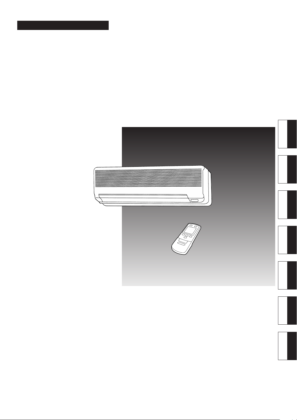
ROOM AIR CONDITIONER
OPERATING MANUAL
SPLIT TYPE
BEDIENUNGSANLEITUNG
MODE D’EMPLOI
MANUAL DE FUNCIONAMIENTO
MANUALE DI ISTRUZIONI
ΕΓΧΕΙΡΙ∆ΙΟ ΛΕΙΤΟΥΡΓΙΑΣ
MANUAL DE INSTRUÇÕES
English
Deutsch
Français
Español
Italiano
EλληvIkά
Português
KEEP THIS MANUAL
FOR FUTURE REFERENCE
P/N9373471011
Page 2

Page 3
CONTENTS
SAFETY PRECAUTIONS .......................................... 1
NAME AND FUNCTION OF PARTS ......................... 2
PREPARATION .......................................................... 4
OPERATION .............................................................. 6
AIR DIRECTION ADJUSTMENT .............................. 9
TIMER OPERATION ................................................11
SLEEP TIMER OPERATION ................................. 12
CARE AND MAINTENANCE ............................... 13
TROUBLE SHOOTING .........................................15
OPERATION DETAILS.......................................... 16
SPECIFICATIONS ................................................. 18
SAFETY PRECAUTIONS
● Before using the appliance, read these “PRECAUTIONS” thoroughly and operate in the correct way.
● The instructions in this section all relate to safety; be sure to maintain save operating conditions.
● “DANGER”, “WARNING” and “CAUTION” have the following meanings in these instructions:
DANGER!
WARNING!
CAUTION!
DANGER!
This mark indicates procedures which, if improperly performed, are most likely to
result in the death of or serious injury to the user or service personnel.
This mark indicates procedures which, if improperly performed, might lead to the
death or serious injury of the user.
This mark indicates procedures which, if improperly performed, might possibly result
in personal harm to the user, or damage to property.
● Do not attempt to install this air conditioner by yourself.
● This unit contains no user-serviceable parts. Always consult authorized service per-
sonnel for repairs.
● When moving, consult authorized service personnel for disconnection and installation of the unit.
● Do not become over-exposed to cold air by staying in the direct path of the air flow of
the air conditioner for extended periods of time.
● Do not insert fingers or objects into the outlet port or intake grilles.
● Do not start and stop air conditioner operation by turning off the electrical breaker or
disconnecting the power supply plug and so on.
● Take care not to damage the power supply cord.
● In the event of a malfunction (burning smell, etc.), immediately stop operation, turn
off the electrical breaker or disconnect the power supply plug, and consult authorized
service personnel.
CAUTION!
● Provide occasional ventilation during use.
● Do not direct air flow at fireplaces or heating apparatus.
● Do not climb on, or place objects on, the air conditioner.
● Do not hang objects from the indoor unit.
● Do not set flower vases or water containers on top of air conditioners.
● Do not expose the air conditioner directly to water.
● Do not operate the air conditioner with wet hands.
● Do not pull power supply cord.
● Turn off power source when not using the unit for extended periods.
● Always turn off the electrical breaker or disconnect the power supply plug whenever
cleaning the air conditioner or the air filter.
● Connection valves become hot during Heating; handle with care.
● Check the condition of the installation stand for damage.
● Do not place animals or plants in the direct path of the air flow.
● Do not drink the water drained from the air conditioner.
● Do not use in applications involving the storage of foods, plants or animals, precision
equipment, or art works.
● Do not apply any heavy pressure to radiator fins.
● Operate only with air filters installed.
● Do not block or cover the intake grille and outlet port.
● Ensure that any electronic equipment is at least one metre away from either the in-
door or outdoor units.
● Avoid installing the air conditioner near a fireplace or other heating apparatus.
● When installing the indoor and outdoor unit, take precautions to prevent access to
infants.
● Do not use inflammable gases near the air conditioner.
En-1
Page 4
NAME AND FUNCTION OF PARTS
Instructions relating to heating (*) are applicable only to “HEAT & COOL MODEL” (Reverse Cycle).
For details of operation, see the pages indicated by the (☞) mark.
Fig. 1
Fig. 4
E
F
9
8
0
A
1
2
4
3
Fig. 2
B
5
6
DC
7
Fig. 3
Fig. 5
H
I
Fig. 6
P
J
R
KG
S
L
V
W
X
M
N
T
U
Y
Z
QO
Fig. 7
En-2
Page 5
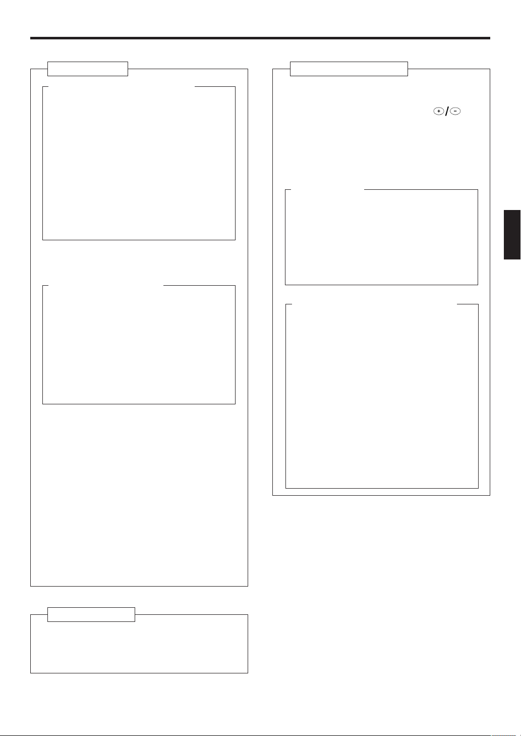
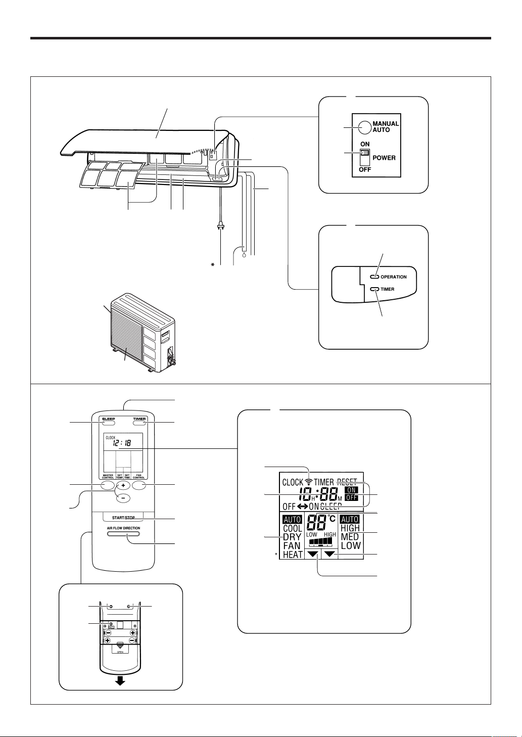
Fig. 1 Indoor Unit
1 Operating Control Panel (Fig. 2)
2 MANUAL AUTO button
This button can be used for temporary operation in the AUTOMATIC mode in the event the
remote control unit is unavailable.
Press the MANUAL AUTO button
● Fan speed will be set to “AUTO” and the
thermostat will be set for “normal”.
● To stop operation, either press the
MANUAL AUTO button once again, or set
the POWER switch to OFF.
3 POWER switch
ON :Set to this position when using the unit.
OFF : Set to this position when not using the
unit for an extended period of time.
4 Remote Control Signal Receiver (☞ P. 5)
Signals from the remote control unit are received here.
5 Indicator Lamps (Fig. 3)
These indicator lamps show the current operating status.
6 OPERATION Indicator (red)
● Lights when unit is operating.
● Flashes quickly for about one second when
a signal is received from the remote control unit.
*● Flashes slowly during defrosting opera-
tion. (☞ P. 17)
7 TIMER Indicator (green)
Lights during TIMER operation.
8 Air Intake Grille
Air is taken in here.
9 Air Filter (☞ P. 14)
Removes all dirt and dust from the air.
0 Air flow-direction Louvers (☞ P. 9)
Control airflow in the vertical (up-down) direction.
A Right-left Louvers (☞ P. 10)
(behind Air flow-direction Louvers)
Control airflow in the horizontal (right-left) direction.
B Pipe Unit
* C Power Plug
D Drain Hose
Moisture condensed from the air during Cooling and Drying operations is drained here.
Fig. 5 Remote Control Unit
G SLEEP Button (☞ P. 12)
H MASTER CONTROL Button
I SET TEMP./SET TIME Buttons (
J Signal Transmitter
K TIMER Button (☞ P. 11 and 12)
L FAN CONTROL Button
M START/STOP Button
N AIR FLOW DIRECTION Button (☞ P. 9)
Rear side (Fig. 6)
O TIME ADJUST Button (☞ P. 5)
P ACL Button (☞ P. 4)
(located inside battery compartment)
This button is used when replacing batteries.
Q TEST RUN Button
This button is used when testing the air conditioner after installation. Do not use under
normal conditions.
R Remote Control Unit Display (Fig. 7)
S Transmit Indicator
T Clock Display
● When CLOCK is displayed, the current time
is shown in 24-hour format (0:00 to 23:59).
● When TIMER is displayed, the timer setting is shown in 24-hour format (0:00 to
23:59).
● When SLEEP timer has been selected, the
display shows the remaining time until the
unit turns off (0H:05M to 9H:55M).
U Operating Mode Display
V Timer Mode Display
W Fan Speed Display
X Temperature Set Display
Y Timer Set Indicator
Z Temperature Set Indicator
)
Fig. 4 Outdoor Unit
E Air inlet
(Rear and side panels)
F Air outlet
Warm or cool air is blown out.
En-3
Page 6
PREPARATION
Turn on the Power
Connect the power plug to an electrical point.
1
Open the Intake Grille.
2
Set the POWER switch to ON (Fig. 2 3).
3
Close the Intake Grille.
4
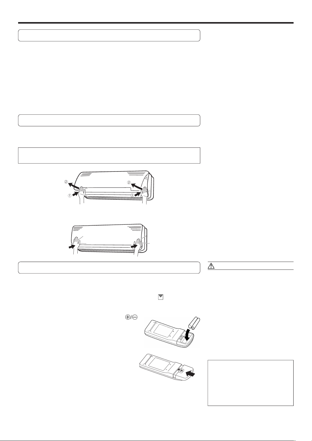
Opening/closing the Intake Grille
1 Press both lower sides of the intake grille until you hear a clicking sound.
2 Release your hands and the intake grille will open toward the front.
Do not operate the unit with the intake grille open, since malfunctions may
result.
Press the both lower sides of the intake grille until you hear a clicking sound and the
grille locks into place.
Load Batteries (R03/LR03
××
× 2)
××
Press and slide the battery compartment lid on the re-
1
verse side to open it.
Slide in the direction of the arrow while pressing the mark.
Insert batteries.
2
Be sure to align the battery polarities ( ) correctly.
Close the battery compartment lid.
3
CAUTION!
● Take care to prevent infants from
accidentally swallowing batteries.
● When not using the remote control unit
for an extended period, remove the
batteries to avoid possible leakage and
damage to the unit.
● If leaking battery fluid comes in contact
with your skin, eyes, or mouth, immediately wash with copious amounts of
water, and consult your physician.
● Dead batteries should be removed
quickly and disposed of properly, either
by placing in a public battery collection
receptacle, or by returning to appropriate authority.
● Do not attempt to recharge dry batteries.
Never mix new and used batteries, or
batteries of different types.
Batteries should last about one year
under normal use. If the remote control
unit’s operating range becomes appreciably reduced, replace the batteries and
press the ACL button with the tip of a
ballpoint pen or other small object.
En-4
Page 7

Set the Current time
Press the TIME ADJUST button (Fig. 6 O).
1
Use the tip of a ball-point pen or other small object to press the button.
Use the ( ) SET TIME buttons (Fig. 5 I) to adjust
2
the clock to the current time.
button: Press to advance the time.
button: Press to reverse the time.
(Each time the buttons are pressed, the time will be advanced/reversed in
one-minute increments; hold the buttons depressed to change the time
quickly in ten-minute increments.)
Press the TIME ADJUST button again.
3
This completes the time setting and starts the clock.
To Use the Remote Control Unit
● The remote control unit must be pointed at signal receiver (Fig. 1 4) to operate
correctly.
● Operating range: About 7 meters.
● When a signal is properly received by the air conditioner, a beeping sound will
be heard.
● If no beep is heard, press the remote control unit button again.
Remote Control Unit Holder
Insert
Press in
Screws
1 Mount the Holder. 2 Set the Remote Control Unit.
● Signals will not be transmitted properly if a wall, curtain, or other object is between the air conditioner and
the remote control unit.
● The air conditioner may fail to operate properly if
strong direct light is allowed to strike the signal receiver. Use a curtain to shade strong sunlight from
windows, and place strong lamps at a distance away
from the signal receiver.
● If another electric appliance is operated by the remote
control unit move the appliance away or consult with
authorized service personnel.
Slide up
Pull out
3 To remove the Remote
Control Unit (when use at
hand).
● Do not place the remote control unit in locations where
it may be subjected to heat from direct sunlight or
from heating apparatus.
● Do not subject the remote control unit to strong impacts, and do not allow water or other liquids to splash
on it.
● When the remote control unit is used in rooms furnished with instant-lighting type fluorescent lamps,
the air conditioner may fail to receive control signals
correctly. Consult with authorized service personnel
when purchasing a new fluorescent lamp.
En-5
Page 8

OPERATION
Instructions relating to heating (*) are applicable only to “HEAT & COOL MODEL” (Reverse Cycle).
To Select AUTOMATIC Operation
Press the START/STOP button (Fig. 5 M).
1
The air conditioner will start operation.
Press the MASTER CONTROL button to select AUTO
2
(Fig. 5 H).
The operating mode “AUTO” will appear alone in the display. The transmit indicator will flash to indicate the command has been sent, and about
three seconds later the entire display panel will reappear.
About Automatic Operation [COOLING MODEL]
● Depending on the room temperature at the time operation begins, the operating mode will be switched automatically as shown in the accompanying table. Also, depending on the operating mode, the room temperature
setting will cause the “normal” temperature to be set as
shown.
● Once the operating mode has been set, the mode will not
change even if the room temperature changes.
● In the dry mode, the fan will operate slowly to prevent
room humidity from rising, and the room fan may stop.
Room Temperature
30 °C or more Cooling 27 °C
27 °C to 30 °C Cooling 26 °C
25 °C to 27 °C Dry 24 °C
23 °C to 25 °C Dry 22 °C
Less than 23 °C Dry 20 °C
Operating
Mode
Temperature
Setting
(“normal” setting)
About AUTO CHANGEOVER Operation [REVERSE CYCLE MODEL]
● When AUTO CHANGEOVER operation is selected, the air
conditioner selects the appropriate operation mode (Cooling or Heating) in response to your room’s temperature.
● When AUTO CHANGEOVER operation first selected, the
fan will operate at very low speed for about one minute,
during which time the unit detects the room conditions
and selects the proper operating mode.
● When the air conditioner has adjusted your room’s temperature to near the thermostat setting, it will begin monitor operation. In the monitor operation mode, the fan will
operate at low speed. If the room temperature subsequently changes, the air conditioner will once again select the appropriate operation (Heating, Cooling) to adjust the temperature to the value set in the thermostat.
(The monitor operation range is ±2 °C relative to the thermostat setting.)
● If the mode automatically selected by the unit is not what
you wish, see pages 7 to 8 and select one of the mode
operation (HEAT, COOL, DRY, FAN).
To Set the Thermostat
Press the TEMPERATURE set button.
● COOLING MODEL
When set to When set to When set to When set to When set to
2K (2 °C) lower 1K (1 °C) lower “normal” 1K (1 °C) higher 2K (2 °C) higher
● REVERSE CYCLE MODEL
The temperature can be set to 27°, 25°, 23°, 21° or 19° (C).
About three seconds later, the entire display will reappear.
[COOLING MODEL]
En-6
[REVERSE CYCLE MODEL]
Example: When set to “normal”
The thermostat setting should be considered a standard value, and may differ somewhat from the actual room temperature.
Page 9

To Change the Fan Speed
Press the FAN CONTROL button (Fig. 5 L).
Each time the button is pressed, the fan speed changes in the following order:
ss s s
AUTO HIGH MED LOW
About three seconds later, the entire display will reappear.
When the FAN CONTROL is set to AUTO:
COOL : Operation begins and as the room temperature approaches that of the
thermostat setting, the fan speed switches to the low setting.
* HEAT : The fan operates at low speed at the beginning of operation or otherwise
when the temperature of the emitted air is relatively low; the fan speed
increases as the temperature of the emitted air rises.
As the difference between the thermostat setting and actual room temperature is
reduced, the fan speed becomes slower.
To Stop Operation
Press the START/STOP button.
The OPERATION indicator lamp (red) (Fig. 3 6) will light.
To Select Mode Operation
Press the START/STOP button (Fig. 5 M).
1
The indoor unit’s OPERATION indicator lamp (red) (Fig. 3 6) will light.
The air conditioner will start operating.
Example: When set to AUTO
Press the MASTER CONTROL button (Fig. 5 H) to se-
2
lect the desired mode.
Each time the button is pressed, the mode will change in the following
order:
s
AUTO COOL DRY
About three seconds later, the entire display will reappear.
*HEAT FAN
About Mode Operation
Cooling
● Use to cool your room.
Drying
● Use for gently cooling while dehumidifying your room.
● You cannot heat the room during Drying mode.
● During Drying mode, the unit will operate at low speed;
in order to adjust room humidity, the indoor unit’s fan
may stop from time to time. Also, the fan may operate at
very low speed when detecting room humidity.
● The fan speed cannot be changed manually when Drying
mode has been selected.
Fan [COOLING MODEL]
● When using a space heater to heat the room, using the
air conditioner’s Fan setting will help prevent warm air
from collecting near the ceiling, and thus assist in distributing warm air evenly throughout the room.
● Fan operation will begin automatically when the room
temperature rises above the set temperature, and stop
when the temperature falls below the set temperature.
● If the air emitted from the unit feels too cold, increase the
temperature setting.
s
t
s
t
Example: When set to COOL
Fan [HEAT & COOL MODEL (Reverse Cycle)]
● Use to circulate air through your room without changing
its temperature.
*Heating
● Use to warm your room.
● When Heating mode is selected, the air conditioner will
operate at very low fan speed for about 3 to 5 minutes,
after which it will switch to the selected fan setting. This
period of time is provided to allow the indoor unit to warm
up before begin full operation.
● When the room temperature is very low, frost may form
on the outside unit, and its performance may be reduced.
In order to remove such frost, the unit will automatically
enter the defrost cycle from time to time. During defrost
cycle, the red OPERATION indicator will flash, and the
heat operation will be interrupted.
En-7
Page 10

OPERATION
To Set the Thermostat
Press the TEMPERATURE set button (Fig. 5 I).
button: Press to increase the thermostat setting.
button: Press to lower the thermostat setting.
●Thermostat setting range:
COOLING MODEL
HEAT & COOL Heating ............................. 16 to 30 °C
MODEL Cooling/Drying .................18 to 30 °C
About three seconds later, the entire display will reappear.
NOTE:
● The thermostat setting should be considered a standard value, and may differ
somewhat from the actual room temperature.
● During Fan mode, set the unit to “– –” for continuous fan operation regardless of
room temperature. [COOLING MODEL ONLY]
● The thermostat cannot be used to set room temperature during the FAN mode
(the temperature will not appear on the remote control unit’s display).
[HEAT & COOL MODEL (Reverse Cycle) ONLY]
Cooling/Drying .................18 to 30 °C
Fan .................................... 17 to 30 °C
To Set the Fan Speed
Press the FAN CONTROL button (Fig. 5 L).
Each time the button is pressed, the fan speed changes in the following order:
AUTO HIGH MED LOW
About three seconds later, the entire display will reappear.
When set to AUTO:
Cooling : Operation begins and as the room temperature approaches that of
the thermostat setting, the fan speed switches to the low setting.
Fan: [COOLING MODEL]
Fan speed is selected automatically in accordance with nearby room
temperature.
Fan: [HEAT & COOL MODEL (Reverse Cycle)]
Fan operation will alternate between low speed and off.
* Heating : The fan operates at low speed at the beginning of operation or other-
wise when the temperature of the emitted air is relatively low; the fan
speed increases as the temperature of the emitted air rises.
However, the fan will operate at very low speed when the air issued
from the indoor unit is low (☞ P. 7).
s
sss
To Stop Operation
Press the START/STOP button.
Example: When set to 26 °C
Example: When set to AUTO
* During Heating mode:
Set the thermostat to a temperature setting that is higher than the current room
temperature. The Heating mode will not
operate if the thermostat is set lower than
the actual room temperature.
During Cooling/Dry mode:
Set the thermostat to a temperature setting that is lower than the current room
temperature. The Cooling and Dry modes
will not operate if the thermostat is set
higher than the actual room temperature
(in Cooling mode, the fan alone will operate).
During Fan mode:
You can not use the unit to heat and cool
your room.
En-8
Page 11

AIR DIRECTION ADJUSTMENT
Instructions relating to heating (*) are applicable only to “HEAT & COOL MODEL” (Reverse Cycle).
● Use the remote control unit’s AIR FLOW DIRECTION button to adjust the up-down direction of airflow. (Left-right air direction is changed by manually moving the air louvers.)
● Begin unit operation and confirm that the airflow-direction louvers are stopped before setting the airflow-direction.
WARNING!
● Do not put fingers or other objects into the air louvers; an internal fan operates at high speed and
could result in personal injury or damage.
● Do not operate the air conditioner with the airflow louvers blocked, since malfunction could
result.
Automatic Airflow-Direction Adjustment
● The airflow-direction louvers is set automatically in accordance with the operating mode (cooling, etc.).
During Cooling, Dry,
and Fan modes
Horizontal direction
● During automatic operation mode (☞ P. 6), the airflow-direction louvers will switch
automatically in the following way:
Cooling: For four minutes after operation begins, the louver’s direction is at a
slight downward diagonal; thereafter, the direction switches to horizontal.
Slight downward
diagonal
After four minutes
Dry, Monitor mode: Horizontal direction.
*Heating: At the beginning of operation the louvers will direct the airflow down-
ward to the floor area; as the room is gradually warmed, the flaps will
change to permit double direction heating.
Downward
Room heats up
*During Heating mode
Double direction
Horizontal
Double direction
● Always use the remote control unit’s
airflow-direction button to change the
position of the up-down airflow-direction louvers. Do not attempt to set the
louvers by hand, since it may result in
improper operation. In this case, stop
the air conditioner temporarily and
then restart to return the louvers to
proper operation.
● Never operate the air conditioner when
the up-down airflow-direction louvers
are closed.
● When the operating mode is changed,
the up-down airflow-direction louvers
will automatically change to their
standard direction.
● In the cooling and drying modes, dew
may condense around and drop from
the air outlet ports when the louvers
are set to the other cooling range. As
a result, we recommend that this position be used only for brief periods.
● A certain time interval may be required
after pressing the remote control unit’s
airflow-direction button until the
louvers are set to the desired position.
During that interval, the airflow-direction button will not respond, even if
pressed.
● When the air conditioner operation is
stopped, the up-down airflow direction
louvers automatically move to close
the outlet vent.
● If you wish to select a different airflow direction, you may use the remote control
unit’s airflow-direction button to choose a different setting.
En-9
Page 12

AIR DIRECTION ADJUSTMENT
Adjusting the Airflow-Direction
Press the AIR FLOW DIRECTION button.
● This control allows you to select a desired airflow direction.
Types of airflow:
Horizontal
Slight downward
diagonal
Downward
Downward
diagonal
In order to heighten the efficiency of cooling and drying modes, the airflow-direction louvers should be set within the following ranges:
For Cooling: Horizontal, slight downward diagonal.
*For Heating: Double direction, downward diagonal, downward.
Double direction
Adjusting the Right-Left Direction
Adjust with the right-left louvers.
● Manually adjust the right-left louvers to the desired direction.
Right-left louvers
(The louver on the very left in not movable)
En-10
Hold the tip of the
louver and move
gently to right or left.
Page 13

TIMER OPERATION
Before using the timer function, be sure that the remote control unit is set to the correct current time (☞ P. 5).
To Use the ON timer or OFF timer
Press the START/STOP button (Fig. 5 M)
1
(if the unit is already operating, proceed to step 2).
The indoor unit’s OPERATION indicator lamp (red) (Fig. 3 6) will light.
Press the TIMER button (Fig. 5 K) to select the OFF
2
timer or ON timer operation.
Each time the button is pressed the timer function changes in the following order:
RESET OFF ON
PROGRAM(OFF → ON, OFF ← ON)
The indoor unit’s TIMER indicator lamp (green) (Fig. 3 7) will light.
sss
t
Use the SET TIME buttons (Fig. 5 I) to adjust the de-
3
sired OFF time or ON time.
Set the time while the time display is flashing (the flashing will continue
for about five seconds).
button: Press to advance the time.
button: Press to reverse the time.
About three seconds later, the entire display will reappear.
To Cancel the Timer
Use the TIMER button to select “TIMER
RESET”.
The air conditioner will return to normal
operation.
To Change the Timer Settings
Perform steps 2 and 3.
To Stop Air Conditioner Operation
while the Timer is Operating
Press the START/STOP button.
To Change Operating Conditions
If you wish to change operating conditions
(Mode, Fan Speed, Thermostat Setting, Air
flow direction), after making the timer
setting wait until the entire display
reappears, then press the appropriate
buttons to change the operating condition
desired.
To Use the PROGRAM timer
Press the START/STOP button (Fig. 5 M)
1
(if the unit is already operating, proceed to step 2).
The indoor unit’s OPERATION indicator lamp (red) (Fig. 3 6) will light.
Set the desired times for OFF timer and ON timer.
2
See the section “To Use the ON timer or OFF timer” to set the desired
mode and times.
About three seconds later, the entire display will reappear.
The indoor unit’s TIMER indicator lamp (green) (Fig. 3 7) will light.
Press the TIMER button (Fig. 5 K) to select the PRO-
3
GRAM timer operation (either OFF → ON or OFF ← ON
will display).
The display will alternately show “OFF timer” and “ON timer”, then change
to show the time setting for the operation to occur first.
● The PROGRAM timer will begin operation. (If the ON timer has been
selected to operate first, the unit will stop operating at this point.)
About three seconds later, the entire display will reappear.
About the PROGRAM timer
● The PROGRAM timer allows you to integrate OFF timer and ON timer operations
in a single sequence. The sequence can involve one transition from OFF timer to
ON timer, or from ON timer to OFF timer, within a twenty-four hour period.
● The first timer function to operate will be the one set nearest to the current time.
The order of operation is indicated by the arrow in the remote control unit’s display (OFF → ON, or OFF ← ON).
● One example of PROGRAM timer use might be to have the air conditioner automatically stop (OFF timer) after you go to sleep, then start (ON timer) automatically in the morning before you rise.
To Cancel the Timer
Use the TIMER button to select “TIMER
RESET”.
The air conditioner will return to normal
operation.
To Change the Timer Settings
1. Follow the instructions given in the section “To Use the ON Timer or OFF Timer”
to select the timer setting you wish to
change.
2. Press the TIMER button to select either
OFF → ON or OFF ← ON.
To Stop Air Conditioner Operation
while the Timer is Operating
Press the START/STOP button.
To Change Operating Conditions
If you wish to change operating conditions
(Mode, Fan Speed, Thermostat Setting, Air
flow direction), after making the timer
setting wait until the entire display
reappears, then press the appropriate
buttons to change the operating condition
desired.
En-11
Page 14

SLEEP TIMER OPERATION
Instructions relating to heating (*) are applicable only to “HEAT & COOL MODEL” (Reverse Cycle).
Unlike other timer functions, the SLEEP timer is used to set the length of time until air conditioner operation is stopped
(for example, 2:00 hours).
To Use the SLEEP timer
While the air conditioner is operating or stopped, press the
SLEEP button (Fig. 5 G).
Both the indoor unit’s OPERATION indicator lamp (red) (Fig. 3 6) and the TIMER
indicator lamp (green) (Fig. 3 7) will light.
To Change the Timer Settings
Press the SLEEP button (Fig. 5 G) once again and set the time
using the SET TIME buttons (Fig. 5 I).
Set the time while the Timer Mode Display is flashing (the flashing will continue for
about five seconds).
button: Press to advance the time.
button: Press to reverse the time.
About three seconds later, the entire display will reappear.
About the SLEEP timer
To Cancel the Timer:
Use the TIMER button to select “TIMER
RESET”.
The air conditioner will return to normal
operation.
To Stop the Air Conditioner During
Timer Operation:
Press the START/STOP button.
To prevent excessive warming or cooling during sleep, the SLEEP timer function automatically modifies the thermostat setting
in accordance with the time setting. When the set time has elapsed, the air conditioner completely stops.
During Heating operation (HEAT & COOL MODEL (Reverse
cycle) only):
When the SLEEP timer is set, the thermostat setting is
automatically lowered 1 °C every thirty minutes. When the
thermostat has been lowered a total of 4 °C, the thermostat
setting at that time is maintained until the set time has
elapsed, at which time the air conditioner automatically turns
During Cooling/Dry operation:
When the SLEEP timer is set, the thermostat setting is automatically raised 1 °C every sixty minutes. When the thermostat has been raised a total of 2 °C, the thermostat setting at
that time is maintained until the set time has elapsed, at
which time the air conditioner automatically turns off.
SLEEP timer setting
off.
SLEEP timer setting
30
minutes
1 hour
1 hour
30 minutes
1 °C
2 °C
Set time
3 °C
4 °C
1 hour
Set time
1 °C
2 °C
En-12
Page 15

CARE AND MAINTENANCE
CAUTION!
When cleaning the air conditioner, disconnect the power plug or turn off the electrical breaker.
Never use water that is hotter than 40 ˚C. The body may warp or change colour.
The unit can be damaged by gasoline, benzine, thinners, insecticides and other
chemical agents.
Do not use inflammable sprays such as lacquer or hair spray near the air conditioner.
● Before cleaning the unit, be sure to stop the unit and disconnect the power supply.
● Disconnect the power plug.
● Turn off the electrical breaker.
● A fan operates at high speed inside the unit, and personal injury could result.
Cleaning the Indoor Unit
Clean the indoor unit by wiping with a cloth dipped in cool or warm water, then
wipe with another soft, clean, dry cloth.
When Not Using the Unit for Extended Periods
(One Month or More)
Operate the unit on fan mode for about one-half day on a day with clear weather, to
assure that the internal parts are dry (☞ P. 7).
Check the Power Cord
CAUTION!
When not using the unit for extended
periods, disconnect the power plug for
safety.
● When a plug is left connected, dust may
collect on the blades, leading to smoke
and fire hazard.
Check the power cord occasionally to confirm that it is not damaged by cuts or
abrasions. If you discover damage to the cord, consult authorized service personnel.
Inspections and Repairs
Depending on the conditions of use, the internal parts of an air conditioner will
be come dirty after about two or three seasons of use, and performance may be
affected. For this reason, regular professional maintenance is recommended.
Consult authorized service personnel.
En-13
Page 16

CARE AND MAINTENANCE
Cleaning the Intake Grille
1. Removing the Intake Grille
1 Press in both lower edges of the intake grille until you
hear a clicking sound and open the grille.
2 Open the grille farther.
3 Lift up the intake grille until it can be removed (the
grille cannot be removed unless it is raised sufficiently).
2. Cleaning the Intake Grille
Use a vacuum cleaner to remove dust accumulations,
then wipe the grille with a clean cloth dipped in warm
water; wipe with a clean dry cloth to remove any water.
3. Installing the Intake Grille
1 Hold the intake grille horizontally and fasten the two
hooks on the front panel.
Cleaning the Air Filter
If dirt is allowed to collect in the air filter, the airflow will be
reduced, leading to reduced performance, and increased
operating noise. Be sure to clean the filters at the beginning
of the operating season, and about every two weeks during
periods of frequent operation.
1. Removing the Air Filter
1 Remove the intake grille.
2 Hold on to the air filter handles and pull up slightly to
release the two lower hooks. Then pull the air filter
down and out.
Air filter handle
Hooks
(two places)
2. Cleaning the Air Filter
Either use a vacuum cleaner to remove accumulated
dust, or wash in a neutral detergent solution.
When washing the filter, allow it to dry well in a shaded
location before reinstalling it in the air conditioner.
2 Press the both lower sides of the intake grille until you
hear a clicking sound and the grille locks into place.
3. Installing the Air Filter
1 Align the air filter with the ditch of the panel and press
in until it stops.
2 Insert the air filter’s two hooks in the holes in the front
panel and press in.
3 Close the intake grille.
Hooks (two places)
En-14
Page 17

TROUBLESHOOTING
Instructions relating to heating (*) are applicable only to “HEAT & COOL MODEL” (Reverse Cycle).
In the event of a malfunction (burning smell, etc.), immediately stop operation, turn off the elec-
WARNING!
Before requesting service, perform the following checks:
trical breaker or disconnect the power supply plug, and consult authorized service personnel.
Merely turning off the unit’s power switch will not completely disconnect the unit from the power
source. Always be sure to turn off the electrical breaker or disconnect the power supply plug to
ensure that power is completely off.
NORMAL
FUNCTION
Symptom
Doesn’t operate immediately:
Noise is heard:
Smells:
Mist or steam are
emitted:
Problem
● If the unit is stopped and then immediately started again, the compressor will not operate for about 3 minutes, in order to prevent
fuse blowouts.
● Whenever the electrical breaker is turned off then on again or the
power supply plug is disconnected and then reconnected, the protection circuit will operate for about 3 minutes, preventing unit
operation during that period.
● During operation and immediately after stopping the unit, the
sound of water flowing in the air conditioner’s piping may be
heard. Also, noise may be particularly noticeable for about 2 to 3
minutes after starting operation (sound of coolant flowing).
● During operation, a slight squeaking sound may be heard. This is
the result of minute expansion and contraction of the front cover
due to temperature changes.
*● During Heating operation, a sizzling sound may be heard occa-
sional. This sound is produced by the Automatic Defrosting operation.
● Some smell may be emitted from the indoor unit. This smell is
the result of room smells (furniture, tobacco, etc.) which have
been taken into the air conditioner.
● During Cooling or Dry operation, a thin mist may be seen emitted
from the indoor unit. This results from the sudden Cooling of
room air by the air emitted from the air conditioner, resulting in
condensation and misting.
See Page
—
—
17
—
—
Airflow is weak or stops:
Water is produced from
the outdoor unit:
*● During Heating operation, the outdoor unit’s fan may stop, and
steam may be seen rising from the unit. This is due to Automatic
Defrosting operation.
*● When Heating operation is started, fan speed is temporarily very
low, to allow internal parts to warm up.
*● During Heating operation, if the room temperature rises above
the thermostat setting, the outdoor unit will stop, and the indoor
unit will operate at very low fan speed. If you wish to warm the
room further, set the thermostat for a higher setting.
*● During Heating operation, the unit will temporarily stop opera-
tion (between 6 and 12 minutes) as the Automatic Defrosting mode
operates. During Automatic Defrosting operation, the OPERATION
indicator lamp will flash.
● The fan may operate at very low speed during Dry operation or
when the unit is monitoring the room’s temperature.
● In the monitor AUTO operation, the fan will operate at very low
speed.
*● During Heating operation, water may be produced from the out-
door unit due to Automatic Defrosting operation.
17
—
17
8
7
17
En-15
Page 18

TROUBLESHOOTING
Instructions relating to heating (*) are applicable only to “HEAT & COOL MODEL” (Reverse Cycle).
WARNING!
Consult authorized service personnel for any repairs.
Symptom
CHECK ONCE
MORE
If the problem persists after performing these checks, or if you notice burning smells, or the TIMER indicator lamp (Fig.3 7)
flashes, immediately stop operation, disconnect the power supply, and consult authorized service personnel.
Doesn’t operate at all:
Poor Cooling
(or *Heating)
performance:
The unit operates
differently from the
remote control unit’s
setting:
● Is the power plug disconnected from its outlet?
● Has there been a power failure?
● Has a fuse blown out, or a circuit breaker been tripped?
● Is the main power switch set to the OFF position?
● Is the timer operating?
● Is the air filter dirty?
● Are the air conditioner’s intake grille or outlet port blocked?
● Did you adjust the room temperature settings (thermostat) cor-
rectly?
● Is there a window or door open?
● In the case of Cooling operation, is a window allowing bright sun-
light to enter? (Close the curtains.)
● In the case of Cooling operation, are there heating apparatus and
computers inside the room, or are there too many people in the
room?
● Are the remote control unit’s batteries dead?
● Are the remote control unit’s batteries loaded properly?
Items to check
See Page
—
4
11 and 12
—
4
OPERATION DETAILS
Instructions relating to heating (*) are applicable only to “HEAT & COOL MODEL” (Reverse Cycle).
Please read and understand the following details regarding this air conditioner.
Malfunction
Nearby lightning or use of a mobile radio (short wave, etc.) may result in malfunction. In this case, disconnect the power plug
from its outlet and connect it again, then use the remote control unit to resume operation.
Auto Restart
● The air conditioner power has been interrupted by a power failure. The air conditioner will then restart automatically in its
previous mode when the power is restored.
● Operated by settings before the power failure.
Then, the airflow-direction louvers will automatically change to their standard direction.
● If a power failure occurs during timer operation, the timer will be reset and the unit will begin (or stop) operation at the new
time setting. In the event that this kind of timer fault occurs, the TIMER indicator will flash.
En-16
Page 19

OPERATION DETAILS
Operation and Performance
*Heating Performance
● This air conditioner operates on the heat-pump principle,
absorbing heat from outdoor air and transferring that heat
indoors. As a result, the operating performance is reduced
as outdoor air temperature drops. If you feel that insufficient heating performance is being produced, we recommend you use this air conditioner in conjunction with
another kind of heating appliance.
● Heat-pump air conditioners heat your entire room by
recirculating air throughout the room, with the result that
some time may be required after first starting the air conditioner until the room is heated.
*When Indoor and Outdoor Temperatures are High
When both indoor and outdoor temperatures are high during use of the heating mode, the outdoor unit’s fan may stop
at times.
*Microcomputer-controlled Automatic Defrosting
When using the Heating mode under conditions of low outdoor air temperature high humidity, frost may form on the
outdoor unit, resulting in reduced operating performance.
In order to prevent this kind of reduced performance, this
unit is equipped with a Microcomputer-controlled Automatic
Defrosting function. If frost forms, the air conditioner will
temporarily stop, and the defrosting circuit will operate
briefly (for about 6 to 12 minutes).
During Automatic Defrosting operation, the OPERATION indicator lamp (red) will flash.
*Low Ambient Cooling
When the outdoor temperature drops, the outdoor unit’s fans
may switch to Low Speed.
En-17
Page 20

 Loading...