

Page 1
INVERTER SPLIT TYPE
AIR CONDITIONER (50Hz)
DUCT
type
Models
Indoor unit Outdoor unit
ARHA24LATN AOHA24LACL
CONTENTS
SPECIFICATIONS
DIMENSIONS
REFRIGERANT SYSTEM DIAGRAM
CIRCUIT DIAGRAM
INDOOR PCB CIRCUIT DIAGRAM
OUTDOOR PCB CIRCUIT DIAGRAM
ERROR CONTENTS
DISASSEMBLY ILLUSTRATION
PARTS LIST
STANDARD ACCESSORIES
. . . . . . . . . . . . . . . . . . . . . . . . 19
. . . . . . . . .. . . . . . . . . . . 1
. . . . . . . . . . . . . . . . . . . . . . . 2
. . . . . . . . . . . . . . . . . . 5
. . . . . 7
. . . . . . . . . . . . . . . . 12
. . . . . . 14
. . . . . . . . . 21
. . . 4
. . 10
Page 2
SPECIFICATIONS
TYPE Inverter Cool & Heat
NOISE LEVEL
High speed 31 dB
INDOOR UNIT
OUTDOOR UNIT
COOLING CAPACITY
HEATING CAPACITY 8.00 kW
ARHA24LATN
AOHA24LACL
7.10 kW
ELECTRICAL DATA
POWER SOURCE 230 V
FREQUENCY 50 Hz
RUNNING CURRENT
INPUT WATTS
E.E.R.
STARTING CURRENT
MOISTURE REMOVAL
Note : The above list shows values at the external static pressure of
30Pa, setting the fan speed high notch. (indoor unit)
Cooling 9.7 A
Heating
Cooling
Heating
Cooling
Heating 3.61 kW/kW
9.7 A
2.21 kW
2.21 kW
3.21 kW/kW
10.0 A
2.5 L/hr
INDOOR UNIT
OUTDOOR UNIT
Note : Static pressure : 30Pa
Duct length : Inlet 1m, Outlet 2m (indoor unit)
Med speed 29 dB
Low speed
Quiet
Cooling
Heating
27 dB
25 dB
52 dB
53 dB
DIMENSIONS AND WEIGHT
DIMENSIONS
H x W x D Outdoor unit
WEIGHT Indoor unit 45 kg / 38 kg
Gross / Net Outdoor unit 48 kg / 44 kg
Indoor unit 270 x 1,135 x 700 mm
578 x 790 x 315 mm
COMPRESSOR
TYPE
DISCRIMINATION DA150AIF-20NA
REFRIGERANT
R410A 1,700 g
Hermetic type, 4 poles,
DC motor, Twin Rotary
FAN SPEED
Discrimination
High
INDOOR UNIT
OUTDOOR UNIT
Note : The above list shows values at the external static pressure of
30Pa, setting the fan speed high notch. (indoor unit)
Med
Low
Quiet
Discrimination
Heating
MFG-24RV
830 r.p.m.
700 r.p.m.
600 r.p.m.
550 r.p.m.
MFE-24ROAM
1,050 r.p.m.Cooling
1,050 r.p.m.
AIR FLOW
High
Med
INDOOR UNIT
Low
Quiet
Cooling
OUTDOOR UNIT
Heating 2,470 m3/h
1,100 m3/h
950 m3/h
800 m3/h
600 m3/h
2,470 m3/h
REFRIGERANT CHARGE
Pipe Length
FULL CHARGE
ADDITIONAL CHARGE 20 g/m
MAXIMUM PIPE HEIGHT 20 m
15 m 1,700 g
20 m 1,800 g
25 m
30 m
1,900 g
2,000 g
Note : The above list shows values at the external static pressure of
30Pa, setting the fan speed high notch. (indoor unit)
2006.10.27 1
When you dismantle indoor units which are installed,
take care not to make parts fall down, especially motors.
Page 3
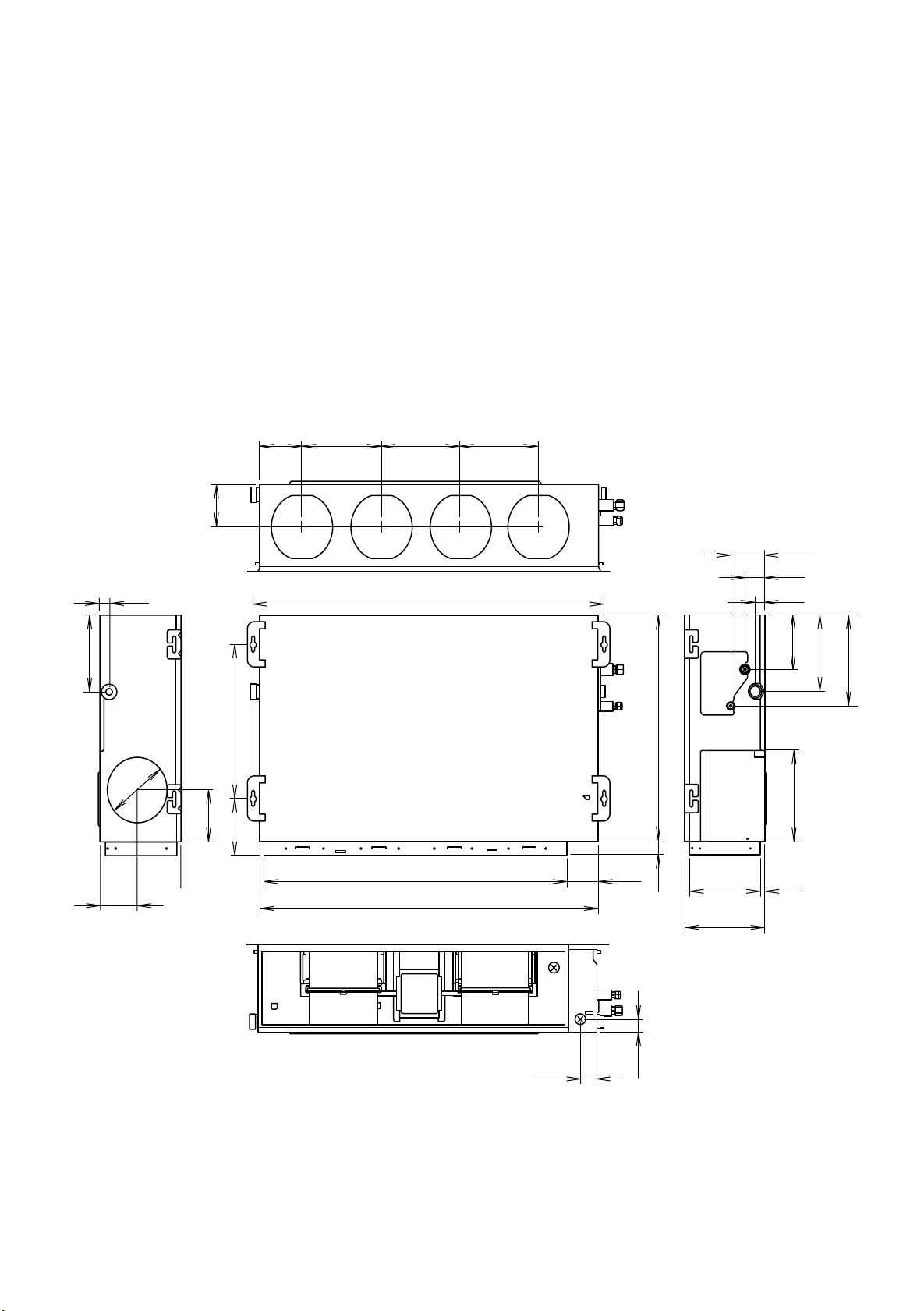
DIMENSIONS
INDOOR UNIT
(Unit : mm)
139
132
32
240
477
161
173
121
264 264 264
1,177
1,015
1,135
107
114
66
32
168
281
240
700
283
40
240
270
16
2006.09.29 2
54
39
Page 4
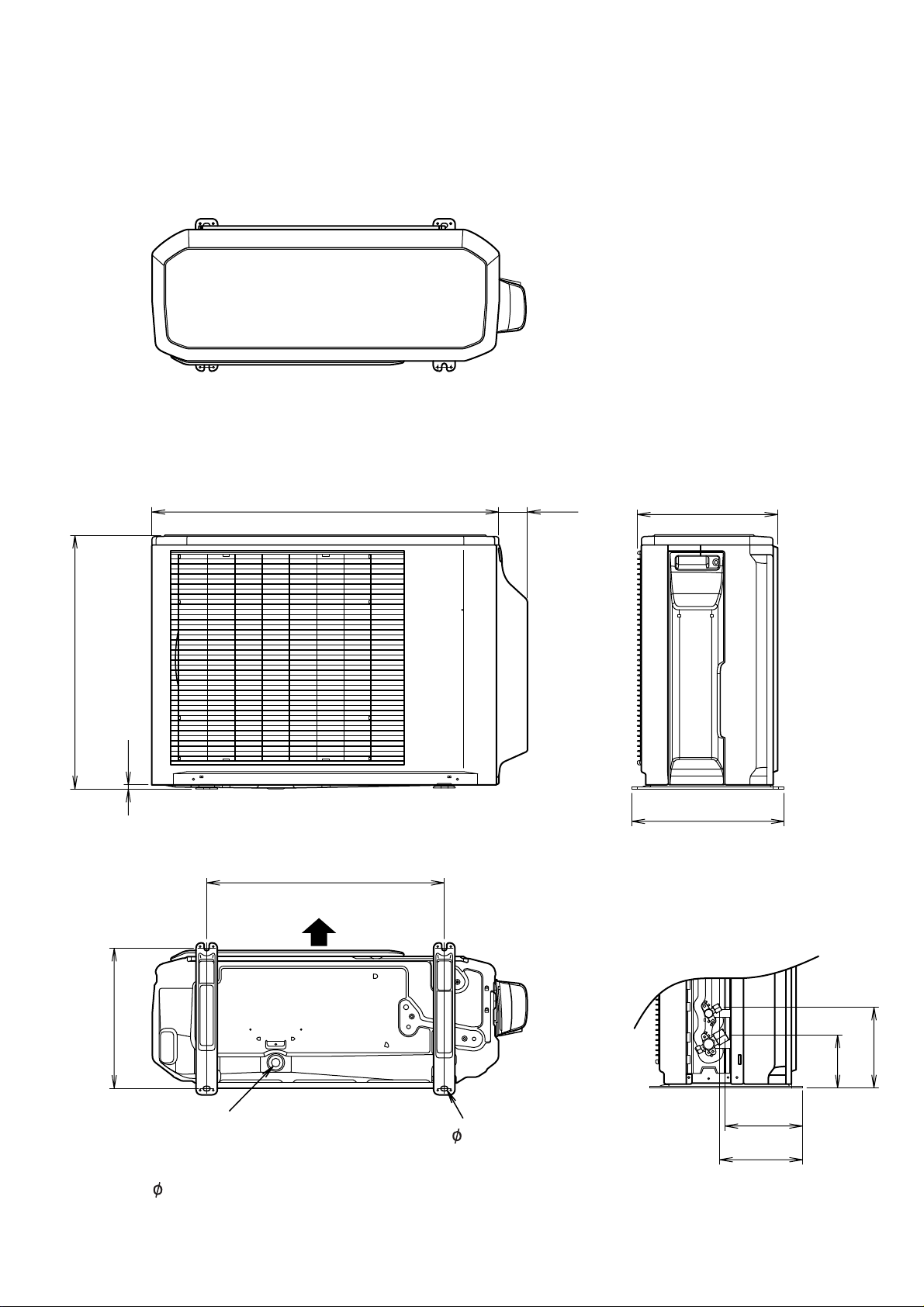
OUTDOOR UNIT
Unit : mm
Top view
31566790
578
10
347
Front view
Side view
540
Air flow
320
184
121
Drain pipe
Bottom view
4- 10mm hole
mounting place
( 20)
2006.09.29 3
177
189
Page 5
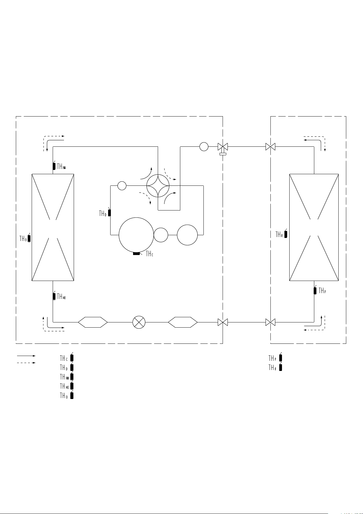
REFRIGERANT SYSTEM DIAGRAM
OUTDOOR UNIT
Heat exchanger
INDOOR UNIT
Muffler
3-Way
valve
Muffler
4-Way
valve
Heat exchanger
Accumulator
Compressor
Cool
Heat
: THERMISTOR (COMPRESSOR TEP.)
: THERMISTOR (DISCHARGE TEP.)
: THERMISTOR (HEAT EXCHANGER MED TEP.)
: THERMISTOR (HEAT EXCHANGER OUT TEP.)
: THERMISTOR (OUTDOOR TEP.)
Refrigerant pipe diameter
Liquid : 1/4" (6.35 mm)
Gas : 5/8" (15.88 mm)
Expansion
valve
StrainerStrainer
2-Way
valve
: THERMISTOR (PIPE TEP.)
: THERMISTOR (ROOM TEP.)
2006.10.23 4
Page 6
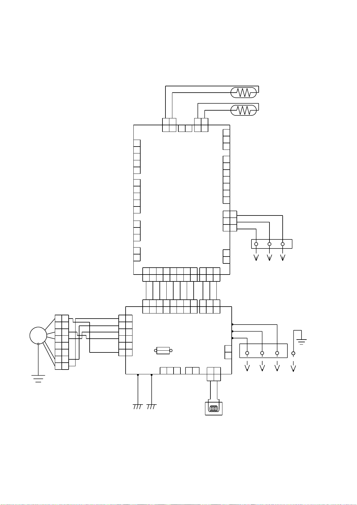
CIRCUIT DIAGRAM
INDOOR UNIT
GRAY
GRAY
1 2
1 2
CN5 CN7
1
2
3
CN12
4
5
CONTROLLER PCB ASSY
1
2
3
4
5
1
2
3
1
2
( MAIN PCB )
CN11
CN9
CN10
CN4 CN1
1 234 567 8
1 234 567 8
1 2
1 2
1 2
CN8
BLACK
BLACK
1 2
1 2
PIPE TEMPERATURE
THERMISTOR
ROOM TEMPERATURE
THERMISTOR
1
2
CN3
3
1
2
3
4
5
6
7
RED
1
1
WHITE
2
2
CN14 CN13
BLACK
3
3
TERMINAL
3
2
1
1
2
CN6
3
3
TO REMOTE CONTROL UNIT
( OPTION )
FAN
MOTOR
F M
GREEN /
YELLOW
GRAY
GRAY
GRAY
GRAY
GRAY
GRAY
1 234 567 8
1 234 567 8
1
1
2
2
3
3
4
4
5
5
6
6
7
7
8
8
BROWN
YELLOW
WHITE
BLACK
RED
1
1
2
2
3
3
4
4
CN105
5
5
6
6
E101
GREEN
CN104
POWER SUPPLY
PCB ASSY
FUSE 3.15A
CN102 CN103 CN108
E102
GREEN
1 2
3
GRAY
GRAY
GRAY
GRAY
1 2
1 2
CN101
250V
1 2 1 2
1 2
WHITE
GRAY
3
3
W105
W102
W101
CN106
WHITE
RED
WHITE
BLACK
1
2
1
TO OUTDOOR UNIT
2
TERMINAL
3
COIL
2006.10.25 5
Page 7
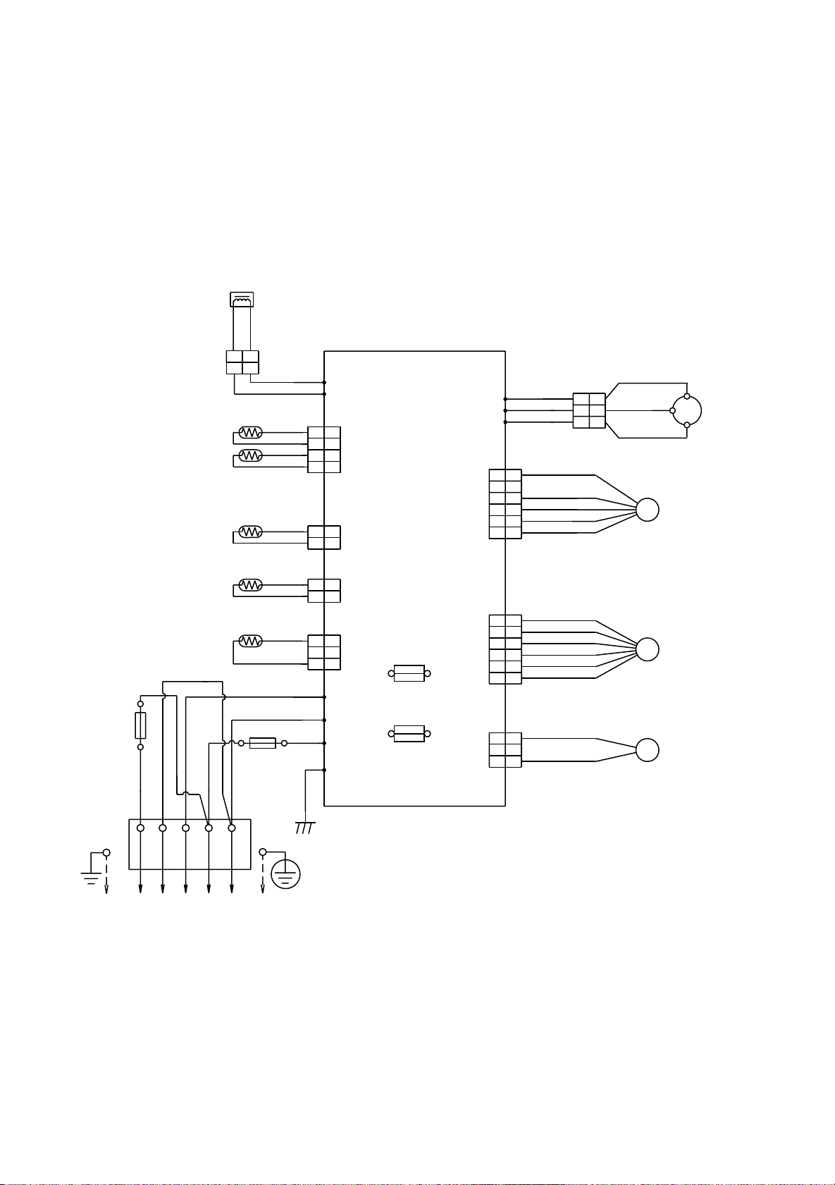
OUTDOOR UNIT
PIPE TEMPERATURE
THERMISTOR
DISCHARGE PIPE
TEMPERATURE THERMISTOR
COMPRESSOR
TEMPERATURE THERMISTOR
PIPE ( MID )
TEMPERATURE THERMISTOR
OUTDOOR TEMPERATURE
THERMISTOR
WHITE
FUSE 250V 5A
BLACK
BLACK
REACTOR
YELLOW
YELLOW
12
2
1
FUSE 250V 20A
BLACK
RED
WHITE
BLACK
BLACK
BROWN
BROWN
BROWN
BROWN
BLACK
BLACK
BLACK
BLACK
WHITE
BLACK
W10
W11
1
1
2
2
CN71
3
3
4
4
121
CN73
2
CONTROLLER PCB ASSY
CN72
CN70
( MAIN PCB )
FUSE
15A 250V
FUSE
3.15A
250V
RED
GREEN
121
1
2
3
2
1
2
3
W4
W2
W1
W3
S (S)
F M
FAN MOTOR
EXPANSION
PMV
VALVE
4WV
VALVE
R (R)
C M
RED
W7
W8
W9
CN801
CN40
CN30 4-WAY
RED
WHITE
BLACK
RED
1
1
2
2
BLACK
3
3
WHITE
4
4
YELLOW
5
5
BLUE
6
6
RED
1
1
BROWN
2
2
BLUE
3
3
ORANGE
4
4
YELLOW
5
5
WHITE
6
6
BLACK
1
1
2
2
BLACK
3
3
1
1
2
3
WHITE
2
3
BLACK
COMPRESSOR
C (T)
TERMINAL
2
1 3 L
N
( N )
TO INDOOR UNIT
POWER SOURCE
2006.11.14 6
Page 8

INDOOR PCB CIRCUIT DIAGRAM
INVERTER ASSEMBLY
EZ-00605HSE
CN8-1
CN8-2
CN7-1
CN7-2
CN5-1
CN5-2
CN8
B2B-XASK-1-A
CN7
B2B-XAYK-1-A
CN5
B2B-XAKK-1-A
ROOM TEMPERATURE THERMISTOR
GRAY
GRAY
PIPE TEMPERATURE THERMISTOR ( ENTRANCE )
PIPE TEMPERATURE THERMISTOR ( MID )
BLACK
BLACK
DC FAN MOTOR
NORMAL COIL
RLEY41-18
18A 22mH
OUTDOOR UNIT
F M
1
2 (N)
3
TERMINAL BOARD
UL1015 AWG16 GREEN
UL1015 AWG16 GREEN
CN105
B5P6-VH-B
RED
1
2
BLACK
3
WHITE
4
YELLOW
5
BROWN
6
7
8
CN106
B2P3-VH-B-E
DRAIN PUMP
CN103
B2B-XH-AM
EIB OUT
CN102
B3B-XH-AM
EIB I N
CN108
B2P3-VH-B
UL1015 AWG20 RED
UL1015 AWG20 WHITE
UL1015 AWG20 BLACK
E101
E102
CN105-6
CN105-5
CN105-4
CN105-3
CN105-2
CN105-1
BLUE
CN106-1
CN106-2
CN103-1
CN103-2
CN102-1
CN102-2
CN102-3
CN108-1
CN108-2
W101
W102
W105
POWER SUPPLY PCB ASSEMBLY
K06AL-0603HSE-P0
CN104-1
CN104-2
CN104-3
CN104-4
CN104-5
CN104-6
CN104-7
CN104-8
CN101-1
CN101-2
CN101-3
POWER DRIVE
CN104
B08B-PASK-1
CN101
B03B-PASK-1
EMI FILTER
ZCAT1518-0730
2 TURNS
B08B-PASK-1
GRAY
GRAY
GRAY
GRAY
GRAY
GRAY
GRAY
GRAY
DC SUPPLY
B03B-PASK-1
GRAY
GRAY
GRAY
CN4
CN1
CONTROLLER PCB ASSEMBLY ( MAIN PCB )
K06AK-0605HSE-C1
CN4-1
CN4-2
CN4-3
CN4-4
CN4-5
CN4-6
CN4-7
CN4-8
CN1-1
CN1-2
CN1-3
CN13-1
CN13-2
CN13-3
CN13-4
CN13-5
CN13-6
CN13-7
CN14-1
CN14-2
CN14-3
CN6-1
CN6-2
CN10-1
CN10-2
CN9-1
CN9-2
CN9-3
CN13
B07B-PASK-1
INDICATOR UNIT
CN14
B3B-XAKK-1-A REMOTE CONTROL UNIT
UL1430 AWG22 RED
UL1430 AWG22 WHITE
UL1430 AWG22 BLACK
CN6
B02B-PAMK-1
FRESH AIR
2
3
CN10
B02B-PAOK-1
HEATER
ERATH WIRE
REMOTE CONTROL UNIT
CN9
B03B-XARK-1-A
FLOAT SWITCH
TERMINAL BOARD
1
2006.09.29 7
Page 9

CONTROLLER PCB ASSEMBLY
K06AK-0605HSE-C1
IC1
UPD78F0535GK
(R)-012-UET-A
2006.09.29 8
Page 10

POWER SUPPLY PCB ASSEMBLY
K06AL-0603HSE-P0
W101
BLACK
W102
WHITE
I C26-10
I C26-14
F101
3.15A - 250V
<mT3>
FH101
FH102
VA101
470V
<TNR>
N
L
SA101
RA-362M
E101
GREEN
C101C
0.15
<RE>
C101B
0.22
<R41>
C101A
<R46>
VA102
470V
<TNR>
0.47
C101
0.6
<R46>
C101D
0.22
<LE>
C102
0.01
<KH>
C103
0.01
<KH>
LF101
ELF20N030A
1
2
4
3
C104C
0.15
<RE>
C104B
0.22
<R41>
C104A
0.47
<R46>
C104
0.6
<R46>
C104D
0.22
<LE>
C105A
0.022
<YE>
C106A
0.022
<YE>
C105
0.047
<R41>
C106
0.047
<R41>
NORMAL COIL
CN108
B2P3-VH-B
2
1
E102
GREEN
3
D101N
D5SBA60
2
3
D101
1
D3SB60
4
C108
4700P
15V
+
<RS-2W>
D102
R110
10K
<1/10W>
R103
62K
ZFT22801
2
3
5
6
7
8
D106
D1FL20U
C110 0.047 <ECQB>
D103
D1FL20U
D104
MTZJ5.1B
R109
<1/4W>
D1FL20U
330
+
T101
D105
C111
100/
25V
D108
D2FL20U
12
C113
1000/
10
A
25V
C114
0.01
<KH>
C115
0.01
<KH>
R108
100
<1/2W>
13.5V
R111
+
10K
<1/10W>
340V
CN107
B2P3-VH-B-Y
1
+
4
-
2
C107
C107A
+
390/
150/
450V
450V
C118
0.01
<KH>
1 2
C107B
+ +
270/
450V
CAPACITOR
<ECKW>
<RS-2W>
R106
<RS-2W>
C109
220P/
2.0kV
R105
1.5
75
Q101
2SC5354
2
3
2SC1815
R107
100
<1/10W>
1
Q102
1
R104
330K
<2W>
2
3
D107
RD16M
<B1>
<ECQM>
1SR139-600
C112
330/
25V
POWER DRIVE
B08B-PASK-1
SERIAL I N
SERIAL I NT
SERIAL ON
DRAIN PUMP
DC FAN-OUT
DC FAN-FEEDBACK
EX. SIGNAL-OUT
EX. SIGNAL-I N
DC SUPPLY
CN104
CN101
B03B-PASK-1
K101
G5N-1A
3
1
K101A
FTR-F3
CN105
B5P6-VH-B
6
5
4
3
2
1
<1/10W>
4
2
4
2
I C101
TLP621
<GB>
4
3
BLm11
<A601>
DC FAN MOTOR
R113
330
13.5V
1
3
L102
BLm11
5V
<A601>
1
2
L103
I C102
TLP621
1
2
<GB>
R112
330
<1/10W>
4
3
C116
0.01
<B>
CN102
B3B-XH-AM
3
2
1
2
1
E I B I N
W105
CN103
B2B-XH-AM
8
RED
SERIAL
E I B OUT
VA103
470V
<TNR>
IC26-14
7
L
IC26-14
L
IC26-10
N
IC26-10
I C 105
101418
6
N
K102
G5N-1A
3
1
K102A
FTR-F3
2
4
5 4 3 2
5 4
13.5V
2
4
RC101
1
3
120/
0.2
3 2 1
1
5V
CN106
B2P3-VH-B-E
2
1
DRAIN PUMP
C119
0.01
<KH>
I C103
TLP621
<GB>
4
3 2
340V
15V
1
A
R114
4.7K
<1/10W>
R115
6.8K
<1/4W>
15V
5V
1
2
3
4
5
6
7
8
1
2
3
1
2
TLP621
I C104
<GB>
15V
4
3
R116
1.0K
<1/4W>
R117
<1/4W>
5V
C121
0.1
<F>
820
+
C117
100/
25V
AA
13.5V
C120
0.1
<F>
2006.09.29 9
Page 11

OUTDOOR PCB CIRCUIT DIAGRAM
CONTROL UNIT
EZ-006AHUE
TO INDOOR UNIT
POWER SOURCE
AC220 - 240V
50Hz
SERIAL
L
N
1
2
3
4
5
TERMINAL
EMI FILTER
ATFC-25-15-12
W103
UL1015 AWG20
BLACK
W100
UL1015 AWG20
WHITE
W102
UL1015 AWG20 BLACK
W101
UL1015 AWG14
BLACK
F202
5A - 250V
F201
20A - 250V
2 TURN
DISCHARGE TEMPERATURE THERMISTOR
PIPE TEMPERATURE THERMISTOR
OUTDOOR TEMPERATURE THERMISTOR
EMI FILTER
ATFC-25-15-12
1 TURN
EARTH
UL1015 AWG14
BLACK
UL1015 AWG14
WHITE
UL1015 AWG20
RED
UL1015 AWG16
GREEN
BLACK
BLACK
BROWN
BROWN
BLACK
BLACK
B
W1
( A-1 )
B
W2
( B-1 )
B
W4
( D-1 )
B
W3
( C-1 )
1
CN71
2
B04B-PASK-1
3
WHITE
4
1
CN70
2
B03B-PASK-1
WHITE
3
REACTOR
UL3271 AWG16
WHITE
UL3271 AWG14
RED
W10 W11
B B
CONTROLLER PCB ASSEMBLY
( MAIN PCB )
K06AX-0601HUE-C1
CN30
B2P3-VH-B-C
BLACK
CN801
B5P6-VH-B-L
WHITE
W7
B
W8
B
B
W9
1
2
3
1
2
3
4
5
6
U
RED
V
WHITE
W
BLACK
UL3271 AWG16 x 3
BLACK
BLACK
RED
BLACK
WHITE
YELLOW
BROWN
EMI FILTER
RED
WHITE
BLACK
4-WAY VALVE
F M
COMPRESSOR
C M
DC FAN MOTOR
COMPRESSOR TEMPERATURE THERMISTOR
PIPE ( MID ) TEMPERATURE THERMISTOR
BROWN
BROWN
BLACK
BLACK
CN73
1
B02B-XAMK-1-A
2
GREEN
1
CN72
B02B-XH-AM
2
WHITE
2006.09.29 10
CN40
B6B-XARK-1-A
RED
1
2
3
4
5
6
RED
BROWN
BLUE
ORANGE
YELLOW
WHITE
EXPANSION VALVE MOTOR
M
Page 12

CONTROLLER PCB ASSEMBLY
K06AX-0601HUE-C1
POWER SOURCE
AC230V
50Hz
1 2
4 3
L1
10 - 60
16 - 75
H Y I C 1
HU2001
R119
10K
1%
R134
R133
10K
10K
1%
2
3
502
1.0K
C503
0.1
<F>
-
1
+
I C104-1
BA2902F
13
-
12
+
I C104-4
BA2902F
5V
R503
10K
R561
C561
0.01
<F>
1%
14
1.0K
12V
I C40
TD62064
2
7
9
16
GND1
4
5
12
13
C11
0.1
<F>
3
2
6
-
5
+
I C10-2
BA2903F
12V
R135
10K
1%
R141
10K
1%
500
1.0K
I C500
MB90460
17
P63
VCC
56
AVCC
11
P62
16
2
P00
25
P46
35
3
59
58
60
21
34
47
27
5V
15V
+
1
-
7
I C80
uLN2003
1C
1B
1
2C
2
2B
3
3B
3C
4C
4
4B
5
5B
5C
6B
6
6C
7B
7
7C
8B
9
8
COM
E
C500
0.1
<F>
12V
16
15
14
13
12
11
10
28
29
30
31
32
33
57
41
42
43
44
10
9
8
7
5
6
4
22
23
1
3
2
P12
P50
P37
P36
P40
MD2
P11
AVR
P26
P02
P03
P04
P05
P06
P07
P10
C
P20
P21
MD0
P22
MD1
P23
P57
P56
P55
P54
RSTX
P52
P53
AGND
P51
X0
GND
X1
GND
X500
8.00MHz
<CSTS>
26
P01
P17
40
P13
36
37
P14
38
P15
39
P16
12
45
P24
46
P25
50
P30
51
P31
52
P32
53
P33
54
P34
55
P35
P60
14
15
P61
18
20
P44
64
P43
63
P42
62
P41
61
P45
1
19
P27
48
13
24
49
C502
+
0.1
<F>
C501
10/25V
2006.09.29 11
R164
22K
C111
4700P
<B>
C125
0.1
<F>
15V
-12V
R560
100K
5V
+
-
5V-2
R116
15K
1%
R117
22K
1%
C115
0.1
<F>
C116
0.1
<F>
5V
C135
1000P
<B>
R168
22K
RESET
2
VDD
1
OUTNCGND
I C560
S80842
5
4
R170
68K
R115
22K
1%
+
2
I C102-1
BA2901F
R165
22K
+
-
5V-2
C131
<F>
3
4
R112
10K
1%
C110
0.1
<F>
0.1
R581
10K
15V
14
I C102-3
BA2901F
15V
C112
0.1
<F>
5V
C128
0.1
<F>
R169
22K
C133
C132
+
2.2/
50V
R585
R93, R92, R91, R90
1.0K
R582
10K
2.2/
50V
+
R583
1.0K
10K x 4
+
-
9
8
C134
0.1
<F>
D112
DAN217U
5V
R584
22K
BR93LC46
CS1
2
SK
3
D I
6
NC
5V
C580
0.1
<F>
I C570
R570
10K
GND
VCC
DO
NC
D113
DAN217U
5V
5V
8
4
7
5
JM101
JM102
JM103
JM100
C570
0.1
<F>
DCV
TEST
DCV-F
UDZS8.2B
BLm31
<A601>
BLm31
<A601>
DCV
DAN217U
D50
1SS355
D51
L50
L51
D52
1SS355
R51
C50
35V
D305
47
47/
15V
<1/8W>
<1/8W>
<1/8W>
<1/8W>
+
5V
Q300
DTC114EUA
DCV-F
R52
470K
1%
R53
510K
1%
R54
510K
1%
R55
510K
1%
C51
1.0
<B>
R56
150K
<2W>
5V
C300
100P
<CH>
2200P
UF4005
I C50
TOP243P
1
M
2
S
3
S
4
C
1
<1/16W>
<1/10W>
C52
<E>
R57
0R0
D53
S
S
D
-
+
R83
27K
8
7
5
2
3
R81
1.0K
5V 5V
5V
7
I C302-2
BA2903F
RPZ-1F
1
2
3
4
5
JM1
T60
15V
L300
ELC0507RA
U
V W
W7W8W9
I C200
FSBS20CH60
C214
2200P
<B>
IPM-G
15V
IPM-G
C305
0.1
<F>
DAN217U
3 3
C64
+
330/
25V
D63
1SS355
I
+
D303
21
C69
100/
25V
-12V
1
OG123
2
-
1
3
+
-
+
C85
10/
25V
6
-
5
+
10
+
5
7
-
6
C330
1000P
<B>
15V
D304
DAN217U
C86
<B>
D60
D1FL20U
D61
D1FL20U
C66
100/
25V
D64
1SS355
C87
330P
<B>
+
2
I C60
BA7805
+
470P
C84
0.1
<F>
9
8
7
6
D62
D1FL20U
1
2
3
4
5
6
7
8
9
10
11
12
13
14
15
16
17
18
19
20
C306
0.1
<F>
R309
5.76K
1%
R310
143
1%
VCC
COM
I N
I N
I N
VFO
CFOD
CSC
I N
VCC
VB
VS
I N
VCC
VB
VS
I N
VCC
VB
VS
+
R210
1.0K
C65
470/
25V
21
NU
22
NV
23
NW
U V W
24
U
25
V
26
W
27
P
DCV
R211
R212
R213
R214
R215
C218
0.1
<HCP>
R216
R217
0.15
<1W>
1%
x 7
R307 195K
<RN-1/2W>
R308 195K
<RN-1/2W>
R311
8.66K
1%
15V
12V
R61
5V
1.0K
C67
0.1
<F>
C68
+
100/
25V
-12V
Page 13

ERROR CONTENTS
REMOTE CONTROL UNIT
Troubleshooting at the remote control LCD
This is possible only on the wired remote control.
[ SELF-DIAGNOSIS ]
If an error occurs, the following display will be shown.
("EE" will appear in the set room temperature display.)
Unit number
Error code
SUMOTUWETH FR
SA
Ex. Self-diagnosis
Code Error contents
01
13
26
Indoor signal error
27
00
02
04
28
09
0C
06
0A
15
1d
1E
29
20
2A
17
18
1A
1b
1F
1c
12
0F
24
2c
16
2b
19
25
Wired remote controller abnormal
Indoor room temperature sensor error
Indoor heat exchanger temperature sensor (middle) error
Indoor heat exchanger temperature sensor (inlet) error
Float switch operated
Outdoor discharge pipe temperature sensor error
Outdoor heat exchanger temperature sensor (outlet) error
Outdoor temperature sensor error
Compressor temperature sensor error
2-way valve temperature sensor error
3-way valve temperature sensor error
Outdoor heat exchanger temperature sensor (middle) error
Indoor manual auto switch abnormal
Power supply frequency detection error
IPM protection
CT error
Compressor location error
Outdoor fan error
Connected indoor unit abnormal
Outdoor unit computer communication error
Indoor fan abnormal
Discharge temperature error
Exessive high pressure protection on cooling
4-way valve abnormal
Pressure switch abnormal
Compressor temperature error
Active filter abnormal
PFC circuit error
If "CO" appears in the unit number display, there is a remote controller
error. Refer to the installation instruction sheet included with the remote
controller.
2006.10.23 12
Page 14

OUTDOOR UNIT
Error contents
Thermistor malfunction
Abnormal discharge temperature
Current surge protection
CT abnormality
Compressor position detection malfunction
Fan malfunction
PAM voltage abnormality
Timer short
Compressor temperature protection (permanent stop)
PFC surge protection (permanent stop)
LED
on 0.1 sec / off 0.1 sec
on
on 0.5 sec / off 0.5 sec
on 2.0 sec / off 2.0 sec
on 0.1 sec / off 2.0 sec
on 5.0 sec / off 5.0 sec
on 5.0 sec / off 0.1 sec
on 1.0 sec / off 0.1 sec
on 2.0 sec / off 5.0 sec
on 5.0 sec / off 2.0 sec
2006.10.23 13
Page 15

DISASSEMBLY ILLUSTRATION
INDOOR UNIT
74
324
160
Insulation
73
20
70
764
146
75
Control Box
Insulation
325
2006.10.23 14
72
Insulation
Page 16

INDOOR UNIT
55
67
138
56
108
42
41
43
43
2006.10.23 15
67
164
150
Page 17

INDOOR UNIT
236
287
817
816
288
875
2006.10.25 16
900
Page 18

OUTDOOR UNIT
9
14
38
37
5
22
13
19
41
20
35
40
11
32
37
10
15
3
36
21
39
1
18
2
34
16
17
2006.10.25 17
6
7
4
Page 19

OUTDOOR UNIT
26
30
42
29
28
27
2006.10.25 18
Page 20

PARTS LIST
INDOOR UNIT
Ref.
No.
20 Control Cover-A Sub Assy 9374516018
41
42 Bracket Motor Assy B 9358591000
43 Bracket Motor C 9358594001
55 Casing B 9374234011
56 Sirocco Fan Assy 9356531039
67 Rubber 9385102002
70 Bracket (pipe) Sub Assy
72 Cabinet-L Sub Assy 9374509010
73 Cabinet-R Sub Assy 9374508013
74 Intake Cover Sub Assy
75 Outlet Panel Sub Assy 9374510016
108 Base Sub Assy
138 Separate Wall Assy
146 Evaporator Assy 9374518012
150 Bracket (Eva. )-R 9374207015
160 Drain Pan Sub Assy 9374513017
164 Motor, Induction 9602433018
236 Controller PCB Assy 9707393064
287 Cap (Power) 9352173011
Description
Bracket Motor Assy A 9374230020
Part No.
ARHA24LATN
9374514014
9374512010
9374504015
9374228010
Ord.
Q'ty
288 One Touch Bush 9374407019
324 Main Panel Sub Assy
325 Intake Frame Assy 9374216017
764 Drain Cap 9356541007
816 Terminal-3P
817 Terminal-3P 9306489045
875 Power Supply PCB Assy 9707398045
900 Reactor Assy
---- Thermistor Spring-A 313728262708
---- Room Temperature Thermistor 9703299025
---- Pipe Temperature Thermistor 9703297021
---- Bracket (Eva. )-L 9374208012
2006.10.27 19
9374511013
9703345012
9707457018
When you order parts, please make a photocopy of this page and
fill the number of the parts in the "Order" column.
Page 21

OUTDOOR UNIT
Ref.
No.
Description
1 Top Panel Assy
2 Top Panel Seal
3 Cabinet Assy
4 Blow Down Grille
5 Cabinet Right Assy
6 Fan Ring
7 Grip
9 Protective Net
10 4-Way Valve
11 Pulse Motor Valve Assy
13 Condenser Assy
14 Thermistor Spring-A
15 Thermistor Spring
16 Propeller Fan
17 Nut
18 Motor Bracket
19 Separator Assy
20 Base Assy
21 3-Way Valve Assy
22 2-Way Valve Assy
Part No.
AOHA24LACL
9309230057
9309228016
9314809019
9308884015
9309236028
9308885012
9308880017
9315033017
9900163013
9315310019
9315302014
313728262708
9300089012
9309909014
9304902003
9308872029
9312971015
9315296030
9315414014
9313062019
Ord.
Q'ty
26 Inverter PCB Assy
9707427028
27 Fuse Holder 0501454012
28 Fuse Holder 0501456016
29 Fuse
0600382018
30 Fuse 0600372163
32 Expansion Valve Coil
34 Fan Motor
35 Compressor Assy
36 Emblem
Thermistor Assy37
38 Heat Exchanger Thermistor
39 Solenoid Coil
40 Compressor Thermistor
Reactor Assy
41
Terminal42
Outdoor Temp. Thermistor---
9900057039
9602451012
9315297037
9315211019
9900148027
9900403010
9970055010
9900156046
9900354015
9703874031
9900210045
--- Distributor 9315387011
--- Condenser Assy B 9315303011
2006.11.14 20
When you order parts, please make a photocopy of this page
and fill the number of the parts in the "Order" column.
Page 22

STANDARD ACCESSORIES
The following installation parts are furnished. Use them as required.
INDOOR UNIT ACCESSORIES
Name and Shape
Hanger
Q'ty
Application
For suspending the indoor
unit from ceiling
4
Special nut A
(large flange)
Special nut B
(small flange)
Coupler heat
insulation (large)
For suspending the indoor
unit from ceiling
4
4
For indoor side pipe joint
(large pipe)
1
Coupler heat
insulation (small)
For indoor side pipe joint
(small pipe)
1
OUTDOOR UNIT ACCESSORIES
Name and Shape Q'ty Application
Binder
For fixing the drain hose
1
(large)
Drain hose insulation
Insulates the drain hose
and vinyl hose
1
Name and Shape
Drain pipe
Q'ty
For outdoor unit drain piping work.
Part No.Application
9303029015
1
OPTIONAL PARTS
When connecting the square duct and round duct, use the optional square flange or round flange and flexible duct.
Square flange Round flange
Model name : UTD-SF045T (P/N 9098180007) Model name : UTD-RF204 (P/N 9093160004)
40 mm
205 mm
195 mm
204 mm
1065 mm
Flexible duct Long-life filter
Model name : UTD-RD202 (P/N 9074165004) Model name : UTD-LF25NA (P/N9079892004)
85 mm
22
5
mm
mm
5
23
200 mm
L 2 m
Remote sensor
Model name : UTD-RS100 (P/N9072619004)
2006.09.29 21
239 mm
507 mm
Page 23

0610G3150
 Loading...