

Page 1
R410A
INDOOR UNIT
1. DUCT
AR A18LALU
AR F18LALU
TYPE :
D2D_AR029E/04
2008.04.14
Page 2
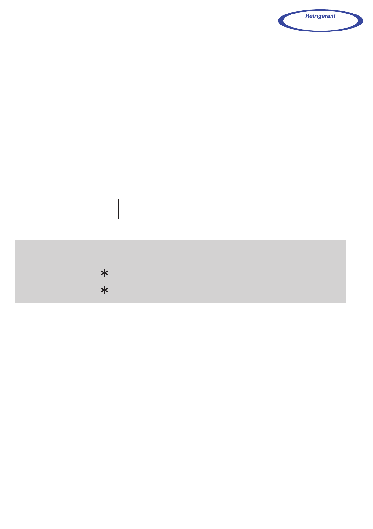
1. FEATURE
MODEL :
DUCT TYPE
AR A18L
INDOOR UNIT
OUTDOOR UNIT
AR A18LALU AO A18LACL AO B18LACL
AR F18LALU AO A18LALL AO B18LALL
FEATURES
Energy saving (AO A18LACL, AO A18LALL connection model)
High energy saving was realized by making the indoor unit and outdoor
unit fan motor and compressor all DC and optimal design of the refrigerant cycle. Rank A was achieved in European energy rank.
Universal design indoor unit
Since vertical and horizontal installation is possible, and the intake direction can also be selected
from two directions, flexible installation is possible.
Ceiling concealed Floor concealed
DUCT TYPE
AR A18L
Thin and compact indoor unit
Quiet mode
Operation at *27dB(A) possible by Quiet Mode.
* See our measurement conditions page (01-16).
FUNCTION SETTING
Static pressure mode setting
Air flow, noise, etc. can be used under the optimum conditions by selecting
the static pressure mode matched to the installation conditions.
Room temperature adjustment correction
Suitable room temperature control is performed by changing the room temperature correction value
by simple remote control operation to match the conditions under which the air conditioner is installed.
Auto restart
The units restart automatically when the current was returned even when
there was a power interruption during operation.
- (01 - 01) -
Page 3
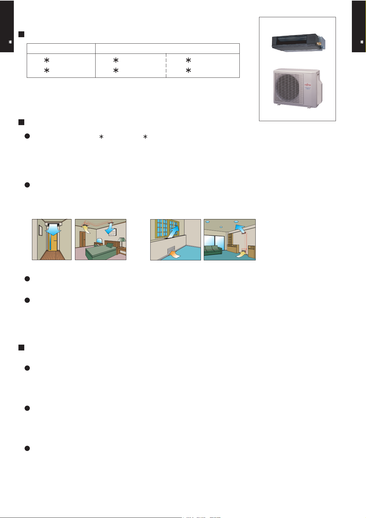
2. REMOTE CONTROLLER
WIRED REMOTE CONTROLLER
DUCT TYPE
AR A18L
FEATURES
Various timer setup (ON / OFF / WEEKLY) are possible.
Equipped with weekly timer as standard function.
(2 times Start / Stop per day for a week)
When setting up a timer, operation mode and a temperature
setup can be changed.
When a failure occurs,the error code is displayed. (Maximum of 16)
Error indication.(A maximum of 16 error histories are memorizable.)
Up to 16 indoor units can be simultaneously controlled.
Economy operation are possible.
Easy installation with a slim shape with no bulge in the back.
The room temperature can be controlled by being detected the temperature
accurately with built-in thermo sensor.
Simple function setting
Setting of the air conditioner selection function is performed by remote controller.
DUCT TYPE
AR A18L
High performance and compact size
Three functions are combined in
one unit.
Wired
remote
controller
Weekly
timer
Setback
timer
Built-in timers
Setback timerWeekly timer
Possible to set ON/OFF time to operate twice each day
of the week.
SUMOTUWETH FR SA
7
3126 9
15 18 21
Setup screen example
(Set to Wednesday: 8:00 to 20:00.)
0 3 6 9 12 15 18 21 Time
Easy-to-understand time bar display
24°C
SUMOTUWETH FR SA
7
3126 9
15 18 21
Screen
after setup
At "Weekly timer" + "Set back timer" setup
24°C 28°C 24°C
0 3 6 9 12 15 18 21 Time
Possible to set temperature for two time spans and
for each day of the week.
SUMOTUWETH FR SA
3126 9
Setup screen example
(Set from Sunday to Saturday: 12:00 to 15:00, 28 °C.)
0 3 6 9 12 15 18 21 Time
24°C
28°C
Easy-to-understand operation Simple installation
15 18 21
28°C
Timer
area
[
Variable timer control
]
Operation
area
The operation/display sections are zoned according to time and operation, enabling variable programming to match application.
- (01 - 02) -
Components are compatible with standard
switch boxes. Flat back construction allows
equipment to be installed wherever it is
needed.
European
switch box
JIS box
Page 4
DUCT TYPE
AR A18L
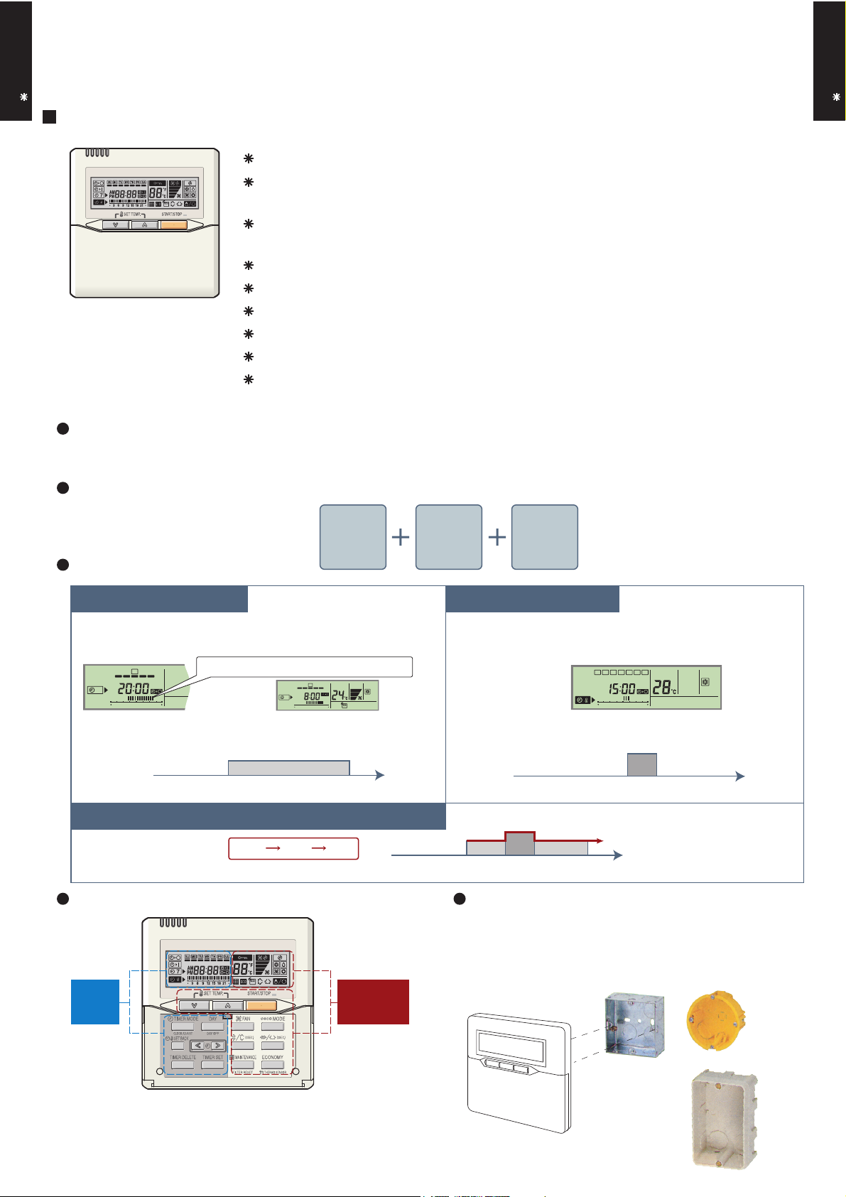
FUNCTIONS
2
6
7
8
9
10
11
Display panel
16
19
20
18
17
15
13
12
14
DUCT TYPE
1
START/STOP button
Pressed to start and stop operation.
2
Set temperature button
Selects the setting temperature.
3
Master control button
Selects the operating mode(AUTO, HEAT, FAN, COOL, DRY).
4
1
3
4
5
Fan control button
Selects the fan speed (AUTO, QUIET, LOW, MED, HIGH).
5
Economy button
Turns the economy efficient mode on and off.
6
Timer mode (CLOCK ADJUST) button
Selects the timer mode (OFF TIMER, ON TIMER, WEEKLY TIMER).
Set the current time.
7
Day (DAY OFF) button
Temporarily cancels of one day timer.
8
Set back button
Pressed to select the set back timer.
9
Set time button
Pressed to set time.
10
Delete button
The schedule of a weekly timer is deleted.
11
Set button
Sets the date, hour, minute and on-off time.
12
Vertical airflow direction and swing button*
Push for two seconds to change the swing mode.
13
Horizontal airflow direction and swing button*
Push for two seconds to change the swing mode.
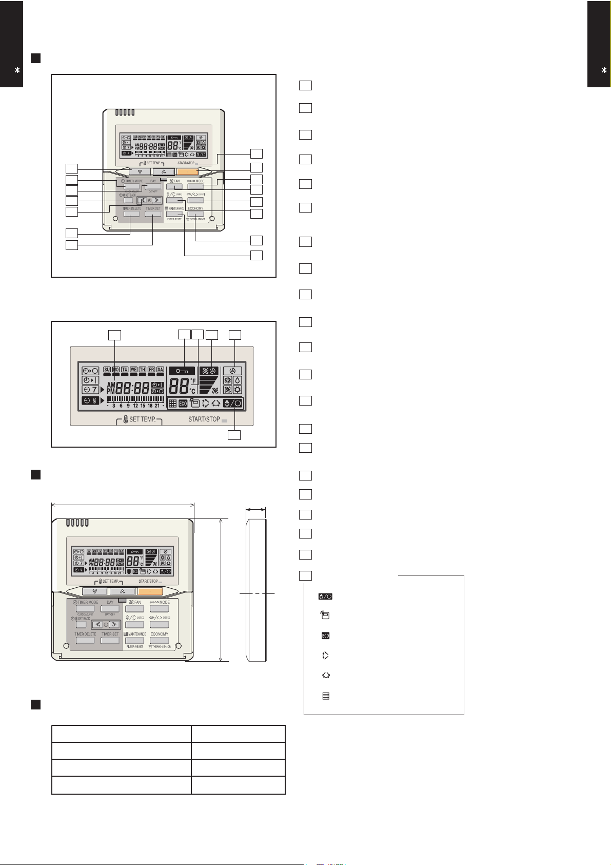
AR A18L
DIMENSION
120
Front View
SPECIFICATION
21
[ Unit : mm ]
120
14
Filter button*
15
Operation lamp
Lights during operation and when the timer is on.
16
Timer and clock display
17
17
Operation mode display
18
Fan speed display
19
Operation lock display
20
Temperature display
21
Function display
Defrost display
Thermo sensor display
Economy display
Vertical swing display*
Horizontal swing display*
Filter display*
SIZE (H x W x D mm) 120 x 120 x 17
WEIGHT ( g ) 160
CABLE LENGTH ( m )
POWER ( V )
10
12
*These functions are not available.
- (01 - 03) -
Page 5
DUCTED MODEL
INVERTER HEATPUMP
AR A18LALU, AR F18LALU
AO A18LACL, AO A18LALL
230V 50Hz
198-264V 50Hz
Cooling A
Heating A
kW 5.20
BTU/h 17700
kW 0.90 - 5.90
BTU/h 3100 - 20100
kW 6.00
BTU/h 20500
kW 0.90 - 7.50
BTU/h 3100 - 25600
1.62
2.16
1.66
2.96
7.1
9.0
7.3
12.5
EER 3.21
COP 3.61
l/h (pints/h) 2.0 ( 3.5 )
High 820
Med 720
Low 610
Quiet 550
High 820
Med 720
Low 610
Quiet 550
Type × Q'ty Sirocco × 2
Motor output W 60
Recommended static pressure Pa 0 to 90
High 33
Med 31
Low 29
Quiet 27
High 33
Med 31
Low 29
Quiet 27
Dimensions (H × W × D) 294 × 700 × 39.9
Fin pitch 1.30
Rows x Stages 3 × 14
Pipe type Copper
Fin type Aluminium
Material Steel
Colour
Net 217 × 953 × 595
Gross 324 × 1075 × 686
Net 23 ( 51 )
Gross 27 ( 60 )
Liquid 6.35 ( 1 / 4 in.)
Gas 12.70 ( 1 / 2 in.)
Method Flare
°C 18 to 32
%RH 80 or less
Heating °C 30 or less
Wired
PS
mm
Outer diameter 26.0 / Inner diameter 21.5
Type
mm
Rated
Min.-Max.
Rated
Min.-Max.
Rated
*Max.
Power source
Available voltage range
Capacity
Cooling
Heating
European energy label
kW/kW
Input power
Cooling
kW
Heating
Rated
*Max.
Current
Cooling
A
Rated
*Max.
Rated
*Max.
Cooling
Heating
Heating
Cooling
Moisture removal
Cooling
Heating
m3/h
Fan
Dimensions
( H×W ×D )
mm
Airflow
rate
Enclosure
Heat exchanger type
Sound pressure level
Heating
kg(lb.)
Connection pipe
Size
mm
Weight
Model name
dB(A)
Remote controller type
Drain pipe
Material
Size
Operation range
Cooling
3. SPECIFICATIONS
DUCT TYPE
AR A18L
DUCT TYPE
AR A18L
- (01 - 04) -
Note :
Specifications are based on the following conditions.
Cooling : Indoor temperature of 27 °CDB / 19 °CWB.and outdoor temperature of 35 °CDB/24°CWB.
Heating : Indoor temperature of 20 °CDB / 15 °CWB.and outdoor temperature of 7 °CDB/6 °CWB.
Standard static pressure : 0 Pa
Pipe length : 7.5 m, Height difference : 0 m.(Outdoor unit - Indoor unit)
Sound pressure level : Install a 2m duct to the outlet port and a 1m duct to the suction poit and measure.
The maximum current and the maximum input value are the maximum values when operated within the operation range (temperature).
Page 6
DUCT TYPE
AR A18L
DUCT TYPE
AR A18L
- (01 - 05) -
DUCTED MODEL
INVERTER HEATPUMP
AR A18LALU, AR F18LALU
AO B18LACL, AO B18LALL
230V 50Hz
198-264V 50Hz
Cooling B
Heating B
kW 5.20
BTU/h 17700
kW 0.90 - 5.70
BTU/h 3100 - 19500
kW 6.00
BTU/h 20500
kW 0.90 - 7.20
BTU/h 3100 - 24600
1.70
2.16
1.75
2.96
7.4
9.0
7.7
12.5
EER 3.06
COP 3.43
l/h (pints/h) 2.0 ( 3.5 )
High 820
Med 720
Low 610
Quiet 550
High 820
Med 720
Low 610
Quiet 550
Type × Q'ty Sirocco × 2
Motor output W 60
Recommended static pressure Pa 0 to 90
High 33
Med 31
Low 29
Quiet 27
High 33
Med 31
Low 29
Quiet 27
Dimensions (H × W × D) 294 × 700 × 39.9
Fin pitch 1.30
Rows x Stages 3 × 14
Pipe type Copper
Fin type Aluminium
Material Steel
Colour
Net 217 × 953 × 595
Gross 324 × 1075 × 686
Net 23 ( 51 )
Gross 27 ( 60 )
Liquid 6.35 ( 1 / 4 in.)
Gas 12.70 ( 1 / 2 in.)
Method Flare
°C 18 to 32
%RH 80 or less
Heating °C 30 or less
Wired
PS
mm
Outer diameter 26.0 / Inner diameter 21.5
Operation range
Cooling
Remote controller type
Drain pipe
Material
Size
Weight
kg(lb.)
Connection pipe
Size
mm
Heat exchanger type
mm
Enclosure
Dimensions
( H×W ×D )
mm
Sound pressure level
Cooling
dB(A)
Heating
Fan
Airflow
rate
Cooling
m3/h
Heating
Cooling
kW/kW
Heating
Moisture removal
Current
Cooling
Rated
A
*Max.
Heating
Rated
*Max.
Input power
Cooling
Rated
kW
*Max.
Heating
Rated
*Max.
Capacity
Cooling
Rated
Min.-Max.
Heating
Rated
Min.-Max.
Type
Power source
Available voltage range
European energy label
Model name
Note :
Specifications are based on the following conditions.
Cooling : Indoor temperature of 27 °CDB / 19 °CWB.and outdoor temperature of 35 °CDB/24°CWB.
Heating : Indoor temperature of 20 °CDB / 15 °CWB.and outdoor temperature of 7 °CDB/6 °CWB.
Standard static pressure : 0 Pa
Pipe length : 7.5 m, Height difference : 0 m.(Outdoor unit - Indoor unit)
Sound pressure level : Install a 2m duct to the outlet port and a 1m duct to the suction poit and measure.
The maximum current and the maximum input value are the maximum values when operated within the operation range (temperature).
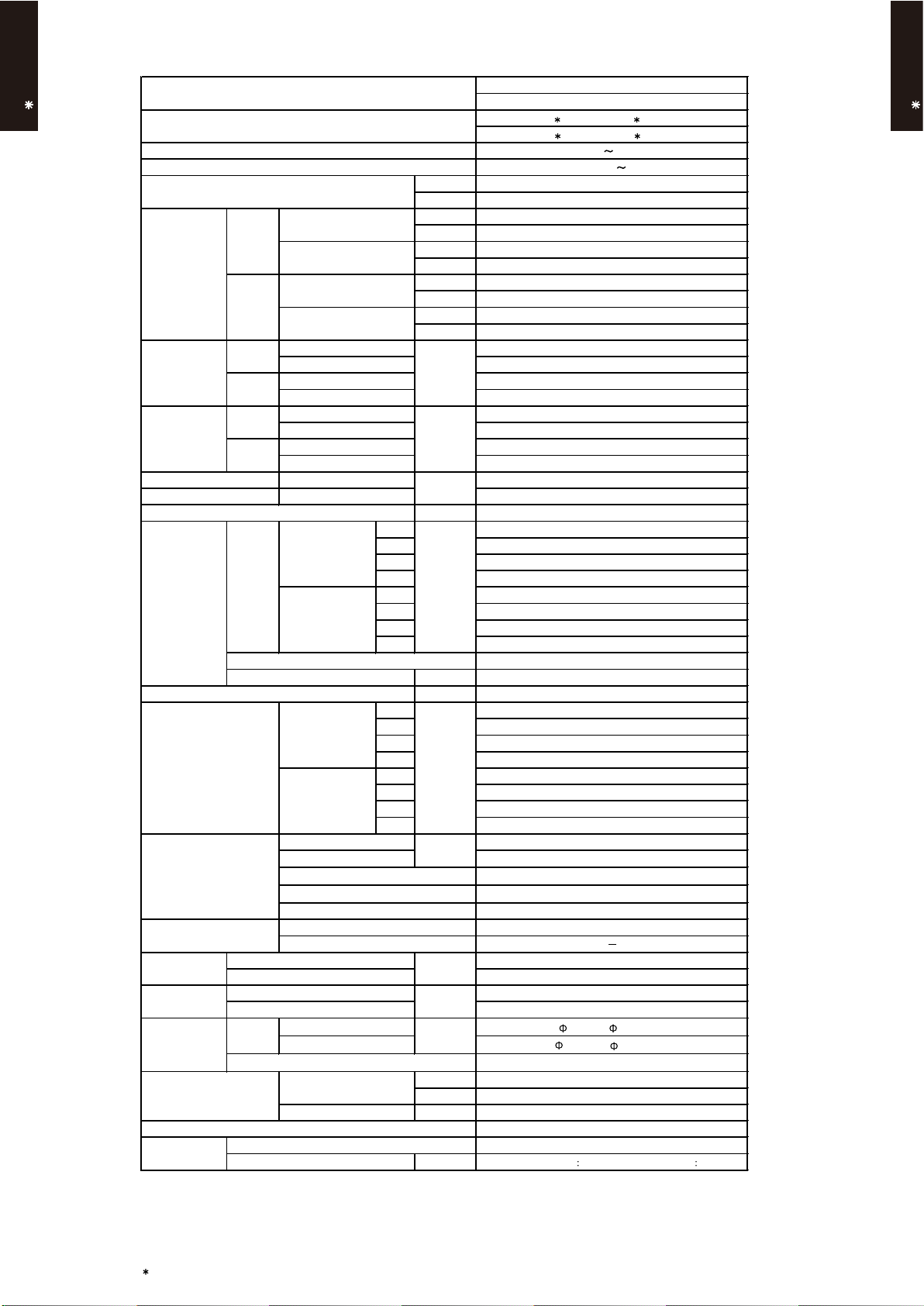
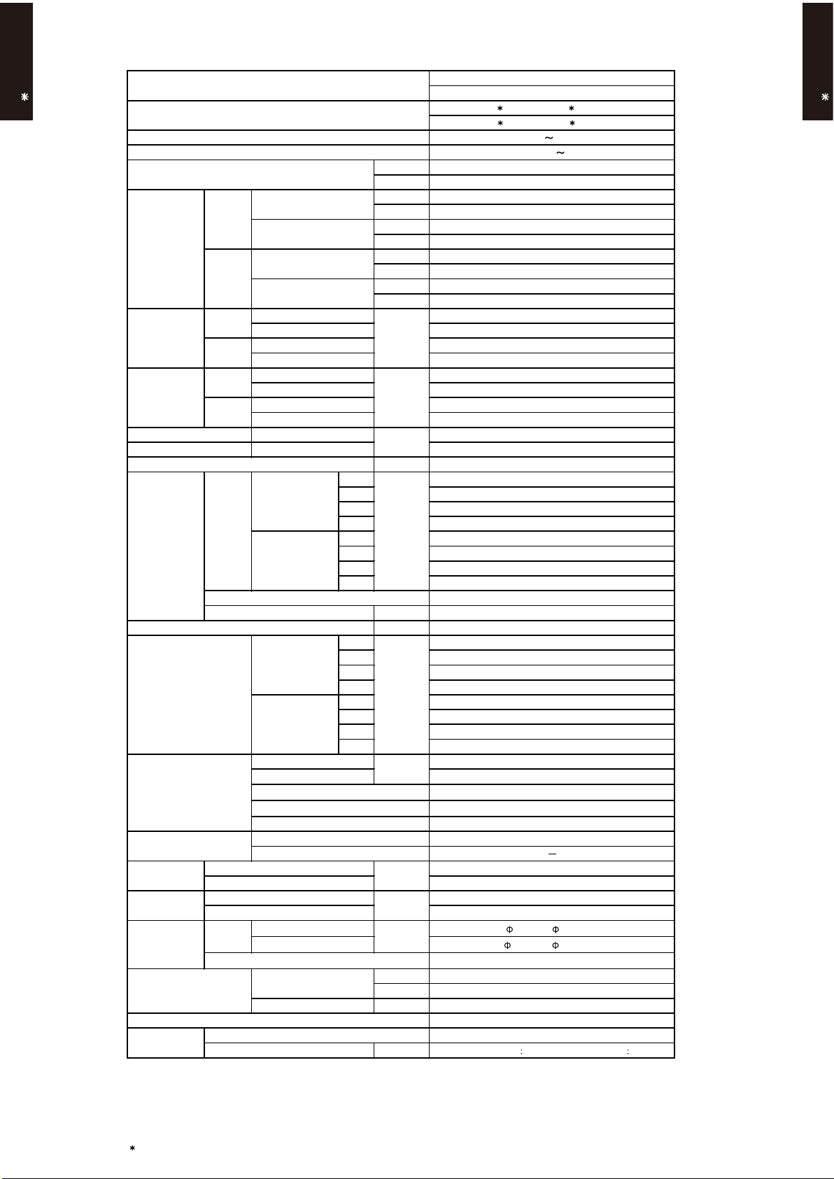
Page 7
4. DIMENSIONS
MODEL : AR A18L, AR F18L
DUCT TYPE
AR A18L
BRACKETS
AIR FLOW OUTLET
DRAIN PORT
COUPLING PIPE ASSY
886
850
CONTROL BOX
(Unit : mm)
DUCT TYPE
AR A18L
390
Top view
953
920
600
150
Front view
1
Refrigerant piping flare connection (Gas)
2
Refrigerant piping flare connection (Liquid)
3
Drain piping connection
1
2
12
595
57520
150
85 75
Side view
364
3
194
217
- (01 - 06) -
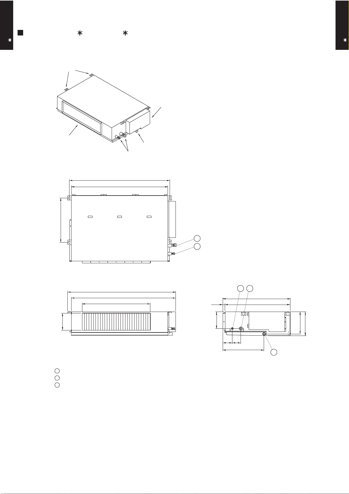
Page 8
DUCT TYPE
AR A18L
MOUNTING POSITION
Strong and durable ceiling
Indoor unit
(Unit : mm)
DUCT TYPE
AR A18L
Left
side
100 or more
Left
side
Strong and durable floor
100 or more 300 or more
Right side
(PIPE side)
Right
side
300 or more
30
or more30or more
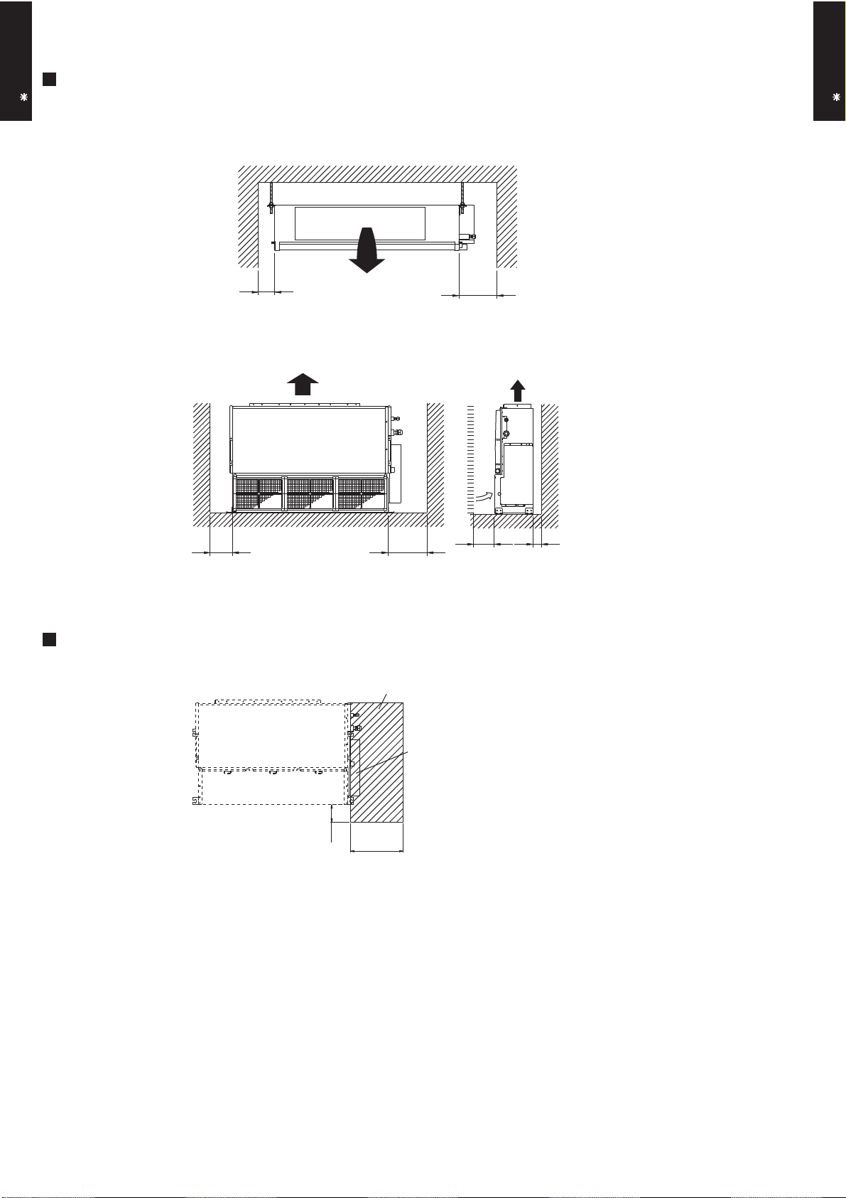
MAINTENANCE HOLE
Unit
100
Maintenance hole
300
or more
or more
(Unit : mm)
Control box
- (01 - 07) -
Page 9
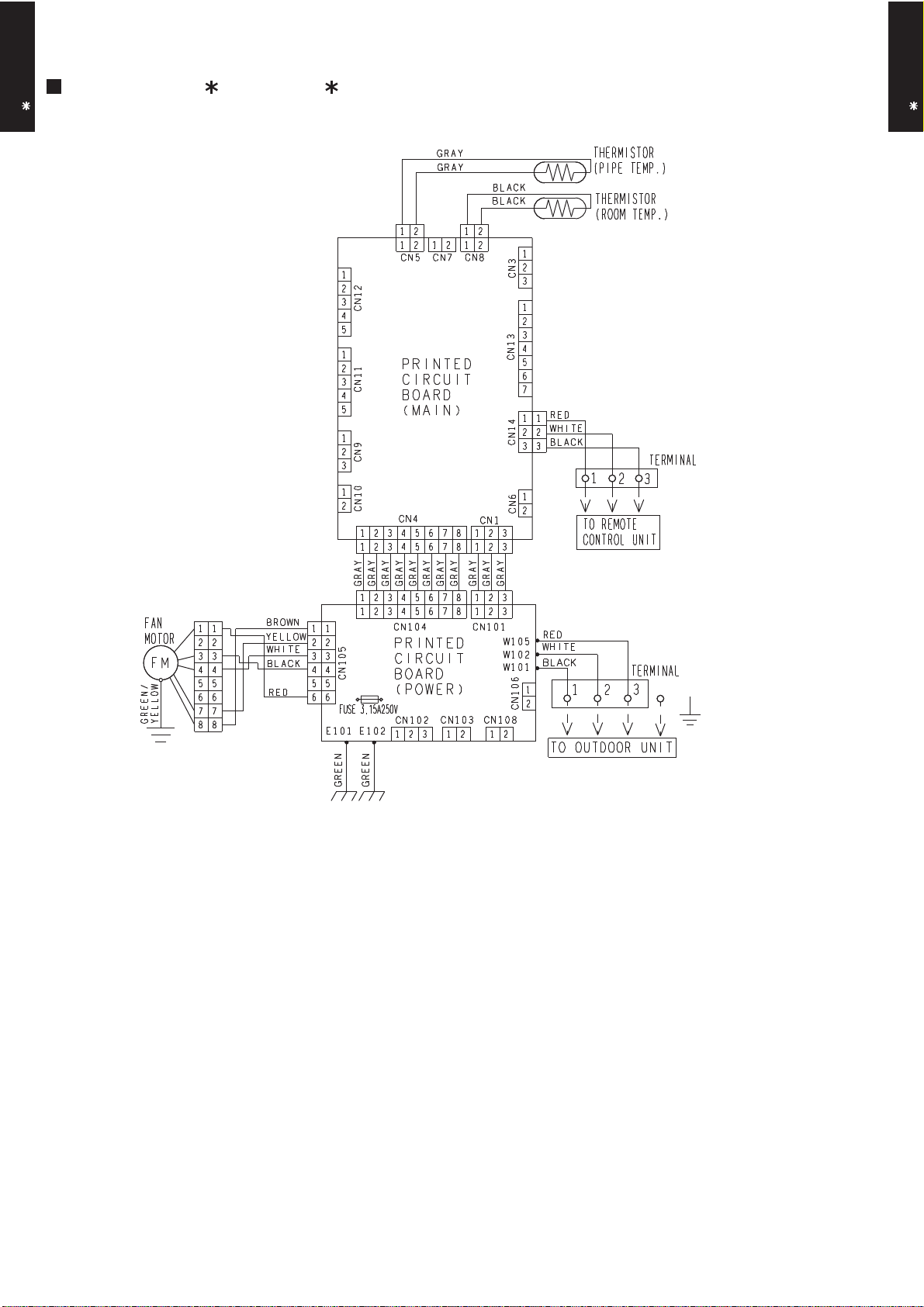
5. WIRING DIAGRAMS
MODEL : AR A18L, AR F18L
DUCT TYPE
AR A18L
DUCT TYPE
AR A18L
- (01 - 08) -
Page 10
6. CAPACITY TABLE
30
35
40
Outdoor temperature
°CDB
-10
0
5
10
15
20
46
25
2312151618
23
25
19
21
AFR
13.7
Indoor temperature
2729321821
AFR
13.7
46
25
30
35
40
Indoor temperature
Outdoor temperature
12
15
°CDB
-10
0
5
20
10
15
232518
21
16
18
272932
231921
6-1. COOLING CAPACITY
DUCT TYPE
AR A18L
This table is created using the maximum capacity.
MODEL : AR A18L, AR F18L / AO A18L
°CDB
°CWB
TC SHC PI TC SHC PI TC SHC PI TC SHC PI TC SHC PI TC SHC PI TC SHC PI
4.44 3.44 0.35 4.94 3.46 0.35 5.11 3.77 0.35 5.45 3.78 0.36 5.62 4.08 0.36 5.96 4.06 0.36 6.29 4.33 0.37
4.34 3.40 0.41 4.83 3.42 0.42 5.00 3.71 0.42 5.33 3.72 0.42 5.49 4.02 0.42 5.82 4.01 0.43 6.15 4.27 0.43
4.20 3.33 0.51 4.68 3.35 0.52 4.84 3.64 0.52 5.16 3.65 0.53 5.32 3.94 0.53 5.64 3.93 0.54 5.96 4.19 0.54
4.04 3.25 0.62 4.50 3.27 0.63 4.66 3.56 0.63 4.96 3.57 0.63 5.12 3.86 0.64 5.42 3.84 0.64 5.73 4.09 0.65
4.10 3.28 0.54 4.56 3.30 0.54 4.72 3.59 0.55 5.03 3.60 0.55 5.19 3.89 0.56 5.50 3.87 0.56 5.81 4.12 0.57
5.22 3.83 1.17 5.82 3.85 1.19 6.02 4.19 1.19 6.41 4.20 1.21 6.61 4.54 1.21 7.01 4.52 1.22 7.40 4.81 1.24
4.98 3.71 1.31 5.55 3.73 1.33 5.74 4.06 1.34 6.12 4.07 1.35 6.31 4.40 1.36 6.69 4.38 1.38 7.06 4.66 1.39
4.73 3.58 1.46 5.27 3.60 1.48 5.45 3.92 1.49 5.81 3.93 1.51 5.98 4.25 1.51 6.34 4.23 1.53 6.70 4.50 1.55
4.66 3.55 1.74 5.19 3.57 1.76 5.37 3.88 1.77 5.72 3.90 1.79 5.90 4.21 1.80 6.25 4.19 1.82 6.61 4.46 1.84
3.41 2.96 1.24 3.80 2.98 1.25 3.92 3.24 1.26 4.18 3.25 1.27 4.31 3.51 1.28 4.57 3.50 1.29 4.83 3.72 1.31
2.43 2.53 0.94 2.70 2.54 0.95 2.79 2.76 0.96 2.98 2.77 0.97 3.07 2.99 0.97 3.25 2.98 0.98 3.44 3.18 0.99
DUCT TYPE
AR A18L
MODEL : AR A18L, AR F18L / AO B18L
°CDB
°CWB
TC SHC PI TC SHC PI TC SHC PI TC SHC PI TC SHC PI TC SHC PI TC SHC PI
4.44 3.44 0.35 4.94 3.46 0.35 5.11 3.77 0.35 5.45 3.78 0.36 5.62 4.08 0.36 5.96 4.06 0.36 6.29 4.33 0.37
4.34 3.40 0.41 4.83 3.42 0.42 5.00 3.71 0.42 5.33 3.72 0.42 5.49 4.02 0.42 5.82 4.01 0.43 6.15 4.27 0.43
4.20 3.33 0.51 4.68 3.35 0.52 4.84 3.64 0.52 5.16 3.65 0.53 5.32 3.94 0.53 5.64 3.93 0.54 5.96 4.19 0.54
4.04 3.25 0.62 4.50 3.27 0.63 4.66 3.56 0.63 4.96 3.57 0.63 5.12 3.86 0.64 5.42 3.84 0.64 5.73 4.09 0.65
4.10 3.28 0.54 4.56 3.30 0.54 4.72 3.59 0.55 5.03 3.60 0.55 5.19 3.89 0.56 5.50 3.87 0.56 5.81 4.12 0.57
5.22 3.83 1.17 5.82 3.85 1.19 6.02 4.19 1.19 6.41 4.20 1.21 6.61 4.54 1.21 7.01 4.52 1.22 7.40 4.81 1.24
4.98 3.71 1.31 5.55 3.73 1.33 5.74 4.06 1.34 6.12 4.07 1.35 6.31 4.40 1.36 6.69 4.38 1.38 7.06 4.66 1.39
4.73 3.58 1.46 5.27 3.60 1.48 5.45 3.92 1.49 5.81 3.93 1.51 5.98 4.25 1.51 6.34 4.23 1.53 6.70 4.50 1.55
4.50 3.38 1.74 5.02 3.40 1.76 5.19 3.70 1.77 5.53 3.71 1.79 5.70 4.01 1.80 6.04 3.99 1.82 6.38 4.25 1.84
3.29 2.84 1.24 3.67 2.86 1.25 3.79 3.10 1.26 4.04 3.11 1.27 4.17 3.36 1.28 4.42 3.35 1.29 4.67 3.57 1.31
2.34 2.44 0.94 2.61 2.45 0.95 2.70 2.67 0.96 2.88 2.68 0.97 2.97 2.89 0.97 3.14 2.88 0.98 3.32 3.07 0.99
AFR: Air Flow Rate (m3/min)
TC : Total Capacity (kW)
SHC: Sensible Heat Capacity (kW)
PI : Power Input (kW)
- (01 - 09) -
Page 11
6-2. HEATING CAPACITY
24
18
Indoor temperature
20
15
15
10
10
8
7
6
-2
5
3
0
-15
-16
-10
-11
AFR
13.7
°CDB16182022
24
-5
Outdoor temperature
°CDB
°CWB
-7
Indoor temperature
AFR
°CDB
13.7
24
-16
-11
-7
18
20
7
3
-10
-5
Outdoor temperature
8510
15
10
6
0
-2
15
°CDB
°CWB
-15
2416182022
This table is created using the maximum capacity.
DUCT TYPE
AR A18L
MODEL : AR A18L, AR F18L / AO A18L
TC PI TC PI TC PI TC PI TC PI
5.06 2.18 4.94 2.22 4.81 2.27 4.69 2.31 4.57 2.36
5.71 2.29 5.58 2.33 5.44 2.38 5.30 2.43 5.17 2.48
6.37 2.41 6.22 2.46 6.06 2.51 5.91 2.56 5.76 2.61
7.25 2.58 7.08 2.63 6.91 2.68 6.73 2.74 6.56 2.79
8.13 2.75 7.93 2.81 7.74 2.87 7.55 2.93 7.35 2.98
7.87 2.36 7.69 2.41 7.50 2.46 7.31 2.51 7.12 2.56
8.16 2.41 7.97 2.46 7.77 2.51 7.58 2.57 7.39 2.62
7.75 2.07 7.56 2.11 7.38 2.16 7.19 2.20 7.01 2.24
7.24 1.65 7.07 1.68 6.90 1.72 6.73 1.75 6.55 1.79
7.46 1.65 7.29 1.69 7.11 1.72 6.93 1.76 6.75 1.79
DUCT TYPE
AR A18L
MODEL : AR A18L, AR F18L / AO B18L
TC PI TC PI TC PI TC PI TC PI
5.06 2.18 4.94 2.22 4.81 2.27 4.69 2.31 4.57 2.36
5.71 2.29 5.58 2.33 5.44 2.38 5.30 2.43 5.17 2.48
6.37 2.41 6.22 2.46 6.06 2.51 5.91 2.56 5.76 2.61
7.25 2.58 7.08 2.63 6.91 2.68 6.73 2.74 6.56 2.79
7.80 2.75 7.62 2.81 7.43 2.87 7.24 2.93 7.06 2.98
7.56 2.36 7.38 2.41 7.20 2.46 7.02 2.51 6.84 2.56
7.84 2.41 7.65 2.46 7.46 2.51 7.28 2.57 7.09 2.62
7.44 2.07 7.26 2.11 7.08 2.16 6.90 2.20 6.73 2.24
6.95 1.65 6.79 1.68 6.62 1.72 6.46 1.75 6.29 1.79
7.17 1.65 7.00 1.69 6.82 1.72 6.65 1.76 6.48 1.79
AFR : Air Flow Rate (m /min)
TC : Total Capacity (kW)
PI : Power Input (kW)
3
- (01 - 10) -
Page 12
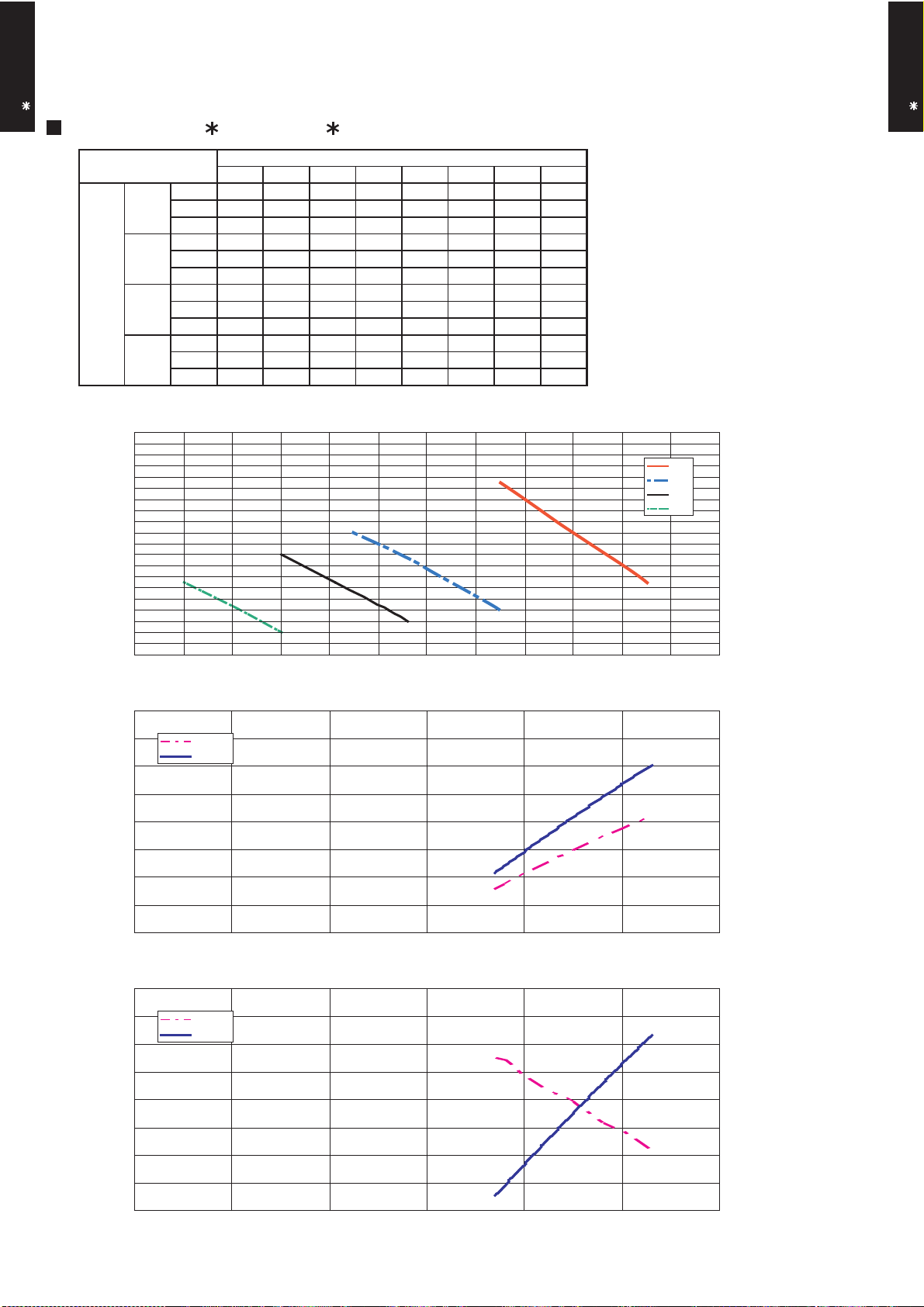
7. FAN PERFORMANCE AND CAPACITY
m3/h
850 830 820 810 801 793 784 775
m3/h
750 727 713 700 685 670 - -
m3/h
640 614 600 585 570 - - -
m3/h
540 504 483 460 - - - -
Static pressure (Pa)
Hi
Med
Quiet
Low
Hi
Med
Low
Quiet
7-1. NORMAL MODE
DUCT TYPE
AR A18L
MODEL : AR A18L, AR F18L
0 2 3 4 5 6 7 8
l/s 236 231 228 225 223 220 218 215
CFM 500 489 483 477 471 467 461 456
l/s 208 202 198 194 190 186 - -
CFM 441 428 420 412 403 394 - -
DUCT TYPE
AR A18L
FAN SPEED
l/s 178 171 167 163 158 - - -
CFM 377 361 353 344 335 - - -
l/s 150 140 134 128 - - - -
CFM 318 297 284 271 - - - -
Q-h Characteristic curve
20
15
10
5
0
400 500 600 700 800 900 1,000
102.0
100.0
AIR FLOW (m3/h)
Air temp
Capacity
COOLING
15.0
14.5
14.0
98.0
96.0
Cooling capacity(%) STATIC PRESSURE(Pa)Heating capacity(%)
94.0
400 500 600 700 800 900 1,000
AIR FLOW (m3/h)
102.0
Air temp
100.0
98.0
96.0
94.0
400 500 600 700 800 900 1,000
Capacity
AIR FLOW (m3/h)
- (01 - 11) -
HEATING
13.5
13.0
12.5
12.0
11.5
11.0
50.0
49.0
48.0
47.0
46.0
45.0
44.0
43.0
42.0
Air temperature(°C)Air temperature(°C)
Page 13
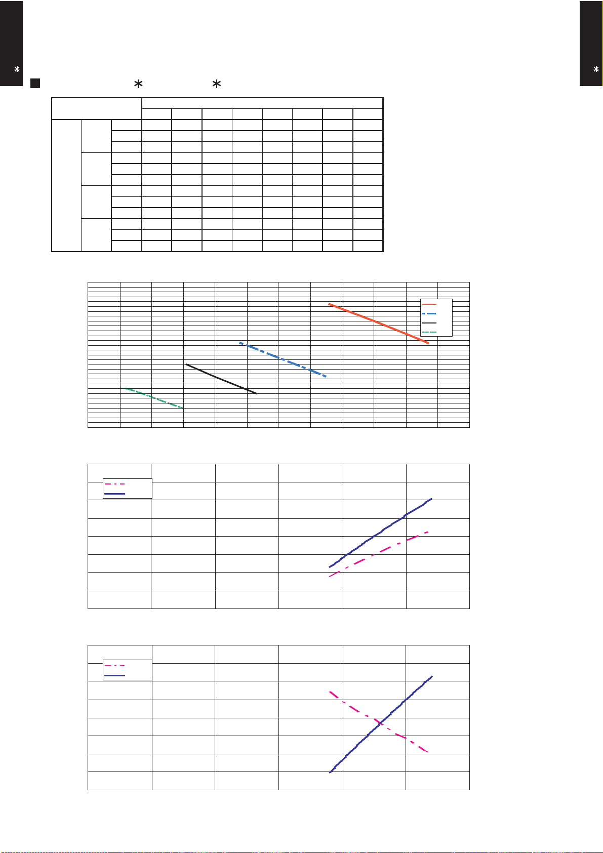
7-2. HIGH STATIC MODE
Hi
Med
Low
Quiet
m3/h
- - - 925 884 850 825 775
m3/h
- - 775 725 672 625 - -
m3/h
- 680 660 605 550 - - -
m3/h
550 530 508 450 - - - -
Med
Hi
FAN SPEED
Low
Static pressure (Pa)
Quiet
7-2-1. MODE 1
DUCT TYPE
AR A18L
MODEL : AR A18L, AR F18L
4 6 8 13 18 22 25 31
l/s - - - 257 246 236 229 215
CFM - - - 544 520 500 486 456
l/s - - 215 201 187 174 - -
CFM - - 456 427 396 368 - -
l/s - 189 183 168 153 - - -
CFM - 400 388 356 324 - - -
l/s 153 147 141 125 - - - -
CFM 324 312 299 265 - - - -
40
30
Q-h Characteristic curve
DUCT TYPE
AR A18L
20
10
0
400 500 600 700 800 900 1,000
AIR FLOW (m3/h)
102.0
Air temp
100.0
98.0
96.0
Cooling capacity(%) STATIC PRESSURE(Pa)Heating capacity(%)
94.0
400 500 600 700 800 900 1,000
Capacity
AIR FLOW (m3/h)
102.0
COOLING
HEATING
15.0
14.5
14.0
13.5
13.0
12.5
12.0
11.5
11.0
50.0
Air temperature(°C)Air temperature(°C)
Air temp
100.0
98.0
96.0
94.0
400 500 600 700 800 900 1,000
Capacity
AIR FLOW (m3/h)
- (01 - 12) -
49.0
48.0
47.0
46.0
45.0
44.0
43.0
42.0
Page 14
7-2-2. MODE 2
Hi
Med
Low
Quiet
m3/h
- - - - - 935 860 780
m3/h
- - - 775 727 640 - -
m3/h
- 665 645 600 555 - - -
m3/h
550 485 460 - - - - -
Low
Static pressure (Pa)
FAN SPEED
Hi
Med
Quiet
DUCT TYPE
AR A18L
MODEL : AR A18L, AR F18L
70
60
50
40
18 24 26 31 36 45 53 61
l/s - - - - - 260 239 217
CFM - - - - - 550 506 459
l/s - - - 215 202 178 - -
CFM - - - 456 428 377 - -
l/s - 185 179 167 154 - - -
CFM - 391 380 353 327 - - -
l/s 153 135 128 - - - - -
CFM 324 285 271 - - - - -
Q-h Characteristic curve
DUCT TYPE
AR A18L
30
20
10
400 500 600 700 800 900 1,000
AIR FLOW (m3/h)
102.0
Air temp
100.0
98.0
96.0
Cooling capacity(%) STATIC PRESSURE(Pa)Heating capacity(%)
94.0
400 500 600 700 800 900 1,000
Capacity
AIR FLOW (m3/h)
102.0
Air temp
100.0
Capacity
COOLING
HEATING
15.0
14.5
14.0
13.5
13.0
12.5
12.0
11.5
11.0
50.0
49.0
48.0
Air temperature(°C)Air temperature(°C)
98.0
96.0
94.0
400 500 600 700 800 900 1,000
AIR FLOW (m3/h)
- (01 - 13) -
47.0
46.0
45.0
44.0
43.0
42.0
Page 15

7-2-3. MODE 3
Hi
Med
Low
Quiet
m3/h
- - - - - - 925 800
m3/h
- - - - 740 650 - -
m3/h
- - 640 560 - - - -
m3/h
525 475 - - - - - -
Static pressure (Pa)
Quiet
Med
Hi
FAN SPEED
Low
DUCT TYPE
AR A18L
MODEL : AR A18L, AR F18L
90
80
70
60
34 38 46 52 57 65 76 90
l/s - - - - - - 257 222
CFM - - - - - - 544 471
l/s - - - - 206 181 - -
CFM - - - - 436 383 - -
l/s - - 178 156 - - - -
CFM - - 377 330 - - - -
l/s 146 132 - - - - - -
CFM 309 280 - - - - - -
Q-h Characteristic curve
DUCT TYPE
AR A18L
50
40
30
400 500 600 700 800 900 1,000
AIR FLOW (m3/h)
102.0
Air temp
100.0
98.0
96.0
Cooling capacity(%) STATIC PRESSURE(Pa)Heating capacity(%)
94.0
400 500 600 700 800 900 1,000
Capacity
AIR FLOW (m3/h)
102.0
Air temp
100.0
Capacity
COOLING
HEATING
15.0
14.5
14.0
13.5
13.0
12.5
12.0
11.5
11.0
50.0
49.0
48.0
Air temperature(°C)Air temperature(°C)
98.0
96.0
94.0
400 500 600 700 800 900 1,000
AIR FLOW (m3/h)
- (01 - 14) -
47.0
46.0
45.0
44.0
43.0
42.0
Page 16

8. OPERATION NOISE
HIGH
QUIET
HIGH
8-1. NOISE LEVEL CURVE
DUCT TYPE
AR A18L
MODEL : AR A18L, AR F18L
COOLING HEATING
80
Condition
Static pressure : 0Pa
Static mode : Normal
DUCT TYPE
AR A18L
80
70
60
50
40
30
QUIET
20
Octave band sound pressure level, dB:(0dB=0.0002µbar)
10
0
63 125 250 500 1,000 2,000 4,000 8,000
Octave band center frequency,Hz
NC-65
NC-60
NC-55
NC-50
NC-45
NC-40
NC-35
NC-30
NC-25
NC-20
NC-15
70
60
50
40
30
20
Octave band sound pressure level, dB:(0dB=0.0002µbar)
10
0
63 125 250 500 1,000 2,000 4,000 8,000
Octave band center frequency,Hz
NC-65
NC-60
NC-55
NC-50
NC-45
NC-40
NC-35
NC-30
NC-25
NC-20
NC-15
- (01 - 15) -
Page 17

8-2. SOUND LEVEL CHECK POINT
DUCT TYPE
AR A18L
Microphone Microphone
DUCT TYPE
AR A18L
- (01 - 16) -
Page 18

9. ELECTRIC CHARACTERISTICS
DUCT TYPE
AR A18L
Model Name
AR A18L, AR F18L
DUCT TYPE
AR A18L
Power Supply
Voltage V 230
Frequency Hz 50
Max Operating Current A 0.5
*1)Wiring Spec.
Connection Cable
mm
2
1.5 - 2.5
Limited wiring length m 26
*1) Wiring Spec.
Selected Sample
(Selected based on Japan Electrotechnical Standard and Codes Committee E0005)
- (01 - 17) -
Page 19

10. SAFETY DEVICES
DUCT TYPE
AR A18L
Circuit protection Current fuse (PCB) 3.15A 250V
Protection form
Model
AR A18L, AR F18L
DUCT TYPE
AR A18L
Fan motor protection Thermal protection program
140±20°C OFF
110±20°C ON
- (01 - 18) -
Page 20

11. OPTIONAL PARTS
DUCT TYPE
AR A18L
Exterior Summary
Parts name
Remote Sensor
Model No.
UTD-RS100
New amenity space can be
offered by installing the
Remote sensor in the remote
controller.
DUCT TYPE
AR A18L
External
control set
IR Receiver
unit
Drain pump
unit
UTD-ECS5A
UTY-LRH 1
UTZ-PX1BBA
Use to connect with various
peripheral devices and air
conditioner PC board.
Unit control is performed by
wireless remote controller.
Optional drain lift up
mechanism allows more
flexible installation.
- (01 - 19) -
Page 21

R410A
OUTDOOR UNIT
2.
SINGLE TYPE :
AO A18LACL
AO A18LALL
AO A24LACL
AO A24LALL
D2D_AO004E/04
2008.04.08
Page 22

1. SPECIFICATIONS
OUTDOOR UNIT
AO A18-24L
Type
Model name
Power source
Available voltage range
Starting current
Airflow
Fan
Sound pressure level
Heat exchanger type
Compressor
Refrigerant
Refrigerant oil
Enclosure
Dimensions
( H × W × D)
Weight kg(lb.)
Connection pipe
rate
Type × Q'ty
Motor output
Type × Q'ty
Motor output
Net
Gross
Net
Gross
Size mm
Method
Max. length
Max. height difference
Cooling
Heating
Cooling
Heating
Dimensions (H × W × D)
Fin pitch
Rows x Stages
Pipe type
Fin type
Type
Charge
Type
Material
Colour
Liquid
Gas
Cooling
Heating
A 7.7 10.0
m3/h
W 54 65
dB(A)
mm
W
g 1250 1700
mm
m
°COperation range
INVERTER HEATPUMP
AO A18LACL AO A24LACL
AO A18LALL AO A24LALL
230V 50Hz
198-264V 50Hz
2000 2470
1910 2470
Propeller × 1
50 52
50 53
546 × 876 × 18.2
546 × 842 × 18.2
1.30 1.40
2 × 26
Copper
Aluminium
Twin Rotary × 1
1100
R410A
POE
Steel sheet
Beige (10YR7.5/1.0NN)
578 × 790 × 300 578 × 790 × 315
648 × 910 × 380
40 (88) 44 (97)
44 (97) 48 (106)
Φ
6.35 (Φ 1/4 in.)
Φ
12.70 (Φ 1/2 in.)
Flare
25(chargeless : 15) 30(chargeless : 15)
15 20
-10 to 46
-15 to 24
546 × 866 × 18.2
546 × 832 × 18.2
504 × 589 × 18.2
2 × 26
1 × 24
Φ
15.88(Φ 5/8 in.)
OUTDOOR UNIT
AO A18-24L
Note :
Specifications are based on the following conditions.
Cooling : Indoor temperature of 27°CDB/19°CWB. and outdoor temperature of 35°CDB/24°CWB.
Heating : Indoor temperature of 20°CDB/15°CWB. and outdoor temperature of 7°CDB/6°CWB.
Pipe length : 7.5 m, Height difference : 0 m. (Outdoor unit - Indoor unit)
- (02 - 01) -
Page 23

2. DIMENSIONS
MODELS : AO A18L, AO A24L
OUTDOOR UNIT
AO A18-24L
Top view
(Unit : mm)
OUTDOOR UNIT
AO A18-24L
Front view
Bottom view
MOUNTING POSITION
When there are obstacles at the
back or front sides.
Air flow
When there are obstacles at the
back, side(s), and top.
AO A18L AO A24L
Side view
When there are obstacles at the
back, side with the installation of
more than one unit.
600 - 1000
100 or more
600 or more
100 - 300
250 or more
(Service space)
300 or more
250 or more
250 or more
If the space is larger that is stated, the condition will be the same as that are no obstacles.
- (02 - 02) -
300 or more
Page 24

3. REFRIGERANT CIRCUIT
OUTDOOR UNIT
AO A18-24L
OUTDOOR UNIT
AO A18-24L
- (02 - 03) -
Page 25

4. WIRING DIAGRAMS
MODELS : AO A18L, AO A24L
OUTDOOR UNIT
AO A18-24L
OUTDOOR UNIT
AO A18-24L
- (02 - 04) -
Page 26

5. CAPACITY COMPENSATION RATE FOR PIPE LENGTH
AND HEIGHT DIFFERENCE
MODEL : AO A18L
OUTDOOR UNIT
AO A18-24L
Height
difference H
(m)
Height
difference H
(m)
COOLING
1
Indoor unit is upper
than outdoor unit.
2
Indoor unit is under
than outdoor unit
HEATING
1
Indoor unit is upper
than outdoor unit.
2
Indoor unit is under
than outdoor unit
Pipe length (m)
5 7.5 10 15 20 25
15 - - -
10 - -
7.5 -
5
0 1.000 1.000 0.999 0.984 0.982 0.978
-5
-7.5 -
-10 - -
-15 - - -
15 - - -
10 - -
7.5 -
5
0 0.993 1.000 0.982 0.920 0.894 0.867
-5
-7.5 -
-10 - -
-15 - - -
0.992 0.992 0.991 0.976 0.974 0.970
1.000 1.000 0.999 0.984 0.982 0.978
5 7.5 10 15 20 25
0.993 1.000 0.982 0.920 0.894 0.867
0.988 0.995 0.977 0.916 0.889 0.862
0.988 0.987 0.972 0.970 0.966
1.000 0.999 0.984 0.982 0.978
1.000 0.982 0.920 0.894 0.867
0.993 0.975 0.913 0.887 0.860
0.983 0.968 0.966 0.962
0.999 0.984 0.982 0.978
Pipe length (m)
0.982 0.920 0.894 0.867
0.972 0.911 0.885 0.858
0.953 0.950 0.947
0.984 0.982 0.978
0.920 0.894 0.867
0.902 0.876 0.849
OUTDOOR UNIT
AO A18-24L
Indoor unit
H
Outdoor unit
Connection pipe
1
Indoor unit is upper than outdoor unit.
Height difference H
Outdoor unit
Connection pipe
2
Indoor unit is under than outdoor unit.
- (02 - 05) -
H
Indoor unit
Page 27

MODEL : AO A24L
OUTDOOR UNIT
AO A18-24L
Height
difference H
(m)
Height
difference H
(m)
COOLING
1
Indoor unit is upper
than outdoor unit.
2
Indoor unit is under
than outdoor unit
HEATING
1
Indoor unit is upper
than outdoor unit.
2
Indoor unit is under
than outdoor unit
Pipe length (m)
5 7.5 10 15 20 25 30
20
10
7.5
5
0
-5
-7.5
-10
-20
- - - - 0.963 0.961 0.959
- - 0.984 0.981 0.979 0.977 0.975
- 0.988 0.988 0.985 0.983 0.981 0.979
0.992 0.992 0.992 0.989 0.987 0.985 0.983
1.000 1.000 1.000 0.997 0.995 0.993 0.991
1.000 1.000 1.000 0.997 0.995 0.993 0.991
- 1.000 1.000 0.997 0.995 0.993 0.991
- - 1.000 0.997 0.995 0.993 0.991
- - - - 0.995 0.993 0.991
Pipe length (m)
5 7.5 10 15 20 25 30
20 - - - -
10 - -
7.5 -
5
1.001 1.000 0.992 0.952 0.927 0.893 0.863
1.000 0.992 0.952 0.927 0.893 0.863
0.992 0.952 0.927 0.893 0.863
0.927 0.893 0.863
0 1.001 1.000 0.992 0.952 0.927 0.893 0.863
-5
-7.5 -
-10 - -
-20 - - - -
0.996 0.995 0.987 0.947 0.922 0.888 0.859
0.993 0.984 0.945 0.920 0.886 0.857
0.982 0.943 0.917 0.884 0.855
0.908 0.875 0.846
OUTDOOR UNIT
AO A18-24L
Indoor unit
H
Outdoor unit
Connection pipe
1
Indoor unit is upper than outdoor unit.
Height difference H
Outdoor unit
Connection pipe
2
Indoor unit is under than outdoor unit.
- (02 - 06) -
H
Indoor unit
Page 28

6. ADDITIONAL CHARGE CALCULATION
20g/m
1700
R410A
1250
20g/m
R410A
MODEL : AO A18L
Refrigerant type
Refrigerant amount g
OUTDOOR UNIT
AO A18-24L
REFRIGERANT CHARGE
Pipe length m 15 20 25
Additional charge g 0 (Chargeless) +100 +200
MODEL : AO A24L
Refrigerant type
Refrigerant amount g
REFRIGERANT CHARGE
Pipe length m 15 20 25 30
Additional charge g 0 (Chargeless) +100 +200 +300
OUTDOOR UNIT
AO A18-24L
- (02 - 07) -
Page 29

7. AIR FLOW
m3/h
2000
m3/h
1910
m3/h
2470
m3/h
2470
1050
NUMBER OF
ROTATIONS
(r.p.m)
NUMBER OF
ROTATIONS
(r.p.m)
NUMBER OF
ROTATIONS
(r.p.m)
NUMBER OF
ROTATIONS
(r.p.m)
860
820
1050
Airflow
Airflow
Airflow
Airflow
MODEL : AO A18L
COOLING
OUTDOOR UNIT
AO A18-24L
HEATING
l/s 556
CFM 1177
OUTDOOR UNIT
AO A18-24L
l/s 531
CFM 1124
MODEL : AO A24L
COOLING
l/s 686
CFM 1454
HEATING
l/s 686
CFM 1454
- (02 - 08) -
Page 30

8. OPERATION NOISE
8-1. NOISE LEVEL CURVE
COOLING
OUTDOOR UNIT
AO A18-24L
MODEL : AO A18L
80
70
60
50
40
30
20
Octave band sound pressure level, dB:(0dB=0.0002µbar)
10
0
63 125 250 500 1,000 2,000 4,000 8,000
Octave band center frequency,Hz
NC-65
NC-60
NC-55
NC-50
NC-45
NC-40
NC-35
NC-30
NC-25
NC-20
NC-15
MODEL : AO A24L
80
70
60
50
40
30
20
Octave band sound pressure level, dB:(0dB=0.0002µbar)
10
0
63 125 250 500 1,000 2,000 4,000 8,000
Octave band center frequency,Hz
NC-65
NC-60
NC-55
NC-50
NC-45
NC-40
NC-35
NC-30
NC-25
NC-20
NC-15
OUTDOOR UNIT
AO A18-24L
HEATING
MODEL : AO A18L
80
70
60
50
40
30
20
Octave band sound pressure level, dB:(0dB=0.0002µbar)
10
NC-65
NC-60
NC-55
NC-50
NC-45
NC-40
NC-35
NC-30
NC-25
NC-20
NC-15
MODEL : AO A24L
80
70
60
50
40
30
20
Octave band sound pressure level, dB:(0dB=0.0002µbar)
10
NC-65
NC-60
NC-55
NC-50
NC-45
NC-40
NC-35
NC-30
NC-25
NC-20
NC-15
0
63 125 250 500 1,000 2,000 4,000 8,000
Octave band center frequency,Hz
- (02 - 09) -
0
63 125 250 500 1,000 2,000 4,000 8,000
Octave band center frequency,Hz
Page 31

8-2. SOUND LEVEL CHECK POINT
OUTDOOR UNIT
AO A18-24L
OUTDOOR UNIT
AO A18-24L
- (02 - 10) -
Page 32

9. ELECTRIC CHARACTERISTICS
Model Name AO A18L AO A24L
OUTDOOR UNIT
AO A18-24L
Voltage V
230
Power Supply
Frequency Hz
50
Max Operating Current A 15.0 16.2
Starting Current A 7.7 10.0
*1) Wiring Spec.
Main Fuse (Circuit breaker)
Current
Power Cable
A 20 20
mm
2
3.5 - 4.5
*2)Limited wiring length m 24 22
*1) Wiring Spec.
Selected Sample
(Selected based on Japan Electrotechnical Standard and Codes Committee E0005)
*2) Limited Wiring length :
This is the wiring length in case voltage descent is less than 2%.
When the wiring length becomes long, please select the wiring of a more larger diameter.
OUTDOOR UNIT
AO A18-24L
- (02 - 11) -
Page 33

10. SAFETY DEVICES
AO A18L AO A24L
OFF:100
+15
-10
°C
ON:95
+15
-10
°C
OFF:110
+15
-10
°C
ON:105
+15
-10
°C
15A 250V
3.15A 250V
Compressor protection
Circuit protection
OFF:110°C
ON: After 40 minutes
OFF:110°C
ON: After 7 minutes
Current fuse (NEAR THE TERMINAL)
Current fuse
(MAIN PRINTED CIRCUIT BOARD)
Protection form
20A 250V
5A 250V
Model
OUTDOOR UNIT
AO A18-24L
Fan motor protection Thermal protection program
Thermal protection program
(COMPRESSOR TEMP.)
Thermal protection program
(DISCHARGE TEMP.)
OUTDOOR UNIT
AO A18-24L
- (02 - 12) -
Page 34

R410A
D2D_AO021E/02
2008.04.08
2.
SINGLE TYPE :
AO B18LACL
AO B18LALL
OUTDOOR UNIT
AO B24LACL
AO B24LALL
Page 35

- (02 - 01) -
OUTDOOR UNIT
AOB18-24L
OUTDOOR UNIT
AOB18-24L
1. SPECIFICATIONS
Note :
Specifications are based on the following conditions.
Cooling : Indoor temperature of 27°CDB/19°CWB. and outdoor temperature of 35°CDB/24°CWB.
Heating : Indoor temperature of 20°CDB/15°CWB. and outdoor temperature of 7°CDB/6°CWB.
Pipe length : 7.5 m, Height difference : 0 m. (Outdoor unit - Indoor unit)
Power source
Available voltage range
A 7.7 10.0
Cooling 2000 2470
Heating 1910 2470
Type × Q'ty
Motor output W 54 65
Cooling 50 52
Heating 50 53
Dimensions (H × W × D)
546 × 876 × 18.2
546 × 842 × 18.2
546 × 866 × 18.2
546 × 832 × 18.2
504 × 589 × 18.2
Fin pitch 1.30 1.40
Rows x Stages 2 × 26
2 × 26
1 × 24
Pipe type
Fin type
Motor output W
Charge g 1250 1700
Material
Colour
Net 578 × 790 × 300 578 × 790 × 315
Gross
Net 40 ( 88 ) 44 ( 97 )
Gross 44 ( 97 ) 48 ( 106 )
Liquid
Gas
Φ 12.70 (Φ 1/2 in.) Φ 15.88 (Φ 5/8 in.)
Method
Max. length 25(chargeless:15) 30(chargeless:15)
Max. height difference 15 20
Cooling
Heating
Flare
-10 to 46
-15 to 24
648 × 910 × 380
Φ 6.35 (Φ 1/4 in.)
Copper
Aluminium
Steel sheet
Beige (10YR7.5/1.0NN)
Twin Rotary × 1
1100
R410A
POE
INVERTER HEATPUMP
230V ~50Hz
198-264V ~50Hz
Propeller × 1
m
Connection pipe
Size mm
Starting current
Compressor
Type × Q'ty
Refrigerant
Type
Sound pressure level
Refrigerant oil Type
Enclosure
Heat exchanger type
mm
Weight kg(lb.)
Dimensions
( H×W×D)
°COperation range
Type
Model name
Fan
Airflow
rate
m3/h
dB(A)
mm
AO B18LACL AO B24LACL
AO B18LALL AO B24LALL
Page 36

- (02 - 02) -
OUTDOOR UNIT
AOB18-24L
OUTDOOR UNIT
AOB18-24L
2. DIMENSIONS
MODEL : AO B18L, AO B24L
(Unit : mm)
(Unit : mm)
Air flow
Top view
When there are obstacles at the
back or front sides.
When there are obstacles at the
back, side(s), and top.
When there are obstacles at the
back, side with the installation of
more than one unit.
600 or more
250 or more
250 or more
300 or more
600 - 1000
100 or more
300 or more
100 - 300
250 or more
(Service space)
MOUNTING POSITION
Front view
AO B18L AO B24L
Side view
Bottom view
If the space is larger that is stated, the condition will be the same as that are no obstacles.
Page 37

- (02 - 03) -
OUTDOOR UNIT
AOB18-24L
OUTDOOR UNIT
AOB18-24L
3. REFRIGERANT CIRCUIT
Page 38

- (02 - 04) -
OUTDOOR UNIT
AOB18-24L
OUTDOOR UNIT
AOB18-24L
MODEL : AO B18L, AO B24L
4. WIRING DIAGRAMS
Page 39

- (02 - 05) -
OUTDOOR UNIT
AOB18-24L
OUTDOOR UNIT
AOB18-24L
5. CAPACITY COMPENSATION RATE FOR PIPE LENGTH
AND HEIGHT DIFFERENCE
MODEL : AO B18L
Indoor unit
Height difference H
Connection pipe
H
Outdoor unit
Indoor unit
Connection pipe
H
Outdoor unit
Indoor unit is upper than outdoor unit.
1
Indoor unit is under than outdoor unit.
2
5 7.5 10 15 20 25
15 - - -
0.984 0.982 0.978
10 - -
0.999 0.984 0.982 0.978
7.5 -
1.000 0.999 0.984 0.982 0.978
5
1.000 1.000 0.999 0.984 0.982 0.978
0 1.000 1.000 0.999 0.984 0.982 0.978
-5
0.992 0.992 0.991 0.976 0.974 0.970
-7.5 -
0.988 0.987 0.972 0.970 0.966
-10 - -
0.983 0.968 0.966 0.962
-15 - - -
0.953 0.950 0.947
5 7.5 10 15 20 25
15 - - -
0.902 0.876 0.849
10 - -
0.972 0.911 0.885 0.858
7.5 -
0.993 0.975 0.913 0.887 0.860
5
0.988 0.995 0.977 0.916 0.889 0.862
0 0.993 1.000 0.982 0.920 0.894 0.867
-5
0.993 1.000 0.982 0.920 0.894 0.867
-7.5 -
1.000 0.982 0.920 0.894 0.867
-10 - -
0.982 0.920 0.894 0.867
-15 - - -
0.920 0.894 0.867
Height
difference H
(m)
1
Indoor unit is upper
than outdoor unit.
2
Indoor unit is under
than outdoor unit
Pipe length (m)
Pipe length (m)
HEATING
COOLING
1
Indoor unit is upper
than outdoor unit.
2
Indoor unit is under
than outdoor unit
Height
difference H
(m)
Page 40

- (02 - 06) -
OUTDOOR UNIT
AOB18-24L
OUTDOOR UNIT
AOB18-24L
MODEL : AO B24L
Indoor unit
Height difference H
Connection pipe
H
Outdoor unit
Indoor unit
Connection pipe
H
Outdoor unit
Indoor unit is upper than outdoor unit.
1
Indoor unit is under than outdoor unit.
2
5 7.5 10 15 20 25 30
20
10
7.5
5
0
-5
-7.5
-10
-20
5 7.5 10 15 20 25 30
20 - - - -
0.908 0.875 0.846
10 - -
0.982 0.943 0.917 0.884 0.855
7.5 -
0.993 0.984 0.945 0.920 0.886 0.857
5
0.996 0.995 0.987 0.947 0.922 0.888 0.859
0 1.001 1.000 0.992 0.952 0.927 0.893 0.863
-5
1.001 1.000 0.992 0.952 0.927 0.893 0.863
-7.5 -
1.000 0.992 0.952 0.927 0.893 0.863
-10 - -
0.992 0.952 0.927 0.893 0.863
-20 - - - -
0.927 0.893 0.863
HEATING
COOLING
1
Indoor unit is upper
than outdoor unit.
2
Indoor unit is under
than outdoor unit
Height
difference H
(m)
Pipe length (m)
Pipe length (m)
Height
difference H
(m)
1
Indoor unit is upper
than outdoor unit.
2
Indoor unit is under
than outdoor unit
- - - - 0.963 0.961 0.959
- - 0.984 0.981 0.979 0.977 0.975
- 0.988 0.988 0.985 0.983 0.981 0.979
0.992 0.992 0.992 0.989 0.987 0.985 0.983
1.000 1.000 1.000 0.997 0.995 0.993 0.991
1.000 1.000 1.000 0.997 0.995 0.993 0.991
- 1.000 1.000 0.997 0.995 0.993 0.991
- - 1.000 0.997 0.995 0.993 0.991
- - - - 0.995 0.993 0.991
Page 41

- (02 - 07) -
OUTDOOR UNIT
AOB18-24L
OUTDOOR UNIT
AOB18-24L
6. ADDITIONAL CHARGE CALCULATION
MODEL : AO B18L
REFRIGERANT CHARGE
MODEL : AO B24L
REFRIGERANT CHARGE
Refrigerant type
Refrigerant amount g
Pipe length m 15 20 25
Additional charge g 0 (Chargeless) +100 +200
Refrigerant type
Refrigerant amount g
Pipe length m 15 20 25 30
Additional charge g 0 (Chargeless) +100 +200 +300
20g/m
1700
R410A
1250
20g/m
R410A
Page 42

- (02 - 08) -
OUTDOOR UNIT
AOB18-24L
OUTDOOR UNIT
AOB18-24L
MODEL : AO B18L
7. AIR FLOW
COOLING
HEATING
MODEL : AO B24L
COOLING
HEATING
m3/h
2000
l/s 556
CFM 1177
m3/h
1910
l/s 531
CFM 1124
m3/h
2470
l/s 686
CFM 1454
m3/h
2470
l/s 686
CFM 1454
1050
NUMBER OF
ROTATIONS
(r.p.m)
NUMBER OF
ROTATIONS
(r.p.m)
NUMBER OF
ROTATIONS
(r.p.m)
NUMBER OF
ROTATIONS
(r.p.m)
860
820
1050
Airflow
Airflow
Airflow
Airflow
Page 43

- (02 - 09) -
OUTDOOR UNIT
AOB18-24L
OUTDOOR UNIT
AOB18-24L
8-1. NOISE LEVEL CURVE
COOLING
HEATING
8. OPERATION NOISE
MODEL : AO B18L
COOLING HEATING
MODEL : AO B24L
Octave band sound pressure level, dB:(0dB=0.0002µbar)
Octave band center frequency,Hz
0
10
20
30
40
50
60
70
80
63 125 250 500 1,000 2,000 4,000 8,000
NC-20
NC-40
NC-50
NC-60
NC-30
NC-15
NC-25
NC-35
NC-45
NC-55
NC-65
Octave band sound pressure level, dB:(0dB=0.0002µbar)
Octave band center frequency,Hz
0
10
20
30
40
50
60
70
80
63 125 250 500 1,000 2,000 4,000 8,000
NC-20
NC-40
NC-50
NC-60
NC-30
NC-15
NC-25
NC-35
NC-45
NC-55
NC-65
Octave band sound pressure level, dB:(0dB=0.0002µbar)
Octave band center frequency,Hz
0
10
20
30
40
50
60
70
80
63 125 250 500 1,000 2,000 4,000 8,000
NC-20
NC-40
NC-50
NC-60
NC-30
NC-15
NC-25
NC-35
NC-45
NC-55
NC-65
Octave band sound pressure level, dB:(0dB=0.0002µbar)
Octave band center frequency,Hz
0
10
20
30
40
50
60
70
80
63 125 250 500 1,000 2,000 4,000 8,000
NC-20
NC-40
NC-50
NC-60
NC-30
NC-15
NC-25
NC-35
NC-45
NC-55
NC-65
Page 44

- (02 - 10) -
OUTDOOR UNIT
AOB18-24L
OUTDOOR UNIT
AOB18-24L
8-2. SOUND LEVEL CHECK POINT
Page 45

- (02 - 11) -
OUTDOOR UNIT
AOB18-24L
OUTDOOR UNIT
AOB18-24L
9. ELECTRIC CHARACTERISTICS
*1) Wiring spec.
Selected sample
(Selected based on Japan Electrotechnical Standard and Codes Committee E0005)
*2) Limited wiring length :
This is the wiring length in case voltage descent is less than 2%.
When the wiring length becomes long, please select the wiring of a more larger diameter.
Model name AO B18L AO B24L
Voltage V
Frequency Hz
Max. operating current A 15.0 16.2
Starting current A 7.7 10.0
Main fuse (Circuit breaker)
current
A 20 20
Power cable
mm
2
*2)Limited wiring length m 24 22
Power supply
*1) Wiring spec.
230
~
50
4.0
Page 46

- (02 - 12) -
OUTDOOR UNIT
AOB18-24L
OUTDOOR UNIT
AOB18-24L
10. SAFETY DEVICES
AO B18L AO B24L
Fan motor protection Thermal protection program
OFF:100
+15
-10
°C
ON:95
+15
-10
°C
OFF:110
+15
-10
°C
ON:105
+15
-10
°C
Thermal protection program
(COMPRESSOR TEMP.)
Thermal protection program
(DISCHARGE TEMP.)
15A 250V
3.15A 250V
Compressor protection
Circuit protection
OFF:110°C
ON: After 40 minutes
OFF:110°C
ON: After 7 minutes
Current fuse (NEAR THE TERMINAL)
Current fuse
(MAIN PRINTED CIRCUIT BOARD)
Protection form
20A 250V
5A 250V
Model
 Loading...