

Page 1
INVERTER SPLIT TYPE
AIR CONDITIONER (50Hz)
DUCT type
Models
Indoor unit Outdoor unit
ARH12LUAD AOH12LMAKL
ARH14LUAD AOH14LMAKL
CONTENTS
SPECIFICATIONS
OUTLINE AND DIMENSIONS
REFRIGERANT SYSTEM DIAGRAM
CIRCUIT DIAGRAM
INDOOR PCB CIRCUIT DIAGRAM
ERROR CONTENTS
DISASSEMBLY ILLUSTRATION
PARTS LIST
STANDARD ACCESSORIES
. . . . . . . . . . . . . . . . . . . . . . . . . . .
. . . . . . . . . . . . . . . .
. . . . . . . . . . . . . . . . . . . . . . . . .
. . . . . . . . . . . . . . . . . . . . . . . .
. . . . . . . . . . . . .
. . . . . . . . . . . . . . . . . . . . . . . . . . . . . . .
. . . . . . . . . . . . . . . .
. . . . . . . . .
. . . . . . . . . . .
. . . . . . . .
1
2
4
5
7
8OUTDOOR PCB CIRCUIT DIAGRAM
9
11
16
18
Page 2
SPECIFICATIONS
TYPE
INDOOR UNIT
OUTDOOR UNIT
COOLING CAPACITY
HEATING CAPACITY
AOH12LMAKL AOH14LMAKL
COOLING & HEATING
ARH12LUAD ARH14LUAD
3.50 kW 4.30 kW
4.00 kW 4.80 kW
ELECTRICAL DATA
POWER SOURCE
FREQUENCY
RUNNING CURRENT
INPUT WATTS
E.E.R.
MOISTURE REMOVAL
Note : The above list shows values at the external static pressure of 0Pa, setting the fan speed high notch.
COOLING
HEATING
COOLING
HEATING
COOLING
HEATING
5.10 A 6.00 A
5.80 A 6.50 A
1.15 kW 1.37 kW
1.32 kW 1.49 kW
3.04 kW/kW 3.14 kW/kW
3.03 kW/kW 3.21 kW/kW
1.2 l/hr 1.5 l/hr
230 V
50 Hz
COMPRESSOR
TYPE
Hermetic type, 4 poles, DC motor,
Twin Rotary
DISCRIMINATION
REFRIGERANT (R410A)
TNB220FPCM
1,250 g
FAN MOTOR
DISCRIMINATION
HIGH-SPEED
FAN SPEED
AIR FLOW
DIMENSIONS
WEIGHT
Note : The above list shows values at the external static pressure of 0Pa,setting the fan speed high notch.
INDOOR
DISCRIMINATION
OUTDOOR
H x W x D
GROSS / NET
MED-SPEED
LOW-SPEED
HIGH-SPEED
LOW-SPEED
INDOOR
OUTDOOR
INDOOR
OUTDOOR
INDOOR
OUTDOOR
MFA-18NTT MFA-18NTT
750 r.p.m. 1,000 r.p.m.
680 r.p.m. 860 r.p.m.
610 r.p.m. 720 r.p.m.
MFB-24JTAT
780 r.p.m.
400 r.p.m.
580 m3/h 780 m3/h
2,800 m3/h
217 x 953 x 595 mm
650 x 830 x 320 mm
29 / 25 kg
58 / 54 kg
NOISE LEVEL
HIGH-SPEED
INDOOR UNIT
OUTDOOR UNIT
Note : Static pressure : 0Pa / Duct length : Inlet 0.5m, Outlet 1m
MED-SPEED
LOW-SPEED
COOL
HEAT
32 dB 38 dB
29 dB 34 dB
27 dB 30 dB
50 dB 50 dB
52 dB 52 dB
REFRIGERANT
PIPE LENGTH
FULL CHARGE AMOUNT
ADDITIONAL REFRIGERANT
MAXIMUM PIPE HEIGHT
When you dismantle indoor units which are installed, take care not to make parts fall down, especially motors.
10 m
15 m
20 m
25 m
1,250 g
1,350 g
1,450 g
1,550 g
20 g / m
15 m
12006.05.25
Page 3
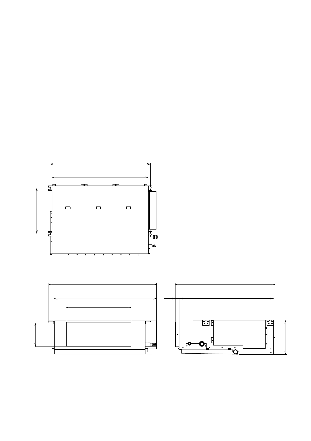
OUTLINE AND DIMENSIONS
INDOOR UNIT
(unit : mm)
Models :
ARH12LUAD
ARH14LUAD
886
850
390
953
920
600
150
22006.05.25
605
57520
217
Page 4
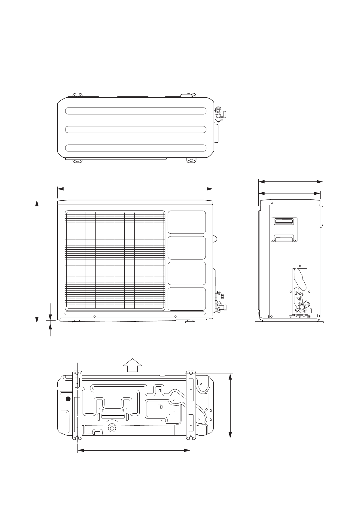
OUTDOOR UNIT
(unit : mm)
Models :
AOH12LMAKL
AOH14LMAKL
830
350
320
650
12
Bottom
Air flow
343
603
32006.05.25
Page 5
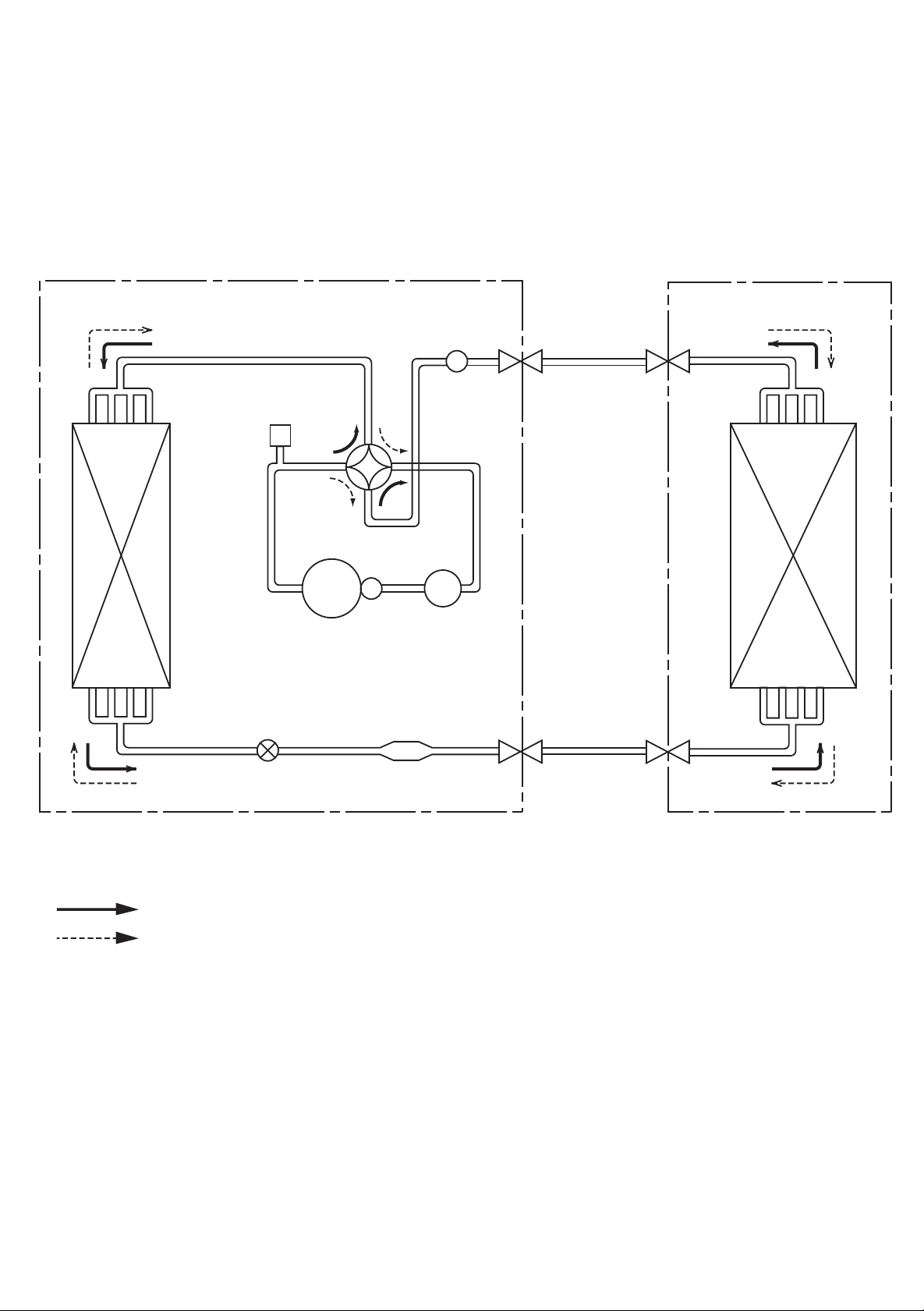
REFRIGERANT SYSTEM DIAGRAM
OUTDOOR UNIT
High
Pressure
Switch
Condenser
Expansion
Valve
4-Way
Valve
Compressor
Muffler
Accumulator
Strainer
INDOOR UNIT
Refrigerant Pipe
( Gas )
Evaporator
Refrigerant direction
Cooling
Heating
Refrigerant pipe diameter
ARH12LUAD
Gas pipe : 9.52 mm ( 3/8 inch )
Liquid pipe : 6.35 mm ( 1/4 inch )
ARH14LUAD
Gas pipe : 12.70 mm ( 1/2 inch )
Liquid pipe : 6.35 mm ( 1/4 inch )
Refrigerant Pipe
( Liquid )
42006.06.07
Page 6
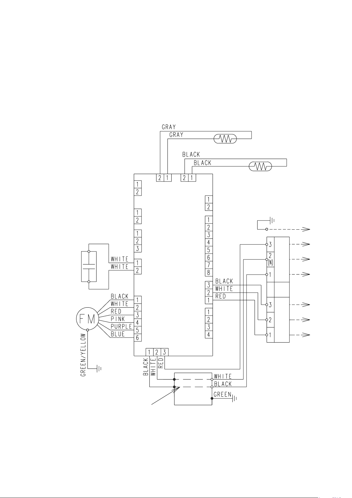
CIRCUIT DIAGRAM
INDOOR UNIT
Models :
ARH12LUAD
ARH14LUAD
Thermistor (pipe temp.)
Thermistor (room temp.)
Fan motor
capacitor
Fan motor
CN7
CN6
(drain pump)
CN11
(fresh air)
CN15
(float sw)
CN4
CN5
CN1
CN8
(heater)
(display)
Controller PCB
CN10
CN13
CN17
CN14
(HA)
Outdoor
Remote
Terminal
unit
to outdoor unit
control
to remote control unit
Use T 3.15A - 250V
Fuse on F101
Filter
board
52006.05.25
Page 7

OUTDOOR UNIT
Models :
AOH12LMAKL
AOH14LMAKL
62006.05.25
Page 8

INDOOR PCB CIRCUIT DIAGRAM
C6 4700P
<ECQM>
R5 62K
<RS - 2W>
D5
1SR139-600
D10
1SR139-600
C7 0.047
<ECQB>
D2
D1FL20U
D3
MTZJ5.1B
R7
330
<1/4W>
CN4
B2P3-VH-B-Y YELLOW
CN4-1
CN4-2
CN5-1
CN5-2
CN5-3
CN5-4
CN5-5
CN5-6
CN6-2
C105
0.01
<F>
C106
0.01
<F>
+
K2
G5SB-14
C3 0.22 <RE>
R88 120 <1/2W>
CN6-1
R6 100
<1/2W>
D4
D1FL20U
C8
100/6.3V
JM6
C101
0.22
<RE>
K4
G5NB-1A
TM101
TM102
UL1015 AWG14 BLACK
UL1015 AWG14 WHITE
UL1015 AWG14 RED
TERMINAL BOARD
REMOTE
CONTROL
UNIT
to outdoor unit
FH101
L
3.15A - 250V
N
E101 W103
UL1015 AWG16
GREEN
FAN MOTOR
F M
YELLOW / GREEN
1
2(N)
3
1
2(N)
3
POWER SOURCE
230V
50Hz
R1 3.3
<RC - 5W>
FH102
F101
<BET>
SA101
RA-362M
UL1015 AWG18 WHITE
FAN CAPACITOR
450V / 2.3uF
(ARY12,14,18)
450V / 2.5uF
(ARY22)
E
D1
D3SB60
C5
100/
450V
VA102 470V
<TNR>
VA101 470V
<TNR>
W104
UL1015
AWG18
BLACK
UL1015 AWG20 WHITE
UL1015 AWG20 WHITE
BLACK
WHITE
RED
PINK
PURPLE
BLUE
TO CONNECTOR No.17
R4 330K
<SPRH - 2W>
Q1
2SC4236
R3 100
<1/10W>
Q2
R2 1.5
<RS - 2W>
2SC1815
+
ELF17N015A
C103
0.022
<YE>
C104
0.022
<YE>
LF101
CN1 B3P5-VH-B-C BLACK
CN1-1
CN1-2
CN1-3
CN5 B6P11-VH-B WHITE
DRAIN PUMP
CN6 B2P3-VH-B-E BLUE
CUSTOM CODE
CUSTOM CODE
CUSTOM CODE
SWITCHING TRANSFORMER
T1
ZFT29B01
PRIMARY SECONDARY
K1
G5SB-14
K3
G5SB-14
TEST
SW1
DSS803
No.1
No.2
No.3
AUTO RESTART
ROOM TEMPERATURE CORRECTION
( HEATING OPERATION )
ROOM TEMPERATURE CORRECTION
( HEATING OPERATION )
D6
D2FL20U
C9
1000
/25V
C54
0.01
<F>
VA1 470V
<TNR>
C
SW2 DRS4016-5
18
14
10
SSR1
G3MC-201PL-VD
DC12V
VA2 470V
<TNR>
R21 - R24
10K <1/10W> x 4
CN9-1
CN9-2
CN9-3
CN9-4
CN9-5
CN9
B5P-SHF-1AA
WHITE
R17
JM1
JM2
JM3
+
R8 10K
<1/10W>
R29
8
4
2
1
5V
+
-
5V
R39 R38
10K <1/10W> x 3
R16
R15
14V
5V
I C2
7812
I O
G
I C3
7805
I O
G
10K <1/10W> x 4
R30 R31
I C 10 H I 2002
R93 10K <1/10W>
R94 10K <1/10W>
R95 10K <1/10W>
R96 10K <1/10W>
I C5 (5/7)
14V
uPA2003GR
K 2
K 1
K 3
K 4
I C6 (4/7)
uPA2003GR
5V
R37
5V
R18 1.0K <1/10W>
R19 1.0K <1/10W>
R20 1.0K <1/10W>
12V
C11
+
10/
25V
R59 R97
10K <1/10W> x 4
5V
C13
C14
0.1
<F>
R32
14V
9
11 6
12
13 4
14 3
15 2
12
13
14 3
15
R25 - R28
1.0K <1/10W> x 4
+
100/
6.3V
R33 - R36
1.0K <1/10W> x 4
5V
1
C26 - C29
0.01 <F>
x 4
10
8
5
2
3
R10
10K
<1/10W>
4
C17
0.01
<F>
5
5
4
2
C22 - C25
0.01 <F> x 4
10K <1/10W> x 3
R42 1.0K <1/10W>
R41 1.0K <1/10W>
R40 1.0K <1/10W>
0.01 <F> x 3
C21
0.01
<F>
R98 R99
C15
0.1
<F>
NC
I C5 (1/7)
7
uPA2003GR
R14 10K
<1/10W>
5V
Q3
DTC124EKA
C10 C12
C20
0.01
<F>
C47
0.1
<F>
R9 390
<1/10W>
C30
CR1
0.01
<F>
CR6
0.01
<F>
C19
0.01
<F>
1
2
3
54
55
66
65
74
68
75
7
4
67
33
72
56
57
58
59
41
42
63
40
39
38
37
36
52
51
49
48
43
44
45
46
19
20
21
P15
P16
P17
P122
P123
P05
P04
VDD0
VDD1
AVRF0
AVRF1
AVSS
VSS0
VSS1
XT2
P124
P125
P126
P127
P65
P66
P02
P64
P63
P62
P61
P60
P120
P37
P35
P34
P67
P30
P31
P32
P40
P41
P42
X1 X2
70 69
1
RESET
2
CONTROLLER PCB ASSY (main PCB)
ARH12LUAD : K01AL-0412HSE-C1
ARH14LUAD : K01AL-0411HSE-C1
P10
76
C32
1000P
<R>
77
P11
P70
P71
P72
P131
XT1
P46
P47
P57
P56
P36
P33
P50
P27
P26
P25
P22
P21
P20
P130
P51
P52
P53
P54
P55
P01
P00
P121
P03
P12
P13
P14
P45
P44
P43
I C
P24
P23
3
C35
1000P
<R>
8
9
10
6
73
25
26
35
34
50
47
27
18
17
16
13
12
11
5
28
29
30
31
32
62
61
Q5
2SC2712
53
64
78
79
80
24
23
22
C16
C31
71
15
14
60
C44
0.1
<F>
X1
CSTS0500MG03-T
I C5 (1/7)
7
5
3
1
5V
R60
10K
<1/10W>
3
2
I C6 (1/7)
uPA2003GR
CR7
R67 1.0K
0.01
<1/10W>
<F>
C43
5V
R55
10K
<1/10W>
R44 1.0K
<1/10W>
R46 1.0K
<1/10W>
R50 10K <1/10W>
VCC
DO
4
NC
D I
3
2
CK
NC
1
CS
GND
I C7
BR93L46RF
R77 - R79
10K <1/10W> x 3
6 11
I C6 (2/7)
1
16
uPA2003GR
uPA2003GR
161
10
6
11
12
I C4 (7/7)
14V
uPA2003GR
9
13
4
8
14
15
2
16
C40
0.01
<F>
5V
R61
10K
<1/10W>
3
Q6
1
2SC2712
2
R65 390 <1/10W>
107
R68 10K
<1/10W>
C1
0.1
<F>
CR2 - CR4
10K <1/10W> x 3
R81 1.0K <1/10W>
R72 1.0K <1/10W>
R71 1.0K <1/10W>
0.01 <F> x 3
5V
1
3
I C8
2
PST600C
8
7
6
5
R62 4.7K
<1/10W>
1
5V
R70
R56
C45
0.1
<F>
R43 10K
<1/10W>
(1%)
R45 49.9K
<1/10W>
(1%)
5V
C39
0.1
<F>
R57 1.0K
<1/10W>
BZ1
PKM13EPY-4000
R51 0.1 <1/10W>
R54 47 <1/10W>
CR5
1000P
<R>
12V
+
7
I C11-2
BA10358
5V
R69
10K <1/10W> x 3
R80
R58, R100
10K <1/10W>
x 2
B Z
R53
10K
<1/10W>
5
6
D7
DA226U
SW4
DSS803
No.3
No.2
No.1
R76
10K
<1/10W>
JM10
C34
0.1
<F>
C37
0.1
<F>
C49
0.01
<F>
5V
Q4
DTC124EKA
14V
C38
0.01
<F>
14V
5V
R52
10K
<1/10W>
12V
12V
R63 15.4K
<1/10W>
(1%)
R64 28K
<1/10W>
(1%)
12V
L2 0.022
<DSS306>
L4 0.022
<DSS306>
R66 10K
<1/10W>
L3 0.022
<DSS306>
I C11-1
BA10358
3
+
1
2
-
FUN DELEY SHIFT
FAN MOTOR TYPE SHIFT
REMOTE CONTROL UNIT TYPE SHIFT
5V
R75
10K
<1/10W>
R49 1.0K
<1/10W>
5V
C41
+
10/
25V
5V
5V
RJ2
10K
RJ1 1.0K
<1/10W>
<1/10W>
CN15-1
CN15-2
CN15-3
CN15 B3B-XARK-1-A RED
R48 10K
<1/10W>
5V
5V
R47 390
<1/10W>
CN10-1
CN10-2
CN10 B2B-XAMK-1-A GREEN
CN11 B2B-XARK-1-A RED
CN11-1
CN11-2
CN13 B8B-XASK-1-A
CN13-1
CN13-2
CN13-3
CN13-4
CN13-8
CN13-5
C42
0.01
<F>
CN13-7
CN13-6
CN17 B3B-XAKK-1-A BLACK
CN17-1
UL1430 AWG22 RED
CN17-2
UL1430 AWG22 WHITE
CN17-3
UL1430 AWG22 BLACK
CN8 B2B-XASK-1-A
CN8-1 BLACK
CN8-2 BLACK
CN7-1 GRAY
CN7-2 GRAY
CN7 B2B-XAKK-1-A BLACK
FLOAT SWITCH
CN14 B4B-XH-AM
CN14-4
CN14-3
JEM-A HA
CN14-2
CN14-1
HEATER
FRESH AIR
DISPLAY BOARD
ROOM TEMPERATURE THERMISTOR
PIPE TEMPERATURE THERMISTOR
TO TERMINAL BOARD
1 PIN
2 PIN
3 PIN
72006.07.14
Page 9

OUTDOOR PCB CIRCUIT DIAGRAM
CONTROLLER PCB ASSEMBLY
AOH12LMAKL : K03AV-0501HUE-C1
AOH14LMAKL : K03AV-0502HUE-C1
POWER SOURCE
220 / 240V
50Hz
TO
INDOOR UNIT-A
FAN CAPACITOR
FAN MOTOR
C200
450V
3.5uF
F M 1
4-WAY VALVE
PRESSURE SWITCH
COMP. THERMOSTAT
EXPANSION VALVE-A
M
HEATSINK
TEMP. TH.
DISCHARGED
TEMP. TH.
PIPE
TEMP. TH.
OUTDOOR
TEMP. TH.
EMI FILTER
RFC-8
F201 TLC
1T
25A - 250V
L
N
L
N
WHITE
BLACK
WHITE
B
3
UL1015
AWG16
GREEN
EARTH
RED
UL1015
AWG20 x 4
UL1015
AWG20
BLACK
UL1015
AWG20
BLACK
BLACK
WHITE
RED
BLUE
CN11 B4P7-VH-B
BLACK
BLACK
CN30 179844-1 WHITE
RED
RED
CN37 B2B-XARK-1-A RED
BROWN
BROWN
CN38 B2B-XAMK-1-A GREEN
CN27 B6B-XARK-1-A RED
CN25 B2B-XAKK-1-A BLACK
CN21 B2B-XH-AM YELLOW
CN22 B2B-XH-AM RED
CN23 B2B-XAEK-1-A BLUE
BROWN
BROWN
BROWN
BROWN
BLACK
BLACK
BLUE
BLUE
RED
BROWN
BLUE
ORANGE
YELLOW
WHITE
UL1015
AWG14
BLACK
W1
BLACK
B
W4
BLACK
W2
BLACK
B
W5
BLACK
B
W3
B
W8
W103
BLACK
W102 B
4
3
2
1
2
RE1202
1
1
2
1
2
12V
1
2
3
4
5
6
1
2
1
2
1
2
1
2
VA101
470V
<TNR>
VA102
470V
<TNR>
SA100
RA-302M
GREEN
RED
B
BLACK
CR5
5V
L202
BL02Rn1
L201
BL02Rn1
SERIAL A
R91
R90
R63 6.65K
<1/10W>
(1%)
R67 38.3K
<1/10W>
(1%)
CR1
RE1202
K11
G5SB-14
3
4
5
2.2K x 2
<1/10W>
C70C71
0.1 <F> x 2
5V
R65 56K
<1/10W>
(1%)
RCV2515-010PF05
C101
1.0
<LE>
K13
2
2 3
12V
4
+
1
G5NB-1A
3
12V
1
K17
G5NB-1A
1.0K <1/10W> x 2
R93
R92
C73
0.01 <F> x 2
1
4
12V
1
2
4
C72
R62 10K
<1/10W>
R64 10K
<1/10W>
R66 10K
<1/10W>
L1
2
3
C104
0.033
<YE>
C106
C105
1.0
0.033
<LE>
<YE>
PFC5000-0502
x 2
FH1
F4
250V - 5A
<BET>
18
14
8
7
12V
D28
SLR-332
<RED>
R43
2.2K <1/10W>
C37
0.1
<F>
C38
0.1
<F>
C39
0.1
<F>
C43
0
C44
0
C45
0
TM100
FH2
2
O1
7
O2
9
O3
16
O4
4
GND1
5
GND2
12
GND3
13
GND4
I C4
TD62064
3
HY I C1
HU2001
10
6
COM1
COM2
NC1
NC2
I 1
I 2
I 3
I 4
R44 6.65K
<1/10W>
(1%)
L2
N200500K
54
CT1
CT-1B
R60 1.0K
<1/10W> (1%)
1
4 3 2
5
3
4
5
5V
I C3-5 M54523
I C3-6 M54523
I C3-4 M54523
I C3-2 M54523
I C3-1 M54523
I C3-7 M54523
I C3-3 M54523
3
6
11
14
12V
1
8
10
15
5V
R47
2.94K
<1/10W>
(1%)
I C14-1
uPC393
R45 10K
<1/10W>
C107
3.3
<LE>
5V
1
2
5V
1
2 1
R51 27K
<1/10W>
5V
R50
10K
<1/10W>
R52 1.0K
<1/10W>
5V
R53
10K
<1/10W>
12
11
13
15
16
10
14
R97
R96
R95
R94
1.5K <1/10W> x 4
R46
2.87K
<1/10W>
(1%)
C75
0.1
<F>
5V
2
-
1
3
+
C74
0.1
<F>
5V
R11
10K
<1/10W>
RCV2515-010PF05
1 2
D60
DAN217U
3
C60
+
220/16V
<PJ>
R61 3.74K
<1/10W> (1%)
R55 1.0K
<1/10W>
R56 27K <1/10W>
3
Q51
1
2SC2412K
2
<BQ>
5
6
4
2
1
7
3
5V
R49
10K
<1/10W>
R42 1.0K
<1/10W>
C76
0.1
<F>
L4
VR1
B2K
C51
0.022 <F>
C77
0.1
<F>
C111
1.0
<LE>
34
R68 22K
<1/10W>
C40
0.1
<F>
C53
0.022
<F>
C64
0.1
<F>
12V
4
1
K101
DW12D1
<1/10W>
MB90F462APFM-
17
16
35
59
58
60
21
34
47
27
28
29
30
31
32
33
57
41
42
43
44
10
22
23
1
2
R200
ZPR0RCH400
3
2
C114
1.0 <LE>
R437 270
<1/10W> (1%)
R438 270
<1/10W> (1%)
5V
R404
510
2
0.1 <F> x 2
I C 1
G-204-E1
VCC
AVCC
P62
2
P00
P46
P01
P12
P50
3
P17
P13
P37
P14
P36
P40
P15
MD2
P16
AVR
P11
P24
P26
P25
P02
P30
P03
P31
P04
P32
P05
P33
P06
P34
P07
P35
P10
P60
C
P61
P20
P21
MD0
P22
MD1
P44
P23
P43
P57
P42
P56
9
P41
8
P55
P45
P54
7
RSTX
P52
5
6
P27
P53
AGND
4
P51
GND
X0
X1
GND
3
X1
8.00MHz
<EF0EC>
2
3
D101
D25XB60
1
2
3
I C402
PS2561L-1-V
Q401
1
DTC114EKA
C19 C18
56P63
11
R608 10K
25
<1/10W>
26
40
36
37
38
39
12
45
46
50
51
52
53
54
55
14
15
18
20
64
63
62
61
1
19
48
13
24
49
CHOKE COIL
L=0.3MH 30A
UL1015
W10
RED
AWG14
W11
BLACK
1
2
3
4
RED
BLACK
UL1015
AWG14
+
-
BROWN
RED
ORANGE
UL1007
AWG24
10K
<1/10W>
035
0.01
<F>
x 2
+
-
C415
0.01
<F>
A
18V
4
3
1
4
18V
A
CN407
C413
B4B-XASK
0.01
-1-A WHITE
<F>
A
ACTPM CONTROL
C115
0.1
<HCP>
<1/10W>
C95
R114 27K
100P
<1/10W>
<CH>
5V
+
I C201
BR93LC46
8
1
CS
C20 <PS>
4.7/50V
5V
VCC
4
2
SK
DO
7
3
D I
NC
GND
R205 10K
5
6
NC
JM207
R78
R75
R76
R77
U
X
V
Y
W
Z
R79
5V
R19 10K
<1/10W>
R72 1.0K
<1/10W>
C17
0.01
<F>
C16
+
4.7/50V
<PS>
2
SUBNCVCC
1
I C6
BD4742G
R73 82K
<1/10W>
5
4
VOUT
3
GND
L1
C414
SACT32010A
ACTPM
YELLOW
5V
R407
R403
036
0.01
<F>
5V
R113
1.0K
5V
C91
0.01
<F>
<1/10W>
5V
R74
10K
<1/10W> x 6
5V
TERMINAL 2P
EMI FILTER
TFC-25
-15-12
2T
L2
P
N1
I C400-1
uPC393
18V
1
4
<1/4W>
23
I C401
PS2561L-1-V
18V
1
4
2
3
I C404
PS2561L-1-V
5V
R103 4.7K
Q91
<BQ>
<1/10W>
2SC2412K
3
1
2
560 <1/10W>
x 6
EMI FILTER
C204
1200 450V
WHT
+
PURPLE
UL1015 AWG14
18V
R436
1
3.3K
I C400-2
uPC393
7
R442
3.3K
<1/4W>
8
6
5
I C13
PS8602
I C11-2
uPC393
R310 - R315
100 <1/10W> x 6
R316 - R321
100 <1/10W> x 6
R85
R84
R83
R82
R81
R80
I C301 - I C306
PS2561L-1-V x 6
R605 22K
<1/10W>
RFC-8
TM104
1T
YEL
TM105
BLUE
18V
C409
10/
25V
<PS>
+
D402
RD3.3ES <B2>
8
C411
2
-
0.01 <F>
3
+
A
6
-
5
+
<1/10W> x 2
A
A
C414
C412
0.01
0.1
<F>
<F>
15V
R102
1.6K
<1/4W>
2
2
-
1
3
3
+
I C11-1
uPC393
6
-
7
5
+
5V
1
2
1
2
1
2
1
2
1
2
1
2
10K <1/10W> x 5
R21
R604
R20
10K
<1/10W>
A
C87
470P
<CH>
5V-2
4
3
4
3
4
3
4
3
4
3
4
3
R322
R603
R435
R441
R201 220K
<2W>
A
R402 S3.3K
<1/4W>
1.0K
<1/10W>
(1%) x 2
C89
470P
<CH>
R323
R324
330 <1/10W> x 6A
5V
R602
R601
R400
R440
R406
2.87K
R401
2.94K
A
15V
R325
180K <RN - 1/2W>
C88
0.1
<F>
A
R326
5V
7
8
9
10
C116
0.1 <HCP>
(1%) x 2
<1/2W>
1
1
1
1
1
R327
1
2
3
4
5
6
L100
BARE WIRE
SN-PLATED
DIA 0.65MM
Q1
2SC4236
2
1
3
R140
D1
1.2
D1FL20U
DAN217U x 2
D81 D82
2
2
1
3
3
R105 2.49K
<1/10W> (1%)
R108 2.87K
<1/10W>
(1%)
R328 - R333
5V-2
1.0K <1/10W> x 6
3
2
3
2
3
2
3
2
3
2
3
1
Q301
2
Q302
Q303
Q304
Q305
Q306
2SC2412K
<BQ> x 6
CN601
B10B-PASK-1 WHITE
TAUX
TTXD
TRXD
TMODE
TAUX3
TCK
/ TRES
/ T I CS
FH3 PFC5000-0502
F2 250V
<BET> 3.15A
FH4 PFC5000-0502
R2 1.0K
<RS - 3W>
R1
220K
C1 220P
<2W>
<BN>
R3 100
C2 0.047
<1W>
<ECQB>
D1FL20U
D10
RD5.6ES
<B2>
100/16V
<PJ>
R4 330
<1/4W>
R104
195K x 6 (1%)
<RN - 1/2W>
1
R106
R87 2.94K
<1/10W>
(1%)
R107 680
<1/10W>
(1%)
A
R360
39
<1/2W>
A
C316
C314
C315
2200P <B> x 6
FLASH
D2
C3
R111
R112
R110
C313
C4
T1
15V
+
1
2
3
6
7
8
I C101
TA7805
1
I
D8
D1FL20U
D7
D1FL20U
3
O
G
+
2
C10
100/16V <PS>
R5 10K
<1/10W>
D401
D1FL20U
C406
220/50V
<PJ>
5V-2
C11
0.1
<F>
A
JPZ-200
16
15
13
12
10
9
D100
D1FL20U
+
C7
220/
35V
<PJ>
195K x 6 (1%)
R86
<RN - 1/2W>
470/25V
<PJ>
+
C5
220/16V
<PJ>
TA7805
1
+
+
1
G
2
I C407
uPC24M18
I C8
I
O
12V
5V
O
C6
G
+
2
100/16V
<PS>
18V
33I
C418
+
10/35V
<PS>
A
R89
R88
5V
I C307
R33
PS2561L-1-V
C33
0.01
<F>
UP
VP I
VUFB
VUFS
VP
VP I
VVFB
VVFS
WP
VP I
VPC
VWFB
VWFS
A
VNC
C IN
CFO
VN I
FO
UN
VN
WN
P
U
V
W
N
10K
<1/10W>
C34
0.01
<F>
<1/10W>
14
15
16
17
18
19
20
21
22
23
24
25
26
R303
4.7K
C332
0.1
<F>
C327
0.022
<F>
4
3
15V
5V-2
R302 1.0K
A
<1/10W>
A
C328
2200P
<B>
A
5V-2
1
2
R301
R304
560
<1/10W>
0.02
<5W>
x 2
TM303
W
BLACK
R305
A
TM304
TM305
U
V
RED
WHITE
R40 1.0K
<1/10W>
15V
47/35V <PJ> x 3
330K <1/10W> x 3
U1JU44 x 3
0.1 <F> x 3
+
R361
D301
C323
C305C304
+
C322
D302
R363
+
C321
R362
D303
15V
A
15V
A
15V
C312
C311
A
C324 - C326
0.1 <F> x 3
I C310
C303
PS21246
1
2
3
4
5
6
7
8
9
10
11
12
13
C M
C46
0
82006.07.14
Page 10

ERROR CONTENTS
INDOOR UNIT
(1) Stop the air conditioner operation.
(2) Press the master control button and the fan control button si-
multaneously for 2 seconds or more to start the test run.
Test run display
(3) Press the start/stop button to stop the test run.
SELF-DIAGNOSIS
When the error indication "E:EE" is displayed, follow the following
items to perform the self-diagnosis. "E:EE" indicates an error has
occurred.
REMOTE CONTROLLER DISPLAY
(1) Stop the air conditioner operation.
(2) Press the set temperature buttons simultaneously for 5
seconds or more to start the self-diagnosis.
Refer to the following tables for the description of each error
code.
Unit number (usually 0)
SUMOTUWETH FR
EX. Self-diagnosis
(3) Press the set temperature buttons simultaneously for 5
seconds or more to stop the self-diagnosis.
Error code
SA
Error code Error contents
00
01
02
03
Communication error
(indoor unit remote controller)
Communication error
(outdoor unit indoor unit)
Room temperature sensor open
Room temperature sensor short-circuited
Indoor heat exchanger temperature sensor open
04
05
Indoor heat exchanger temperature sensor shortcircuited
Outdoor heat exchanger temperature sensor
06
08
Power source connection error
09
0A
0c
11
12
13
14
15
16
17
Float switch operated
Outdoor temperature sensor
Discharge pipe temperature sensor
Model abnormal
Indoor fan abnormal
Outdoor signal abnormal
Outdoor EEPROM abnormal
Compressor temperature sensor
Pressure switch abnormal
IPM error
1A
1b
92006.05.24
Compressor cannot operate
Outdoor fan abnormal
Page 11

OUTDOOR UNIT
(1) Is there any abnormal noise and vibration during operation ?
(2) Will noise, wind or drain water from the unit disturb the
neighbors?
(3) Is there any gas leakage?
Do not operate the air conditioner in the test running state
for a long time.
For the operation method, refer to the operating manual
and perform operation check.
Error contents
Serial signal error
Discharge pipe thermistor error
Heat exchanger thermistor error
Outdoor temperature thermistor error
Compressor thermistor error
Pressure switch error
Current trip error
CT error
Compressor position detection error
LED (Red)
1 time blink
2 times blink
3 times blink
4 times blink
7 times blink
8 times blink
10 times blink
11 times blink
12 times blink
Compressor starting error
Timer error
13 times blink
14 times blink
102006.05.24
Page 12

DISASSMBLY ILLUSTRATION
Models :
ARH12LUAD
ARH14LUAD
160
587
235
184-1
146
287
173
74
762
464
196-2
588-2
147
63
588-1
761
173
625
244
381-4
173
112006.04.27
Page 13

Models:
ARH12LUAD
ARH14LUAD
122006.04.27
Page 14

Models :
ARH12LUAD
ARH14LUAD
143-1
287
380
514
236
195
34
875
455
982-2
982-1
381-4
815-1
240
132006.04.27
Page 15

Models :
AOH12LMAKL
AOH14LMAKL
527
14
7
734
64
4
5
2
142006.04.27
Page 16

Models :
AOH12LMAKL
AOH14LMAKL
13-3
349
17
346-1
16
343
344
29
334
754
109
46
85
13-2
345-2
345-1
346-2
273-1
348
335
108
361
273-2
12
33
411
55
45-2
31
45-1
45-3
41
39
45-4
26-2
26-1
152006.04.27
Page 17

PARTS LIST
INDOOR UNIT
Ref.
No.
109 Casing Assy
126 Motor Fixing Table Assy
138 Panel Assy (Motor)
143-1 Clamp NK-3N
146
147 Inlet Pipe (Eva.) Assy
160 Drain Pan Assy
164
173 Hook Metal
184-1 Thermo. Spring-A
195 Binder C SKB-100
196-2 Binder M SKB-150
234 Thermistor Assy-Room
235 Thermistor Assy-Pipe
236 Controller PCB Assy
Description
34 Capacitor (Fan Motor)
56 Sirocco Fan Assy
63 Front Panel Assy
67 Rubber (Vibration - proof)
74 Air Filter
Evaporator Assy
Fan Motor Assy
(MFA-18NTT)
Part No.
ARH12LUAD ARH14LUAD
9900270179
9358621004
9363723007
313659068604
9366833017
9363322002
9358591000
9363401004
313361274700
9373255024
9373034063
9364502045
9600778210
9363195002
313728262708
313361275805
313035356905
9703299018
9703297090
9704557988
(KO1AL-0412HSE-C1) (KO1AL-0411HSE-C1)
9900270179
9358621004
9363723007
313659068604
9366833017
9363322002
9358591000
9363401004
313361274700
9373255024
9373034063
9364502045
9600778210
9363195002
313728262708
313361275805
313035356905
9703299018
9703297090
9704557971
Ord.
Q'ty
240
244
287 Cap (Power)
338 Motor Fixture
380
381-4 Spacer
455 Control Box
464 Cover (Cabinet)
514 Control Box Cover
587
588-1 Bracket Eva. R
588-2
625 Cord Bushing
653-1 CUP SCREW
734 Panel Top
761 Side Panel-R Assy
762
815-1 Terminal 7P
875
982-1 Cord Clamp
982-2 Cord Clamp-B
Remote Control Unit
Cover (Piping)
Locking Spacer
Support Plate (Eva.) 93634040059363404005
Bracket Eva. L
Side Panel-L Assy
Filter PCB Assy
9372266014
9363327007
9352173011
9358594001
313209391403
0600118075
9366299004
9363400007
9363201000
9363199000
9363198003
9359240006
9385089020
9363504002
9363507003
9363505009
9703403019
9704561251
9356857009
9356858006
9372266014
9363327007
9352173011
9358594001
313209391403
0600118075
9366299004
9363400007
9363201000
9363199000
9363198003
9359240006
9385089020
9363504002
9363507003
9363505009
9703403019
9704561251
9356857009
9356858006
162006.07.14
When you order parts, please make a photocopy of this page
and fill the number of the parts in the "Order" column.
Page 18

OUTDOOR UNIT
Ref.
Description
No.
2 Fan Guard 9371187013 9371187013
4 Emblem-Rear 9372171011 9372171011
5 Front Panel, Painted 9371924014 9371924014
7 Connector Cover (Cabinet) 9366398004 9366398004
12 Base Assy, Painted 9371920078 9371920078
13-2 2-Way Valve 9372204054 9372204054
13-3 3-Way Valve 9372205051 9372205051
14 Valve Cover 9372796016 9372796016
16 Condenser Assy 9372181096 9372181096
17 Thermistor Holder Pipe 313714262805 313714262805
26-1 Compressor Cover-A 9373730019 9373730019
26-2 Compressor Cover-B 9373730026 9373730026
29 Separate Wall 9372795019
31 Controller PCB Assy 9705285064
33 Control Cover 9372792018
39 Propeller Fan Assy 9366378013
41 Fan Motor Assy-IN 9601671046
45-1 Motor Bracket 9371929019
45-2 Motor Bracket-Top 9371931012
45-3 Motor Bracket-Center 9371930015 9371930015
45-4 Motor Bracket-Bottom 9371932019 9371932019
46 Compressor Assy 9373262015 9373262015
55 Special Nut M8 9355091008 9355091008
64 Side Panel-L, Painted 9371926018 9371926018
85 Valve Plate, Painted 9371928012 9371928012
108 Rubber Seat (For Comp. ) 9358080009 9358080009
109 Terminal Cover (For Comp. ) 9373264019 9373264019
273-1 Strainer Assy 9372524015 9372524015
273-2 Joint Pipe (2-Way)-A 9373729549 9373729549
334 Accumulator 9368391003 9368391003
AOH12LMAKL AOH14LMAKL
Part No.
9372795019
9705285071
9372792018
9366378013
9601671046
9371929019
9371931012
Ord.
Q'ty
335 Accumulator Holder Rubber 9354022010 9354022010
343 Solenoid 9900165079 9900165079
344 4-Way Valve 9900163013 9900163013
345-1 Muffler 9372369029 9372369029
345-2 Joint Pipe (3-Way) 9373729556 9373729556
346-1 Expansion Valve Assy 9373729518 9373729518
346-2 Coil (Expansion Valve) 9900057022 9900057022
348 Pressure Switch Assy 9373729044 9373729044
349 Capillary Assy 9373729433 9373729433
361 Accumulator Support Assy 9372252017 9372252017
411 Gasket 9373266013 9373266013
527 Protective Net 9371934013 9371934013
734 Top Plate 9371925011 9371925011
754 Rubber Washer 9358078006 9358078006
---- ACTPM 9703457012 9703457012
---- Capacitor, Elec. 9705387010 9705387010
---- Fuse 0600086039 0600086039
---- Fuse Holder 0501454012 0501454012
---- Capacitor, Plastic 9900270049 9900270049
---- Terminal-5P 9900203023 9900203023
---- Terminal-2P 9701971015 9701971015
---- Hex. Bolt Socket 0700145148 0700145148
---- Clip (Cable) 9352715006 9352715006
---- BR Sheet 9363708042 9363708042
---- Relay 9900117016 9900117016
---- Compressor Presure Switch 9900186012 9900186012
---- Compressor Thermal Switch 9373263012 9373263012
---- Discherge Temperature Thermistor 9704219039 9704219039
---- Heat Exchanger Thermistor 9900374020 9900374020
---- Outdoor TemperatureThermistor 9900378011 9900378011
---- Heat Sink Thermistor 9900195014 9900195014
When you order parts, please make a photocopy of this page and
172006.07.14
fill the number of the parts in the "Order" column.
Page 19

STANDARD ACCESSORIES
INDOOR UNIT ACCESSORIES
Name and Shape Q'ty Application Part No.
Installation
template
For positioning the indoor unit
1
9364225005
Hanger
Tapping screw
( 4 x 10)
Special nut A
(large flange)
Special nut B
(small flange)
Coupler heat
insulation
(large)
Coupler heat
insulation
(small)
Binder
Remote
controller
For suspending the indoor unit
from ceiling
4
For installing the hanger
8
For suspending the indoor unit
4
from ceiling
4
For indoor side pipe joint
(large pipe)
1
For indoor side pipe joint
(small pipe)
1
(Small)
For remote controller and remote
1
controller cord binding
(Large)
For fixing the coupler heat
4
insulation
Heat & Cooling model
1
9363195002
0700009037
313005446653
313005446759
9350716029
9352766015
313361275805
312300787605
9372266014
Remote
controller cord
Tapping screw
( 4 x 16)
Filter
Drain hose
insulation
For connecting the remote
1
controller
For instaling the remote
controller
2
For instaling to indoor unit
3
Insulates the drain hose and
vinyl hose connection
1
OUTDOOR UNIT ACCESSORIES
Drain pipe
Drain cap
Adapter D (1/2" 3/8")
12.70mm 9.52mm
For outdoor unit drain
piping work
1
[Heat & Cool model
(Reverse cycle) only]
1
For use when connecting
model 12,000 BTU/h
1
9372714010
0700181108
9366833017
313806217708
Part No.ApplicationQ'tyName and Shape
9303029015
313166024302
9370244007
182006.05.24
Page 20

0603G3058
 Loading...