


8351A

Operating Manual
8260A, 8351A, 8250A and 8240A
Introduction
Congratulations and a thank-you for the purchase of this Genelec SAM system. All Genelec SAM systems are designed to integrate easily into the digital production environment. There are
several ways to configure and operate SAM systems for a wide
variety of high quality audio applications. The SAM monitors
also have analog inputs, making them versatile and intelligent
replacements for standard analog monitors.
This manual addresses the setup and use of the 8240A, 8250A,
8351A and 8260A SAM monitors in stand-alone mode without
the Genelec Loudspeaker Manager GLM™ and the proprietary
Genelec monitor control network. Use with the GLM™ is described in the GLM™ System Operating Manual.
LISTENING
POSITION
MICROPHONE
GLM
NETWORK
GLM
NETWORK
USB
GLM
NETWORK
System
Genelec 8240A, 8250A, 8351A and 8260A are designed for
precise monitoring of 24 bit/192 kHz AES/EBU digital audio signal or line level analog audio signal. They are fully compatible
with Genelec Loudspeaker Manager GLM™ and the proprietary
Genelec monitor control network, and Genelec 7260A, 7270A
and 7271A SAM Subwoofers, but can also be used independently of these. The 8240A, 8250A, 8351A and 8260A feature
high SPL output, low colouration and broad bandwidth in a small
enclosure size. They are suitable for a wide variety of tasks,
such as near field monitoring, mobile vans, broadcast and TV
control rooms, multichannel sound systems and home studios.
The Minimum Diffraction Enclosure™ (MDE™), advanced Directivity Control Waveguide™ (DCW™) and Minimum Diffraction Coaxial (MDC™) technologies provide excellent frequency
balance even in difficult acoustic environments.
Amplifiers
The amplifier unit is mounted in the rear of the monitor enclosure.
The unit incorporates special circuitry for driver thermal overload
protection. Variable input sensitivity allows accurate level matching to console output section.
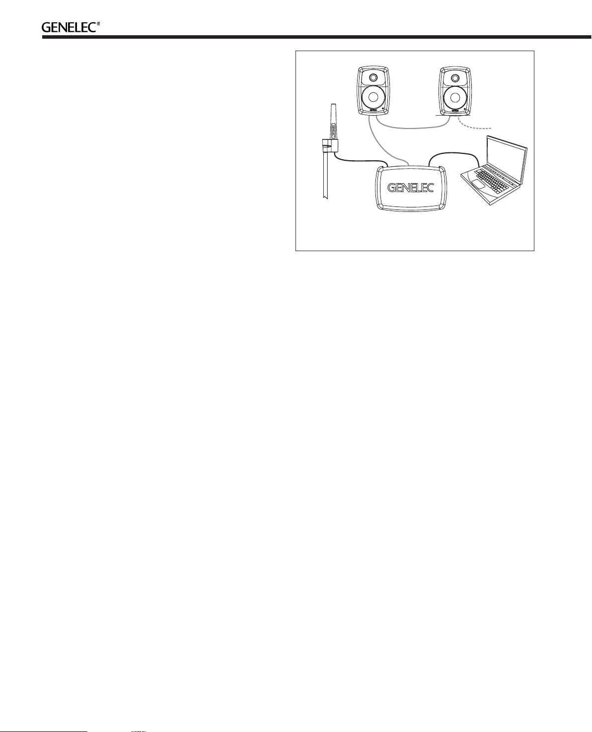
Setting Up the GLM™ Control Network
Although the
without the GLM
their full potential when set up and calibrated using the GLM™
software. The setup is fast and consists of the following steps:
1. Run a CAT5 (RJ45) cable from the monitor control network
to the next monitor (see Figure 1).
2. Run the final cable to control network input of the GLM
Adapter device.
3. Connect the GLM Adapter device to your computer USB
connector. The cable
4. Place the Genelec measurement microphone at the listen-
8240A, 8250A, 8351A and 8260A can be used
™ software and control network, they only reach
is a part of the GLM User Kit
.
Figure 1. GLM control network cabling
ing location of the engineer, on a stand, with the microphone
pointing upwards and the microphone top at the height of the
engineers ear in normal working position. The microphone is
a part of the GLM User Kit.
5. Run the microphone cable to the microphone input in the
GLM Adapter device.
6. Download GLM software at the Genelec web site (www.
genelec.com). Install the GLM software.
7. Follow the GLM software instructions to measure and set
up your monitors.
8. If you plan to not use a computer for controlling the monitors, use the GLM software to write the setting into the monitors (“Store the Settings”).
Using the Monitors in Stand-Alone Mode
When the monitors are not connected to a Genelec monitor control network, they operate in the stand-alone mode. However, settings made with the Genelec Loudspeaker Manager software can
be saved into each monitor and applied even when the network
is disconnected by setting switch 1 “STORED/MANUAL CONTROL” on switch group 2 of each monitor to position “STORED.”
All issues concerning use with the network are explained in detail
in the System Operating Manual provided with the GLM™ Loudspeaker Manager software kit.
Connections
Each monitor is supplied with a mains cable, one 5 m GLM network cable and an operating manual. Before connecting up, ensure that the mains switch is off.
2
Mains power
switch
GLM Control
Network
connectors
Mains input
connector
12V Remote
connector
(8260A only)
SWITCH
1
ROLL-OFF
-2dB -4dB
MAINS INPUT230 V~
50/60Hz 330W
BASS
BASS
TILT
-4dB
-2dB -4dB
+2dB -4dB
160Hz
-6dB -6dB -2dB
REMOTE
SERIALNUMBER
1
2
TREBLE
STOREDDESKTOP
TILT
AB
ON
OFF
MANUAL
ON+ON
OFF+OFF
CTRL
12 V
DIGITALIN
AES/EBU
8260A DSP TRI-AMPLIFIED
MONITORING SYSTEM
MAGNETICALLYSHIELDED
MADE INFINLAND
ON
OFF
ON
OFF
DIGITAL THRU
DRIVERMUTE
WF COAX
SUMAANDB
AES/EBU
www.genelec.com
-8
-6
-10
-4
-2
-12
0
dB
SYSTEMLVL.AES/EBUCH.
SWITCH
-10-20
2
-30
dB
ANALOG
IN
292-8260T-6
Stand-alone user
interface level control
Stand-alone user
interface switch
groups 1 and 2
Analog input connector
Digital Thru connector
Digital input connector
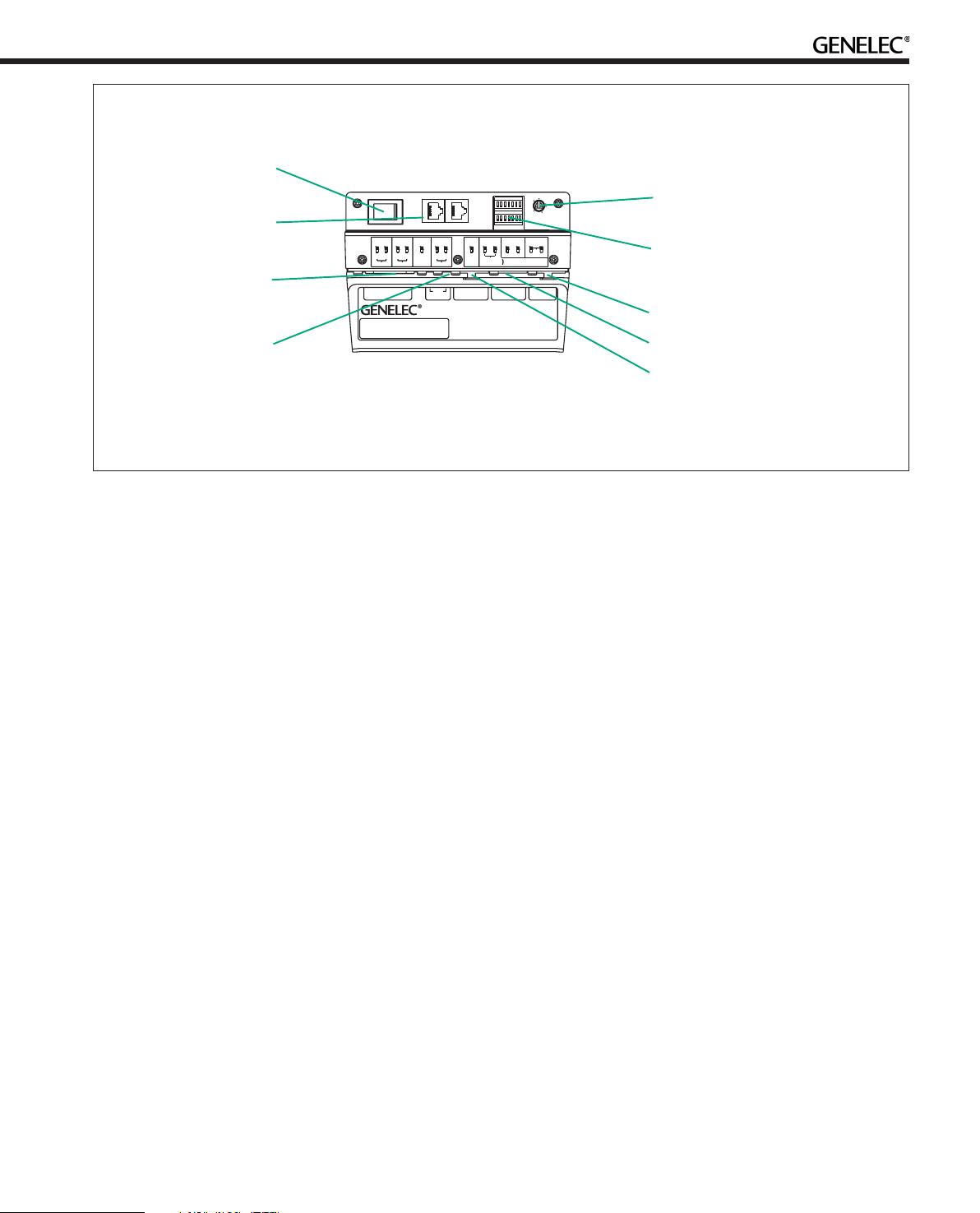
Figure 2. Connectors and controls on the back panel of a 8260A. The 8351A is similar. 8240A and 8250A share the same
layout but without the 12 V trigger voltage connector.
“MAINS INPUT” Connector
Connect the mains supply to this connector.
“DIGITAL IN AES/EBU” Connector
Use this female XLR connector for AES/EBU formatted digital
audio input signals. This input is selected automatically when a
valid digital audio signal is present, and overrides the analog input.
Depending on the digital hardware, transmission of a 192 kHz
sample rate is achieved using a double speed, single channel/
cable interface. This is called dual-wire mode. In this case one
cable per channel is used and no channel selection is required.
Dual-wire mode is automatically detected by the input stage.
If the digital source device has a volume fader that controls the
digital level, it may be advantageous to lower the level control
either on the computer interface or on the monitor’s back panel
controls, which in turn will force the use of more of the digital [bit]
resolution in the volume control.
If the digital inputs are used, all audio outputs are referenced to 0
dBFS (digital Full Scale, the largest level that may be represented in the AES/EBU signal). These monitors produce 100 dB SPL
at 1 meter in free space for a digital input signal of –30 dB FS.
“DIGITAL THRU AES/EBU” Connector
This male XLR carries an unaltered copy of the digital signal fed
into the “DIGITAL IN AES/EBU” connector. It can be used for
daisy-chaining up to four monitors together.
level is +7.0 dBu RMS on models 8240A and 8250A and +22.0
dBu RMS on models 8351A and 8260A. When A/D converter
input clip occurs the front panel light turns momentarily red, indicating the overload condition.
“CONTROL NETWORK” Connectors
Use these RJ-45 sockets to connect the monitor to the proprietary Genelec Loudspeaker Manager™ (GLM™) network only.
This connector is not Ethernet LAN compatible. Do not connect
to Ethernet LAN.
“12 V REMOTE” Connector (8260A only)
You can set up remote controlled powering up and down of the
8260A with 12 V voltage connected to this connector. The minimum current needed to actuate this function is 70 mA.
Front Panel Warning Light
Normally the light on the front panel of a SAM monitor is green,
indicating that the monitor is in normal operational mode.
The overload light (red) is activated by several events:
• exceeding the maximum input range of the analog input
• the digital input level is less than 0.1 dB from the digital full
scale
• exceeding the output capacity of the power amplifier
(clipping in the power amplifier) and thermal
overload of the power amplifier or drivers (thermal
protection has activated)
• an error is detected in the AES/EBU audio data
“ANALOG IN” Connector
Use this connector for analog audio signals. The maximum input
If a red warning light appears, turn the analog source down! If
the levels are already modest and a digital signal is being used,
3
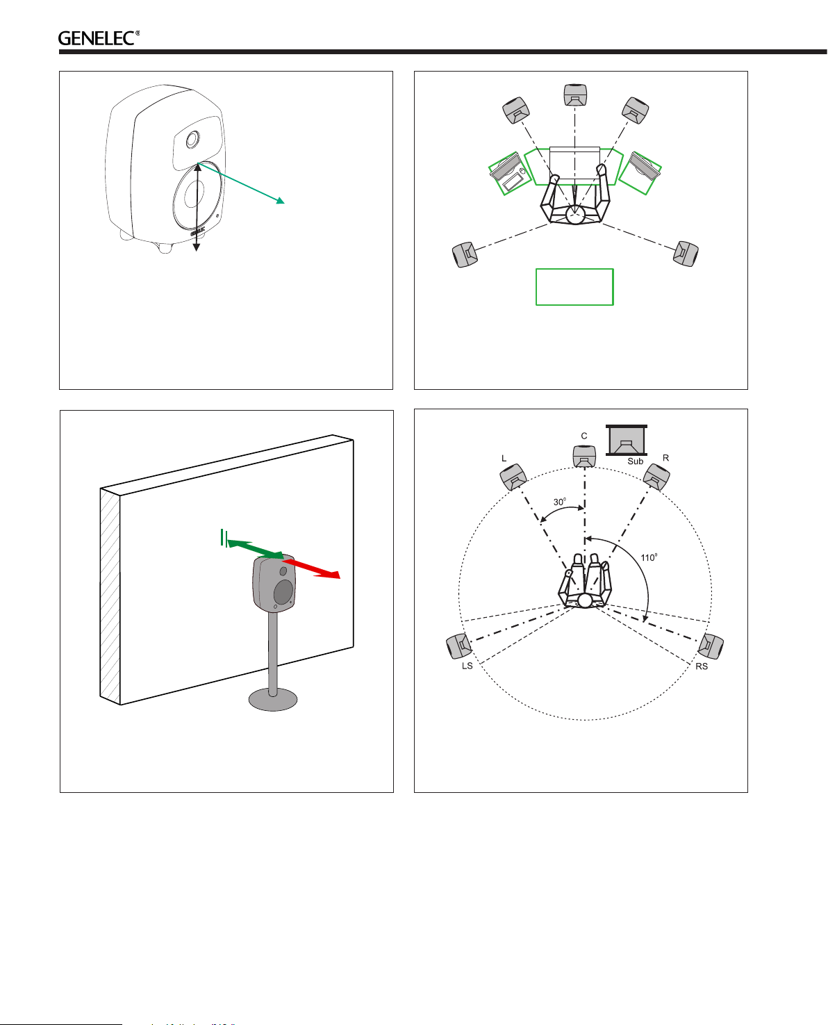
h
> 0,7 m
ACOUSTIC
AXIS
8240A: h=240 mm (9 7/16 )
8250A: h=290 mm (11 1/2 )
8351A: h=235 mm (9 1/4 in)
8260A: h=448 mm (17 5/8 )
Figure 3. The location of the acoustic axis is on the centerline of the monitor at the given height “h”. The acoustic
axis of the 8351A and 8260A is located at the center of the
coaxial driver.
in
in
in
Max
60 cm
Min 5 cm
Avoid
> 60 cm
Figure 4. Symmetrical layout and keeping the acoustic axis
clear from obstructions minimizes reflection surfaces and
maintains accurate localisation because reflections are symmetrical.
Figure 5. Recommended distances from a single wall to the
front baffle of free-standing monitors. Correct (green) and
not recommended (red).
ensure that there are no bit errors in the AES/EBU digital audio
data.
Mounting Considerations
Align the Monitors Correctly
Place the monitors so that their acoustic axes are aimed towards
the listening position (see Figure 3). Vertical placement is prefer-
4
Figure 6. Recommended monitor positioning for 5.1 multichannel audio reproduction
able, as it minimises acoustical cancellation problems around the
crossover frequency.
Maintain Symmetry
Check that the monitors are placed symmetrically and at an
equal distance from the listening position. If possible, place the
system so that the listening position is on the centerline of the
room and the monitors are placed at an equal distance from the
centerline (See Figure 4).
 Loading...