


Genelec 1094A and 1092A |
Operating |
Active Subwoofer Systems |
Manual |

Genelec 1094A and 1092A Subwoofers
General Description
The Genelec 1094A and 1092A active subwoofersarepowerfullowfrequency loudspeakers, incorporating all the amplifier and crossover electronics needed to combine them with other loudspeakers and amplifiers.
Drivers
The 1094A contains a single 385mm (15") long throw cone driver, housed in a 110 litre vented cabinet. A cavity over the driver boosts the drivers efficiency and acoustically attenuates possible distortion components. The 1092A utilises two 210mm (8") cone drivers, housed in a 55 litre vented cabinet, and employs driver front loading.
Crossovers
The 3+1 channel active crossover within the amplifier unit filters the low and high frequency components of the three front channels, dividing the input signals between the subwoofer and the main monitors. A separate subwoofer input connector allows for complete compatibility with digital 5.1 channel surround sound systems.
The crossover filter also provides calibrated ‘Bass Roll-off’ and ‘Phase’ controls, minimising the effects of the room on the performance of the subwoofer.
Amplifiers
The amplifier unit is mounted in the rear of the cabinet on quick release vibration isolators to ensure rattle free operation and long term reliability. The 1094A and 1092A amplifier output powers are 400W and 180W respectively. The amplifiers incorporate special driver protection circuitry for driver overload protection.
Installation
B a la n c e d |
|
B a la n c e d |
|
I n p u t s |
F8I5L THEzR |
O u t p u t s |
|
C R O S S O V EHRP |
|
||
L |
|
L |
|
C |
|
C |
|
Su b |
|
|
|
R |
|
R |
|
|
0 ° |
P o w e r |
|
|
2 7 09°0 ° |
||
|
A m p lif ie r |
||
|
1 8 0 ° |
||
|
|
||
S e n sLitP ivBita syPs h a s e |
|
||
± 6 d8B5 HR zo ll - o f f |
|
||
|
|
P o w e r s u p p |
|
D r iv e r |
S t a r t / S t co irp c u it s |
||
M u t e |
|||
P r o t e c t io n |
|||
|
|||
Figure 1. Functional blocks of Genelec 1094A and 1092A Subwoofers
Before connecting the audio signals, ensure that both the subwoofer and the main monitors are switched off. Check that the subwoofer voltage selector switch is set to the correct voltage and that the correct fuse for that voltage is fitted.
Audio connections to the subwoofer are made via balanced XLR connectors. Signals from the source are fed into the subwoofer input connectors and signals for the main monitors are taken from the subwoofer output connectors. Once all connections have been made, the subwoofer and main monitors are ready to be powered up.
Setting the Input Sensitivity
The subwoofer requires input sensitivity alignment to the mixing console or other source to obtain a correctly balanced system. The input
sensitivity control is located on the rear panel of the subwoofer. An input voltage of -6dBu with a -6dBu input sensitivity setting will produce 100dB SPL @ 1m. To obtain a 110dB SPL output an input voltage of +10dBu is required when the input sensitivity is set to 0dBu.
Setting the Bass Roll-Off
Switches
The acoustic response of the subwoofer may have to be matched to the characteristics of room in which it will be used. To adjust the subwoofer to match these characteristics use
the ''Bass Roll-off' control switches located on the rear panel of the subwoofer. Table 1 provides some suggestions for the 'Bass Roll-off' switch settings. When both roll-off switches are 'off', a flat anechoic response results.
Each subwoofer is supplied with a |
Room Type |
Bass Roll-Off |
|
|
Sw1 (-2dB) |
Sw2 (-4dB) |
|
mains cable and an operating manual. |
|
||
Once unpacked, place the subwoofer |
Flat Anechoic Response |
OFF |
OFF |
in a suitable position (for more details |
Positioned near a wall |
ON |
OFF |
see the 'Positioning' section). |
Positioned in a corner |
ON |
ON |
Table 1. Suggested Bass Roll-Off switch settings.
Subwoofer Positioning
|
5 |
'Soffit' Mount |
2 |
1 |
2 |
|
4 |
|
3 |
|
3 |
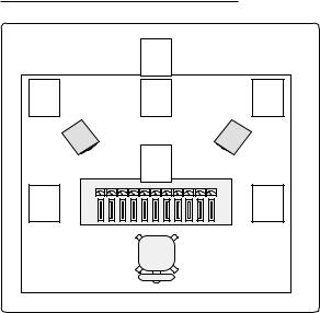
Figure 2. Subwoofer positioning
The figure to the left shows some example subwoofer positions within a room. Unless mentioned otherwise, the vents of the subwoofer should face towards the nearest wall.
1Recommended position.
2& 3 Recommended only when using two subwoofers.
4This arrangement may cause a loss in low frequencies if the distance from the listening position to the front wall is between 1 and 3m.
5The 'Soffit' or flush mount is also recommended. Here the vents must radiate into the room.
Positioning in the Room |
|
Safety Considerations |
|
Overload Indicators |
The placement of the subwoofer in the room will affect the overall frequency response of the system as, with low frequencies, the effects of the room are more apparent.
The subwoofer radiation ports should be placed within 1m of a wall. The amplifierpanelshouldnotbepositioned less than 10 cm from a surface, as this may cause heat dissipation problems from the amplifier back plate. The placement will affect the phase difference between the main monitors and the subwoofer, and also the bass roll-off rate. These effects can be compensated by the use of the controls in the amplifier unit; but consideration should be made when placing the subwoofer.
The 1094A/92A has been designed in accordance with international safety standards. However, to ensure safe operation and maintain the instrument under safe operating conditions the followingwarningsandcautionsshould be observed.
-Servicing and adjustment should only be performed by qualified service personnel.
-Opening the amplifier's rear panel is strictly prohibited except by such persons who are aware of the hazards involved.
-It is forbidden to use this product with an unearthed mains cable, which may lead to personal injury.
Warning!
Choose a central and symmetrical position for the subwoofer as this will give an even phase match between all monitor channels. Positioning the subwoofer close to a corner should be avoided as it will boost the bass level at lower frequencies and may cause asymmetrical spatial imaging.
See the section titled 'Subwoofer Positioning' for examples of recommended positions within a room.
This equipment is capable of delivering sound pressure levels in excess of 85dB, which may cause permanent hearing damage.
The 1094A contains a red 'Clip' LED. This indicator is located on the rear panel of the subwoofer.
The clip LED will light if the amplifier is overloaded. If this occurs frequently, reduce the input level to the subwoofer until the clip LED stops blinking.
 Loading...