


8320A
8330A
Operating Manual
8320A and 8330A Operating Manual
General Description
Genelec 8320A and 8330A are two-way smart active monitors designed for demanding professional applications.
Genelec Smart Active Monitor™ (SAM™) digital signal processing (DSP) built inside each smart active monitor with Genelec Loudspeaker Manager™ (GLM™) software provides unparalleled acoustic quality, ease of use, and high monitoring accuracy even in difficult acoustic environments. The high performance drivers are directly connected to dedicated D Class power amplifiers. System protection is implemented as a part of the SAM signal processing.
The MDE™ (Minimum Diffraction Enclosure™) enclosure is made of die-cast aluminium and shaped to reduce edge diffraction. Combined with the advanced Directivity Control WaveguideTM (DCWTM), this design contributes to the excellent acoustic neutrality.
Delivery Contents
Each monitor is supplied with a mains cable, 5 meter RJ45 cable, and an operating manual.
Connections
Before connecting, switch off the monitors and the signal source. Once all the connections have been made, the monitors can be switched on.
H
8320 146 mm 53/4 in
8330 190 mm 71/2 in
|
> |
,7 |
|
|
|
|
|
|
0 |
|
m |
H |
|
|
|
|
|
|
|
|
ACOUSTIC |
||
|
AXIS |
|
|
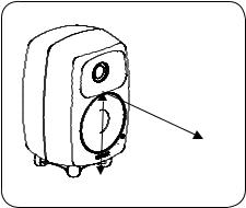
Figure 1: Location of the acoustic axis
Mains Power
The power switch is located on the back panel (see Figure 2). Connect the monitor to a mains socket having a protective earthed connection. Do not connect to an unearthed mains supply or using an unearthed mains cable. These monitors feature an universal mains voltage and can be connected to any voltage between 100-240 VAC 50-60 Hz.
GLM Network Connection
Up to 30 monitors and subwoofers can be connected to a computer using the GLM Adapter. An RJ45 cable is supplied for this. Start control network cabling from the GLM Adapter to the first monitor. Continue daisy-chaining to all monitors and subwoofers (see Figure 3). No special sequence is necessary.
2 English

GLM NETWORK CONNECTORS
292-8030W
POWER SWITCH
RESET TO FACTORY SETTINGS: PUSH BUTTON FOR 10 SEC
Figure 2: Control and connec- |
MAINS |
|
INPUT |
||
tor layout on the rear panel |
||
|
||
of an 8330A. The 8320A has |
|
|
an analog input only, and the |
|
|
GLM network connectors point |
|
|
downwards and are located |
|
|
next to the audio input. |
|
GLM NETWORK
|
8330A |
SMART ACTIVE MONITOR |
|
|
|
MAINS INPUT |
DIGITAL |
DIGITAL |
ANALOG |
||
50 / 60 Hz 60 W |
IN |
OUT |
|
IN |
|
100 - 240 V~ |
|
|
|
|
|
MAGNETICALLY SHIELDED |
|
1 |
2 |
2 |
1 |
MADE IN FINLAND |
www.genelec.com |
3 |
|
|
3 |
SERIAL NUMBER |
GND - |
+ |
+ |
- GND |
|
|
|
OUT |
|
IN |
|
SIGNAL CONNECTORS
-DIGITAL IN
-DIGITAL OUT
-ANALOG IN
GLM
NETWORK
GLM
NETWORK USB
MICROPHONE
Figure 3: GLM Network Adapter |
|
cabling. Audio cabling is not |
|
shown. |
LISTENING |
|
|
|
POSITION |
GLM NETWORK
Analog Audio Input
The analog audio input on both models accepts a balanced male XLR connector.
Digital Audio Input
The 8330A digital audio input (DIGITAL IN) accepts
a male XLR connector carrying an AES/EBU formatted digital audio signal. The digital audio can be routed to the next monitor or subwoofer using an XLR output (DIGITAL OUT). The AES/EBU digital audio subframe A or B is selected using the GLM software.
English 3
 Loading...