

Page 1
DEH–40053
g
ProTrip™ Trip Unit Target Module
ProTrip™ Conversion Kits
Introduction
ProTrip™ Trip Units are equipped with a Target Module.
This unit indicates whether a breaker trip was caused by a
short circuit, an overload, or a ground fault. The Target
Module is shown in Figure 1. The catalog number is
TARGET02P.
Note that the Target Modules do not provide the groundfault protection function. Ground-fault protection is
provided by the Rating Plug.
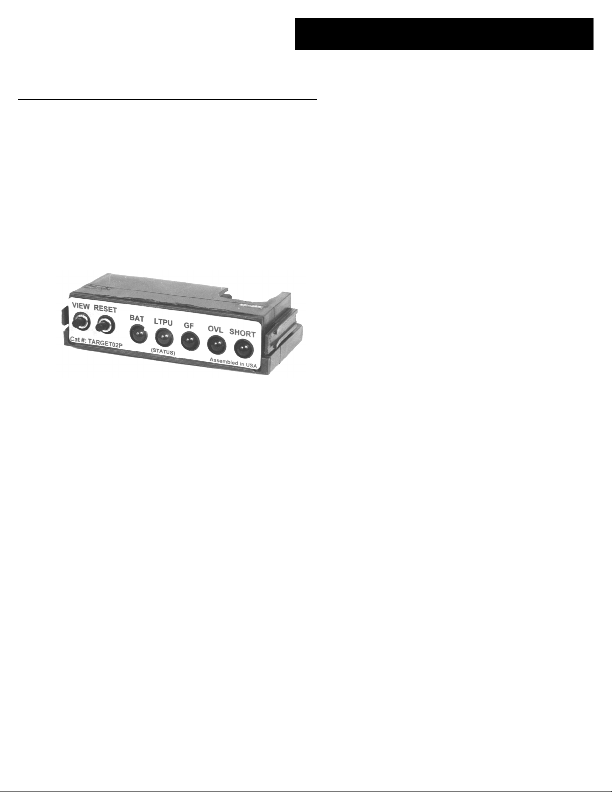
Figure 1. Power+ Target Module.
Functions
The front of the Target Module contains two push buttons
and five LEDs. The following functions are provided by
the Target Module.
Trip Targets
To determine the condition causing a breaker trip, press
the VIEW button. One of the three target LEDs will light, as
follows:
SC – Short circuit (instantaneous or short-time trip).
OVL – Overload (long-time trip).
GF – Ground.
The RESET button clears the trip target indication.
Battery Test
If the breaker has not tripped or if the trip target has been
cleared, pressing the VIEW button performs a battery test.
The BAT LED will light if the batteries are okay. If the BAT
LED is dim or does not light, replace the batteries as
described below. Note that the only function of the Target
Module batteries is to power the LEDs; they have no effect
on Trip Unit operation and are not required to store
targets for any protection functions.
Health Monitor
The Trip Unit can be tested for proper functioning if the
Trip Unit is powered by one of the following sources:
• A Test Kit (catalog number TVRMS2) is plugged
into the jack on the front of the Rating Plug.
• The breaker is carrying a load current of at least 20%
of its current sensor rating.
• External +24 Vdc control power, if connected.
Press and hold the VIEW button for at least five seconds. If
the Trip Unit is operating properly, the LTPU LED will
blink slowly. Note that if the Trip Unit is not powered by
one of the above sources, this test will not give a true
indication of Trip Unit functioning.
Installation
To install a Target Module in a ProTrip Trip Unit,
remove the existing module by following the removal
instructions below. Hold the Target Module between the
thumb and forefinger, then push it into the Trip Unit.
Proper engagement is verified by a click.
Long-Time Pickup Status
Whenever the circuit breaker is carrying at least 95% of
the long-time pickup current (C), the LTPU Status LED
begins to blink. Above 100% of the long-time pickup
current, the LED is lit continuously, indicating an
imminent overload trip.
Page 2
Removal
These instructions do not cover all details or variations in equipment nor do they provide for every possible contingency that
may be met in connection with installation, operation, or maintenance. Should further information be desired or should
particular problems arise that are not covered sufficiently for the purchaser’s purposes, the matter should be referred to the
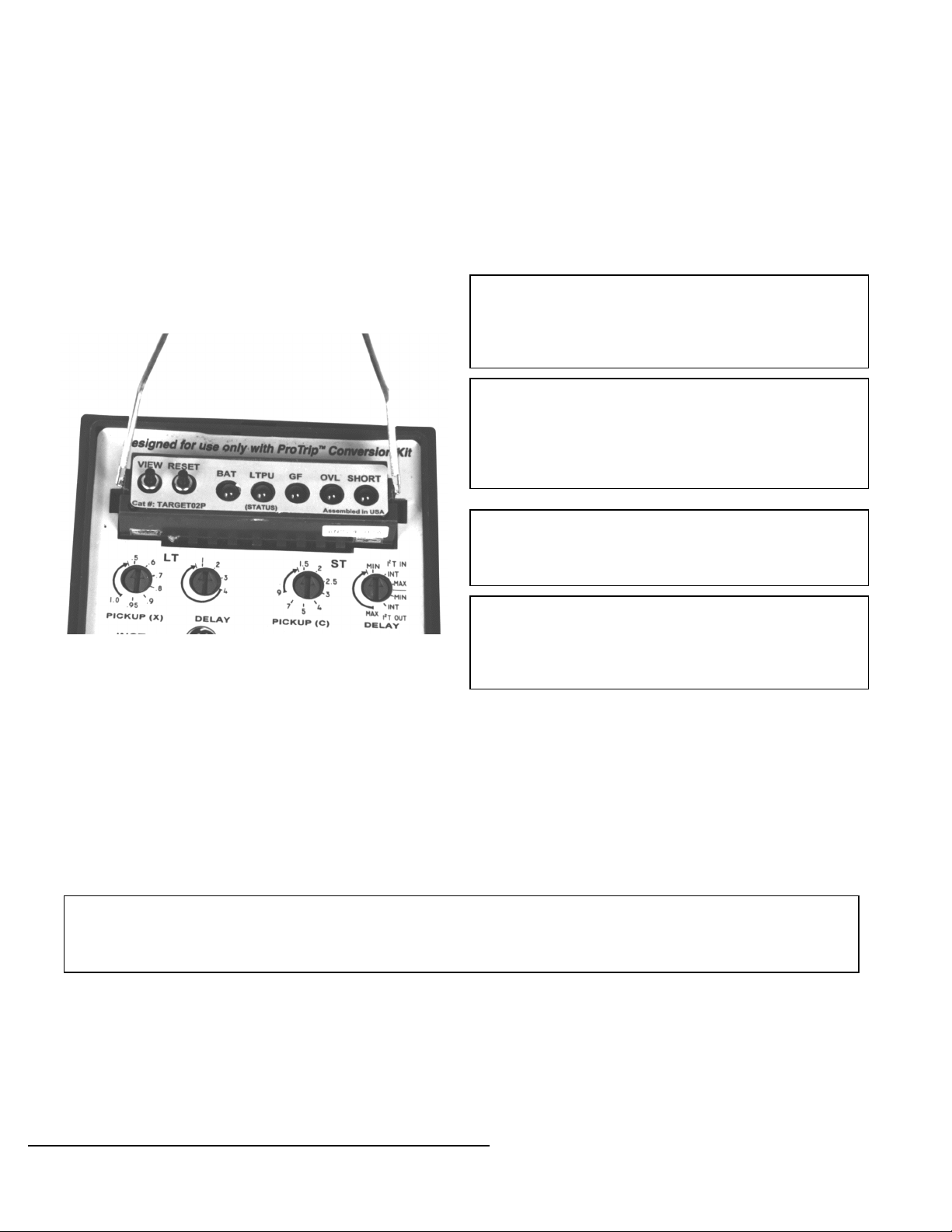
Battery Replacement
An installed Target Module is seated firmly in the Trip
Unit. As shown in Figure 1, there are tabs at the sides of
the Target Module for removal. A Rating Plug Removal
Tool, catalog number TRTOOL, also known as an
integrated circuit (DIP) extractor, is required to remove
the Target Module. Grasp the tabs of the module with the
tool, as shown in Figure 2. Be careful to hold the tabs and
not the front cover, as the Target Module could be
damaged otherwise. Gently pry the Target Module out by
pulling away from the Trip Unit. A gentle left-right
wriggling motion assists the removal. Insure that the tabs
are held securely until the Target Module is completely
removed.
To replace the two batteries in the Target Module, remove
the module from the Trip Unit as described above. Slide
the old batteries out from the battery compartment at the
rear of the Target Module. It may help to pry them out
with a small screwdriver blade in the cutout on top of the
module. Slide the new batteries into the battery
compartment. Be careful not to short out the batteries
during removal or installation. Recommended
replacement batteries are Panasonic CR1616, Eveready ECR1616BP, and Duracell DC1616B.
WARNING: Replace the batteries with Panasonic CR1616,
Eveready E-CR1616BP, or Duracell DC1616B only. Use
of a different battery may present risk of fire, explosion,
or damage to equipment. Observe proper battery polarity
when installing in the battery compartment.
AVERTISSEMENT: Remplacer la batterie avec
uniquement des Panasonic CR1616, Eveready ECR1616BP, ou Duracell DC1616B. L’utilisation d’autres
batteries peut présenter un risque de feu, d’explosion ou
d’endommagement du matériel. Respecter la polarité de
la batterie en l’installant dans son logement.
WARNING: The batteries may explode if mistreated. Do
not recharge, disassemble, or dispose of in fire. Keep the
battery away from children and dispose of the used
battery promptly.
GE Company.
Figure 2. Target Module removal.
AVERTISSEMENT: La batterie peut exploser en cas de
mauvaise utilisation. Ne pas la recharger, l’ouvrir ou la
jeter dans un feu. Doit être garder hors de portée des
enfants. Une fois usée, la batterie doit être jeté
rapidement.
g
GE Industrial Systems
General Electric Company
41 Woodford Ave., Plainville, CT 06062
DEH–40053 R01 1198 © 1998 General Electric Company
 Loading...