

Page 1
DEH–40034
g
ProTrip™ Trip Units
for Low-Voltage Power Circuit Breakers
User’s Guide
Page 2
ProTrip™ Trip Units
Getting Started
Since this Trip Unit is available in a variety of configurations, please take a moment to compare the catalog number of
your purchased Trip Unit with the catalog number key below.
Example
PKO50 D 3 F 16 08 R Code Description Function
PK###
PIK##
PD###
PSL##
GE AK Breaker
I-T-E® Breaker
Westinghouse® Breaker
Allis-Chalmers® Breaker
D ProTrip Trip Unit Trip Unit Model
3 3-Wire Breaker Wiring
Fixed Cts Sensor Type
F
01
150 A
02
225 A
06
600 A
08
800 A
16
1600 A
20
2000 A
32
3200 A
40
4000 A
Long-Time , Short-Time, Instantaneous,
08
Switchable Ground-Fault
R Replacement unit Ordered as Replacement
Breaker Family
Installed CT
Overcurrent Protection
Example – a Trip Unit with catalog number PKO50D3F1608R has the following features:
• GE AK-50 circuit breaker
• ProTrip Trip Unit
• 3-wire breaker
• Fixed CT sensors
• 1600 A CT installed
• Long-time, short-time, instantaneous, and switchable ground-fault overcurrent protection
• Trip Unit was ordered as a replacement
Page 3

WARNINGS
CAUTIONS
NOTES
DEH–40034
WARNINGS, CAUTIONS, AND NOTES
AS USED IN THIS PUBLICATION
Warning notices are used in this publication to emphasize that hazardous voltages, currents, or
other conditions that could cause personal injury or death are present in this equipment or may be
associated with its use.
Warning notices are also used for situations in which inattention or lack of equipment knowledge
could cause either personal injury or damage to equipment.
Caution notices are used for situations in which equipment might be damaged if care is not taken.
Notes call attention to information that is especially significant to understanding and operating the
equipment.
This document is based on information available at the time of its publication. While efforts have
been made to ensure accuracy, the information contained herein does not cover all details or
variations in hardware and software, nor does it provide for every possible contingency in
connection with installation, operation, and maintenance. Features may be described herein that
are not present in all hardware and software systems. GE Industrial Systems assumes no obligation
of notice to holders of this document with respect to changes subsequently made.
GE Industrial Systems makes no representation or warranty, expressed, implied, or statutory, with
respect to, and assumes no responsibility for the accuracy, completeness, sufficiency, or usefulness
of the information contained herein. No warrantees of merchantability or fitness for purpose shall
apply.
The following are trademarks of GE Company:
ProTrip™, MicroVersaTrip Plus™, MicroVersaTrip PM™
© 1998 GE Company
All Rights Reserved
i
Page 4

ProTrip™ Trip Units
Table of Contents
Chapter 1. Introduction
1–1 Applications............................................................................................................................................1
1–2 General...................................................................................................................................................1
1–3 Trip Unit Functions...............................................................................................................................1
1–4 Trip Unit Catalog Numbers...................................................................................................................2
1–5 Rating Plugs ...........................................................................................................................................3
Ground-Fault Protection.................................................................................................................4
1–6 Equipment Interfaces.............................................................................................................................4
1–7 Trip Unit Information...........................................................................................................................4
Trip Unit Label Information..........................................................................................................4
Selector Switches..............................................................................................................................4
Chapter 2. Trip Unit Setup
2–1 Overview .................................................................................................................................................5
2–2 Long-Time Pickup .................................................................................................................................5
2–3 Long-Time Delay ...................................................................................................................................5
2–4 Short-Time Pickup.................................................................................................................................6
2–5 Short-Time Delay...................................................................................................................................6
2–6 Instantaneous Pickup.............................................................................................................................6
2–7 Ground-Fault Pickup..............................................................................................................................7
2–8 Ground-Fault Delay................................................................................................................................7
2–9 Defeatable Ground Fault .......................................................................................................................7
Chapter 3. Trip Unit Status
3–1 Target Module .......................................................................................................................................8
3–2 Functions................................................................................................................................................8
Trip Targets.....................................................................................................................................8
Long-Time Pickup Status................................................................................................................8
Battery Test......................................................................................................................................8
Health Monitor................................................................................................................................8
Chapter 4. Maintenance and Trouble-Shooting
4–1 Trip Unit Removal and Replacement...................................................................................................9
4–2 Rating Plug Removal and Replacement...............................................................................................9
4–3 Target Module Removal and Replacement..........................................................................................9
Target Module Battery Replacement ...........................................................................................10
4–4 High-Current Testing..........................................................................................................................10
4–4 Trouble-Shooting Guide......................................................................................................................11
ii
Page 5

ProTrip™ Trip Units
List of Figures
1. Front view of the ProTrip Trip Unit.........................................................................................................1
2. ProTrip rating plug................................................................................................................................... 3
3. Time-current curve illustrating long-time pickup.................................................................................... 5
4. Time-current curve illustrating long-time delay.......................................................................................5
5. Time-current curves illustrating short-time pickup.................................................................................. 6
6. Time current curve illustrating short-time delay with I2T OUT.............................................................6
7. Time current curve illustrating short-time delay with I2T IN..................................................................6
8. Time-current curve illustrating instantaneous pickup............................................................................. 6
9. Time-current curve illustrating ground-fault pickup...............................................................................7
10. Time-current curve illustrating ground-fault delay with I2T OUT.........................................................7
11. Time-current curve illustrating ground-fault delay with I2T IN..............................................................7
12. Target module........................................................................................................................................... 8
13. Removing the interchangeable rating plug. ............................................................................................9
14. Removing the target module. .................................................................................................................10
iii
Page 6

ProTrip™ Trip Units
List of Tables
1. Breaker type referred to by the first character of the Trip Unit catalog number.................................... 2
2. Trip Unit type referred to by the sixth character of the Trip Unit catalog number............................... 2
3. Wiring type referred to by the seventh character of the Trip Unit catalog number............................... 2
4. Sensor type referred to by the eighth character of the Trip Unit catalog number................................. 2
5. Installed CT, as indicated by the ninth and tenth characters of the Trip Unit catalog number .......... 2
6. Trip unit functions, as indicated by the eleventh and twelfth characters of the Trip Unit catalog
number. ..................................................................................................................................................... 3
7. Catalog numbers for rating plugs............................................................................................................. 3
8. Summary of protective functions and setting values for each. ................................................................ 5
9. Nominal delays for the long-time delay bands......................................................................................... 5
10. Settings available for ground-fault pickup according to breaker frame size........................................... 7
iv
Page 7

ProTrip™ Trip Units
Chapter 1. Introduction
1–1 Applications
The ProTrip™ Trip Units described in this publication
are used on GE; I-T-E® and ABB®; Allis Chalmers®,
Siemens/Allis®, and Siemens®; and Westinghouse and
Cutler-Hammer® low-voltage power circuit breakers.
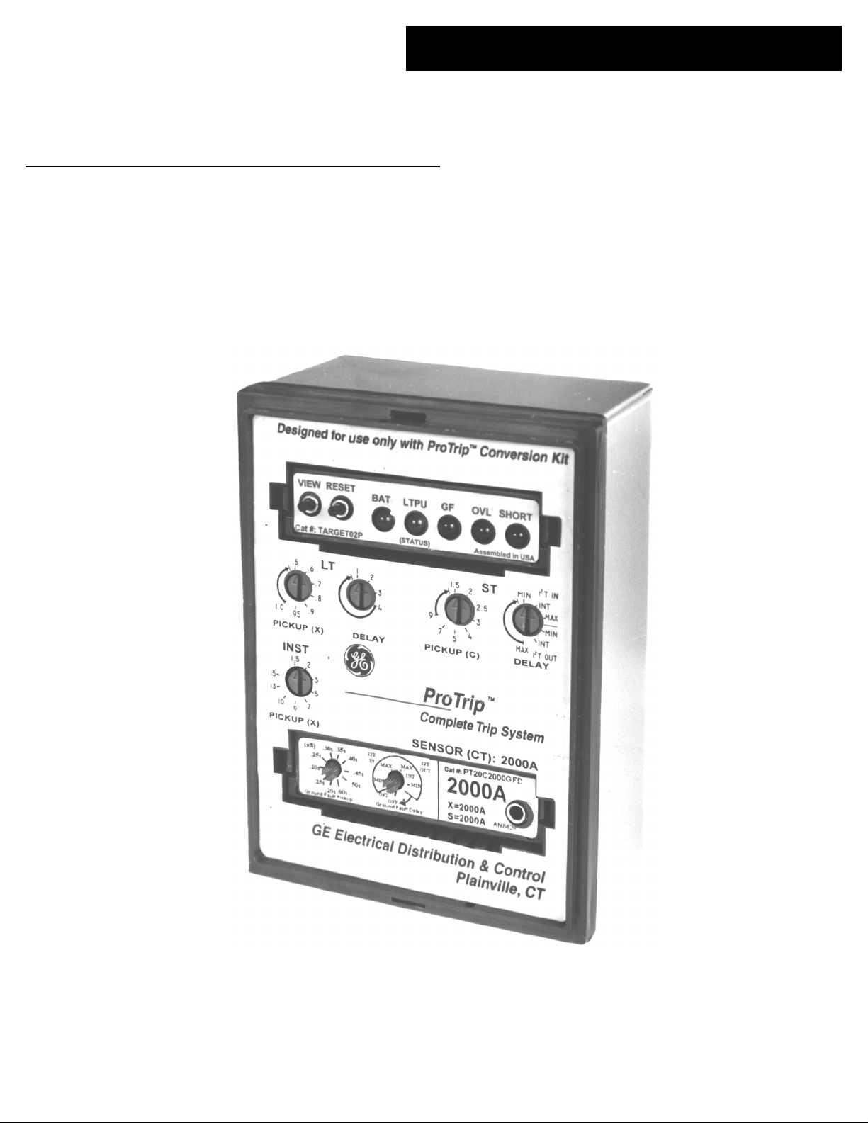
Figure 1 shows the ProTrip Trip Unit.
ProTrip Trip Units are removable from the circuit
breaker. For instructions on installing and removing the
Trip Unit, see Chapter 4.
CAUTION: Removal of a Trip Unit from its breaker must
be performed with the breaker in the OPEN or TRIPPED
position. Draw-out breakers should be racked out first.
ATTENTION: Pour retirer déclencheur, le disjoncteur
doit être en position ouverte ou déclenchée. Les
disjoncteurs débrochables doivent ètre en position
débrochée.
CAUTION: Do not attempt to operate the breaker without
its assigned Trip Unit. Installation of an incorrect Trip
Unit may result in unsafe operation of the breaker.
ATTENTION: Ne pas utiliser le disjoncteur sans son
déclencheur. Une mauvaise installation du déclencheur
peut être dangereuse.
NOTE: Trip Units as received may have settings that are
undesirable for the specific application. Ensure that
settings are appropriately adjusted before energizing.
Figure 1. Front view of the ProTrip Trip Unit.
1–2 General
ProTrip Trip Units are the same size and have the same
50-pin male D-sub connector as the RMS9D series of
MicroVersaTrip Plus™ and MicroVersaTrip PM™ Trip
Units.
ProTrip Trip Units may be tested with the Trip Unit
installed in the circuit breaker, the rating plug installed in
the Trip Unit, and the breaker carrying current. The Test
Kit plugs into the test socket of the rating plug. The Test
Kit catalog number is TVRMS2 and its operation is
described in GEK–97367.
NOTE: Les disjoncteurs sont livrés avec des réglages
standards qui peuvent être inadéquates pour certaines
applications. Vérifier ces réglages avant de mettre le
disjoncteur sous tension.
1–3 Trip Unit Functions
ProTrip Trip Units have specific standard functions, with
the current rating determined by installation of the rating
plug. The functions of the Trip Unit are as follows:
• Overcurrent protection
– Long-time protection
– Instantaneous protection
• Protection
– Short-time protection, with or without I2T
– Ground-fault protection, with or without I2T
• Status
– Trip targets
– Health monitor
1
Page 8

ProTrip™ Trip Units
Chapter 1. Introduction
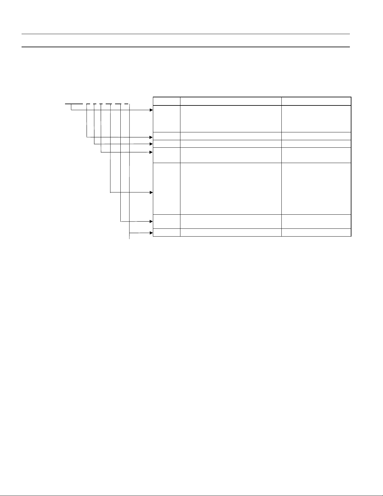
1–4 Trip Unit Catalog Numbers
A simple catalog-numbering system defines all of the
standard and optional Trip Unit functions. A catalog
numbering key is found inside the front cover (but see
Table 1 for the complete list of supported breakers). Each
of the segments of the catalog number is described below.
The first five-character group indicates the breaker type
for which the Trip Unit is configured, as listed in Table 1.
Character Trip Unit Type
D ProTrip
Table 2. Trip Unit type referred to by the sixth character of the
Trip Unit catalog number.
The seventh character of the catalog number indicates the
wiring type of the breaker, as listed in Table 3.
Characters Breaker Type
GE
PK115
PKO15
PK125
PKO25
PK150
PKO50
PKO75
PKO10
PKW10
AK-1-15
AK-15
AK-1-25
AK-25, AKU-25
AK-1-50
AK-50, AKU-50, AKT-50, AKS-50, AKSU-50, AKST-
50
AK-75
AK-100
AKW10
I-T-E®, ABB®
PIK22
PIK60
PIKC8
PIK80
PIK1B
PIK16
PIKN1
K-225
K-600, KDON-600
KC (800 A)
K-800, KDON-800
K-1600 (black), KDON-1600 (black)
K-1600 (red) KDON-1600 (red, rect. primary
disconnects)
KDON-1600 (red, circ. primary disconnects)
Westinghouse®, Cutler-Hammer®
PDB15
PDB25
PDA50
PDB50
PDA75
PDB75
PDA10
PDB10
DB-15, DBL-15
DB-25, DBL-25
DA-50
DB-50, DBL-50
DA-75
DB-75
DA-100
DB-100
Allis/Chalmers®, Siemens/Allis®, Siemens
PSL6B
PSL6G
PSL1B
PSL1G
LA-600 (blue), LAF-600 (blue)
LA-600 (gold), LAF-600 (blue)
LA-1600 (blue), LAF-1600 (blue)
LA-1600 (gold), LAF-1600 (gold)
Table 1. Breaker type referred to by the first five characters of the
Trip Unit catalog number.
The sixth character of the catalog number is always the
letter D, indicating the Trip Unit type, as shown in Table
2.
Character Wiring Type
3 3 Wire
Table 3. Wiring type referred to by the seventh character of the
Trip Unit catalog number.
The eighth character of the catalog number indicates the
sensor type, as listed in Table 4, and is always an F, for
fixed CTs.
Character Sensor Type
F Fixed CTs
Table 4. Sensor type referred to by the eighth character of the
Trip Unit catalog number.
The ninth and tenth characters of the catalog number
indicate the CT that is installed in the circuit breaker, as
listed in Table 5.
Characters Installed CT
01 150 A
02 225 A
06 600 A
08 800 A
16 1600 A
20 2000 A
30 3000 A
32 3200 A
40 4000 A
Table 5. Installed CT, as indicated by the ninth and tenth
characters of the Trip Unit catalog number.
The eleventh and twelfth characters of the catalog
number indicate the trip functions provided by the Trip
Unit, as listed in Table 6.
2
Page 9

ProTrip™ Trip Units
Chapter 1. Introduction
Characters Protective Function
08
Long-time, short-time, instantaneous, and
switchable ground fault
Table 6. Trip unit functions, as indicated by the eleventh and
twelfth characters of the Trip Unit catalog number.
Finally, if the Trip Unit was ordered as a replacement, the
letter R is appended to the catalog number.
For example, a Trip Unit with catalog number
PK050P3F1608R has the following functions:
PK050 – Trip Unit for AK-50 circuit breaker with a
frame rating of 1600 A
D – ProTrip Trip Unit
3 – 3-wire configuration
F – Fixed CT sensors
16 – 1600 A sensors
08 – Long-time, short-time, instantaneous, and
switchable ground fault protection functions
R – Trip Unit was ordered as a replacement
1–5 Rating Plugs
Interchangeable rating plugs are used to establish or
change the trip rating of the breaker. A built-in rejection
feature prevents the insertion of a rating plug with an
incorrect sensor rating into a Trip Unit. Rating plug
catalog numbers are listed in Table 7. A rating plug is
shown in Figure 2.
Figure 2. ProTrip rating plug.
CAUTION: Removal of the rating plug while the breaker
is carrying current reduces the breaker’s current-carrying
capacity to approximately 25% of the current sensor
rating. This may result in undesired tripping.
ATTENTION: Si le calibreur est retiré alors que le
disjoncteur est sous tension, le déclencheur se régle
automatiquement à approximativement 25% du calibre
du transformateur de courant. Ceci peut entrainer un
déclenchement indésirable.
Cat. No.
PT1C80GFD 80
PT1C100 GFD 150 100
PT1C125 GFD 125
PT1C150 GFD 150
PT225C150 GFD 225 150
PT225C225 GFD 225
PT4C200GFD 200
PT4C225GFD 225
PT4C250GFD 400 250
PT4C300GFD 300
PT4C400GFD 400
PT6C300GFD 300
PT6C400GFD 400
PT6C450GFD 600 450
PT6C500GFD 500
PT6C600GFD 600
PT8C400GFD 400
PT8C450GFD 450
PT8C500GFD 800 500
PT8C600GFD 600
PT8C700GFD 700
PT8C800GFD 800
PT16C800GFD 800
PT16C1000GFD 1000
PT16C1100GFD 1600 1100
PT16C1200GFD 1200
PT16C1600GFD 1600
PT20C1000GFD 1000
PT20C1200GFD 1200
PT20C1500GFD 2000 1500
PT20C1600GFD 1600
PT20C2000GFD 2000
PT30C1200GFD 1200
PT30C1600GFD 1600
PT30C2000GFD 3000 2000
PT30C2500GFD 2500
PT30C3000GFD 3000
PT32C1200GFD 1200
PT32C1600GFD 3200 1600
PT32C2400GFD 2400
PT32C3200GFD 3200
PT40C1600GFD 1600
PT40C2000GFD 2000
PT40C2500GFD 4000 2500
PT40C3000GFD 3000
PT40C3600GFD 3600
PT40C4000GFD 4000
Sensor
Rating, A
Table 7. Catalog numbers for rating plugs.
Plug Rating,
A
3
Page 10

ProTrip™ Trip Units
Chapter 1. Introduction
Ground-Fault Protection
Ground-fault protection with ProTrip Trip Units is provided in the rating plug. The pickup and delay settings
available with the switches on the rating plug are
described in Chapter 2, Trip Unit Setup.
1–6 Equipment Interfaces
ProTrip Trip Units do not usually require connections
within the equipment, since all wiring is contained within
the circuit breaker. The only connection is for the neutral
sensor, which uses a special dedicated disconnect.
CAUTION: Neutral current sensors are required for
single-phase, three-wire and three-phase, four-wire
systems. When the Trip Unit is connected to a threephase, three-wire system, the neutral sensor terminals of
the breaker are left open. Do not short any neutral
current sensor terminals in a three-phase, three-wire
system, as this could result in damage to, or malfunction
of, the electrical system.
ATTENTION: Un transformateur de courant de neutre
est nécessaire pour les réseaux 3 phases + neutre. Si le
neutre n’est pas distribué, les bornes de neutre du
déclencheur doivent être laissées ouvertes. Ne pas les
court-circuiter (ceci peut endommager le déclencheur et
entrainer un mauvais fonctionnement du système
électrique.
1–7 Trip Unit Information
Trip Unit Label Information
Following are descriptions of the various numbers on the
front of the Trip Unit, as shown in Figure 1.
• Top-left corner – Serial number of the Trip Unit, such
as RMS71234567.
• Top-right corner – Date of manufacture code, such as
P1121=.
• Right center above rating plug – Catalog number of the
Trip Unit, such as PK050D3F1608R.
• Right center, below catalog number – Current sensor
rating in amperes.
There are two more labels on the Trip Unit that are not
generally visible when it is plugged into a breaker.
• Side of unit – Bar code giving the catalog number of
the Trip Unit.
• Rear of unit – Yellow caution label.
Selector Switches
The following selector switches are present on the front of
the Trip Unit. See Chapter 2, Setup Mode, for a complete
description of each function.
• Long-time pickup
• Long-time delay
• Short-time pickup
• Short-time delay
• Instantaneous pickup
• Ground-fault pickup (on the rating plug)
• Ground-fault delay (on the rating plug)
4
Page 11

2–1 Overview
All of the Trip Unit protective functions are set with the
rotary selector switches on the front of the unit. Table 8
contains a summary of the functions and the available
settings.
Most of the selector switch scales (all but instantaneous
pickup) have a heavy curved line, with an arrowhead on
one end, connecting the low and high ends of the scale.
When the switch points anywhere within this region, the
highest value at the end of the line opposite the
arrowhead is the active setting.
ProTrip™ Trip Units
Chapter 2. Trip Unit Setup
2–2 Long-Time Pickup
The long-time pickup set point establishes the breaker’s
nominal ampere rating, C, as a fraction of the rating plug
current, X. The choices for C are .5, .6, .7, .8, .9, .95, 1.0,
and 1.1 times X. Figure 3 illustrates the long-time pickup
settings.
2–3 Long-Time Delay
The long-time delay function allows normal momentary
overloads without nuisance tripping. The nominal time
delays at the lower limits of the bands for 600% of the
long-time current set point, C, for the four selectable
bands are listed in Table 9. Figure 4 illustrates the effect of
this delay on the trip time.
Figure 3. Time-current curve illustrating long-time pickup.
Figure 4. Time-current curve illustrating long-time delay.
Band Delay, sec
1 2.4
2 4.9
3 9.8
4 20
Table 9. Nominal delays for the long-time delay bands.
Parameter Pickup Settings Delay Settings Delay Curve
Long-Time Trip .5, .6, .7, .8, .9, .95, 1.0, 1.1
multiple of Rating Plug Current (X)
Short-Time Trip 1.5, 2, 2.5, 3, 4, 5, 7, 9
multiple of Long-Time setting (C)
Instantaneous Trip 1.5, 2, 3, 5, 7, 9, 101, 131, 15
multiple of Rating Plug Current (X)
Ground-Fault Trip .2, .25, .3, .35, .4, .45, .5, .6
1
Maximum setting is limited by the frame size.
2
Maximum setting is limited to 1200 A. Pickup settings are determined by the breaker frame size
Table 8. Summary of protective functions and setting values for each.
multiple of Sensor rating (S)
1
2
2.4, 4.9, 9.8, 20 seconds
(Bands 1, 2, 3, 4)
.10, .21, .35 second
(Min, Int, Max)
No delay N/A
.10, .21, .35 seconds
(Min, Int, Max)
I2T In, I2T Out
I2T In, I2T Out
5
Fixed
Page 12

ProTrip™ Trip Units
Chapter 2. Trip Unit Setup
2–4 Short-Time Pickup
The short-time pickup function establishes the current at
which short-time trip is activated. Short-time pickup is
coupled with long-time pickup and the choices of pickup
settings are 1.5, 2, 2.5, 3, 4, 5, 7, and 9 times the long-time
setting. The time-current curves for short-time pickup is
illustrated in Figure 5.
Figure 6. Time current curve illustrating short-time delay with I2T
OUT.
Figure 5. Time-current curves illustrating short-time pickup.
2–5 Short-Time Delay
This function delays the breaker trip when the short-time
pickup function is activated. The switch settings MIN, INT,
and MAX correspond to nominal time delays of .10, .21,
and .35 second, respectively. The delay with I
2
T IN is for a
current of 600% of C at the lower limit of the band. The
delay with I
The I
constant time delay. I
2
T OUT is for the lower limit of each band.
2
T OUT function, illustrated in Figure 6, establishes a
2
T IN biases the delay with a constant
slope, as shown in Figure 7.
2–6 Instantaneous Pickup
Instantaneous overcurrent protection causes an immediate breaker trip when the chosen current setting is
reached. The pickup current may be set to 1.5, 2, 3, 5, 7,
and 9 times the rating plug current, X. Additional settings
of 10, 13, and 15 times X are also available, depending on
the breaker frame size.
Note the difference from short-time pickup, which is based
on a multiple of the long-time pickup setting, C, while
instantaneous pickup is based on the rating plug current,
X. The time-current characteristic is illustrated in Figure 8.
Figure 7. Time current curve illustrating short-time delay with I2T
IN.
Figure 8. Time-current curve illustrating instantaneous pickup.
6
Page 13

2–7 Ground-Fault Pickup
This function sets the pickup current for ground-fault
protection. The available settings are listed in Table 10 as
multiples of X, the current sensor rating. The maximum
setting may be less than 0.6, depending on the breaker
frame size. Figure 9 illustrates the time-current curve for
ground-fault pickup.
Breaker Frame Settings as Multiple of X
800–2000 A .20, .25, .30, .35, .40, .45, .50, .60
3200 A .20, .22, .24, .26, .28, .30, .34, .37
4000–5000 A 20, .22, .24, .26, .28, .30
Table 10. Settings available for ground-fault pickup according to
breaker frame size.
ProTrip™ Trip Units
Chapter 2. Trip Unit Setup
Figure 10. Time-current curve illustrating ground-fault delay with
I2T OUT.
Figure 9. Time-current curve illustrating ground-fault pickup.
2–8 Ground-Fault Delay
This function sets the delay before the breaker trips when
the ground-fault pickup current is detected. The switch
settings MIN, INT, and MAX correspond to nominal time
delays of .10, .21, and .35 second, respectively. The delay
2
with I
T OUT is for the lower limit of each band. The delay
2
with I
T IN is at 200% of the pickup setting at the lower
limit of the band.
2
The I
T OUT function, illustrated in Figure 10, establishes
a constant time delay. I
constant slope, as shown in Figure 11.
2
T IN biases the delay with a
Figure 11. Time-current curve illustrating ground-fault delay with
I2T IN.
2–9 Defeatable Ground Fault
All rating plugs have the additional setting OFF on the
Pickup switch, which defeats ground-fault protection.
These rating plugs are not UL listed.
7
Page 14

ProTrip™ Trip Units
Chapter 3. Trip Unit Status
3–1 Target Module
Trip Unit status information is provided by the target
module, shown in Figure 12. This module indicates
whether a breaker trip was caused by a short circuit, an
overload, or a ground fault, as well as whether the Trip
Unit is functioning properly. The catalog number of the
target module is TARGET02P.
Figure 12. Target module.
3–2 Functions
The front of the target module contains two push buttons
and either four or five LEDs. The following functions are
provided by the target module.
operation and are not required to store targets or for any
protection functions.
Health Monitor
The Trip Unit can be tested for proper functioning if the
Trip Unit is powered by one of the following sources:
• A Test Kit (catalog number TVRMS2) is plugged
into the jack on the front of the rating plug.
• A Portable Battery Pack (catalog number TVPBP) is
plugged into the jack on the front of the rating plug.
• The breaker is carrying a load current of at least 20%
of its current sensor rating.
• External +24 Vdc control power is connected.
Press and hold the VIEW button for at least five seconds. If
the Trip Unit is operating properly, the LTPU LED will
blink slowly. Note that if the Trip Unit is not powered by
one of the above sources, this test will not give a true
indication of Trip Unit functioning.
Trip Targets
To determine the condition causing a breaker trip, press
the VIEW button. One of the three target LEDs will light,
as follows:
SC – Short circuit (instantaneous or short-time trip)
OVL – Overload (long-time trip)
GF – Ground fault
The RESET button clears the trip target indication.
Long-Time Pickup Status
Whenever the circuit breaker is carrying at least 95% of
the long-time pickup current (C), the LTPU (STATUS)
LED begins to blink. Above 100% of the long-time pickup
current, the LED is lit continuously, indicating an
imminent overload trip.
Battery Test
If the breaker has not tripped or if the trip target has been
cleared, pressing the VIEW button performs a battery test.
The BAT LED will light if the batteries are okay. If the BAT
LED is dim or does not light, replace the batteries as
described in Chapter 4, Maintenance and Trouble-Shooting.
Note that the only function of the Target Module batteries
is to power the LEDs; they have no effect on Trip Unit
8
Page 15

4–1 Trip Unit Removal and Replacement
Rejection pins are installed on the rear of all Trip Units to
prevent installation of an incorrect Trip Unit into a
breaker. Do not use excessive force when installing a Trip
Unit.
To install the Trip Unit, perform the following procedure:
1. Unscrew the brass knob in the center of the rear of
the trip unit. Lineup the mounting bracket to engage
the rejection posts. Screw the brass knob through the
bracket and into the trip unit.
2. Plug the wiring harness into the trip unit and screw it
to the bracket.
3. Attach the mounting bracket to the adapter plate,
previously installed on the breaker.
4–2 Rating Plug Removal and Replacement
CAUTION: Removal of the rating plug while the breaker
is carrying current reduces the breaker’s current-carrying
capacity to approximately 25% of the current sensor
rating.
ATTENTION: Si le calibreur est retiré le disjoncteur et
traversé par un courant, le niveau de protection s’ajuste à
approximativement 25% du calibre du transformateur
d’intensité.
Interchangeable rating plugs are removed with a rating
plug removal tool, Catalog No. TRTOOL. (Suitable
equivalents are commercially available as “integrated
circuit (DIP) extractors.”) Grasp the rating plug tabs with
the extractor and pull the plug out as illustrated in Figure
13. Be sure to grab the tabs and not the front cover of the
rating plug, or the plug may be damaged.
ProTrip™ Trip Units
Chapter 4. Maintenance and Trouble-Shooting
Figure 13. Removing the interchangeable rating plug.
4–3 Target Module Removal and Replacement
The target module is removed with the rating plug
removal tool, catalog number TRTOOL, also known as an
integrated circuit (DIP) extractor. Grasp the tabs of the
module with the tool, as shown in Figure 14. Be careful to
hold the tabs and not the front cover, as the Target
Module could be damaged otherwise. Gently pull the
Target Module away from the Trip Unit. A gentle leftright motion assists the removal. Insure that the tabs are
held securely until the Target Module is completely
removed.
To install a target module, hold the module between the
thumb and forefinger, then push it into the Trip Unit.
Proper engagement is verified by a click.
To install a rating plug, hold the plug between the thumb
and forefinger, then push it into the Trip Unit. Proper
engagement is verified by a click. Rejection features are
provided on all rating plugs to prevent application
mismatches. Never force a rating plug into place. Refer to
Chapter 1 to find the appropriate rating plugs for each
sensor rating and breaker frame.
Do not attempt to use a rating plug from a different type
of Trip Unit in a ProTrip Trip Unit.
9
Page 16

ProTrip™ Trip Units
Chapter 4. Maintenance and Trouble-Shooting
Figure 14. Removing the target module.
AVERTISSEMENT: La batterie peut exploser en cas de
mauvaise utilisation. Ne pas la recharger, l’ouvrir ou la
jeter dans un feu. Doit être garder hors de portée des
enfants. Une fois usée, la batterie doit être jeté
rapidement.
4–4 High-Current Testing
The TVRMS2 Test Kit does not defeat ground fault on the
ProTrip Trip Unit. If the breaker equipped with a ProTrip
Trip Unit is undergoing high-current testing, then two
poles must be connected in series to prevent ground fault
operation.
Target Module Battery Replacement
To replace the two batteries in the Target Module, remove
the module from the Trip Unit as described above. Slide
the old batteries out from the battery compartment at the
rear of the Target Module. It may help to carefully pry
them out with a small screwdriver blade in the cutout on
top of the module. Slide the new batteries into the battery
compartment. Be careful not to short out the batteries
during removal or installation. Recommended
replacement batteries are Panasonic CR1616, Eveready ECR1616BP, and Duracell DC1616B.
WARNING: Replace the batteries with Panasonic
CR1616, Eveready E-CR1616BP, or Duracell DC1616B
only. Use of a different battery may present risk of fire,
explosion, or damage to equipment. Observe proper
battery polarity when installing in the battery
compartment.
AVERTISSEMENT: Remplacer la batterie avec
uniquement des Panasonic CR1616, Eveready ECR1616BP, ou Duracell DC1616B. L’utilisation d’autres
batteries peut présenter un risque de feu, d’explosion ou
d’endommagement du matériel. Respecter la polarité de
la batterie en l’installant dans son logement.
WARNING: The batteries may explode if mistreated. Do
not recharge, disassemble, or dispose of in fire. Keep the
battery away from children and dispose of the used
battery promptly.
10
Page 17

Chapter 4. Maintenance and Trouble-Shooting
4–4 Trouble-Shooting Guide
The following guide is provided for trouble-shooting and
isolating common problems. It does not cover every
possible condition. Contact the Customer Support Center
at 800-843-3742 if the problem is not resolved by these
procedures.
Symptom Possible Cause Corrective Action
1. The health monitor
function of the target
module does not
operate.
Line current is below 20% of
the breaker sensor rating.
The target module is not
seated properly.
At least 20% of the current sensor rating, X, must be
flowing through the breaker to activate this function.
If the load current is below this level, power the Trip
Unit with the Test Kit or the Portable Battery Pack.
Verify that the target module is fully seated in its slot.
ProTrip™ Trip Units
2. The trip indication
target will not clear.
3. The battery check
(BAT) LED on the
target module does not
light.
4. The circuit breaker trips
at too low a current.
The target module batteries
are low.
The target module batteries
are low.
The rating plug is not fully
seated.
An incorrect rating plug is
installed.
Replace the batteries in the target module.
Replace the batteries in the target module
Verify that the rating plug is fully seated in its slot.
Check the current rating and catalog number of the
rating plug.
11
Page 18

g
GE Industrial Systems
General Electric Company
41 Woodford Avenue, Plainville, CT 06062
DEH40034 R01 1098 © 1998 General Electric Company
 Loading...