

Page 1

GE Energy
Programmer
Disconnect
Accessory Manual for Retrofil CB
Programmer secondary disconnects are not provided on AKD5 legacy LVS breakers.
If the customer has chosen to utilize the advanced features of the EntelliGuard ACB,
the control wiring need to routed from the LVS directly to the secondary disconnect
landing points on the cassette assembly of the EntelliGuard ACB cassette.
imagination at work
Page 2

Table of Contents
Related Publications ..................................................................................................................................................................2
Estimated Time to Complete Tasks ......................................................................................................................................... 2
General Description ...................................................................................................................................................................2
AKD-5—Programmer Secondary Disconnect (Breaker Side—N/A) ....................................................................................4
AKD-6—19-Pin Programmer Disconnect Overview .............................................................................................................. 4
AKD-6—Programmer Secondary Disconnect (Breaker Side) ............................................................................................... 4
AKD-6—Programmer Secondary Disconnect (Compartment Side) ...................................................................................5
AKD-8—Programmer Secondary Disconnect ........................................................................................................................8
Description ........................................................................................................................................................................................................................................... 9
Identify Existing Programmer Disconnect (Compartment) ............................................................................................................................................ 9
Identify Programmer Disconnect Type to be Installed (with Kit) ................................................................................................................................. 9
Remove Existing Programmer Disconnect (Compartment) ..........................................................................................................................................9
Install 19-Pin Programmer Disconnect (Compartment and Breaker) .................................................................................................................... 10
Wiring and Task Completed ...................................................................................................................................................................................................... 11
Wiring Diagram for the AK/AKR Retrofill .............................................................................................................................12
Notes ..........................................................................................................................................................................................13
Programmer Disconnect — Accessory Manual for Retrofil CB
1
DEH-41532 02/12
Page 3
Related Publications
Publication Publication Number
Brochure DEA-532
Snapshot DEE-543
Installation Manual AKD8 DEH-41549
Installation Manual AKD6 DEH-41548
Installation Manual AKD5 DEH-41547
Accessory: Door Interlock (Door Interlock Kit) DEH-41529
Accessory Retrofill Doors Assembly DEH-41563
Accessory: Position Switch Plate & Position Switch
Assembly & Wiring (Position Switch Kit)
Accessory: Neutral Rogowski CT Disconnect
(Neutral Assemblies)
Accessory: Programmer Disconnects DEH-41532
Accessory: Finger Clusters (Cluster Assemblies) DEH-41533
Accessory: Secondary Disconnects DEH-41534
FAQ DEQ-171
Application Guide DET-753
Guideform Spec DET-754
Spare/Renewal Parts Guide DET-755
DEH-41530
DEH-41531
Estimated Time to Complete Tasks
It takes about 20 minutes to install the assembly.
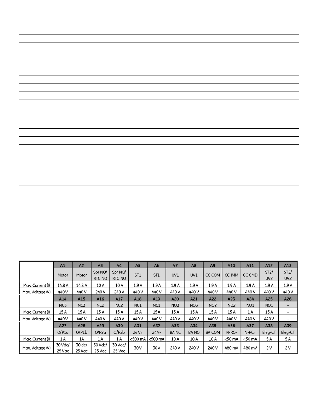
General Description
Description of the landing points on the EntelliGuard ACB secondary disconnect blocks given below. A-block is
featured in Figure 1 and B-block is featured in Figure 2.
Figure 1. EntelliGuard G 39-Point Secondary A-Block
DEH-41532 02/12
Programmer Disconnect — Accessory Manual for Retrofil CB
2
Page 4
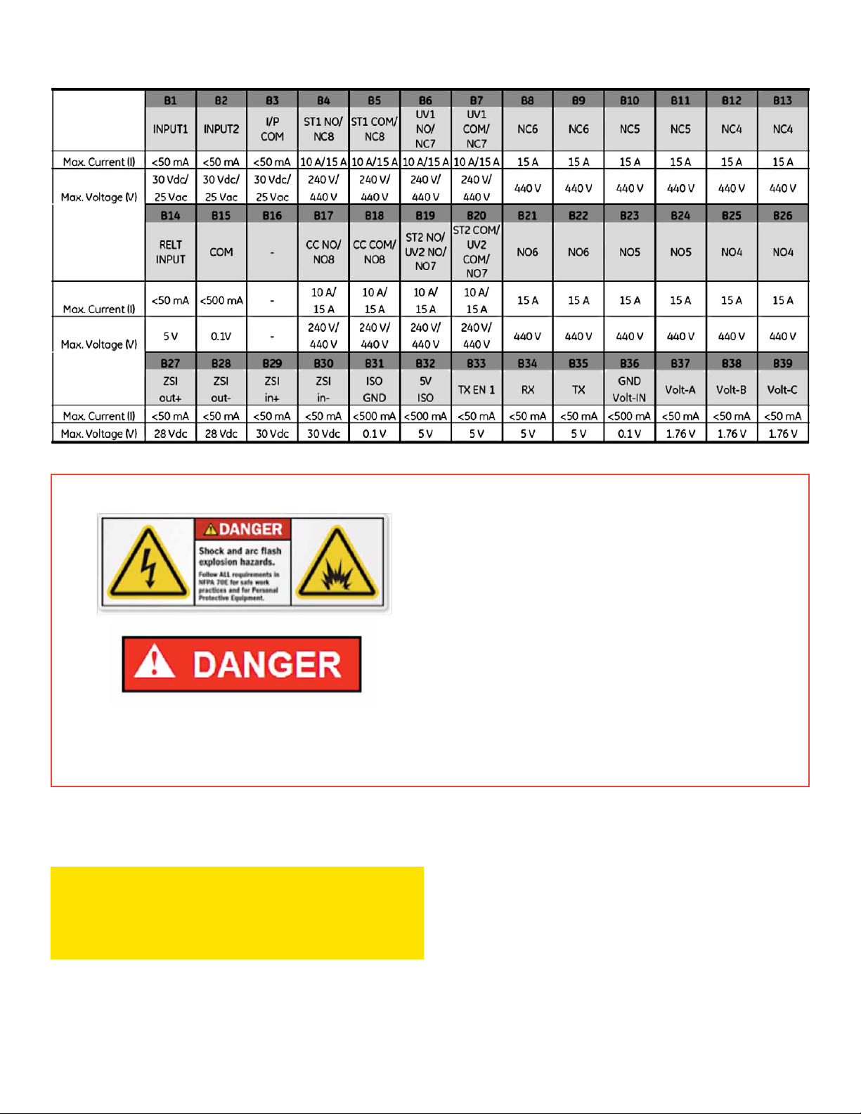
Figure 2. EntelliGuard G 39-Point Secondary B-Block
• Turn off all power to switchgear. Tagout
and lockout main source, up-stream or
main breaker.
• Failure to comply with these instructions
will result in death or serious injury from
severe burns caused by arc flashing that
has exceedingly high temperatures.
• Always wear personal protection equipment
according to OSHA standards and appropriate
to the severity of potential burns.
• Ensure only qualified personnel install, operate, service, and maintain all electrical equipment.
• It should be always verified that the LVS stack is de-energized before any of the control wiring is established from
the LVS to the EntelliGuard Secondary disconnect blocks
CAUTION
• Wrong connections will cause the breaker
to malfunction.
Programmer Disconnect — Accessory Manual for Retrofil CB
3
DEH-41532 02/12
Page 5
AKD-5—Programmer Secondary Disconnect (Breaker Side—N/A)
Programmer secondary disconnects are not provided on AKD-5 legacy LVS breakers. If the customer choses to
apply the advanced features of the EntelliGuard ACB, the control wiring needs to be routed from the LVS directly
to the secondary disconnect landing points on the cassette assembly of the EntelliGuard ACB cassette.
AKD-6—19-Pin Programmer Disconnect Overview
The 19-pin programmer disconnects can now be included with the AKD-6 series retrofills to accommodate the
®
extended features of the EntelliGuard
leaves the factory. Note that the breaker side wiring itself is done at the factory. The compartment side is installed
and wired in the field by a qualified electrician or installation service company.
Trip Unit. The programmer disconnect is pre-wired before the assembly
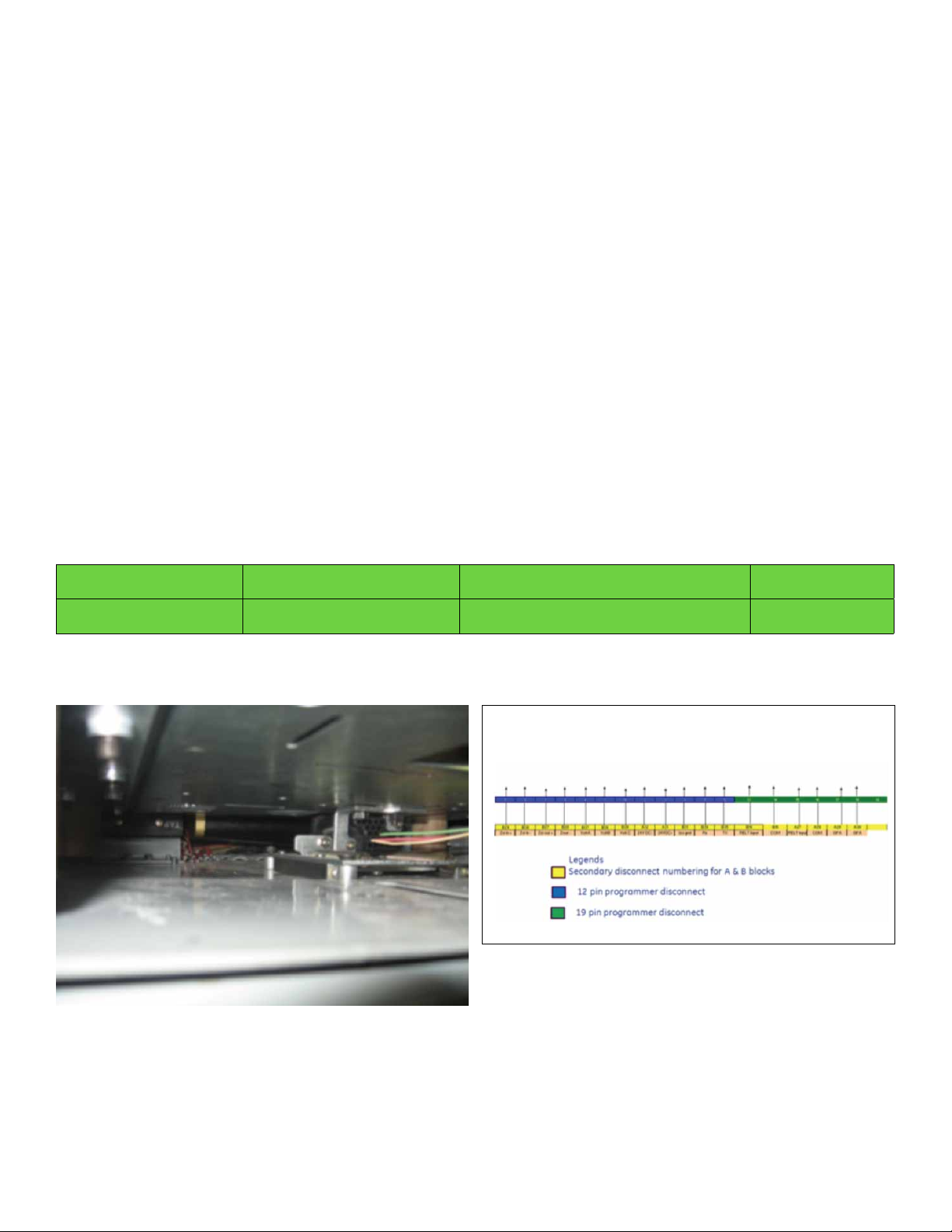
AKD-6—Programmer Secondary Disconnect (Breaker Side)
Programmer disconnect assemblies come pre-installed and wired from the factory and do not require any installation in the field. The photo in Figure 3 shows the 19-pin programmer-disconnect on the AKR30/50, bottom side of the
breaker—already installed. Figure 4 displays the wiring diagram for the programmer-disconnect (12-pin and 19-pin
are combined in one diagram, although the AKD-6 does not use the 12-pin). Figure 5 features an exploded view of
the 19-pin programmer disconnect. An installed view of the 19-pin programmer disconnect appears in Figure 6. For
the compartment side, the 19-pin is ordered separately and comes in a box.
Immediately below, are the part numbers for the 19-pin programmer disconnect assemblies, both breaker side and
compoartment side.
BREAKER SIDE
COMPARTMENT SIDE
Figure 3. 19-Pin Programmer Disconnect
on the AKR30/50 Breaker
P/N 10107108G1
P/N 10106652G1
19-PIN PROGRAMMER DISC ASSY AKD6
19-PIN PROGRAMMER DISC ASSY AKD6
Figure 4. Wiring for Programmer Disconnect
(12 and 19 Pin)
Wiring for programmer 12pin/19pin
DEH-41532 02/12
Programmer Disconnect — Accessory Manual for Retrofil CB
4
Page 6

Figure 5. 19-Pin Programmer Disconnect for
the AKD-6 AKR30H\50H Retrofill, Exploded View
Figure 6. 19-Pin Programmer Disconnect AKD-6
AKR30H\50H Retrofill, Installed
AKD-6—Programmer Secondary Disconnect (Compartment Side)
• Turn off all power to switchgear. Tagout
and lockout main source, up-stream or
main breaker.
• Failure to comply with these instructions
will result in death or serious injury from
severe burns caused by arc flashing that
has exceedingly high temperatures.
• Always wear personal protection equipment
according to OSHA standards and appropriate
to the severity of potential burns.
• Ensure only qualified personnel install, operate, service, and maintain all electrical equipment.
• Installing the programmer disconnect should not be carried out when the compartment is live.
• The compartment should be de-energized before the installing the programmer disconnect assembly.
1. Check the movement of programmer disconnect on slides for biasing.
2. Complete the wiring harness from the programmer disconnect to source wiring.
NOTE: 12-pin programmer disconnect configuration is not provided with the AKD6 version of Retrofils of EntelliGuard ACB.
Programmer Disconnect — Accessory Manual for Retrofil CB
5
DEH-41532 02/12
Page 7

Figure 7 shows the exploded view of the 19-pin programmer disconnect for the AKD-6.
Figure 7. AKD-6—19-Pin Programmer-Disconnect
Assembly, Compartment Side
To install the programmer disconnect in the AKD-6 switchgear, do the following:
1. Turn off power to the switchgear, if not done already.
2. Have these tools ready for doing the task—hand-drill, cleaning solution, antirust, and wrench for metric
M6 bolt/nut.
Clean the base of the compartment of any dirt or foreign particles, if not done already (Figure 8).
Figure 8. Prepare AKD-6—Compartment
DEH-41532 02/12
Programmer Disconnect — Accessory Manual for Retrofil CB
6
Page 8

3. Slide the inner frame assembly to its maximum inserted condition.
4. Note that his position corresponds to the frame position when the breaker would be all the way in and
fully connected.
5. Use the slot, inner semicircle as a datum reference and mark the mounting-hole locations using the template
shown in Figure 9. Dimensions shown are in inches.
6. Drill ¼-inch diameter holes at 4 locations as marked.
Figure 9. AKD-6—Slide the Inner Frame (Dimensioning)
7.
Place the programmer disconnect assembly on the mounting holes and secure it to the base of the programmer
using hardware (Bolt—M6 X 35, Nut—M6 (metric)) provided along with the programmer disconnect assembly kit
(Figure 10).
8. Check the movement of programmer disconnect on slides for biasing.
9. Tighten the hardware hand-tight (Figure 11).
10. From the disconnect plug, route the wire to suitable incoming cables from the compartment.
Programmer Disconnect — Accessory Manual for Retrofil CB
7
DEH-41532 02/12
Page 9

Figure 10. AKD-6—Holes Drilled for Mounting
Programmer Disconnect
Figure 11. AKD-6—Programmer Disconnect Assembly
Secured in Place
AKD-8—Programmer Secondary Disconnect
• Turn off all power to switchgear. Tagout
and lockout main source, up-stream or
main breaker.
• Failure to comply with these instructions
will result in death or serious injury from
severe burns caused by arc flashing that
has exceedingly high temperatures.
• Always wear personal protection equipment
according to OSHA standards and appropriate
to the severity of potential burns.
• Ensure only qualified personnel install, operate, service, and maintain all electrical equipment.
CAUTION:
WIRING
• Before installing the breaker, the programmer disconnect must be wired to the EntelliGuard Breaker.
• Wires with wire markers are provided on the retrofill. Make sure that the switchgear wiring connection
points match up with the original wiring of the cubicle. This ensures that all wiring connections are
properly made.
• Wrong connections will cause the breaker to malfunction.
DEH-41532 02/12
Programmer Disconnect — Accessory Manual for Retrofil CB
8
Page 10

Description
The programmer disconnect consists of two assemblies, one mounted on the breaker side and the second mounted
on the cabinet. The breaker side assembly consists of the mounting bracket, plug assembly. The compartment side
assembly consists of the plug assembly mounted on spring loaded assembly that receives the breaker side plug.
Tools required: Spanner, Flat Head Screw driver, Wire stripper, Wire Cutter, Star type screw driver
Steps to assemble programmer disconnect assembly are as follows:
Identify Existing Programmer Disconnect (Compartment)
The existing programmer disconnect plugs used in AKD8 generation of the AKR breakers are provided on the right
side in case of AKR30/30H/50/50H/30L and on the left side for AKR30S retrofits.
Programmer disconnects are provided with legacy AKR breakers in AKD8 LVS. The breakers were equipped with the
following pin configurations depending on the application
• 9-pin configuration
• 12-pin configuration
• 24-pin configuration
Identify Programmer Disconnect Type to be Installed (with Kit)
The programmer disconnect assembly to be assembled depends on the type of breaker the retrofil is replacing.
These are as follows:
• AKR30/30H/50/50H/30L: In these switchgear, mount the programmer disconnect on the left side wall of the retrofil.
• AKR30S: In these switchgear, mount the programmer disconnect on the right side wall of the retrofil.
Programmer disconnect assemblies are available in two configurations for the Retrofill EntelliGuard ACB:
12-pin configuration: If the legacy LVS has a 12-pin programmer disconnect in use, it can be used with the Retrofill
EntelliGuard ACB. In this case, only the breaker side programmer disconnect assembly needs to be installed.
Programmer disconnects are itemized below.
19-pin configuration: If the legacy LVS doesn’t have a 12-pin programmer disconnect configuration, and the
customer chooses to install a programmer disconnect, then the 19-pin programmer disconnect assembly needs
to be installed in the compartment and the breaker.
Remove Existing Programmer Disconnect (Compartment)
The programmer disconnect assembly must be removed under these conditions:
• 9-pin programmer disconnect assembly is installed in cabinet.
• 24-pin programmer disconnect assembly is installed in cabinet.
• Customer chooses to replace a 12-pin configuration with a 19-pin configuration.
1. Before uninstalling the existing programmer disconnect assembly, make sure that the wiring details are checked
against the wiring numbers. Any changes or deviations need to be noted for use during installation of the new
programmer disconnect.
2. Check that the compartment is de-energized and is safe to work on and the existing breake, if present within the
cabinet, has been removed.
3. Disconnect the wires that connect the terminal block to the compartment programmer disconnect assembly.
Programmer Disconnect — Accessory Manual for Retrofil CB
9
DEH-41532 02/12
Page 11

4. If the customer has chosen to install a 19-pin programmer disconnect assembly in place of a 12-pin programmer
disconnect assembly, the terminal block mounted on the compartment needs to be removed as well. This can be
done by unfastening the two screws that secure the terminal block to the side wall of the compartment.
5. Unfasten the 4 bolts (Figure 12) that hold the programmer disconnect assembly on the wall of the compartment
to remove the compartment side programmer disconnect assembly.
Figure 12. Fasteneres (Bolts) to be Loosened for Remove Programmer Disconnect
Install 19-Pin Programmer Disconnect (Compartment and Breaker)
1. Unpack the 19-pin programmer disconnect assembly from the box. Each box of programmer disconnect assembly
has a 20-pin terminal block supplied.
2. Check that the programmer disconnect plug assembly is not damaged and the wiring is intact.
3. Check that the programmer disconnect block is moving freely within the assembly and retracts to its original
position by spring loading when it is slid back to its fully activated state.
4. Check for electrical continuity between the contact pins on one and and the wire termination on the other.
Blocks containing faulty pins should not be used for installation.
5. Install the new terminal block on the side wall of the the compartment and land the incoming wires from the
compartment to the terminal block. Any additional wires from the compartment side, required for the 19 pin
programmer, need to be landed on the terminal block and checked for electrical continuity.
6. Mount the programmer disconnect assembly on the side wall of the compartment where the original programmer
disconnect assembly was mounted.
7. Land the wires from the programmer disconnect to the terminal block mounted earlier.
8. Check for continuity between the terminal block contact points to the corresponding pins on the programmer
disconnect. This should match against the wiring scheme planned for the new 19-pin programmer disconnect
assembly on the compartment.
DEH-41532 02/12
Programmer Disconnect — Accessory Manual for Retrofil CB
10
Page 12
Wiring and Task Completed
1. The breaker side programmer disconnect assemblies comes pre-installed and wired from the factory. Hence no
action is needed on the breaker.
2. Verify that the compartment side programmer disconnect assembly wiring scheme matches that of the breaker
side wiring scheme.
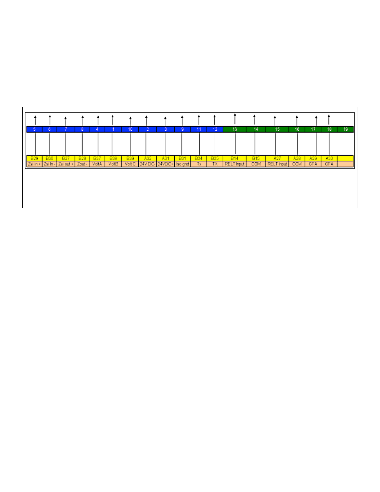
3. A typical wiring diagram used for the programmer disconnect on the breaker side is shown in Figure 13.
Figure 13. Typical Programmer disconnect Wiring Scheme for Retrofill EntelliGuard ACB in AKD8 LVS
• Top row: Terminal numbering on programmer disconnect
• Bottom row: Terminal number for A & B Secondary disconnects of EntelliGuard breaker
• Arrows point to the terminal blocks.
Programmer Disconnect — Accessory Manual for Retrofil CB
11
DEH-41532 02/12
Page 13

Wiring Diagram for the AK/AKR Retrofill
DEH-41532 02/12
Programmer Disconnect — Accessory Manual for Retrofil CB
12
Page 14

Notes
Programmer Disconnect — Accessory Manual for Retrofil CB
13
DEH-41532 02/12
Page 15

GE Energy
41 Woodford Avenue
Plainville, CT 06062
www.geindustrial.com
© 2012 GE Company
imagination at work
DEH-41532 02/12
 Loading...