

Page 1
gg
GEH-6468A Instructions
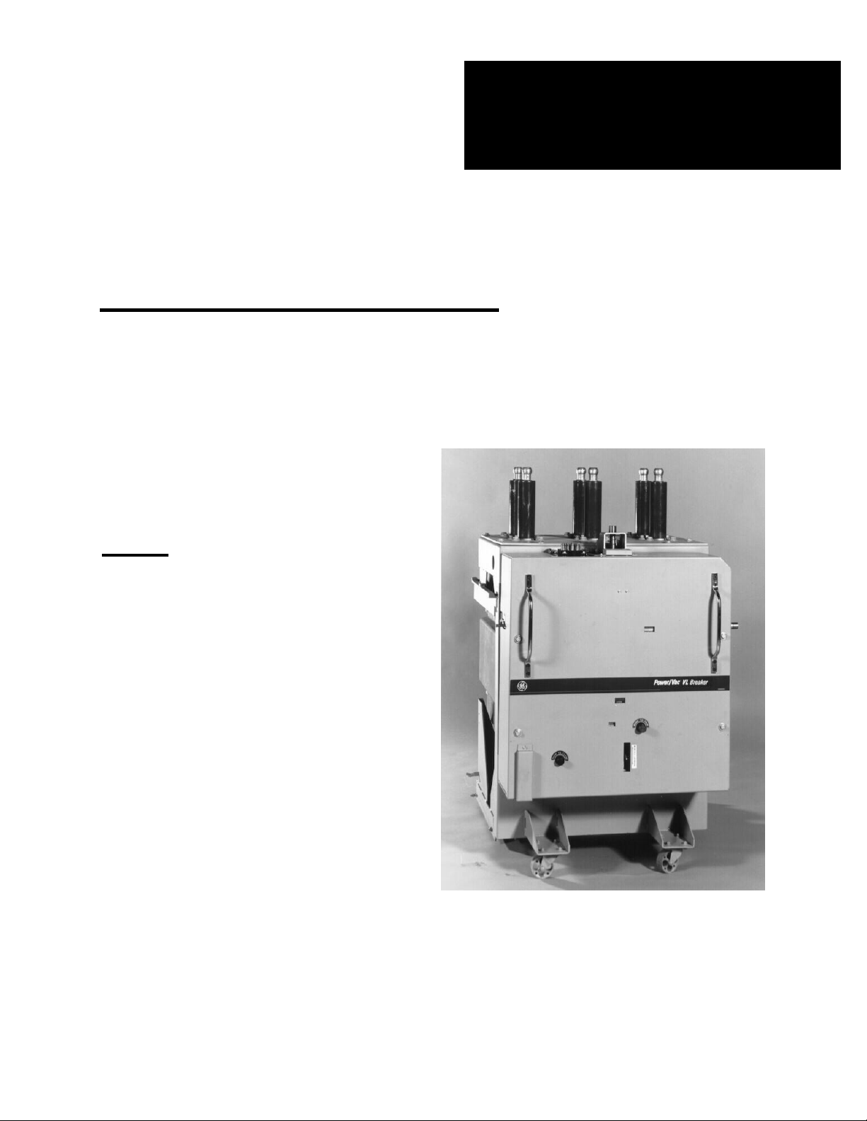
GE PowerVac® VL
Vacuum Circuit Breaker
TYPE
PV-VL 13.8-500-0 and -1
PV-VL 13.8-750-0 and -1
PV-VL 13.8-1000-0 and -1
With ML-18VL Mechanism
Page 2

Page 2 GEH 6468A - Power/Vac VL Breaker
Page 3

CONTENTS
1. INTRODUCTION 5
1.1 SAFETY 5 11.4 CLOSE COIL PLUNGER GAP 31
2. DESCRIPTION 5
3. RECEIVING, HANDLING AND STORAGE 6 12. ELECTRICAL CHECKS 31
3.1 RECEIVING 6 12.1 ELECTRICAL OPERATION 31
3.2 HANDLING 6 12.2 HIGH-POTENTIAL TEST 31
3.3 STORAGE 6 12.2.1 PRIMARY CIRCUIT 31
3.4 PACKING LIST 6 12.2.2 SECONDARY CIRCUIT 32
4. INITIAL INSTALLATION PROCEDURES 7
4.1 DOOR WIRING INTERFERENCE 7 12.5 INSULATION TESTS 33
4.2 POSITIVE INTERLOCK
TEST PROCEDURES 7
4.3 BY-PASS KIT INSTALLATION 7
4.4 CHECKING FOR PROPER INTER LOCK AND TRIP FREE FUNCTIONS 14.1 GENERAL 33
BEFORE LOWERING THE BREAKER 14.2 SERVICE CONDITIONS 34
FROM THE ELEVATED POSITION 8 14.3 FAULT INTERRUPTION 34
5. ADJUSTMENTS TO BREAKERS /
SWITCHGEAR INTERFACES 8
5.1 STATIONARY AUXILIARY SWITCH 8 14.7 PRIMARY INSULATION PARTS 35
5.2 PRIMARY CONTACT PENETRATION 9 14.8 LUBRICATION 35
5.3 POSITIVE INTERLOCK 9 14.9 RECOMMENDED MAINTENANCE 35
5.4 SECONDARY COUPLER 10
5.5 SPRING DISCHARGE CAM 10
5.6 STOPS 10
5.7 GROUND 10
5.8 POSITION SWITCH 10
6. TYPICAL WIRING DIAGRAMS 11
7. FEATURES 27
7.1 SAFETY PRECAUTIONS 27 17.4 MECHANISM 37
7.2 INTERLOCKS 27 17.5 CONTROL SWITCHES 37
7.2.1 RATING INTERFERENCE PLATE 27 17.6 TRIP COIL REPLACEMENT 37
7.2.2 POSITIVE INTERLOCK SYSTEM 27 17.7 CLOSING COIL REPLACEMENT 37
7.2.3 SPRING DISCHARGE SYSTEM 27 17.8 AUXILIARY SWITCH
8. OPERATION 28
8.1 CLOSE SPRING CHARGING 28
8.2 CLOSING OPERATION 29
8.3 OPENING OPERATION 29 18.1 ORDERING INSTRUCTIONS 38
8.4 TRIP-FREE OPERATION 29
9. CONTROL CIRCUIT 29
10. MECHANICAL CHECK AND
SLOW CLOSE 29
10.1 VISUAL INSPECTION 29 19.5 CLOSE COIL PLUNGER 39
10.2 CLOSING SPRING CHARGING 29 19.6 CLOSE SPRING INTERLOCK 39
10.3 CLOSING SPRING GAG 30 19.7 POSITIVE INTERLOCK 39
10.4 SLOW CLOSING 30
10.5 GAG TOOL REMOVAL 30
11.3 CONTACT GAP 30
11.5 TRIP COIL PLUNGER GAP 31
11.6 CONTROL SWITCH ADJUSTMENT 31
12.3 PRIMARY CIRCUIT RESISTANCE 32
12.4 VACUUM INTEGRITY TEST 32
13. CHECKING AND INSTALLATION 33
14. MAINTENANCE 33
14.4 CONTACT EROSION 34
14.5 TRANSFER FINGER WEAR 35
14.6 MECHANISM 35
15. TIMING 36
16. OPENING AND CLOSING SPEED 36
17. REPAIR AND REPLACEMENT 36
17.1 GENERAL 36
17.2 REPLACING INTERRUPTERS 36
17.3 PRIMARY DISCONNECTS 37
37
REPLACEMENT
17.9 MOTOR REPLACEMENT 38
17.10 “Y” RELAY REPLACEMENT 38
18. RENEWAL PARTS 38
19. MECHANICAL ADJUSTMENTS 38
19.1 GENERAL 38
19.2 WIPE ADJUSTMENT 38
19.3 CONTACT GAP ADJUSTMENT 39
19.4 TRIP COIL PLUNGER 39
11. DIMENSIONAL CHECKS 30
11.1 PRIMARY CONTACT EROSION 30
11.2 SPRING WIPE 30 STATIONARY CUBICLE INFORMATION 62
LIST OF ILLUSTRATIONS 4
INDEX
70
GEH 6468A - Power/Vac VL Breaker Page 3
Page 4

LIST OF ILLUSTRATIONS
FIGURE PAGE
1 INTERIOR VIEW OF STATIONARY CUBICLE 12
2 INTERLOCK MODIFICATION 13
3 MOTOR OPERATOR SWITCH ACTUATOR 14
4 ELEVATING MOTOR TROUBLESHOOTING 15
5 SCHEMATIC DIAGRAM - VERTICAL LIFT DRIVE MECHANISM 16
6 STATIONARY STRUCTURE WIRING 17
7 BY-PASS KIT INSTALLATION 18
8 BREAKER WIRE DIAGRAM (typical) OLD MS MECHANISM 19
9 BREAKER WIRE DIAGRAM (typical) OLD ML MECHANISM 20
10 ADJUSTMENT OF PLUNGER INTERLOCK 21
11 PRIMARY CONTACT PENETRATION 22
12 POSITIVE INTERLOCK ROLLER 23
13 POSITIVE INTERLOCK 1000 MVA UNITS 24
14 POSITIVE INTERLOCK M-26 UNITS 25
15 POSITIVE INTERLOCK M-36 UNITS 26
16 FRONT VIEW WITH FRONT COVER 44
17 FRONT VIEW WITHOUT COVER 45
18 MANUAL CHARGING HANDLE 46
19 CLOSING SPRING GAG ACCESS 47
20 TOGGLE LINKAGE POSITIONS 48-50
21 CONTACT EROSION INDICATOR 51
22 OPERATING ROD ASSEMBLY 52
23 ML-18VL MECHANISM 53-54
24 TRIP COIL LINKAGE 55
25 CLOSE COIL AND LINKAGE 56
26 FRONT VIEW OF ML-18VL MECHANISM 57
27 CONTACT GAP 58
27a CONTACT GAP ADJUSTMENT 59
28 FLEX CABLE CONNECTION 60
29 SAMPLE OPERATING SPEED GRAPHS 61
30 CLOSE COIL PLUNGER GAP 62
31 CONTROL SWITCHES 63
32 TRIP COIL PLUNGER GAP 64
33 SPRING WIPE 64
INDEX 70
TROUBLE REPORTING FORM 68-69
TABLE OF MEASUREMENTS AND ADJUSTMENTS 40
ADDENDUM TO GEH-1802 (CUBICLE) 62
Page 4 GEH 6468A - Power/Vac VL Breaker
Page 5

These instructions do not purport to cover all details or variations in equipment nor to provide for every
possible contingency to be met in connection with installation, operation or maintenance. Should further
information be desired or should particular problems arise which are not covered sufficiently for the
purchaser's purposes, the matter should be referred to the Seller.
To the extent required, the products described herein meet applicable ANSI, IEEE and NEMA standards, but no
such assurance is given with respect to local codes and ordinances because they vary greatly.
POWER/VAC® VL
VACUUM CIRCUIT BREAKER
WITH ML-18VL MECHANISM
1. INTRODUCTION
1.1. SAFETY
IT IS IMPERATIVE THAT ALL PERSONNEL
ASSOCIATED WITH THIS EQUIPMENT READ
AND COMPLETELY UNDERSTAND THE
WARNINGS LOCATED THROUGHOUT THIS
INSTRUCTION BOOK. FAILURE TO DO SO
CAN RESULT IN DAMAGE TO PROPERTY,
PERSONAL INJURY OR DEATH.
Each user must maintain a safety program for the
protection of personnel, as well as other equipment,
from the potential hazards associated with
electrical equipment.
The following requirements are intended to
augment the user’s safety program but NOT
supplant the user’s responsibility for devising a
complete safety program. The following basic
industry practiced safety requirements are
applicable to all major electrical equipment such as
switchgear or switchboards. GE neither condones
nor assumes any responsibility for practices which
deviate from the following:
1. ALL CONDUCTORS MUST BE ASSUMED TO
BE ENERGIZED UNLESS THEIR POTENTIAL
HAS BEEN MEASURED AS GROUND AND
ADEQUATE CAPACITY GROUNDING ASSEMBLIES HAVE BEEN APPLIED TO PREVENT ENERGIZING. Many accidents have
been caused by unplanned energization from
non-recognized back feeds, equipment
malfunc-tions, and from a wide variety of
sources.
3. Although interlocks to reduce sone of the risks
are provided, the individual’s actions while
performing service of maintenance are
essential to prevent accidents. Each person’s
know-ledge; mental awareness; and planned
and executed actions often determine if an
accident will occur. The most important
method of avoiding accidents is for all
associated personnel to carefully apply a
thorough understanding of the specific
equipment from the viewpoints of its purpose,
its construction, its operation and the situations
which could be hazardous.
All personnel associated with installation, operation
and maintenance al electrical equipment, such as
power circuit breakers and other power handling
equipment, must be thoroughly instructed, with
periodic retraining, regarding equipment in general
as well as the particular model of equipment which
they are working.
Instruction books, actual devices and appropriate
safety and maintenance practices such as OSHA
publications, National Electric Safety Code (ANSI)
C2), National Electric Code, and National Fire
Protection Association (NFPA) 70B Electrical
Equipment Maintenance must be closely studied
and followed. During actual work, supervision
should audit practices to assure conformance.
It is strongly recommended that all equipment be
completely de-energized, verified to be “dead”,
then grounded with adequate capacity grounding
assemblies prior to any maintenance.
2. It is strongly recommended that all equipment
be completely de-energized, verified to be
“dead”, then grounded with adequate capacity
grounding assemblies prior to any
maintenance. The rounding cable assemblies
must be able to withstand energizing fault
levels so that protective equipment may clear
the circuit safety. Additional discussion on this
concept is covered in Chapter 20 of ANSI/
2. DESCRIPTION
The PowerVac® VL vacuum circuit breaker is a
vertical lift, removable and interchangeable interrupting element, for use in metal-clad switchgear to
provide protection and control of electrical
apparatus and power systems. The PowerVac® VL
Type PV-VL circuit breaker with ML-18VL mechan-
NFPA 70B, Electrical Equipment Maintenance.
GEH 6468A - Power/Vac VL Breaker Page 5
Page 6

ism is available in continuous current ratings of
1200, 2000 and 3000 amperes in accordance with
industry standards. In addition, extended ratings of
3500, (not part of the original Magnablast offering)
and 4000 amperes is available as well as a 5000
ampere fan cooled option. Refer to the breaker
nameplate for complete rating information of any
particular breaker. The nameplate also describes
the control power requirements for that breaker.
The application of a breaker must be such that its
voltage, current and interrupting ratings are never
exceeded. Since this book is written to include all
ratings of the breaker, as well as several design
variations, the instructions will be of a general
character and all illustrations will be typical unless
otherwise specified.
3. RECEIVING, HANDLING AND STORAGE
3.1. RECEIVING
Breakers should be carefully protected against condensation, preferably by storing in a warm, dry
room of moderate temperature such as 40 to 100°
F. High humidity may have an adverse effect on
the insulating parts and should be avoided.
Circuit breakers for outdoor metal-clad switchgear
should be stored in the equipment only when power
is available and the heaters are in operation to
prevent condensation.
Rollers, latches, etc. of the operating mechanism
should be coated with GE part No. 0282A2048P009
(Mobil 28 red) grease to prevent rusting.
If the breaker is stored for any length of time, it
should be inspected periodically to see that
corrosion has not started. Should the breaker be
stored under unfavorable atmospheric conditions, it
should be serviced before being placed on line.
Each breaker is carefully inspected before
shipment. Immediately upon receipt of the circuit
breaker, an examination should be made for any
damage sustained in transit. If injury or rough
handling is evident, a claim should be filed
immediately with the transportation company, and
the nearest GE Sales Office should be notified.
3.2. HANDLING
It is expected that care will be exercised during the
unpacking and installation of breakers so that no
damage will occur from careless or rough handling,
or from exposure to moisture or dirt. Loose parts
associated with the breaker are sometimes
included in the same crate. Check all parts against
the packing list to be sure that no parts have been
overlooked.
3.3. STORAGE
It is recommended that the breaker be put into
service immediately in its permanent location. If
this is not possible, the following precautions must
be taken to assure the proper storage of the
breaker.
The breaker should be stored in a clean location,
free from corrosive gases or fumes. Particular care
should be taken to protect the equipment from
mois- ture and cement dust, as this combination
has a very corrosive effect on many parts.
3.4 PACKING LIST
With your breaker, you should have received:
1. Manual charging handle. (Part No.
0282A7227P001)
2. Gag tool. (Part No. 0209B8043G003)
3. Breaker Instruction Book - Contact your GE
office for additional copies or verification of
present revision.
4. (1) piece of edge protector (See section 4.1)
5. (12) wire ties. (See section 4.1)
6. Lower blocking plate and screws for lower
notch in positive interlock cam plate in existing
breaker cell units. (Kit # 254-089) NOTE: This
assembly eliminates the test provision for
closing the breaker in the cabinet, except in the
“connect” position, as has been recommended
to improve safety of the VL equipment.
7. Existing unit wiring and device WARNING
NOTICE sheet.
8. (1) GE tool parts kit (0282A3060G003) with
each breaker order of single or multiple
breakers.
9. A spring discharge interlock cam - to be
installed if none exists in your switchgear cell.
NOTE: Customer option to implement, if
required.
10. GE grease Part No. 0282A2048P009.
Contact your local GE office if you have not
received the above materials.
Page 6 GEH 6468A - Power/Vac VL Breaker
Page 7

4. INITIAL INSTALLATION PROCEDURES
Although GE has made every effort to assure
interchangability and satisfactory interface with
existing equipment, older equipment and field
modifications made over the years, may require
additional procedures before the new vacuum
breaker can be installed in the cubicle.
4.1 DOOR WIRING INTERFERENCE
In some of the older GE Metal-Clad switchgear
units, the wiring from the door to the stationary
structure was run through a perforated steel wire
assembly grill. (Figure 1.)
As the new replacement breaker is elevated, the
front cover MAY interfere with the subject wiring
grill, approximately 4” to 6” before the final
connected position.
The front cover shield on the replacement breaker
is wider than all previous AM breaker units. Due to
the large forces required to operate the existing
stationary auxiliary switches, the operating
mechanism cannot be decreased in width.
If this condition exists, use the modification kit
shipped with the breaker and make the following
modifications to the switchgear cubicle.
The lower “Vee” notch in the positive interlock cam
plate allows closing and opening the breaker
electrically.
FOR IMPROVED SAFETY, IT IS
RECOMMENDED THAT THE ABILITY TO
FUNCTIONALLY OPER-ATE THE BREAKER IN
THE “TEST” POSITION BE ELIMINATED AND
THAT BREAKER FUNC-TIONAL TESTING BE
PERFORMED WITH THE BREAKER
COMPLETELY REMOVED FROM THE CUBICLE.
4.3 BY-PASS KIT INSTALLATION
(See Figures 2 & 7).
The ability to electrically close and open the
breaker in the “Test Position” is eliminated by
covering the lower Vee notch in the positive
interlock cam plate. Materials for accomplishing
this modification are provided in Kit #254-089
furnished with the new vacuum breaker. This bypass kit should be in-stalled on GE breaker cubicles
that have a lower interlock roller Vee notch on the
positive interlock cam plate. Some GE breaker
cubicles do not have this lower Vee notch on the
interlock cam plate. In that case, the by-pass kit is
not required. If addi-tional by-pass kits are required
for the remainder of the switchgear line-up, order
Kit #254-089.
1. Cut out the bottom section of the grill as shown
in figure 1 on page 12.
2. Cover the sharp edges with the edge protector
furnished with the breaker accessories.
3. Fold any wire back and re-tie with the furnished
wire ties.
4. Elevate the replacement breaker in accordance
with the instructions.
4.2 POSITIVE INTERLOCK TEST
PROCEDURES
The positive interlock system functions to prevent
closing the breaker contacts when the breaker is
being raised or lowered and prevents raising or
lowering the breaker when the breaker contacts are
closed. In most AM breaker Metal-Clad Switchgear
units, there is a breaker “Test Position” which
allows you to functionally test the breaker without
connecting to the bus. This position is usually about
5” out from the breaker being fully inserted into the
cubicle. When in the “test position”, a secondary
coupler cable must be used to connect the
secondary control circuits since the breaker is
fully lowered position.
WARNING: FAILURE TO FOLLOW THE
INSTRUCTIONS BELOW COULD CAUSE
A CLOSED BREAKER TO BE RAISED
TOWARDS THE CONNECTED POSITION,
CAUSING INJURY OR DEATH TO THE
OPERATOR AND EXTENSIVE EQUIPMENT
DAMAGE.
To make the modification proceed as follows:
1. Remove the existing clutch switch cover plate
and discard (save the mounting hardware).
2. Measure and record the distance from the
bottom of the cam plate to the bottom of the switch
operator bracket. See Figure 2.
3. Remove the existing switch operator bracket.
4. Install the new switch operator bracket supplied
with the kit, using the two existing ¼ - 20 screws.
Adjust the bracket in the exact same location as the
removed bracket, in relation to the motor activation
switch lever. Make sure that the lower notch in the
positive interlock cam plate is covered and that the
edge is even with the front edge of the positive
interlock cam plate. (Figures 2 and 7.)
GEH 6468A - Power/Vac VL Breaker Page 7
Page 8

5. Drill two #22 (.157) diameter holes in the
positive interlock cam plate from locations in new
bracket supplied with kit. See Figure 2.
6. Install two #10-24 thread cutting screws
(supplied with kit).
must remain locked and not allow the motor handle
to be moved far enough to engage the clutch and
close the clutch switch contacts that energize
the motor circuit. There should be 1/16” clearance
between the clutch and motor coupler, when the
motor handle is pulled forward. See Figure 7(A).
7. Install the new clutch switch cover plate
supplied with the kit using the existing hardware.
8. All breaker cubicles that undergo this modification to the positive interlock cam plate must be
checked according to the dimensions given in
Figure 7.
a. The 10-7/8” +1/16” -0” dimension from the
breaker to the front edge of the positive interlock
cam plate must be verified and maintained prior to
inserting a replacement PVVL vacuum breaker into
the cubicle. See Figure 7(C).
b. The 1/16” clearance between the stationary
flag, just behind the upper “Vee” notch and the
interlock roller must be maintained or reset if
required. The breaker should be in the fully raised
position. See Figure 7(A).
4.4 CHECKING FOR PROPER INTERLOCK
AND
TRIP FREE FUNCTIONS BEFORE LOWER ING THE BREAKER FROM THE ELEVATED
POSITION.
When the breaker is in the fully elevated and
connected position, releasing the motor operating
handle will return the positive interlock roller into
the upper notch in the interlock cam plate, closing
the interlock switches and energizing the circuit
that will charge the springs. The breaker may now
be closed.
In order to lower the breaker from the connected
position, the breaker must be open. If the breaker
is not open, the operator can not, and should not
be able to engage the clutch or activate the motor
circuit. The positive interlock roller will remain
locked and will not allow the interlock cam plate to
move vertically far enough to activate the
elevating motor.
To test the function of the positive interlock system
and trip free function, the following checks should
be made:
1. With the breaker closed and in the elevated
position, the positive interlock roller on the breaker
2. Disconnect the elevating motor plug from its
socket.
3. Trip the breaker to the open position.
4. Using the manual charging handle, charge the
closing springs in the breaker until the semaphore
shows “charged”.
5. Pull back the elevating handle on the motor so
that the interlock roller is at the dimension shown in
Figure 7. (11/16” +0 -1/16) Hold it in this position
while pressing the manual close push button on the
breaker. The main power springs must discharge
and the breaker must remain open, as indicated by
the semaphores on the front of the breaker. This
indicates that the breaker contacts will not close
during raising or lowering the breaker.
5. ADJUSTMENTS TO BREAKER/SWITCH GEAR INTERFACES.
The interfacing parts on all ratings of type AM
breakers and switchgear are functionally the same.
5.1 STATIONARY AUXILIARY SWITCH (MOC)
The Stationary Auxiliary Switch is an optional
switch mounted in the switchgear cubicle. When
the breaker has been elevated to the fully
connected position, the switach will be actuated
whenever the breaker is closed. The switch is
actuated by the plunger interlock (plunger)
mounted on the top of the breaker mechanism.
The switch has a number of “a” contacts (closed
when the breaker is closed and open when the
breaker is open) and “b” contacts (open when the
breaker is closed and closed when the breaker is
open). The following paragraph defines the
essential dimensions relating to the interfacing
elements of the breaker and switchgear, to assure
reliable performance.
The following elements are important factors which
commonly affect the operation of the stationary
auxiliary switch.
1. Plunger travel on the breaker.
Page 8 GEH 6468A - Power/Vac VL Breaker
Page 9

2. The gap between the top of the plunger on the
breaker and the bottom of the rod on the stationary
auxiliary switch mechanism.
3. Variations between breakers in the distance
from the underside of the lift rail and the top of the
plunger.
4. Variations in the rotation requirements to
“make” and “break” the stationary auxiliary switch
contacts.
5. Condition of the plunger interlock components
on the breaker.
6. Elevating mechanism limit switch consistency.
7. Breaker elevating mechanism positive stops.
8. Seismic events.
Some of these elements also affect the other
important interfaces required for reliable operation
of the equipment, such as:
1. Primary disconnect penetration.
2. Secondary coupler penetration.
3. The positive interlock mechanism.
A major goal in the design of switchgear has
always been the interchangeabililty of breakers.
GE Switchgear has been very successful in
achieving that goal for many years. Analysis of
instruction book adjustments, shop tolerances, and
service advice letters issued in recent years,
however, has demonstrated that tolerances in
switchgear equipment installed and presently
operating can result in situations where it is
impossible to meet all adjustments or that an
adjustment is brought into specification and it
causes a problem with another interface.
With specific reference to the plunger / stationary
auxiliary switch interface, the following instructions
and recommendations supersede all previous
Service Advice Letters and instructions. Refer to
Figure 1 for details.
Nominal breaker plunger travel is 1-1/8”. Nominal
auxiliary switch rod travel is 1-1/16”. It is
imperative that a gap is present between the top of
the plunger and the bottom of the rod, when the
breaker is in the fully connected position and the
breaker is open.
To assure the most reliable switch operation, it is
recommended that the plunger travel be measured
for each breaker and recorded in maintenance
records. It is further recommended that the
auxiliary switch mechanism be adjusted, if
necessary, to result in a gap that is in accordance
with the table given in Figure 10. It may require the
roll pin which
secures the auxiliary switch mechanism plate to be
removed and a new hole drilled after loosening the
two mounting bolts and moving the entire auxiliary
switch mechanism up or down.
This action may mean future adjusting when and if
different breakers are interchanged. Reliable
switch operation is critical and it may require
limiting your interchangeability of breakers. At a
minimum, the criticality requires adjustment
verification when swapping breakers.
Specifically, paragraph (f) on page 11 of Service
Advice Letter (S.A.L.) #073-323-1, dated 02-01-78
is rescinded and the instruction in GEH-1802X on
gap clearance is rescinded and both are replaced
with the gap dimension (“G”) given in the table of
Figure 10.
The plunger dimensions given in the breaker
instruction books are not rescinded because they
are correct nominal dimensions. It is permissible to
let the breaker adjustment be out of specification, if
it conflicts with the dimensions given in Figure 10.
5.2 PRIMARY CONTACT PENETRATION
The nominal contact penetration is 7/8” as shown
in Figure 11. The tolerance on penetration is plus
5/32”, minus 1/8” on non 1E equipment and plus
1/16”, minus 1/8” on 1E equipment.
Reference Service Advice Letter # 073.323.1,
which addresses methods to check both the
penetration and the contact wipe for 5kV
equipment. The same methods and means of
adjustment also apply to 15kV equipment. GEH1802X and the similar illustrations it contains
showing proper contact wipe patterns should also
be consulted. It is essential to maintain proper
contact penetration while maintaining the
stationary auxiliary switch adjustment given in
Figure 10.
5.3 POSITIVE INTERLOCK
The purpose of the positive interlock it to prevent
moving the breaker to or from the connected
position while the main contacts are closed, and to
prevent closing the contacts unless the breaker is
in the fully connected position. These important
safety features are achieved by means of the
positive interlock roller on the right side of the
breaker and positive interlock cam and stationary
“flag” on the switchgear, as shown in Figure 7.
GEH 6468A - Power/Vac VL Breaker Page 9
Page 10

The following adjustments are made at the factory
and verified for proper operation per Figure 7. The
distance from the top of the stationary flag to the
top of the switchgear guide rails is set. This
maintains the surface upon which the breaker
wheels rest when the breaker is lowered. The
upper elevating motor limit switch is then adjusted
to achieve a roller to flag clearance of 1/16” to 1/8”
as shown in Figure 7. The limit switch de-energizes
the elevating motor circuit and should be activated
when the primary disconnects and secondary
coupler reach their nominal contact penetration
position. If the timing of this sequence is off, the
cubicle must be adjusted back to factory
specifications.
Instructions for positive interlock adjustment are
detailed on Figures 13, (1000 MVA Equipment),
Figure 14, (M-26 Equipment); and Figure 15, (M-36
Equipment). These adjustments are also detailed
in instruction book GEH-1802X.
5.4 SECONDARY COUPLER
The cam has minimal adjustment provision. The
holes may be slightly slotted to adjust the cam
vertically to allow discharge when the breaker
wheels reach 1/8” to ¼” height above the floor.
Refer to GE drawing 0184B7344 for instructions on
installing a spring discharge cam in the switchgear
cubicle.
5.6 STOPS
The stop pins and stop bolts on the elevating
mechanism are emergency mechanical stops
which would come into use only if the upper
elevating motor switch is completely out of
adjustment or has failed. Elevating against these
stops may be quite audible and the operator should
release the clutch handle, de-energizing the
elevating motor circuit or, the elevating motor
circuit protective fuse will open to protect the
motor. The stop bolts should be set to 3/32 to 1/8”
clearance and only set after all other elevating
adjustments are made.
On the top front of the breaker, there is a black
plastic block which holds male secondary coupler
pins. This block should make contact with, and
slightly raise a spring loaded black plastic block
which holds female secondary coupler sockets on
the switchgear. The contact depression should be
1/8”. The stationary block is adjustable in the
vertical direction as described in Service Advice
Letter 073-323-1. It is not always possible to have
the black plastic blocks in contact over their entire
flat surface. Often, the rear of the blocks are
engaged while a gap exists along the front edge.
This is an acceptable condition. The contacting
block surfaces should touch and the female block
edge move upward between 1/32” to 1/8”.
5.5 SPRING DISCHARGE CAM
The purpose of the spring discharge interlock is to
discharge all stored energy in the breaker
mechanism whenever the breaker is withdrawn
from the cubicle. The discharge interlock is located
on the left side of the breaker. The spring
discharge cam mounted in the switchgear should
discharge the breaker closing spring when the
breaker is lowered.
5.7 GROUND
A visual check should be made to observe the
ground connection. The ground shoe on the
moveable breaker is designed to have a nominal
engagement of 1-½” + ¼” vertically with the steel
and copper spring loaded disconnects of the
ground device in the switchgear.
5.8 POSITION SWITCH (TOC)
The position switch is an optional device mounted
in the rear left side of the switchgear cubicle. The
switch contacts operate when the lifting
mechanism is in either the fully raised or fully
lowered position. Switch operation should be
checked with the breaker withdrawn manually and
the equipment de-energized, and again electrically,
with the breaker in the cubicle. Refer to Service
Advise Letter 073-326.1, dated 5-23-78 for a
description of design changes made to improve the
switch operating mechanism in 1978.
6. TYPICAL WIRING DIAGRAMS
Page 10 GEH 6468A - Power/Vac VL Breaker
Page 11

Figures 8 and 9 show typical wiring diagrams for
PowerVac® VL breakers.
Replacement breakers for old units with solenoid
mechanisms (AM breakers with MS type mechanisms) are typically wired per the drawing in
Figure 8.
Replacement breakers for old units with stored
energy mechanisms (AM breakers with ML type
mechanisms). are typically wired per the drawing in
Figure 9.
The wiring on your breakers may be different.
Consult your nameplate for the correct drawing
number and call your local GE office for additional
copies of this drawing are required.
GEH 6468A - Power/Vac VL Breaker Page 11
Page 12
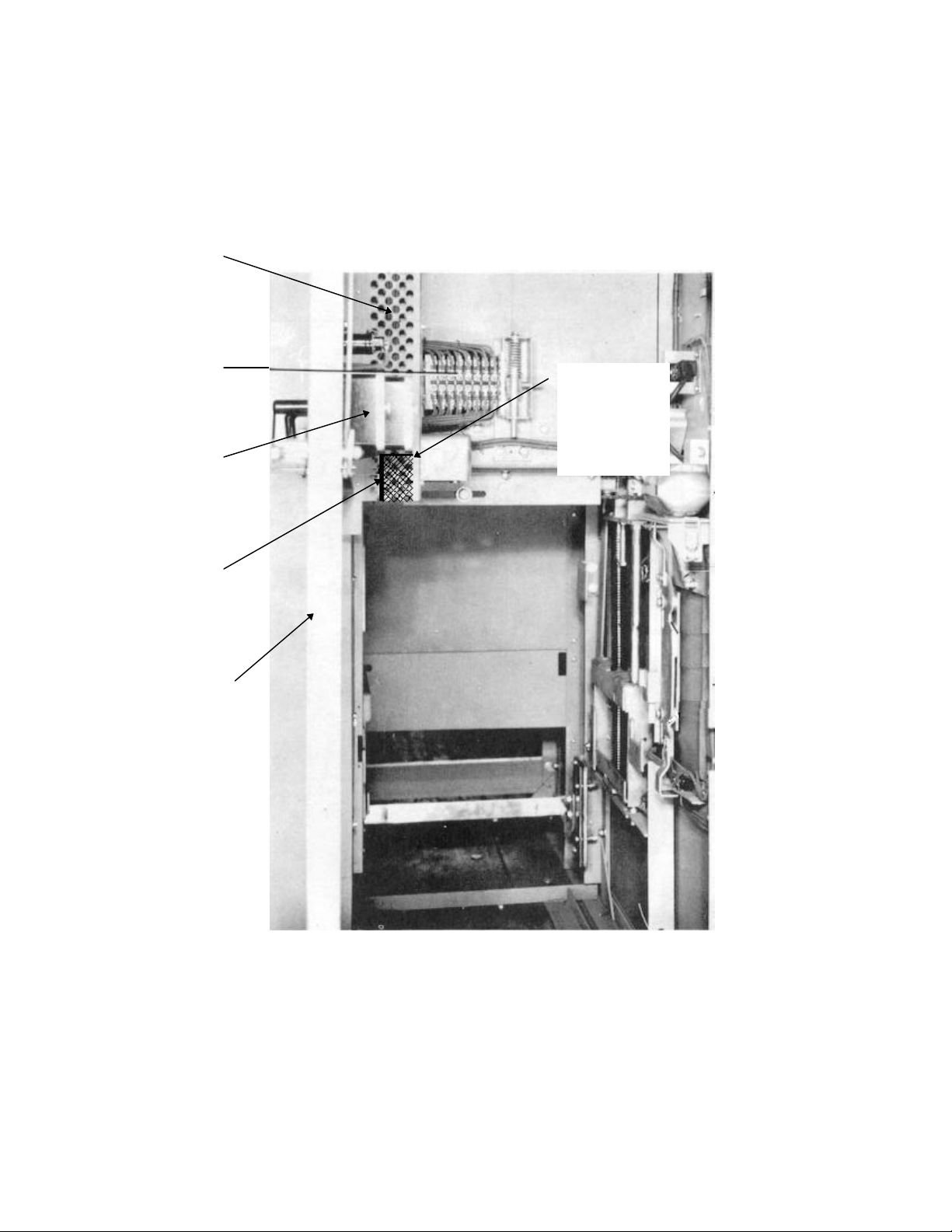
Wire Grill
Stationary
Aux Switch
SB Control
Switch
FIGURE 1
INTERIOR VIEW OF STATIONARY CUBICLE
Grill
Cutout
Edge Protector
Front Door
Page 12 GEH 6468A - Power/Vac VL Breaker
Page 13
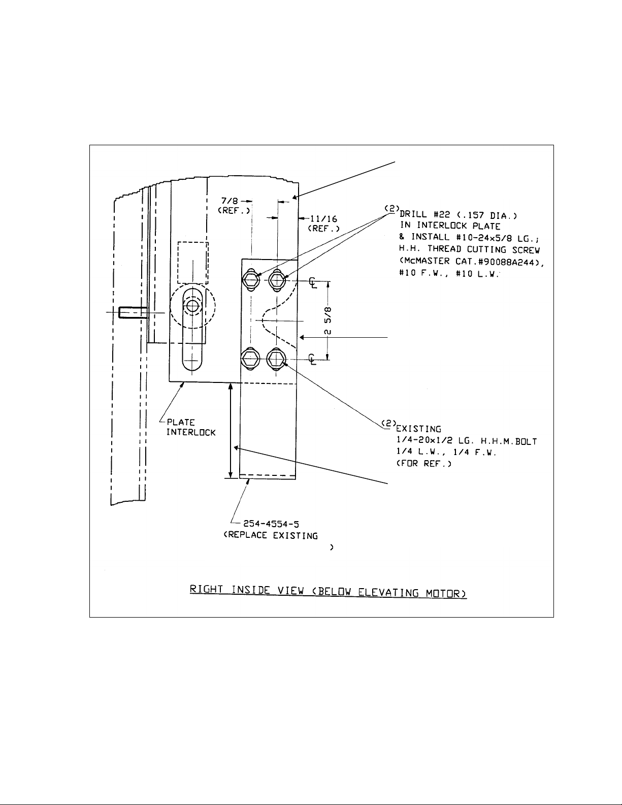
FIGURE 2
INTERLOCK MODIFICATION
New Switch Operator Bracket
(Shown Blocking Lower Notch)
Positive Interlock Cam Plate
Record this dimension before
removing old switch operator
bracket.
New bracket should be adjusted
to this dimension.
SWITCH OPERATOR BRACKET
GEH 6468A - Power/Vac VL Breaker Page 13
Page 14
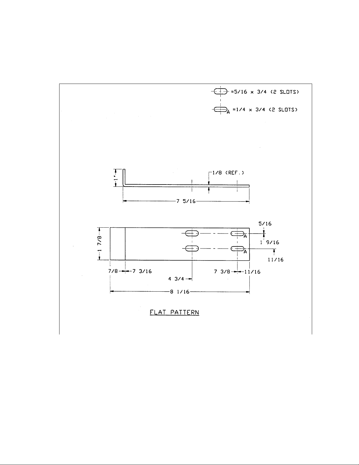
FIGURE 3
MOTOR OPERATOR SWITCH ACTUATOR
Page 14 GEH 6468A - Power/Vac VL Breaker
Page 15

ELEVATING MOTOR TROUBLESHOOTING
TROUBLE SHOOTING
IF ELEVATING MOTOR DOES NOT OPERATE:
1. Check power supply
2. Check fuses UL
FIGURE 4
CORRECTIONS
3. Check and adjust mechanical clutch linkage to clutch switch LC
4. Check LC for proper performance
5. Check motor switch
6. Check motor
7. Adjust upper LE and lower LF limit switches for proper breaker position
8. Check and adjust leaf springs to provide proper tilt to operate limit switches
9. Check plug and receptacle for proper connections
10. Check clutch and mechanism
GEH 6468A - Power/Vac VL Breaker Page 15
Page 16
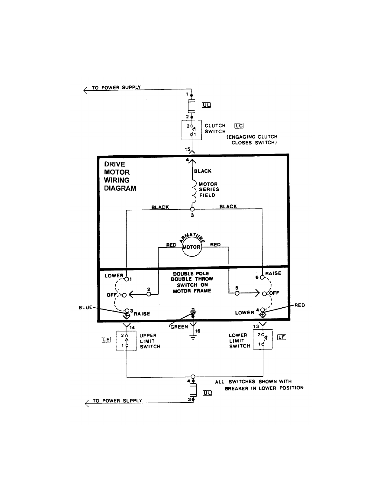
FIGURE 5
SCHEMATIC DIAGRAM
VERTICAL LIFT ELEVATING MECHANISM
DO NOT USE RAISE/LOWER SWITCH TO STOP & START MOTOR.
Page 16 GEH 6468A - Power/Vac VL Breaker
Page 17
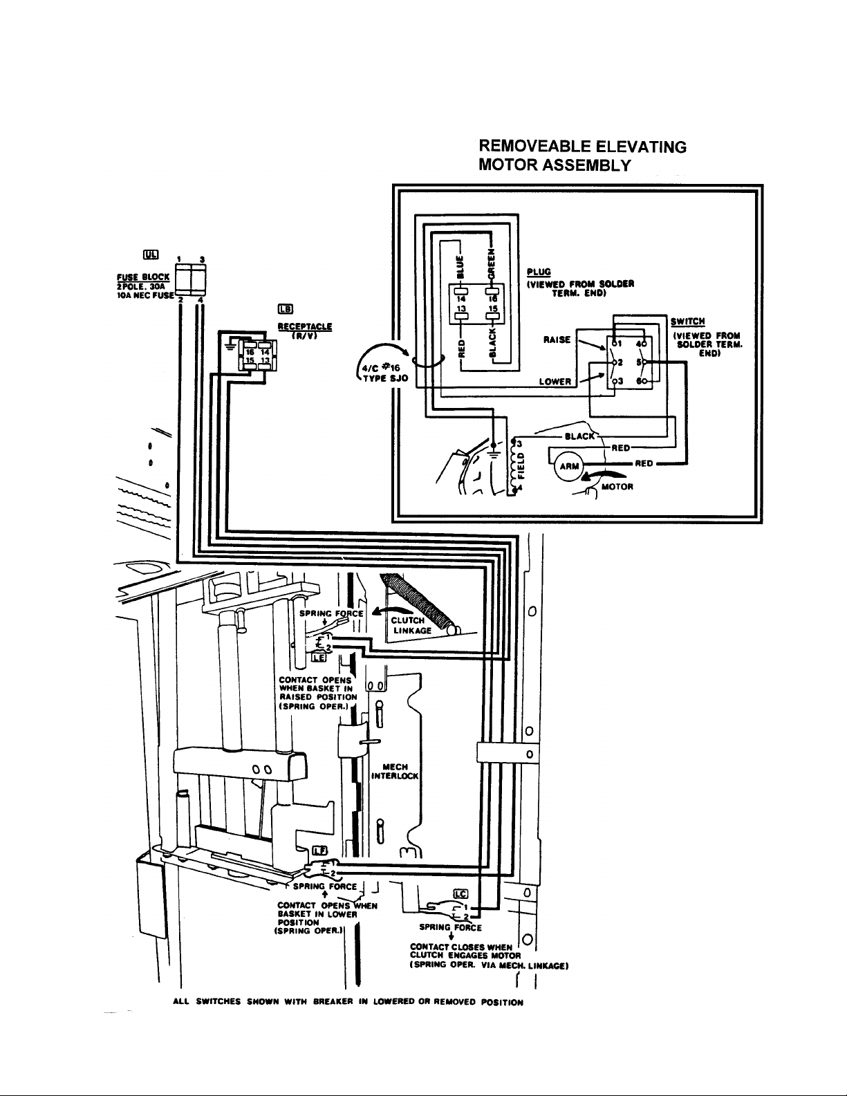
FIGURE 6
STATIONARY STRUCTURE WIRING
GEH 6468A - Power/Vac VL Breaker Page 17
Page 18
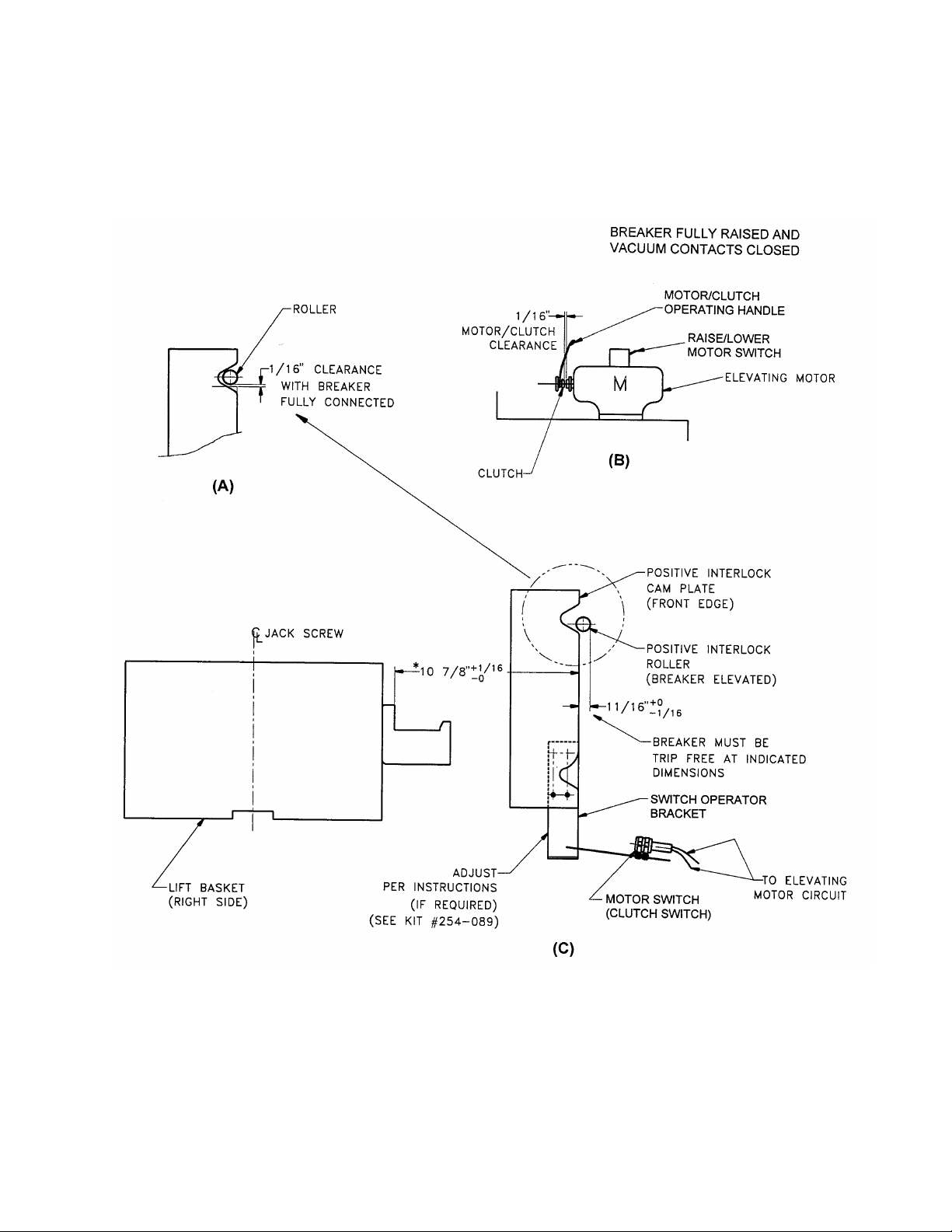
FIGURE 7
BY-PASS KIT INSTALLATION
Page 18 GEH 6468A - Power/Vac VL Breaker
Page 19
FIGURE 8
TYPICAL BREAKER WIRING DIAGRAM
(REPLACEMENT FOR BREAKERS WITH MS MECHANISMS)
GEH 6468A - Power/Vac VL Breaker Page 19
Page 20
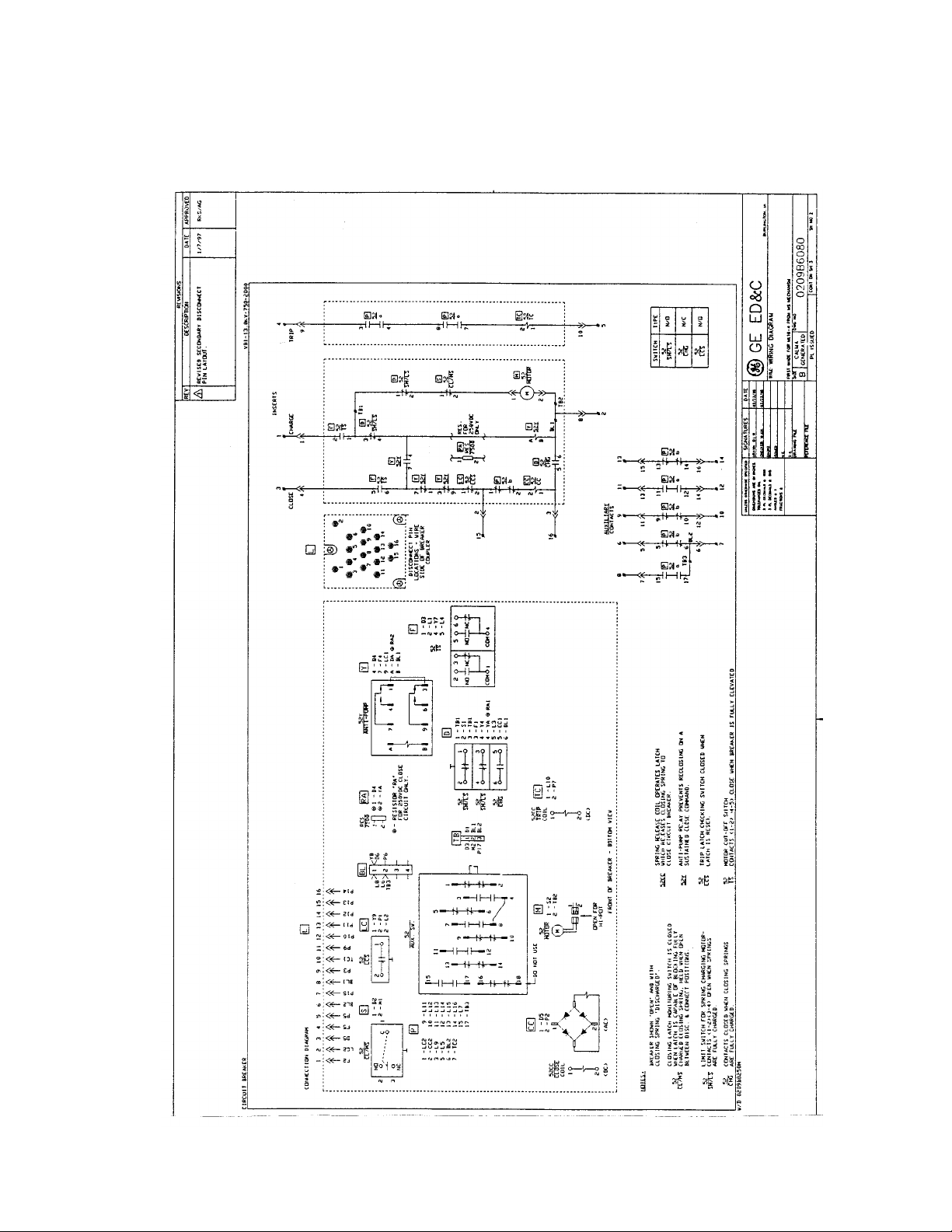
FIGURE 9
TYPICAL BREAKER WIRING DIAGRAM
(REPLACEMENT FOR BREAKERS WITH ML MECHANISMS)
Page 20 GEH 6468A - Power/Vac VL Breaker
Page 21

FIGURE 10
ADJUSTMENT OF PLUNGER INTERLOCK
Adjustment of plunger interlock - Breaker raised to connect position. Gap adjustment as a function
of breaker plunger travel to assure proper switch operation.
P G R
Plunger
Interlock
Travel
(To be
measured) Min. Max. Min. Max.
1-1/16 .001 1/16 1” 1-1/16
Gap between top of plunger interlock and
bottom of aux. switch rod
Resulting travel of the aux. switch rod
GEH 6468A - Power/Vac VL Breaker Page 21
Page 22
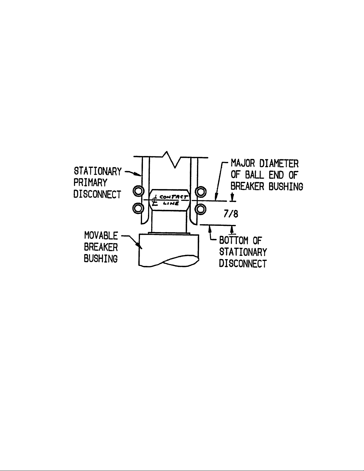
FIGURE 11
PRIMARY CONTACT PENETRATION
Page 22 GEH 6468A - Power/Vac VL Breaker
Page 23

FIGURE 12
POSITIVE INTERLOCK ROLLER
GEH 6468A - Power/Vac VL Breaker Page 23
Page 24

FIGURE 13
POSITIVE INTERLOCK 1000 MVA UNITS
Page 24 GEH 6468A - Power/Vac VL Breaker
Page 25

Page 26

Page 27

7. FEATURES
7.1. SAFETY PRECAUTIONS.
This circuit breaker uses powerful springs for
energy storage. DO NOT WORK ON THE
INTERRUPTERS OR THE MECHANISM UNLESS
THE CIRCUIT BREAKER IS IN THE "OPEN"
POSITION AND BOTH THE CLOSING AND
OPENING SPRINGS ARE EITHER DISCHARGED
OR GAGGED AND ALL ELECTRICAL POWER IS
REMOVED. These precautions are required to
prevent accidental operation. Anyone working on
the circuit breaker should be familiar with the
contents of this instruction book.
The circuit breaker has been shipped in the
CLOSED position. After removing packing
material, open the breaker by pushing in firmly on
the manual trip button (8, Fig. 16), while keeping
hands away from moving parts. Verify that the
operation counter advances one count.
Closing and opening springs are now in their
discharged positions. Check this by first pressing
the manual close button, then the manual trip
button. The indicator flags on the front of the
breaker should show "OPEN" and "DISCHGD". All
mechanical and electrical checks should be
completed before putting breakers in service.
their vertical positions, preventing the clutch
handle from being pulled forward and engaging the
elevating motor in the cubicle. The closed breaker
must be manually or electrically tripped open
before the clutch handle can connect the elevating
motor to the elevating mechanism, and allow the
breaker to be raised or lowered.
When the breaker is raised or lowered, the positive
interlock roller and lever are forced forward by the
positive interlock plate on the right side of the
frame and top plate. The interlock roller and lever
are held in this forward position during raising and
lowering operations, preventing the breaker from
being closed in any intermediate position between
the connect and the fully lowered position. An
attempt to close the breaker will cause the stored
energy springs to discharge without the breaker
contacts closing or moving. The breaker must be
fully connected (raised) and the clutch handle must
be released before the breaker can be closed.
Releasing the clutch handle allows the interlock
plate in the cell to move downward allowing the
interlock roller and lever to return to their normal
vertical positions. The breaker may then be
closed. When in the fully lowered position, the
breaker must be pulled forward 2-1/4” in the
cubicle and the test coupler installed to allow the
breaker to be closed electrically.
7.2. INTERLOCKS
Each PowerVac® VL vacuum circuit breaker is
provided with the following interlocks:
7.2.1. RATING INTERFERENCE PLATE
This interlock permits only a breaker with a
matching continuous current, voltage and
interrupting rating to be inserted into a metal-clad
compartment of identical rating. The rating
interference plate must be adjusted to match the
current rating of the compartment. This adjustment
is done by positioning a pin on the lower left side of
the breaker truck to align with the proper cubicle
interference plate.
7.2.2. POSITIVE INTERLOCK SYSTEM
The positive interlock system prevents connecting
or disconnecting the breaker when the breaker
vacuum contacts are closed.
This interlock feature is accomplished by a roller
and lever located on the interlock shaft, on the
right side of the breaker (Fig. 16 & 17). When the
breaker is closed, this roller and lever are locked
in
7.2.3. SPRING DISCHARGE SYSTEM
The spring discharge lever and pin, (Fig. 17) are
provided as a safety feature for operating
personnel, and to prevent closing the breaker in
the lowered position in the cell.
The spring discharge pin and lever operate in
conjunction with the spring discharge bracket
mounted in the front left side of the vertical frame
angle in the cubicle. The spring discharge pin rides
on the cam edge surfaces of the spring discharge
bracket, when the breaker is inserted into or
withdrawn horizontally from the cell.
If the breaker is outside the cell, and an operator
charges the stored energy mechanism, the spring
discharge bracket will lift the discharge pin and
discharge the stored energy springs, when the
breaker is pushed into the lowered position in the
cell. When the breaker is fully inserted into the
lowered position within the cell, the discharge pin is
held in an upward position by the spring discharge
bracket, and prevents the breaker from being
closed. Attempting to charge a breaker in this full
inward and lowered position will discharge
the
GEH 6468A - Power/Vac VL Breaker Page 27
Page 28

stored energy mechanism without closing the
breaker.
8. OPERATION
The PowerVac® VL vacuum circuit breaker uses a
sealed vacuum power interrupter to establish and
interrupt a primary circuit. Primary connections to
the associated metal-clad switchgear are made by
pole assemblies, electrically and mechanically
connected to the vacuum interrupters. Molded
supports, one per pole on a three pole breaker,
provide interchangeable mountings for the primary
poles, interrupters, and heat dissipation fins (where
used). The operating mechanism provides
horizontal motion at each pole location in order to
move the lower contact of the vacuum interrupters
from an open position to a spring-loaded closed
position and then back to the open position on
command.
The ML-18VL mechanism (Figs. 17 & 23) is the
stored-energy type and uses a gear motor to
charge a closing spring. During a closing operation,
the energy stored in the closing spring is used to
close the vacuum interrupter contacts, charge the
wipe springs which load the contacts, charge the
opening springs, and overcome bearing and other
frictional forces. The energy then stored in the wipe
and opening springs will open the contacts during
an opening operation.
Closing and opening operations are controlled
electrically by the control switch on the metal-clad
door or remote relaying. Mechanical control is
provided by manual close and trip buttons on the
circuit breaker.
The closing spring may be manually charged, and
a method for slow closing the primary contacts is
available when the circuit breaker is withdrawn
from the metal-clad cubicle. (See Section 10) The
mechanism will operate at the ac or dc voltage
indicated on the circuit breaker nameplate.
8.1. CLOSE SPRING CHARGING
Figure 23 shows a front view of the ML-18VL in a
schematic form. The primary contacts are open
and the closing spring is charged. The closing
spring charging system consists of a closing spring
(1, view B) mounted on the left side of the breaker
and the electrical charging system mounted on the
right side of the breaker. Both components are
fastened
to the cam shaft (2, view B). A manual charging
system (3, view A) is provided so that the
mechanism can be slow closed and the closing
spring can be charged if there is a loss of electrical
control power.
Spring charging is accomplished electrically by a
rotating eccentric on the output shaft of a gear
motor driving pivoted charging arms (4, view C).
The charging arms oscillate about the centerline of
a ratchet wheel (5, view C). A driving pawl (6, view
C), mounted within the charging arms, oscillates
with the charging arms. Starting from its rear-most
position, the charging arms rotate forward, while
spring forces engage the driving pawl with a tooth
on the ratchet wheel. The ratchet wheel is
advanced by the rotating charging arms and pawl
assembly. Advancement of one tooth spacing is
provided for each oscillation of the system. The
ratchet motion is restricted to one direction by a
spring-loaded holding pawl that prevents the
ratchet wheel from going backwards as the
charging arms oscillate back to pick up the next
tooth. Thirteen complete cycles of the charging
arms are needed for a full charge of the closing
spring.
The efficient, compact gear motor accomplishes
this action in about two seconds. When the
charging cycle is complete, the ratchet wheel is
positioned so that a missing tooth is adjacent to the
driving pawl and any motor overspin will not drive
the ratchet wheel, thus preventing damage to the
system.
When the spring is completely charged, the
assembly is retained in that position by the close
latch until it is desired to close the circuit breaker.
The closing coil cannot be electrically energized
unless the closing spring is completely charged.
This action is prevented by the 52/CHG switch in
the closing circuit.
The manual charging system (3, view A) works
directly on the cam shaft where a one-way clutch
(7, view A), driven by a manual handle, provides
rotation of the ratchet wheel. Manual pumping of
the handle advances the ratchet wheel and the
holding pawl prevents counter-rotation while the
handle is returning for another stroke. Approximately eight complete strokes of the manual
handle are required for one complete springcharging operation. When the spring charge
indicator (8, Fig. 17) shows "CHARGED", MANUAL
CHARGING MUST BE DISCONTINUED TO
AVOID MECH-ANISM DAMAGE.
Page 28 GEH 6468A - Power/Vac VL Breaker
Page 29

8.2. CLOSING OPERATION. (REFER TO FIG.
23)
By either energizing the close solenoid or
depressing the manual close button, the close latch
(8, view C) is rotated, releasing the closing spring
(1, view B). This action releases the energy in the
closing spring and transmits it to the closing cam
(9, view D) and closing roller (10, view D) causing
the linkage to rise until the close prop (11, view D)
can slip under the close roller (10, view D) and
hold the linkage in place. As the linkage moves,
the output crank (12, view D) rotates the cross
shaft (13, view D) which in turn rotates the phase
bell cranks (14, view E) on all three poles. The
rotation of the phase bell cranks compresses the
two opening springs (15, view E) on poles 1 and 3,
closes the vacuum interrupters, and compresses
the wipe springs (16, view E) on each pole. The
rotation of the cross shaft (13, view D) also
changes the auxiliary switch (7, view D) position.
The position flag on the front panel will then
indicate "CLOSED". After the breaker is closed, the
charging motor is again energized and the closing
spring is charged as described under "CLOSE
SPRING CHARGING". Spring charging is possible
when the breaker is in the closed position because
the linkage is held in place by the prop.
8.3. OPENING OPERATION. (REFER TO FIG.
23)
By either energizing the trip solenoid (18, view B)
or depressing the manual trip button (23, view B),
the trip latch (19, view D) is rotated, permitting the
linkage to collapse. The vacuum interrupter
contacts will then open under the force of the wipe
springs (16, view E) and opening springs (15, view
E). At the end of the opening stroke, the center
phase wipe spring assembly hits a stop on the
frame limiting overtravel and rebound. Rotation of
the cross shaft from the closed to the open position
operates the auxiliary switch (17, view D) opening
the trip coil circuit. When the closing spring has
been recharged, the linkage is reset allowing the
trip latch to rest in place on the trip roller, ready for
another closing operation.
on the closing stroke. Electrically energizing the
trip coil while closing will, after the auxiliary switch
contacts change position, rotate the trip latch and
permit the circuit breaker to open fully. The linkage
will reset as in a normal open operation and the
closing spring will recharge as described under
"CLOSE SPRING CHARGING".
9. CONTROL CIRCUIT
A typical PowerVac® VL circuit breaker ML-18VL
mechanism wiring diagram is shown in Fig. 8 and
9. Check the wiring diagram supplied with the
actual circuit breaker for its wiring.
The close spring charging motor circuit is
established through the Close Latch Monitor Switch
(CL/MS) if the close latch is reset and the Spring
Motor Limit Switch (SM/LS) if the closing spring is
discharged. When the closing spring is charged,
the SM/LS interrupts the circuit.
The close coil circuit is established through two
normally closed 52Y relay contacts, and the Latch
Checking Switch (LCS), if the trip latch is reset. An
auxiliary switch contact 52B is also in series with
the close coil and closes when the breaker is open
and opens when the breaker is closed. During a
close operation, cam rotation closes the SM/LS
contact allowing the 52Y relay to be energized. The
52Y relay opens its contacts, in the close coil
circuit and seals itself in through one of its own
contacts. This seal-in action prevents reclosing on
a sustained close command. The close signal must
be removed to drop out the 52Y relay and
reestablish the closing circuit. This provids an antipump feature.
Circuit breaker-mounted auxiliary switch contacts
not used in the control circuit are brought out for
control and indication functions. The metal-clad
equipment may provide a breaker-operated
stationary auxiliary switch for additional contacts.
10. MECHANICAL CHECKING AND SLOW
CLOSING
If the closing spring has not been recharged, the
trip latch will be held out of position. A latchchecking switch (LCS) (21, view C) will not close
unless the latch is in its normal position. The
contacts of the latch-checking switch are part of
the closing circuit and will not allow for an electrical
close until the latch is reset.
8.4. TRIP FREE OPERATION.
The linkage is mechanically trip-free in any
10.1. VISUAL INSPECTION
Visually inspect the circuit breaker for any signs of
damage or loose hardware.
10.2. CLOSING SPRING CHARGING
Manually charge the breaker closing spring using
the charging handle provided (1, Fig. 18). The
closing spring is charged by a ratcheting
mech-
location
GEH 6468A - Power/Vac VL Breaker Page 29
Page 30

anism that advances one ratchet tooth at a time.
When the spring is fully charged, the spring load is
held by the closing latch. The spring indicator (6,
Fig. 16) changes from "DISCHGD" to "CHARGED',
and a positive snap is be heard as the spring
travels over center.
CAUTION: AFTER THE SPRING IS COMPLETELY CHARGED, AS INDICATED ABOVE,
FURTHER FORCING THE CHARGING HANDLE
MAY CAUSE DAMAGE TO THE CLOSING
LATCH AND ITS ASSOCIATED PARTS.
10.3. CLOSING SPRING GAG
Removing the mechanism cover and inserting the
tip of the closing spring gag tool (3, Fig. 19)
between the end of the spring and the spring guide,
engaging the détentes on the gag tool into the slots
in the closing spring guide.
With the gag tool in position depress the manual
close button. This action will partially discharge the
closing spring and also partially close the vacuum
interrupter contacts. Do not energize the secondary
control circuit at this time.
CAUTION: USE OF THE GAG TOOL SHOULD
ONLY BE ATTEMPTED WHEN THE BREAKER IS
OUT OF THE CUBICLE.
10.4. SLOW CLOSING
To manually slow close the breaker contacts,
install the closing spring gag, as described above.
Put the manual charge handle on the manual
charge lever and move the handle up and down.
The breaker will be fully closed when the spring
charge indicator shows "CHARGED"
CAUTION: WITH THE GAG TOOL INSTALLED,
THE BREAKER CLOSED, AND OPENING
SPRINGS CHARGED, THE BREAKER CAN BE
TRIPPED AT FULL SPEED.
10.5. GAG TOOL REMOVAL
To remove the gag tool, the closing spring must be
fully charged. If the spring charge indicator does
not show "CHARGED" in the window, manually
charge the spring until it does. Lift up and push in
on the gag tool to clear the détentes on the gag
tool from the slots in the closing spring guide.
While holding the gag tool up, remove it from the
opening. Close the gag hole cover. For safety, first
close the breaker by depressing the manual
"CLOSE" button and then depress the manual
"TRIP" button. All stored energy is now removed
from the breaker.
11. DIMENSIONAL CHECKS
With the breaker closed and the gag tool installed,
remove the front portion of the breaker top plate
before performing the following dimensional
checks:
11.1. PRIMARY CONTACT EROSION
In the closed position, the erosion disk (5, Fig. 21),
located below the operating rod insulator, is
aligned with a reference arm (4, Fig. 21) on new
interrupters. As contact erosion occurs, the erosion
disk will move upward from alignment with that
reference arm. When erosion reaches 1/8 inch, the
POWER/VAC VL interrupters should be replaced.
DO NOT READJUST THE ALIGNMENT OF THE
EROSION INDICATOR ARM EXCEPT WHEN
INSTALLING A NEW VACUUM INTERRUPTER.
11.2. SPRING WIPE
With the breaker closed and the closing spring
gagged, measure with a feeler gauge and record
the distance between the top of the wipe indicator
and the bottom of the erosion disk for each phase
(see Figure 33 Dimension W). Trip the breaker with
the closing spring gag tool still installed and
measure and record the distance between the wipe
indicator and erosion disk. Subtract the closed
position measurement from the open position
measurement. The result is the amount of wipe on
each individual pole. The wipe is to be greater than
0.075 inch. Adjustment is not required until wipe is
0.075 inch or less. If adjustment is required see
WIPE ADJUSTMENT in MECHANICAL ADJUSTMENTS section.
The ML-18VL mechanism is furnished with very
low gradient wipe springs so that adjustment is not
a precision operation and considerable loss of wipe
can be tolerated without affecting performance.
11.3. CONTACT GAP
The method of measuring the contact gap is as
follows: With the breaker in the open position, the
closing springs charged, and the closing spring gag
tool installed, apply a piece of masking tape to the
surface of the operating rod insulator as shown in
Figure 27. Using a reference block, make a mark
on the tape near the top on all three poles. It is also
advisable to put a reference mark on the tape to
identify to which pole the tape is applied. Remove
the closing spring gag tool and close the breaker.
Using the same procedure as above, re-mark the
tape. This new mark will be near the bottom of the
tape. Trip the breaker, remove the tapes and reapply them to a flat surface. Measure the distance
between the two lines. A caliper will give an
accurate reading of the contact gap, Dimension G.
Page 30 GEH 6468A - Power/Vac VL Breaker
Page 31

The gaps must be between the 0.60 inch
maximum for the center phase and 0.54 inch
minimum for all phases. It is not necessary that all
readings correspond. A properly adjusted breaker
often has more gap and wipe on the center pole
than on the outside poles.
CAUTION: DO NOT ALLOW ANYTHING TO
COME IN CONTACT WITH THE INTERLOCK
ROLLER ON THE RIGHT SIDE OF THE
MECHANISM, OR THE SPRING DISCHARGE
PIN ON THE LEFT SIDE OF THE MECHANISM.
11.4. CLOSE COIL PLUNGER GAP
12. ELECTRICAL CHECKS
12.1. ELECTRICAL OPERATION
To check the electrical operation, attach a
secondary test coupler to the circuit breaker
connector. Check the control voltage on the
nameplate and close and open the breaker several
times.
CAUTION: REPEATED OPERATIONS AT A
RATE EXCEEDING TWO PER MINUTE MAY
CAUSE CHARGING MOTOR OVERHEATING
AND FAILURE.
The close coil plunger gap is shown in Figure 30.
With the closing spring discharged, operate the
plunger to make certain that the plunger moves
freely over its full stroke in the coil. To check the
closing coil plunger gap the breaker should be
open and the closing spring charged and gagged.
Dimension C is obtained by depressing the close
plunger button until resistance is felt. The gap
between the plunger button and the coil housing
should be between 0.35 and 0.40 of an inch.
11.5. TRIP COIL PLUNGER GAP
The trip coil plunger gap is shown in Figure 32.
With the breaker in the open position and the
closing spring in the charged position, make certain
that the trip linkage and trip shaft move freely over
the full plunger travel. To check the trip coil
plunger gap adjustment, the breaker is to be closed
with the closing spring discharged. Dimension T
between the plunger button and the coil housing
should be between 0.20 and 0.25 inch. This
dimension is obtained when the trip plunger button
is depressed until resistance is felt. If the breaker is
equipped with an optional second trip coil, use
same procedure.
11.6. CONTROL SWITCH ADJUSTMENT
Leave the circuit breaker in an open and spring
discharged condition after checks are complete
and refer to metal-clad instruction book GEH1802X before inserting the circuit breaker into a
metal-clad unit. Reinstall the front cover if it has
been removed.
12.2. HIGH-POTENTIAL TEST
If high potential tests to check the integrity of the
insulation are required, the AC high potential test
described below is strongly recommended. DC
high potential testing is not recommended. The
following procedure must be adhered to.
CAUTION: IF DC HIGH POTENTIAL TESTING IS
REQUIRED, THE DC HIGH POTENTIAL
MACHINE MUST NOT PRODUCE PEAK
VOLTAGES EXCEEDING 50 kV.
12.2.1. PRIMARY CIRCUIT
Electrical checking consists of electrical breaker
operation, primary and secondary wiring highpotential testing (if required), primary circuit
resistance (if required), POWER/VAC interrupter
high-potential testing, and insulation resistance to
ground.
The breaker is to be in the open position with the
opening and closing springs discharged. This
results in the control switch plungers being in the
depressed position. The switches to be checked
are shown in Figure 31. On the LCS and stacked
switches (SM/LS & CHG), the plunger rod is to be
recessed within the rear of the switch body. The
recess should measure between 0 and 1/32 inch.
This is a visual check. The CL/MS switch with
The breaker should be hipotted in the closed
breaker mode. An AC hipot machine capable of
producing the test voltages shown below may be
used to hipot the breaker phase to phase and
phase to ground.
BREAKER VOLTAGE TEST VOLTAGE
4.16 kV 14 kV
7.2 kV 27 kV
13.8 kV 27 kV
wiring terminals on the side is to be adjusted as
described above. For the CL/MS switch with wiring
terminals on the rear, the plunger is set to 0.99 to
1.01" from its mounting bracket.
The machine should be connected with its output
potential at zero and the voltage increased at
500
GEH 6468A - Power/Vac VL Breaker Page 31
Page 32

vps to the test voltage and that voltage maintained
for 60 seconds. The voltage should then be returned
to zero and the hipot machine removed from the
circuit. Do not exceed the test voltage indicated for
the applicable breaker voltage rating.
12.2.2. SECONDARY CIRCUIT
Prior to hipotting the breaker secondary circuit,
disconnect the motor leads and thread a wire
connecting all secondary coupler pins. Increase the
voltage to 1125 volts (rms) 60 Hz and maintain for 60
seconds. Reduce the voltage to zero and remove the
hipot machine from the circuit. Remove the wire
connecting the secondary coupler pins and reconnect
the motor leads.
12.3. PRIMARY CIRCUIT RESISTANCE
A resistance check of the primary circuit may be
made with the breaker closed. Use a low resistance
measuring instrument which measures micro-ohms.
The 100 ampere reading should be 5 to 25 microohms for a 3000 amp breaker, 25 to 50 micro-ohms
for a 2000 amp breaker and 30 to 60 micro-ohms for
a 1200 amp breaker when connected across the
primary and secondary stabs on the breaker.
12.4. VACUUM INTERRUPTER INTEGRITY
TEST
A vacuum integrity test is performed using an AC
high potential tester. A vacuum integrity test of the
inter-rupter is required to insure that no loss of
vacuum has occurred. With the breaker open,
individually check each interrupter by connecting the
hi-pot machine “Hot,” lead to the primary bushing and
the ground lead to the load side bushing. If the
machine has a center point ground, the connections
can be made either way. Apply 36 kV (rms) 60 Hz at
500 vps and hold for 10 seconds. If no breakdown
occurs, the interrupter is in acceptable condition.
After the high potential volt-age is removed,
discharge any electrical charge that may be present
through the internal ground of the test machine or by
a grounded cable to one of the phase bushing.
If a failure of a vacuum bottle should occur during the
integrity test, the test procedure should be reviewed
and the pole piece cleaned. GE failure rate for
vacuum bottles is 0.0007 per field unit. Note the
voltage level at failure on the first test, and retest the
phase pole piece. If the pole piece passes test, the
vacuum bottle is acceptable STOP.
If the test fails again but at a higher voltage level
than was observed in the first test, clean the pole
piece and retest. If a failure of the integrity test
occurs a third time, consider the vacuum bottle to
have lost vacuum and replace the complete pole
piece as described under Repair of Interrupter
Assembly
CAUTION: X-RADIATION WILL BE
PRODUCED IF AN ABNORMALLY HIGH VOLTAGE
IS APPLIED ACROSS A PAIR OF ELECTRODES IN
A VACUUM. X-RADIATION WILL INCREASE AS
VOLTAGE INCREASES AND/OR AS CONTACT
SEPARATION DECREASES. ONLY TEST A
CORRECTLY-AD-JUSTED CIRCUIT BREAKER.
DURING A HIGH POTENTIAL OR A VACUUM
INTEGRITY TEST, ANY X-RADIATION WHICH MAY
BE PRODUCED WILL NOT BE HAZARDOUS AT A
DISTANCE SAFE FOR HIGH POTENTIAL
TESTING, IF THE TEST IS CONDUCTED AT THE
REC-OMMENDED VOLTAGE AND WITH THE
NORMAL OPEN CIRCUIT BREAKER GAP.
DO NOT APPLY VOLTAGE THAT IS HIGHER THAN
THE RECOMMENDED VALUE. DO NOT USE
CONTACT SEPARATION THAT IS LESS THAN
THE RECOMMENDED OPEN-POSITION BREAKER
CONTACT GAP.
This test of the vacuum interrupter will determine its
internal dielectric condition and vacuum integrity.
Although a AC high potential test is recommended for
Checking the vacuum integrity, a DC high potential
test can also be conducted on the vacuum
interrupters at 50 kV and held for 10 seconds with the
restrictions noted as follows.
No attempt should be made to try to compare the one
vacuum interrupter with another nor to correlate the
condition of any interrupter to low values of DC
leakage current. There is no significant correlation.
After the high potential voltage is removed, discharge
any electrical charge that may be retained.
CAUTION: MANY DC HIGH POTENTIAL MACHINES ARE HALFWAVE RECTIFIERS. THIS
TYPE OF HIPOT TESTER MUST NOT BE USED
TO TEST VACUUM INTERRUPTERS. THE
CAPAC-ITANCE OF THE POWER/VAC BOTTLES
IS VERY LOW AND THE LEAKAGE IN THE
RECTIFIER AND ITS DC VOLTAGE MEASURING
EQUIPMENT IS SUCH THAT THE PULSE FROM
THE HALFWAVE RECTIFIER MAY BE IN THE
NEIGHBORHOOD OF 120 Kv WHEN THE
METER IS ACTUALLY READ-
Page 32 GEH 6468A - Power/Vac VL Breaker
Page 33

ING 40 kV. IN THIS CASE, SOME PERFECTLY
GOOD BOTTLES CAN SHOW A RELATIVELY
HIGH LEAKAGE CUR-RENT SINCE IT IS THE
PEAK VOLTAGE OF 120 kV THAT IS
PRODUCING ERRONEOUS BOTTLE LEAKAGE
CURRENT. IN ADDITION, ABNORMAL XRADIATION WILL BE PRODUCED.
the cubicle and connecting the breaker test coupler
accessory set (optional). The breaker functions
may now be checked electrically or manually via
the breaker control switch on the switchgear unit,
or the manual push buttons on the breaker front.
14. MAINTENANCE
An acceptable AC high potential machine is available from: GE Company, Burlington, Iowa, Catalog
Number 282A2610P001. The following machines
are also acceptable.
AC machines: Hipotronics Model 7BT 60A
Hipotronics Model 60HVT
Biddle Cat. 222060
Phoenix Model 7BT 60A
DC machines: Hipotronics Model 860PL
Hipotronics Model 880PL
12.5. INSULATION TESTS
The primary circuit insulation on the breaker may
be checked phase to phase and phase to ground
using a 2500 Volt or other suitable megohmeter.
Since definite limits cannot be given for
satisfactory insulation values, a record should be
kept of the megohmeter readings as well as
temperature and humidity readings. This record
should be used to detect any weakening of the
insulation from one check period to the next.
Generally, readings should equal or exceed 10,000
megohms.
To measure the breaker secondary circuit
insulation resistance, disconnect the motor leads
and thread a wire connecting together all
secondary coupler pins. The measurement is made
by connecting a 500 Volt megohmeter from the
wire to ground.
13. CHECKING AND INSTALLING BREAKERS
Roll the PV-VL breaker into the cell (frame & top
plate). If the breaker stored energy springs were
charged, the spring discharge lever, located on the
left side of the breaker, will be actuated by the
spring discharge bracket and discharge the stored
energy springs, (closing and opening springs). The
yellow semaphore on the front of the breaker will
indicate “DISCHGD”.
The breaker cannot be closed when it is fully
inserted into the cell, in the lowered position.
The breaker may be operated electrically when in
the lowered position by completely removing it
from
14.1. GENERAL
POWER/VAC VL circuit breakers have been
designed to be as maintenance-free as practicable.
They include features such as sealed vacuum
interrupters and long-life synthetic greases which
contribute to many years of trouble-free performance with a minimum amount of maintenance.
If maintenance on the PowerVac® VL breaker is
being performed to an extended schedule such as
a 5-year or 10-year program, the vacuum
inter-rupter integrity test should be performed if the
breaker is removed for reasons other than
scheduled breaker maintenance, and it has been
more than one year since the last vacuum integrity
test, a test should be performed.
Both long and short term maintenance of all
electrical equipment is essential for reliability and
safety. Maintenance programs MUST be customized to the specific application, well planned, and
carried out consistent with both industry experience
and manufacturer’s recommendations. Local environment must always be considered in such
programs, including such variables as ambient
temperatures, extreme moisture, number of
operations, corrosive atmosphere or major insect
problems and any other unusual or abusive
condition of the application.
One of the critical service activities, sometimes
neglected, involves the servicing and calibration of
various control devices. These devices monitor
conditions in the primary and secondary circuits,
sometimes initiating emergency corrective action
such as opening or closing circuit breakers. In view
of the vital role of these devices, it is important that
a periodic test program be followed. As was
outlined above, it is recognized that the interval
between periodic checks will vary depending upon
environment, the type of device and the user’s
experience. It is the General Electric recommendation that, until the user has accumulated
enough experience to select a test interval better
suited to his individual requirements, all significant
calibrations should be checked at an interval of
one to two years.
GEH 6468A - Power/Vac VL Breaker Page 33
Page 34

To accomplish this, protective relays can be
adequately tested using field test sets. Specific
calibration instructions on particular devices
typically are provided by supplied instruction
books.
Instruction books supplied by manufacturers
address components that would normally require
service or maintenance during the useful life of the
equipment. However, they can not include every
possible part that could require attention,
particularly over a very long service period or
under adverse environments. Maintenance
personnel must be alert to deterioration of any part
of the supplied switchgear, taking actions, as
necessary, to restore it to serviceable status.
ognized the need for a common trouble reporting
format. A reproducible copy of this form is included
on pages 67 and 68 of this book and is
recommended for use with any manufacturer's
circuit breakers. Forward completed forms to GE at
Burlington Iowa.
The intent is for each maintenance organization to
keep specific problem files with this information
documented. If the problem is serious or repetitive,
a summary should be sent to the appropriate
manufacturer for action. The level of detail
included on the form is considered very desirable
so that the manufacturer's investigator may more
thoroughly understand and solve the reported
problem.
Industry publications of recommended
maintenance practices such as ANSI/NFPA 70B,
Electrical Equipment Maintenance, should be
carefully studied and applied in each user’s
formation of planned maintenance.
14.2. SERVICE CONDITIONS
The frequency of required maintenance depends
on the severity of the service conditions of the
switch-gear application. If the service conditions
are mild, the interval between maintenance
Some users may require additional assistance from
GE in the planning and performance of
maintenance. GE can be contacted to either
undertake maintenance or to provide technical
assistance such as the latest publications.
The performance and safety of this equipment may
be compromised by the modification of supplied
parts or their replacement by non-identical
substitutes. All such design changes should be
qualified by GE factory engineering.
The user should methodically keep written
maintenance records as an aid in future service
planning and equipment reliability improvement.
Unusual experiences should be promptly communicated to GE.
POWER/VAC® INTERRUPTER
The POWER/VAC interrupter used in this breaker
is a reliable, clean interrupting element. Since the
contacts are contained in a vacuum chamber, they
remain clean and require no maintenance at any
time. The metallic vapors eroded from the contact
surfaces during high current interruption remain in
the chamber and are deposited on metal shields
thus insuring a high dielectric value of the vacuum
and the walls of the interrupter.
operations may be extended to 10 years or 10,000
no load or 5000 for normal load switching
operations.
Mild service conditions are defined as an
environment in which the switchgear is protected
from the deleterious effects of conditions such as:
Salt spray.
Changes in temperature that produce
condensation, conductive and/or abrasive
dust.
Damaging chemicals and fumes.
Vibration or mechanical shock.
High relative humidity (90%).
Temperature extremes (below -30º C or above
+40º C).
WARNING: BEFORE ANY MAINTENANCE
WORK IS PERFORMED, MAKE CERTAIN THAT
ALL CONTROL CIRCUITS ARE DE-ENERGIZED
AND THAT THE BREAKER IS REMOVED FROM
THE METALCLAD UNIT. DO NOT WORK ON
THE BREAKER OR MECHANISM WHILE IT IS IN
THE CLOSED POSITION WITHOUT TAKING
PRECAUTIONS TO PREVENT ACCIDENTAL
TRIPPING. DO NOT WORK ON THE BREAKER
WHILE THE CLOSING SPRING IS CHARGED
UNLESS IT IS SECURED IN THAT POSITION BY
THE CLOSING-SPRING GAG.
TROUBLE REPORTING
Although all reputable manufacturers design their
products to perform satisfactorily with a minimum
of problems, the IEEE Switchgear Committee, an
organization of both users and manufacturers, rec-
14.3. FAULT INTERRUPTIONS
The erosion rate of the primary contacts in the
vacuum interrupters is very low for no-load and
normal load switching operations. However, fault
current interruptions at or near the breaker rating
may result in appreciable contact erosion. With
frequent fault interruptions it is necessary to
Page 34 GEH 6468A - Power/Vac VL Breaker
Page 35

form maintenance based on the number of
interruptions. After each 15 full fault interruptions the
following should be performed:
1. Contact erosion check.
2. Wipe and gap check.
3. Vacuum interrupter integrity test.
14.4. CONTACT EROSION
Check in the breaker-closed condition per PRIMARY
CONTACT EROSION section 11.1. When erosion
reaches 1/8 inch, the interrupter should be replaced.
14.5. TRANSFER FINGER WEAR
With breaker open, examine the moving contact rod
projecting below the transfer fingers (10, Fig. 22).
Wipe off the lubricant in order to see the metal
surface condition. The finger locations should present
a burnished silver contact without copper appearance
at more than one location. If copper is visible at more
than one location per pole or the silver plating is torn,
the interrupter assembly should be replaced.
Relubricate with grease, part # 0282A2048P009
(mobil 28 red grease).
14.6. MECHANISM
Check all items covered in INSTALLATION and
readjust or tighten hardware as required. Lubricate as
recommended under LUBRICATION.
14.7. PRIMARY INSULATION PARTS
Using dry, non-linting cloth or industrial-type wipers,
clean accessible insulation surfaces on the interrupter
supports and operating rod insulators. In service
locations where contamination is heavy or external
flashovers, have occurred during interrupter highpotential testing, remove the interrupter assemblies
per the procedure in REPAIR AND REPLACEMENT
and clean the inside surfaces of the interrupter
supports and the outer insulation surfaces of the
POWER/VAC interrupters.
some locations. These bearings do not require
lubrication to maintain low friction, but lubrication
does not harm them and oiling lightly is
recommended. Sleeve bearings are used in some
linkage locations and needle or roller bearings are
used for low friction on trip shaft and close shaft.
Bearings are lubricated during factory assembly with
grease and oil, but all lubricants have a tendency to
deteriorate with age. Providing a fresh lubricant
supply at periodic intervals is essential to proper
breaker operation, especially where frequent
operation may have forced lubricant out of the
bearing
surfaces. Apply a few drops of light
synthetic machine oil such as Mobil 1 at each
bearing. Apply a coat of 0282A2048P009 grease on
the four corners of the closing spring guide where it
enters inside the spring. Metal-to-metal contact
surfaces should be cleaned and lubricated with
0282A2048P009 grease to provide cleanliness and
prevent oxidation.
Electrical primary contact surfaces also require
periodic lubrication to inhibit oxidation and minimize
friction. At each inspection and maintenance interval,
do the following:
1) Wipe clean and coat lightly with 0282A2048P009
grease all silvered primary contact surfaces such as
the movable contact rod of the interrupter and the
primary disconnect fingers.
2) Clean and coat lightly with 0282A2048P009 grease
the pins of the secondary coupler.
14.9. RECOMMENDED MAINTENANCE
The following operations should be performed at
each maintenance check:
1. Perform a visual inspection of the breaker. Check
for loose or damaged parts.
2. Perform slow closing operation described under
MECHANICAL CHECKING AND SLOW CLOSING.
Be sure to discharge the interrupter midband ring
before removing the interrupter assemblies. Removal
and reassembly of interrupter assemblies will
normally not require adjustment due to the design of
the interrupter operating rod insulator connection.
They should be returned to the same location from
which they were removed.
14.8. LUBRICATION
Proper lubrication is important for maintaining reliable
circuit breaker performance. The ML-18VL mechanism uses bearings which have a synthetic lining in
3. Check the erosion indicator and the wipe and gap
as described under DIMENSIONAL CHECKS.
4. Perform the vacuum interrupter integrity test as
described under ELECTRICAL CHECKS.
5. Lubricate the breaker operating mechanism as
described under LUBRICATION.
6. Check the electrical operation using the test
cabinet.
GEH 6468A -Power/Vac VL Breaker Page 35
Page 36

CAUTION: REPEATED OPERATIONS AT A RATE
EXCEEDING TWO PER MINUTE MAY CAUSE
CHARGING MOTOR OVERHEATING AND
SUBSEQUENT MOTOR FAILURE.
7. Examine the movable contact rod of the vacuum
interrupter. With the breaker open, wipe the lubricant
off the rod and examine the silver surface. The rod
should have a burnished appearance without copper
appearing through the silver. If copper is visible at
more than one location per pole, or if the silver
plating is torn, the interrupter assembly should be
replaced. Relubricate breaker movable contact rod
with 0282A2048P009 grease.
8. If desired, perform the additional tests (Megger,
Primary and Secondary High Potential, and Primary
Circuit Resistance). See ELECTRICAL CHECKS.
15. TIMING
Timing and speed checks are optional and also
depend on the level of maintenance performed.
Generally these tests are not required for normal
maintenance. If a new mechanism has been installed
or extensive repair, replacement or major
disassembly has been performed, it is recommended
that these tests be performed.
16. OPENING AND CLOSING SPEED
The opening speed is modified by moving the speed
adjusting nuts on the opening spring assemblies. A
change in the opening speed affects the closing
speed Reference Figure 29.
The operatingspeeds for 5 cycle breakers are as
follows:
Operation Feet Per Second
Open 5.0 normal, 4.5 minimum
Close 3.5 nominal, 4.0 maximum
17. REPAIR AND REPLACEMENT
17.1.GENERAL
The following information covers in detail the proper
method of removing various parts of the breaker in
order to make any necessary repairs. This section
includes only those repairs that can be made at the
installation site, or parts of the breaker that are most
subject to damage.
Important: Upon completion of any kind of repair
work, all interrupter and mechanism adjustments
must be checked.
Refer as needed to sections on mechanical and
electrical adjustments.
To determine contact velocity, a travel recorder and
oscillograph are required. Optional travel recorders
can be obtained through your local GE Sales Office
by ordering part number 0144Dl235G001. A typical
travel trace and interpretation are shown in Fig. 29.
Timing may be checked by monitoring control circuit
voltage and using no more than six volts DC and one
ampere through the vacuum interrupter contact to
indicate closed or open condition. Typical time
ranges vary with coil voltage, but nominal values are:
Initiation of trip signal to contact parting
32-45 Milliseconds
2 Milliseconds maximum pole spread
Initiation of close signal to contact closing
35-75 Milliseconds
2 Milliseconds maximum pole spread.
Trip-free operation may be checked by applying a
simultaneous close and trip signal, and a minimum
reclose operation may be checked by tripping a
charged breaker open while maintaining a close
signal.
Instantaneous reclose time 85-150 Milliseconds.
*Time from application of trip signal until
breaker contacts reclose.
17.2. REPLACEMENT OF INTERRUPTER
ASSEMBLIES
Interrupter are supplied in complete interrupter
assemblies which include the vacuum interrupter
mounted in the interrupter support, the primary studs
and disconnect fingers.
CAUTION: DO NOT ATTEMPT TO REMOVE OR
REINSERT THE VACUUM INTERRUPTER IN THE
INTERRUPTER SUPPORT ASSEMBLY. SPECIAL
TOLLS AVAILABLE ONLY AT THE FACTORY ARE
REQUIRED.
1 . Remove the front portion of the breaker top plate.
Close the breaker and remove the coupling clamp,
(8, Fig. 22). Hold hex projection (6, Fig. 22) at the
bottom of the operating rod insulator with a 1 inch
wrench and loosen the adjacent lock nut with a 3/4
inch wrench. Screw down the lock nut and the
operating rod insulator until clear of interrupter rod.
Remove the four bolts holding the pole assembly to
the mechanism and remove the old pole assembly.
2. Set the new pole assembly in place and install the
four mounting bolts. Set the pole assembly so that
the distance between the primary studs and the studs
on the adjacent pole are ten (10) inches center line to
center line.
Page 36 GEH 6468A - Power/Vac VL Breaker
Page 37

Page 38

shaft, or loosen clamping bolt in operating link.
Observe and make note of the direction of the
index mark on the end of the shaft and the position
of the operating link in relation to the stop screw.
Remove mounting hardware securing auxiliary
switch to mechanism plate. Slide auxiliary switch
and shaft out of operating link. Before removing
any wires from switch terminals, make sure they
are properly tagged with switch terminal numbers
to assure proper placement on new switch.
Remove wires.
To install new switch, attach leads then install
switch, or install switch then attach leads
depending upon type of switch and its terminal
accessibility. Install switch shaft in operating link
with index mark aligned as noted above. Reverse
above procedure to complete installation.
17.9. MOTOR REPLACEMENT
With the breaker open and the closing spring
discharged, remove auxiliary switch as described
above but do not disconnect leads. Move switch
toward side of mechanism far enough to clear
motor and tie there temporarily. Disconnect motor
leads. Remove the long bolt and spacer securing
the motor to the mechanism mid-plate. Remove
the two socket head cap screws securing the motor
to the mechanism top plate using a 5/16" Allen
socket and a 24" extension. Disengage the motor
output shaft from the charge linkage arms and
withdraw motor.
To install the new motor, reverse the above
procedure.
17.10. "Y" RELAY REPLACEMENT
Before removing the "Y" relay, make sure all leads
are marked with terminal locations. Next,
disconnect all leads and remove the two fasteners
securing the "Y" relay's shock absorbing mounting
bracket to the mechanism rear plate. Withdraw
relay and bracket. Remove fasteners securing
relay to mounting bracket.
the service and the time required to secure
replacements.
Renewal parts which are furnished may not be
identical to the original parts, but they will be
interchangeable.
A separate Renewal Parts Bulletin may be
available from your local GE Sales office.
18.1. ORDERING INSTRUCTIONS
1. Always specify the complete nameplate date of
both the breaker and the mechanism.
2. Specify the quantity, catalog number (if listed),
reference number (if listed), and description of
each part ordered, and the parts bulletin number.
3. Standard hardware, such as screws, bolts, nuts,
washers, etc. are not listed in this bulletin. Such
items should be purchased locally.
4. For prices or information on parts not listed in
the Renewal Parts Bulletin, refer to the nearest GE
office.
19. MECHANICAL ADJUSTMENTS
19.1 GENERAL
The ML-18VL Mechanism has been designed for
extended intervals between maintenance. In most
cases only the wipe and gap adjustments will
require re-setting throughout the life of the circuit
breaker.
19.2. WIPE ADJUSTMENT
Wipe is the additional compression of a preloaded
spring, used to apply force to the vacuum
interrupter contacts and to provide opening kick-off
force. Always adjust the contact wipe before
adjusting the gap.
Reverse above procedure to install new relay.
An indicator is provided on the wipe spring
assembly with graduations given in 0.05 inch on
18. RENEWAL PARTS
which the wipe is indicated directly. See Figure 22.
It is recommended that sufficient renewal parts be
carried in stock to enable the prompt replacement
of any worn, broken or damaged parts. A stock of
such parts minimizes service interruptions caused
by breakdowns, and saves time and expense.
When continuous operation is a primary
consideration, more renewal parts should be
carried, the amount depending upon the severity of
Improved accuracy of the wipe measurement may
be obtained by using a feeler gauge between the
top of the wipe indicator and the erosion disk. The
difference in readings on each pole with the
breaker closed and open is the contact wipe.
Adjustment not required if wipe is more than 0.075
inch. After adjustment the wipe should be 0.15-
0.18 inch.
Page 38 GEH 6468A - Power/Vac VL Breaker
Page 39

To adjust the primary contact wipe, close the
breaker. Remove the front portion of the breaker
top plate, (do not remove the entire top plate
assembly) and proceed as follows:
3. Lock the jam nuts after setting the adjusting
nuts. Operate the breaker a few times and
remeasure the gap following the procedure
described in DIMENSIONAL CHECKS, item 3.
1. Loosen, but do not remove, the two cap screws
(9, Fig. 22) holding the interrupter clamp.
2. Check that the interrupter clamp is loose. A light
pry at the clamp half junction may be required to
loosen the wedging action of the clamp.
3. Hold the hexagon projection (6, Fig. 22) at the
bottom of the operating rod insulator (1 inch
wrench) and loosen the adjacent locknut (4, Fig.
22), with (3/4 inch wrench). Adjust by rotating the
operating rod insulator. The thread is 1/2-13 and
each turn will give about 0.078 inch change in
primary wipe. Screw the operating rod insulator
toward the interrupter to increase wipe.
4. After setting the contact wipe on each phase,
torque the operating rod locknut (4, Fig. 22) to 4050 foot pounds while holding the hex projection (6)
to prevent the operating rod insulator (7) from
turning. Tighten the clamp screws (9) to 8-10 foot
pounds and trip the breaker open. This procedure
prevents accidental twisting of the interrupter's
operating rod by loading the contacts with the wipe
springs and forcing relative rotation to occur at the
clamp interface. After adjustment, remeasure the
wipe dimensions. If the wipe settings are within the
required limits, there is an adequate contact
closing relationship between the poles.
Readjust the center phase VI stop (Figure 27). Set
adjusting screw for no clearance between stop and
wipe spring rod striker with the breaker open.
19.4. TRIP COIL PLUNGER
To adjust trip coil plunger gap (Figure 32), lift
locktab away from adjusting nut. Turn adjusting nut
until trip pin makes contact with trip arm while
maintaining dimension T. Bend locktab to secure
the adjusting nut.
Reference DIMENSIONAL CHECKS for breaker
position and spring status.
19.5. CLOSE COIL PLUNGER
To adjust close coil plunger gap (Figure 30), lift
locktab away from adjusting nut. Turn adjusting nut
until close latch actuator makes contact with close
latch while maintaining dimension C. Bend locktab
to secure adjusting nut.
Reference DIMENSIONAL CHECKS for breaker
position and spring status.
19.6. CLOSE SPRING DISCHARGE
INTERLOCK
19.3. CONTACT GAP ADJUSTMENT
To adjust the contact gap, remove the front portion
of the breaker top plate. The gap adjustment refers
to the separation, or gap, between the primary
THIS INTERLOCK IS FACTORY SET AND
SHOULD NOT BE ROUTINELY ADJUSTED IN
THE FIELD. The adjustment for this interlock is as
follows. (See Fig. 25).
contacts within the vacuum interrupter. Before
attempting to measure or set the gap adjustment,
verify that the wipe settings are within acceptable
The breaker should be open with the closing spring
charged.
limits. Any change of the wipe settings will affect
the gap settings.
1. With the breaker in the open position and the
closing spring discharged, locate the gap adjusting
1. Back off 1/4 inch linkage adjusting screw.
2. While holding roller at 0.995 inch dim., advance
adjusting screw to just touch interlock lever.
nuts on the opening spring rods connected to the
outer phase bell cranks (Fig. 27). Loosen the jam
3. Close latch must reset as indicated.
nut on both rods. Back off the adjusting bolt on the
center phase VI stop (Fig. 27).
2. Advance or retard the adjusting nuts depending
on which way you want to change the gap. Move
both nuts the same amount.
19.7. POSITIVE INTERLOCK
THIS INTERLOCK IS FACTORY-SET AND
SHOULD NOT
BE ROUTINELY ADJUSTED IN
THE FIELD.
GEH 6468A - Power/Vac VL Breaker Page 39
Page 40

TABLE OF MEASUREMENTS
ITEM BREAKER CL SPRING OP SPRING MEASUREMENT
Contact
Wipe
Contact
Gap
Contact
Erosion
Trip Coil Closed Discharged Charged Measure between plunger
Close Coil Open Charged Discharged Measure between plunger
Control
Switches
Timing See Section 12.
Contact
Speeds
Open
Closed
Open
Closed
Closed Discharged Charged Measure between erosion disk
Open Discharged Discharged Depends on switch type
Charged
Charged
Charged
Charged
Discharged
Charged
Discharged
Charged
Measure between erosion disk
and wipe indicator.
Measure the travel of the
operating rod insulator.
and reference arm.
button and coil housing.
button and coil housing
See Section 8.6.
See Section 13.
TABLE OF ADJUSTMENTS
ITEM BREAKER CL SPRING OP SPRING MEASUREMENT
Contact
Wipe
Contact
Gap
Contact
Erosion
Trip Coil Closed Discharged Charged Turn adjusting nut to obtain
Close Coil Open Charged Discharged Turn adjusting nut to obtain
Control
Switches
Overtravel
Stop
Page 40 GEH 6468A - Power/Vac VL Breaker
Closed Charged Charged Adjust operating rod to obtain
required dimensions.
Open Charged Discharged Advance or retard gap adjusting
nuts to set gap.
Closed Discharged Charged Align Reference arm with disk on
new units only.
required dimension.
required dimensions.
Open Discharged Discharged Adjust mounting bracket to
obtain required dimension.
Open Discharged Discharged See Section 16.3 for adjustment.
Page 41

FIGURE 16
FRONT VIEW OF POWER/VAC VL BREAKER
WITH FRONT COVER
1 - Nameplate 7 - Counter
2 - Cover Counting Bolts 8 - Manual Trip Button
3 - Front Cover 9 - Manual Close Button
4 - Open/Close Indicator 10 - Manual Charge Slot
5 - Close Spring Gag Access 11 - Secondary Coupler
6 - Charge/Discharge Indicator 12 - Positive Interlock Roller
GEH 6468A - Power/Vac VL Breaker Page 41
Page 42

FIGURE 17
FRONT VIEW OF POWER/VAC VL BREAKER
WITH FRONT COVER REMOVED
1 - Secondary Coupler 9 - Opening Spring
2 - Plunger Interlock 10 - Positive Interlock Roller
3 - Spring Discharge Lever 11 - Closing Spring
4 - Opening Spring 12 - Open/Close Indicator
5 - Charging Motor 13 - Counter
6 - Close Spring Gag Access 14 - Manual Trip Button
7 - Manual Close Button 15 - Manual Charge Lever
8 - Spring Charge Indicator
Page 42 GEH 6468A - Power/Vac VL Breaker
Page 43

FIGURE 18
MANUAL CHARGING HANDLE
(INSERTED)
GEH 6468A - Power/Vac VL Breaker Page 43
Page 44

FIGURE 19
CLOSING SPRING GAG ACCESS
(COVER REMOVED TO SHOW ACCESS HOLE)
1 - Counter
2 - Manual Charge Mechanism
3 - Gag Hole
Page 44 GEH 6468A - Power/Vac VL Breaker
Page 45

FIGURE 20
TOGGLE LINKAGE POSITIONS
(VIEW FROM RIGHT SIDE)
GEH 6468A - Power/Vac VL Breaker Page 45
Page 46

FIGURE 20 (Continued)
TOGGLE LINKAGE POSITIONS
(VIEW FROM RIGHT SIDE)
Page 46 GEH 6468A - Power/Vac VL Breaker
Page 47

FIGURE 20 (Continued)
TOGGLE LINKAGE POSITIONS
GEH 6468A - Power/Vac VL Breaker Page 47
Page 48

FIGURE 21
CONTACT EROSION INDICATOR
Page 48 GEH 6468A - Power/Vac VL Breaker
Page 49

FIGURE 22
OPERATING ROD ASSEMBLY
1 - Wipe Spring 6 - Hexagon Projection
2 - Wipe Indicator 7 - Operating Rod Insulator
3 - Erosion Disk 8 - Coupling Clamp
4 - Lock Nut 9 - Clamp Screws
5 - Lock Washer 10 - Interrupter Moveable Contact Rod
GEH 6468A - Power/Vac VL Breaker Page 49
Page 50

FIGURE 23
ML-18VL MECHANISM
1 - Close Spring 12 - Output Crank
2 - Cam Shaft 13 - Cross Shaft
3 - Manual Charge 14 - Bell Cranks
4 - Charging Arms 15 - Opening Springs
5 - Ratchet Wheel 16 - Wipe Springs
6 - Driving Pawl 17 - Auxiliary Switch
7 - One-way Clutch 18 - Trip Solenoid
8 - Close Latch 19 - Trip Latch
9 - Close Cam 20 - Over-travel Stop
10 - Close Roller 21 - Latch Check Switch
11 - Prop 22 - Gear Motor
23 - Manual Trip Button
Page 50 GEH 6468A - Power/Vac VL Breaker
Page 51

FIGURE 23
ML-18VL MECHANISM
(Continued)
GEH 6468A - Power/Vac VL Breaker Page 51
Page 52

FIGURE 24
TRIP COIL AND LINKAGE
1 -Trip Coil
2 -Closing Spring
Page 52 GEH 6468A - Power/Vac VL Breaker
Page 53

FIGURE 25
CLOSE COIL LINKAGE
1 -Close Linkage Adjusting Nut
2 -Close Linkage Adjusting Rod
3 -Link to Close Latch Actuator
GEH 6468A - Power/Vac VL Breaker Page 53
Page 54

FIGURE 26
FRONT VIEW
ML-18VL MECHANISM
1 - Opening Spring 7 - Opening Spring
2 - Close Linkage Pivot 8 - 52Y Relay
3 - Stationery Aux. Switch Operator 9 - SM/LS Motor Control Switch
4 - Spring Charge Motor 10 - LCS Latch Check Switch
5 - Auxiliary Switch 11 - CL/MS Close Latch Monitor Switch
6 - Close Coil 12 - Trip Coil
13 - Close Spring
Page 54 GEH 6468A - Power/Vac VL Breaker
Page 55

FIGURE 27
CONTACT GAP
NOTE: The gap of the outer phase will be less
than the center. The center must not
exceed 0.600 inch.
GEH 6468A - Power/Vac VL Breaker Page 55
Page 56

FIGURE 27a
CONTACT GAP ADJUSTMENT
Page 56 GEH 6468A - Power/Vac VL Breaker
Page 57

Page 58

Page 59

Page 60

Page 61

FIGURE 32
TRIP COIL PLUNGER GAP
T
FIGURE 33
SPRING WIPE
GEH 6468A - Power/Vac VL Breaker Page 61
Page 62

20. STATIONARY CUBICLE SUBASSEMBLY
20.1 INTRODUCTION
The breaker cubicle sub-assembly is the stationary
housing for the removable breaker unit. It contains
the primary disconnects, elevating mechanism,
buses, current transformers, and secondary control
wiring.
20.2. DESCRIPTION OF MAJOR
COMPONENTS
accessibility. The buses are supported by flame
retardant, track resistant,
insulating material and porcelain, which is
practically impervious to moisture, and an
excellent dielectric. No additional coating is
necessary.
The bus insulation is an extruded thermoplastic
insulation sleeve, suitable for 105 degree C
operating temperatures. The bus bars are inserted
into the sleeves leaving only the bolted joints
exposed. The bus terminates before and after the
breaker unit. Current transformers may be located
along the bus, on either side of the breaker, for
control applications.
glass laminate
SECONDARY ENCLOSURE The secondary enclosure consists of a compartment with a hinged
door or panel. Terminal blocks, fuse blocks, and
some control devices are mounted inside the
enclosure on the side sheets.
BREAKER ELEVATING MECHANISM The elevating mechanism is designed to raise the breaker
unit into the operating position and to lower the
breaker to the disconnected position. It consists of a
motor, heavy duty jack screws, jack nuts, and a
carriage frame. Rails are built into the breaker
frame to guide it into position. By means of
interlocks, the breaker cannot be lowered or raised
until it has been tripped. The breaker contacts can
only be closed when the breaker is in the connected
position. For more detail, refer to GEH-1802.
ELEVATING MOTORAn optional elevating motor
may have been furnished for each breaker cubicle
sub-assembly. A short cable with a plug is provided
and must be connected into the receptacle below
the motor mounting. A selector switch is mounted
on the motor for reversing the motor direction. This
selector switch should not be used to start and stop
the elevating gear motor.
PRIMARY DISCONNECTS The primary disconnect devices utilize silver to silver contacts to
insure against reduction of current carrying capacity
due to oxidation of the contact surfaces. These
contacts are of the high pressure line contact tube
and socket design, the tube being backed up by
heavy garter springs to insure contact pressure.
BUSES The main buses are enclosed in a metal
compartment with removable covers to provide
BREAKER TESTING PROVISIONS Optional
pro- visions for testing the breaker unit after
removing it from the cubicle sub-assembly can be
furnished. The test equipment is located on a
panel adjacent to the breaker compartment. It
consists of a test coupler to provide control power
to operate the breaker, and push buttons to trip
and close the breaker electrically.
CONNECTIONS The main bus bars and other
connection bars are made of copper, and the
contact surfaces are silver plated. All field
assembled joints in the primary conductors should
be made as follows:
1. Wipe silver clean with a clean cloth and denatured alcohol. If badly tarnished, use a nonabrasive silver polish. Do not use steel wool,
sandpaper, or any abrasive on the silvered
surface. Avoid handling of cleaned surfaces as
much as possible.
2. After cleaning, apply grease 0282A2048P009
to the silvered surfaces so that the contact area
will be thoroughly sealed. Using standard washer,
lock washer, and nut, together, tighten joints to
the torque values shown below.
BOLT CONNECTION TIGHTENING
Bolt Size Torque
1/2 x 13 50 - 60 foot pounds
5/8 x 11 60 - 70 foot pounds
Page 62 GEH 6468A - Power/Vac VL Breaker
Page 63

GROUND CONNECTION A ground connection is made between the breaker ground shoe and
the main generator accessory compartment ground
bus.
DOOR ALIGNMENT After checking that the unit
is level and plumb, check each breaker
compartment door. The top of each door should be
level with the adjacent doors; the sides of each
door plumb; the surface of each door flush with the
adjacent door; and, the space between adjacent
doors equalized to permit their free swing and
present a neat appearance. The door stops should
be adjusted to permit a door swing of
approximately 105 degrees.
If it is necessary to align the doors of the breaker
compartment, the following procedure should be
followed.
1. Doors may be raised or lowered vertically, or
moved forward or backward horizontally, by
loosening the hinge mounting nuts on the left side
sheet and shifting the hinge and door assembly as
allowed by the slotted holes in the hinge.
2. Doors may be shifted to the right or left by
adding or removing washers or shims from
between the hinge and side sheet.
3. Doors may be plumbed by slightly bending the
appropriate hinges. To do this, open the door and
insert a drift pin in either of the two holes in the
hinge. Pulling forward on the drift pin will move the
door to the right, and pushing back will move the
door to the left. Adjust each hinge individually as
required to plumb the door.
20.3. TESTING AND INSPECTION
BREAKER TESTING The operation of the
breaker with its associated devices may be tested
outside the unit by use of the test coupler.
HI-POTENTIAL TESTING Hi-potential tests
to check the integrity of the insulation are not
necessary if the insulation instructions in this book
are carefully followed. Should the purchaser desire
to make hi-potential tests, the test voltage should
not exceed 27kV AC. This voltage is 75% of
factory test voltage and is in accordance with ANSI
standards.
BREAKER POSITIONING Before proceeding
to place the breaker in the operating position, the
following steps must be taken. The elevating
mechanism is accurately leveled and checked at
the factory and should need no adjustment.
WARNING: DO NOT INSTALL OR REMOVE
THE BREAKER OR MAKE ADJUSTMENTS
UNLESS THE BREAKER IS OPEN.
1. Rub a small amount of 0282A2048P009 lubricant on the silvered portion of the breaker studs,
ground shoe, and 16 secondary coupler pins, to
form a thin coating for contact purposes.
2. Lower the elevating mechanism lifting brackets
until the lifting brackets are in the fully lowered
position. The breaker should then enter the
housing freely. After first assuring that the breaker
is in the open position, push the breaker into the
unit until it rests against the rear of the front lifting
saddle of the elevating mechanism.
3. The clearance between the interference block
on the breaker and the interference block on the
interlock mechanism should be from .063" to .125".
GENERAL Although the equipment and
devices have been completely tested at the
factory, a final field test should be made to be sure
that the equipment has been properly installed and
that all connections are correct and have not
become loose in transportation.
WARNING: THE PRIMARY EQUIPMENT
SHOULD BE COMPLETELY DE-ENERGIZED
WHILE THE TESTS ARE IN PROGRESS.
GEH 6468A - Power/Vac VL Breaker Page 63
WARNING: AGAIN, BEFORE PROCEEDING
WITH THIS CHECK, IT IS NECESSARY THAT
THE PRIMARY CIRCUITS BE DE-ENERGIZED.
4. To elevate the breaker, operate the elevating
control selector switch on the elevating motor to
"RAISE". A clutch handle under the elevating
motor is then pulled forward until a motor limit
switch engages to raise the breaker into the unit.
Carefully raise the breaker and while elevating,
note that the shutter slides open and the breaker
studs center with respect to the openings in the
stationary disconnecting devices or damage to the
contacts may result.
Page 64

5. Hold the clutch handle in the forward position
until a limit switch on the structure opens to stop
the motor at the end of the upward travel of the
breaker. The springs will charge when the clutch
handle is released.
CAUTION: THE MOTOR RAISE/LOWER SELECTOR SWITCH MUST NOT BE USED TO
ENERGIZE OR INTERRUPT MOTOR CIRCUIT
AT ANY TIME.
6. When the breaker is fully elevated, the
clearance between the breaker lifting rail and the
upper stop bolts should not be more than .125" and
not less than .094".
7. The positive interlock roller should be centered
in the upper "VEE" and the interlock roller should
have 1/16" clearance to the stationary plate directly
under it.
8. To lower the breaker, proceed the same as for
raising, except, operate the selector switch to
"LOWER". The clutch must be held in the engaged
position, otherwise a spring will return it to its
normal position, opening the electrical circuit to the
motor.
9. The breaker may be raised or lowered by an
emergency hand crank which can be inserted after
removing the motor. The motor is removed by
unlatching the motor assembly from its support and
disconnecting the motor lead plug. After removing
the motor, insert the manual crank and pull the
clutch forward. Rotate the crank until the coupling
engages the clutch. The clutch handle will be held
in the down position by a latch on the crank
assembly. The breaker must be open before the
crank can be inserted and held in the clutch
coupling.
WARNING: AGAIN, BEFORE PROCEEDING
WITH THIS CHECK, IT IS NECESSARY THAT
THE PRIMARY CIRCUITS BE DE-ENERGIZED.
CAUTION: THE SPRING DISCHARGE CAM
WILL DISCHARGE THE OPENING AND
CLOSING SPRINGS AS THE BREAKER IS
WITHDRAWN FROM THE UNIT.
10. After the breaker is lowered and withdrawn
from the unit, inspect the contact surfaces of both
the breaker studs and the stationary disconnecting
devices.
a. Each segment of the stationary disconnecting
device should make a heavy impression in the
contact lubricant on the breaker studs. Contact
wipe should start not less than .125" from the top
of the contact ball, although each contact need not
start at the same location.
b. The penetration of the breaker stud inside the
stationary disconnecting device, as indicated by
the contact lubricant, should be .75" to .875". This
indicated that the breaker studs contacted at the
full pressure center of the silver band on the
stationary disconnecting device.
c. Should the inspection of the contacts show
that the breaker is not being raised to the proper
position, readjust the upper stop bolts and limit
switches to raise or lower the breaker to the proper
location. Lock the stop bolts in the new
position.
d. If proper contacting cannot be attained by the
above methods, additional adjustments may be
necessary.
CAUTION: DO NOT MAKE THESE ADJUSTMENTS. CONTACT YOUR LOCAL GE REPRESENTATIVE FOR ADDITIONAL INFORMATION.
POSITIVE INTERLOCK The positive
interlock functions to prevent raising or lowering a
breaker except when the primary contacts are
open. It also prevents closing the primary contacts
when the breaker is being raised or lowered by
blocking the operating mechanism mechanically
and electrically.
1. Lower the elevating mechanism lifting brackets
until the lifting brackets are in the fully lowered
position. The breaker should then enter the
housing freely. After first assuring that the breaker
primary contacts are in the open position, insert the
breaker into the unit until it rests against the rear of
the front lifting saddle of the elevating mechanism.
Page 65 GEH 6468A - Power/Vac VL Breaker
Page 65

WARNING: BEFORE PROCEEDING WITH
THIS CHECK IT IS NECESSARY THAT THE
PRIMARY CIRCUITS BE DE-ENERGIZED.
the auxiliary switch setting. Care should be taken
to prevent destroying interchangability of the circuit
breaker by excessive adjustment.
2. When entering a breaker into a unit for
elevating, the spring discharge cam will discharge
the opening and closing springs if they are
energized.
WARNING: AGAIN, IT IS EMPHASIZED THAT
BEFORE PROCEEDING WITH THIS CHECK
IT IS NECESSARY THAT THE PRIMARY
CIRCUITS BE DE-ENERGIZED.
3. Elevate the breaker to the raised position and
electrically close the breaker. The positive interlock
should be checked to see that the removable
element is obstructed from being lowered from the
operating position.
4. Snap the selector switch to "LOWER" position
and pull the clutch handle forward. A definite stop
should be encountered preventing the motor circuit
limit switch from energizing the motor circuit and
lowering the breaker.
5. A minimum of 1/16" must be maintained
between the sliding clutch and the motor connector
when the positive interlock is blocked by the
breaker interlock roller. Trip the breaker manually
and lower the breaker to the fully lowered position.
The spring discharge cam will discharge the stored
energy springs when the breaker is withdrawn from
the unit.
CAUTION: IF THE INTERLOCK DOES NOT
FUNCTION AS INDICATED ABOVE, DO NOT
MAKE ADJUSTMENTS. CONTACT YOUR
LOCAL GE REPRESENTATIVE FOR
ADDITIONAL INFORMATION.
STATIONARY AUXILIARY SWITCH On units
equipped with stationary auxiliary switches, the
clearance between the end of the switch
mechanism operating rod and the operating
plunger on the circuit breaker should be 0 to .125"
with the circuit breaker in the raised and open
position.
Any adjustment in this dimension must be made
on
SPRING DISCHARGE CAM The spring discharge cam is mounted on the left hand side of the
unit and operates in conjunction with a spring
discharge interlock on the breaker.
When entering a breaker into a unit, to elevate to
the operating position, the spring discharge cam
will hold the breaker interlock trip free and the
closing spring discharged until the breaker is .25"
off the floor rails. At this point the positive interlock
is blocking the spring charging and closing circuit
open.
When lowering the breaker from the operating
position the breaker must be open before the
elevating mechanism can be operated. While the
breaker is being lowered the springs are still
charged but the positive interlock blocks the
breaker from closing.
If after test operations the breaker is left closed
and/or its closing spring charged, it will be
automatically tripped and held trip free while the
springs are discharged when it is reinserted in.
SPACE HEATERS Space heaters are provided in all equipment in order to keep the inside
temperature several degrees higher than that
outside. By maintaining a slight temperature
differential, the heaters help facilitate drying and
prevent condensation and the resulting corrosion
and insulation deterioration which might occur.
Before energizing the heaters, be sure the power
source is of the proper voltage, frequency, and
phase arrangement, and is connected in
accordance with the wiring diagrams furnished with
the equipment. Also, be sure to remove all cartons
and miscellaneous material packed inside the unit
before energizing the heaters.
Heaters should be visually inspected several times
a year to assure they are operating properly. It is
also recommended that the heaters be energized
at all times and that thermostatic control NOT be
used.
GEH 6468A - Power/Vac VL Breaker Page 65
Page 66

20.4. BREAKER COMPARTMENT
MAINTENANCE
in effect, short circuit this air gap and may cause a
breakdown in the primary circuit to ground and
cause serious damage or injury or both.
GENERAL A regular maintenance schedule
should be established to obtain the best service
and reliability from the breaker compartment. Plant
operating and local conditions will dictate the
frequency of inspection required. For specific
information regarding the maintenance of devices,
relays, meters, etc., refer to the separate
instruction book furnished for each device. The
breaker testing device, which may be furnished as
an option, provides a convenient means for
maintaining the circuit breaker. Under normal
conditions the protective relays do not operate,
therefore, it is important to check the operation of
these devices regularly.
A permanent record of all maintenance work
should be kept, the degree of detail depending on
the operating conditions. In any event, it will be a
valuable reference for subsequent maintenance
work and for station operation. It is recommended
that the record include reports of tests made, the
condition of equipment and repairs and
adjustments that were made.
WARNING: BEFORE ANY COVERS ARE
REMOVED OR ANY DOORS ARE OPENED
WHICH PERMIT ACCESS TO THE PRIMARY
CIRCUITS, IT IS ESSENTIAL THAT THE
CIRCUIT OR CIRCUITS BE DE-ENERGIZED
AND BREAKERS BE WITHDRAWN TO A
DISCONNECTED POSITION, AND TAGGED.
IF WORK IS TO BE DONE ON REMOTE
EQUIPMENT CONNECTED TO A UNIT, THE
BREAKER FOR THAT UNIT SHOULD BE
PLACED IN THE DISCONNECTED POSITION
AND TAGGED. ALSO, REMOTE EQUIPMENT
SHOULD BE ISOLATED FROM ANY OTHER
POWER SOURCES CONNECTED TO IT.
The primary circuits of the equipment are insulated
in order to reduce the size of the equipment.
However, this insulation, except in one of two
instances, requires a certain amount of air gap
between phases and to ground to complete the
insulation. Inserting any object in this air space,
when equipment is energized, whether it be a tool
or a part of the body, may under certain
conditions,
Care should be exercised in the maintenance and
checking procedures that accidental tripping or
operation is not initiated.
The equipment and connections should be given
the following overall maintenance at least annually.
1. Thoroughly clean the equipment, removing all
dust and other accumulations. Wipe clean the
buses and supports with a clean cloth and denatured alcohol. Inspect the buses and connections
carefully for evidence of overheating or weakening
of the insulation.
2. Measure the resistance to ground and between
phases of the insulation of buses and connections.
Since definite limits cannot be given for
satisfactory insulation resistance values, a record
must be kept of the reading. Weakening of the
insulation from one maintenance period to the next
can be recognized from the recorded readings. The
readings should be taken under similar conditions
each time, and the record should include the
temperature and humidity.
Hi-potential tests are not required, but if it seems
advisable, based on the insulation resistance tests
or after repairs, the test voltage should not exceed
27kV AC. These voltages are 75% of the factory
test voltages and are in accordance with ANSI
standards.
Potential transformers and control power
transformers must be disconnected during high
voltage testing.
3. Clean elevating mechanism and lubricate.
4. Check primary disconnecting device contacts
for signs of abnormal wear or overheating. Clean
contacts with de-natured alcohol.
Discoloration of the silvered surfaces is not
ordinarily harmful unless atmospheric conditions
cause deposits, such as sulfides, on the contacts.
If necessary, the deposits can be removed with a
good grade of silver polish.
Page 66 GEH 6468A - Power/Vac VL Breaker
Page 67

Before replacing the breaker, apply a thin coat of
0282A2048P009 lubricant, to the breaker studs for
lubrication.
5. Check tightness and continuity of all control
connections and wiring.
6. If the equipment is equipped with heaters,
check to see that all heaters are energized and
operating.
GEH 6468A - Power/Vac VL Breaker Page 67
Page 68

FAILURE REPORTING FORM FOR POWER CIRCUIT BREAKERS
Check all appropriate blocks and provide information indicated. For major trouble provide additional information requested on next page
supplemented with additional pages if necessary.
User Ident
EQUIPMENT: Station of Breaker
Equipment Nameplate Mfgr. Type Serial #
Information KV Inter Amps/MVA Continuous Amps BIL
Breaker Background: Counter Reading:
Shipped: , Installed: , Maintained: Trouble Date:
(Mo/Day/Yr)
Location: r Indoor r Outdoor Enclosure: r Non-metal Clad, r Metal-clad, r GIS
Interrupter: r Air Blast, r Air Magnetic, r Oil, r SF6, r Vacuum, Other:
ENVIRONMENT:
General: r Industrial, r Urban, r Suburban, r Rural, r Sea Coast, r Above 3300', r High Contamination,
Other:
Weather Conditions: r Dry, r Rain, r Lightning in Area, r Snow, r Fog, r Freezing Rain, r Frost, r Condensation,
Temperature. Trend - r Rising, r Falling, r Steady, r Extreme Cold, Temperature °F,
Wind: - r Calm, r Light, r Strong, r Steady, r Strong-Gusty
User report No.
External Mechanical Stresses Involved: r Normal, r Earthquake, r Wind, r Abnormal Terminal Loading,
Nominal System voltage:
TROUBLE:
When Discovered: r Installation, r In Service, r Maintenance, r Test, Other:
Breaker Mode at Time of Trouble: r De-energized, r Closed, r Open, r Tripping, r Closing, r Reclosing,
Breaker Response at Time of Trouble: r Not Called Upon to Operate, r Performed as Intended,
Subsystem in Trouble: r External Insulation to Ground, r Internal Insulation to Ground, r Insulating Medium,
Other:
r Fault Interruption, r Load Switching, r Line Switching
r Unsatisfactory Operation, r Failed to Operate
r Isolating Contact, r Bushing, r Interrupter, r Seals-Gaskets, r Air System, r SF6 System, r C.T.,
r Resistor Sw or Aux. Int., r Voltage Grading Device, r Line Terminals, r Compressor, r Heater, r Electrical Controls,
r Wiring, r Operating Mechanism, r Mechanical Linkage, r Other:
State Specifically What Failed (With Instr. Book Ref.):
Has it occurred before on this type of breaker? r No, r Yes, How many times:
State how problem was corrected:
POSSIBLE CAUSE: r Design/Manufacture, r Shipping, r Storage, r Installation, r Instructions, r Maintenance,
Comments and Suggestions:
EFFECT:
Breaker Down Time: r No Interruption, r 30 Min or Less, r 1 Hr, r 2 Hr, r 6 Hr, r 12 Hr, r 24 Hr, Other:
Repair Time: r Less than 30 Min, r 1 Hr, r 2 Hr, r 6 Hr, r 1 Day, r 2 Days, r 3 Days, r 1 Week, Other:
Breaker Outage Status: r Immediate Forced Outage, r Outage Within 20 Min., r Required Subsequent Outage,
Person Completing Report: Date:
User Approval Name: Date:
User Contact Name: Telephone Number:
User Company:
r Wear/Aging, r Animal/Birds, r Other, r Not Obvious
r Repair Deferred Until Regular Maintenance, r No Outage for Repair
Page 69

ADDITIONAL INFORMATION REQUIRED FOR ANALYSIS OF MAJOR OR SYSTEM RELATED FAILURE
(USE ADDITIONAL PAGES AS NECESSARY)
(1) Single line station diagram showing involved breakers
(2) Operation and timing sequence (including all alarms) of this and related breakers
from last time that conditions were definitely normal.
(3) Line conditions before, during, and after failure.
(4) Oscillograms—attach with explanation & interpretation.
(5) Attach a description of the exact position of all mechanical components from the control solenoid through all
interrupter contacts as applicable (photograph each in detail before mechanisms are moved, supply copies of
photos with report.)
(6) Describe arc damage and location of arc products relative to valve seals, (photograph each in detail before
any clean up or post failure mechanism movement, supply copies of photos with report.)
GEH 6468A - Power/Vac VL Breaker Page 69
Page 70

INDEX
Auxiliary Switch Replacement 37
Close Coil Plunger 33, 39
Close Coil Plunger Gap 31
Close Spring Charging 28
Closing Coil Replacement 37
Closing Operation 29
Closing Spring Discharge Interlock 39
Closing Spring Gag 30
Closing Spring Gag Interlock 30
Contact Erosion 34
Contact Gap 30
Contact Gap Adjustment 39
Control Circuit 29
Control Switch Adjustment 31
Description 5
Dimensional Checks 30
Close Coil Plunger Gap 31
Contact Gap 30
Control Switch Adjustment 31
Primary Contact Erosion 30
Spring Wipe 30
Trip Coil Plunger Gap 31
Electrical Checks 31
Electrical Operation 31
High-Potential Test 31
Insulation Tests 31
Primary Circuit 33
Primary Circuit Resistance 32
Secondary Circuit 32
Interrupter Integrity Test 32
Failure Reporting Form 68
Fault Interruptions 34
Features 27
Gag tool Removal 30
General 5, 7, 33, 38
Handling 6
High-Potential Test 31
Installation 7
Insulation Tests 33
Interlock Functional Check 8
Interlocks 7, 27
Spring Discharge Interlock 27
Positive Interlock 7, 27
Rating Interference Plate 27
Introduction 5
Lubrication 35
Maintenance 33
Contact Erosion 34
Elevating Motor Troubleshooting 15
Fault Interruptions 34
General 33
Lubrication 35
Mechanism 35
PowerVac Interrupters 34
Primary Insulation Parts 35
Service Conditions 34
Transfer Finger Wear 35
Mechanical Adjustments 38
Close Coil Plunger 39
Contact Gap 39
Spring Discharge Interlock 39
Trip Coil Plunger 39
Wipe Adjustment 38
Mechanical Checking and Slow Closing 29
Mechanism 35
Motor Replacement 38
Opening and Closing Speed 36
Opening Operation 29
Operation 28
Ordering Instructions 38
Packing List 6
Positive Interlock 9, 39
Positive Interlock Test Procedures 7
PowerVac Interrupter 32
Primary Circuit 31
Primary Circuit Resistance 32
Primary Contact Erosion 30
Primary Insulation Parts 35
Rating Interference Plate 27
Receiving 6
Recommended Maintenance 35
Renewal Parts 38
Ordering Instructions 38
Repair and Replacement
"Y" Relay 38
Auxiliary Switch 37
Closing Coil 37
Control Switches 37
Interrupter Assemblies 36
Motor 38
Primary Disconnect 37
Trip Coil 37
Safety 5,
Specific 6
Safety Precautions 27
Secondary Circuit 32
Service Conditions 34
Slow Closing 30
Spring Discharge Interlock 27
Spring Wipe 30
Stationary Cubicle Sub-Assembly 62
Storage 6
Table of Measurements & Adjustments 40
Timing 36
Instantaneous Reclose Time 38
Trip-Free Operation 29
Transfer Finger Wear 35
Trip Coil Plunger 39
Trip Coil Plunger Gap 31
Trip Coil Replacement 37
Trip-Free Operation 29
Vacuum Interrupter Integrity Test 32
Wipe Adjustment 38
"Y" Relay Replacement 38
Page 70 GEH 6468A - Power/Vac VL Breaker
Page 71

Page 72

These instructions do not purport to cover all details or variations in equipment not to provide for every
possible contingency to be met in connection with installation, operation or maintenance. Should further
information be desired or should particular problems arise which are not covered sufficiently for the
purchaser’s purposes, the matter should be referred to the GE Company.
g
GE Electrical Distribution & Control
GE Switchgear Operation
510 East Agency Road
West Burlington, Iowa 52601
02/98
 Loading...