

Page 1
g
DEH 40012
GE PowerVac ® 5kV VL
for PowerV ac ® V acuum Circuit Breakers
Type PV VL 4.16-250-0
with ML-19 Mechanism
Instructions
1
Page 2

DEH-40012
WARNINGS, CAUTIONS AND NOTES
AS USED IN THIS PUBLICATION
This document is based on information available at the time of this publication. While effor ts have
been made to ensure accuracy, the infor mation contained herein does not cover all details or variations in hardwar e and softwar e, nor does it provide for every possible contingency in connection
with installation, operation, and maintenance. Features may be described herein that are not
present in all hardware and software systems. GE Industrial Systems assumes no obligation of
notice to holders of this document with respect to changes subsequently made.
WARNINGS
Wa rning notices are used in this publication to emphasize that hazar dous voltages,
cur rents, or other conditions that could cause personal injur y or death ar e present
in this equipment or may be associated with its use.
W ar ning notices ar e also used for situations in which inattention or lack of equipment knowledge could cause either personal injury or damage to equipment.
CAUTIONS
Caution notices are used for situations in which equipment might be damaged if
care is not taken.
NOTES
Notes call attention to information that is especially significant to understanding
and operating the equipment.
GE Industrial Systems makes no repr esentation or war ranty, expressed, implied, or statutor y , with
respect to, and assumes no responsibility for the accuracy completeness, sufficiency, or usefulness of the information contained her ein. No warranties of mer chantability or fitness for purpose
shall apply.
The following is a trademark of GE Company: PowerV ac
®
© 2000 GE Company
All Rights Reserved
2
Page 3

PowerV ac ® 5kV Vertical Lift
Table of Contents
Chapter 1. Introduction
1-1 Safety ...................................................................................................................... 6
1- 2 Maintenance ........................................................................................................... 6
Chapter 2. Description....................................................................................................................7
Chapter 3. Receiving, Handling & Storage
3-1 Receiving ................................................................................................................ 8
3-2 Handling .................................................................................................................. 8
3-3 Storage .................................................................................................................... 8
3- 4 Safety Precautions ..................................................................................................8
3- 5 Unpacking the Breaker ............................................................................................ 8
3- 6 Safety Interlocks......................................................................................................9
Positive Interlock System .......................................................................................9
Interference Bolts ..................................................................................................10
Chapter 4. Installation
4- 1 Breaker Preparation ...............................................................................................11
4- 2 Equipment Test Position .......................................................................................11
4- 3 Positive Interlock System .................................................................................... 11
4- 4 Checking for Pr oper Interlock ............................................................................... 12
4- 5 Primary Contact Penetration ................................................................................. 14
4- 6 Stationary Auxiliar y Switch (MOC)....................................................................... 1 6
4-7 Stops......................................................................................................................16
4- 8 Ground ...................................................................................................................16
4- 9 Secondary Coupler................................................................................................ 17
4-10 Position Switch .....................................................................................................17
Chapter 5. Operation
5-1 Description ............................................................................................................ 18
5-2 Close Spring Charging ....................................................................................... 19
5- 3 T rip-Free Operation .............................................................................................. 20
5- 4 Closing Operation ................................................................................................. 2 0
5- 5 Opening Operation................................................................................................ 2 1
Chapter 6. Control Cir cuit
6- 1 Typical Wiring Controls ........................................................................................2 2
Chapter 7. Mechanical Check and Slow Close
7-1 Visual Inspection .................................................................................................. 25
7-2 Closing Spring Charging...................................................................................... 25
7-3 Closing Spring Gag ..............................................................................................25
7-4 Slow Closing ......................................................................................................... 25
7- 5 Gag Tool Removal ................................................................................................. 2 5
Chapter 8. Dimensional Checks
8- 1 Primary Contact Er osion ....................................................................................... 26
8- 2 Spring Wipe Indicator .......................................................................................... 26
8- 3 Contact Gap........................................................................................................... 2 7
3
Page 4

PowerV ac® 5kV Vertical Lift
Table of Contents
Chapter 9. Electrical Checks
9- 1 Electrical Operation............................................................................................... 28
9- 2 High Potential Test ................................................................................................ 28
Primary Cir cuit....................................................................................................... 2 8
Secondary Cir cuit.................................................................................................. 28
9- 3 Primar y Cir cuit Resistance.................................................................................... 28
9- 4 V acuum Integrity T e st............................................................................................ 28
9-5 Insulation T ests .....................................................................................................29
Chapter 10. Maintenance
10-1 General ..................................................................................................................30
10-2 Service Conditions ................................................................................................ 31
10-3 Fault Interr uptions .................................................................................................31
10-4 Contact Erosion..................................................................................................... 3 1
10-5 Transfer Finger W ear............................................................................................. 3 1
10-6 Mechanism ............................................................................................................ 31
10-7 Primary Insulation Par ts........................................................................................ 3 1
10-8 Lubrication ............................................................................................................ 32
10-9 Recommended Maintenance ................................................................................ 32
10 -1 0 Breaker Timing and Speed Check ........................................................................ 32
Chapter 11. Mechanical Adjustments
11-1 General ..................................................................................................................35
11-2 Wipe Adjustment................................................................................................... 35
11-3 Contact Gap Adjustment....................................................................................... 3 6
11-4 Trip Coil Plunger................................................................................................... 37
11-5 Close Coil Plunger ................................................................................................ 38
11-6 Control Switch Adjustment .................................................................................. 3 9
11-7 Adjustment of MOC Switch ..................................................................................39
11-8 Positive Interlock................................................................................................... 40
Chapter 12. Repair and Replacement
12-1 General ..................................................................................................................44
12-2 Replacing Interr upters...........................................................................................44
12-3 Primary Bushing.................................................................................................... 4 5
12-4 Mechanism ............................................................................................................ 45
12-5 Contr ol Switches................................................................................................... 45
12-6 Trip Coil Replacement .......................................................................................... 45
12-7 Closing Coil Replacement .................................................................................... 47
12-8 Auxiliary Switch Replacement.............................................................................. 47
12-9 Motor Replacement............................................................................................... 49
12 -1 0 “Y” Relay Replacement ........................................................................................49
Chapter 13. Renewal Parts
13-1 Ordering Instructions............................................................................................ 51
Chapter 14. Stationary Cubicle Subassembly
14-1 Introduction ........................................................................................................... 53
14-2 Major Components ............................................................................................... 53
14-3 Testing and Inspection.......................................................................................... 5 4
14-4 Compartment Maintenance................................................................................... 58
4
Page 5

List of Figur es
1. View of the 5kV ‘VL’ Breaker with Front Cover ............................................................................... 7
2. Hooking lifting eyes........................................................................................................................... 8
3. Manual Trip & Close .......................................................................................................................... 9
4. Positive Interlock ............................................................................................................................... 9
5. Rating Interference Bolt .................................................................................................................. 10
6. Positive Interlock system ................................................................................................................ 12
7. Manual char ge handle..................................................................................................................... 13
8. Primar y Contact Inser tion ............................................................................................................... 14
9. Primar y contact penetration and wipe........................................................................................... 15
10. MOC switch...................................................................................................................................... 16
11. Secondary disconnect coupler........................................................................................................ 17
12. Front View of ML-19 Mechanism with Front Cover Removed ..................................................... 18
13. Char ging & Trip system left side view ............................................................................................ 19
14. Manual Char ging system right side view.......................................................................................19
15. Electrical Char ging system right side view .................................................................................... 20
16. Closing linkage left side view.......................................................................................................... 20
17. Opening spring & auxiliary switch left side view........................................................................... 21
18. Wipe Spring assembly left side view ............................................................................................. 21
19. T ypical ML-19 mechanism internal wiring connections ................................................................ 22
20. T ypical breaker wiring diagram (Replacement for br eakers with MS mechanisms................... 23
21. T ypical br eaker wiring diagram (Replacement for breakers with ML mechanisms ................... 24
22. Closing spring with gag tool inserted ............................................................................................. 25
23. Contact Er osion Indicator ................................................................................................................ 26
24. Primary contact erosion measurement-rear view ........................................................................ 26
25. Wipe indicator check and wipe measurement-rear view ............................................................. 27
26. Sample Operating Speed Graphs .................................................................................................. 33
27. Opening Speed Adjustment............................................................................................................ 33
28. Travel Transducer Installation (Part#0144D1235G00X) ............................................................... 34
29. Wipe Insulator.................................................................................................................................. 35
30. Contact Gap Adjustment—Opening Buffer.................................................................................... 36
31. Contact Gap measurement, wipe indicator check and wipe measurement ................................ 36
32. T rip coil gap adjustment .................................................................................................................. 37
33. T rip coil button with gage................................................................................................................ 37
34. T rip coil assembly............................................................................................................................ 37
35. Close coil assembly-fr ont view ....................................................................................................... 38
36. Close coil gap adjustment-fr ont view ............................................................................................. 38
37. SM/LS & CHG switch adjustment-left side view............................................................................ 39
38. CL/MS and positive Interlock switch adjustment-right side view ................................................. 39
39. Positive Interlock ............................................................................................................................. 40
40. Adjustment of MOC Switch/Plunger Interlock................................................................................ 41
41. Toggle Linkage Positions ................................................................................................................. 42
41A T oggle Linkage Positions (View fr om Right Side) .......................................................................... 42
42. T oggle Linkage Positions (View from Right Side) .......................................................................... 42
42A T oggle Linkage Positions (View fr om Right Side) .......................................................................... 42
43. Pole Assembly ................................................................................................................................. 44
44. T rip Coil and Linkage (Closing Spring Removed) .......................................................................... 46
45. Front View of ML-19 Breaker Mechanism (Lower) ....................................................................... 48
46. Front View of ML-19 Breaker Mechanism (Upper) ....................................................................... 49
47. Motor Cutoff Switch ........................................................................................................................ 50
48. Closing Spring Gag .......................................................................................................................... 50
49. Front View of ML-19 Mechanism with Front Cover Removed ..................................................... 51
50. Schematic of ML-19 Mechanism .................................................................................................... 52
51. T ypical stationar y structur e wiring ................................................................................................. 56
52. Electrical schematic diagram for vertical lift elevating mechanism ............................................ 57
53. Positive interlock M-26 units........................................................................................................... 59
Appendix A .............................................................................................................................................. 63
PowerV ac ® 5kV Vertical Lift
Table of Contents
List of T ables
1. Measurements ....................................................................................................43
2. Adjustments........................................................................................................ 43
3. ML-19 Control Devices and Voltages ................................................................ 47
4. Elevating Motor Troubleshooting......................................................................57
T r ouble Reporting Form.......................................................................................... 66-67
5
Page 6

PowerV ac® 5kV Vertical Lift
Chapter 1. Introduction
1-1 Safety
IT IS IMPERATIVE THAT ALL PERSONNEL
ASSOCIATED WITH THIS EQUIPMENT READ
AND COMPLETELY UNDERSTAND THE
WARNINGS LOCATED THROUGHOUT THIS
INSTRUCTION BOOK. FAILURE TO DO SO
CAN RESULT IN DAMAGE TO PROPERTY OR
PERSONAL INJURY.
Each user must maintain a safety program for
the protection of personnel, as well as other
equipment, from the potential hazards associated with electrical equipment.
The following requirements are intended to augment the user’s safety program but NOT supplant the user’s responsibility for devising a
complete safety pr ogram. The following basic
industry practiced safety requirements are applicable to all major electrical equipment such
as switchgear or switchboards. GE neither condones nor assumes any responsibility for practices which deviate fr om the following:
1. ALL CONDUCTORS MUST BE ASSUMED
TO BE ENERGIZED UNLESS THEIR POTENTIAL HAS BEEN MEASURED AS TO
GROUND.
Many accidents have been caused by
power system back feeds fr om a wide variety of sources.
2. It is str ongly recommended that all equipment be completely de-ener gized, verified
to be “dead”, then grounded with adequate
capacity grounding assemblies prior to any
maintenance. The grounding cable assemblies must be able to withstand ener gizing
fault levels so that protective equipment
may clear the circuit safely. Additional discussion on this concept is covered in Chapter 20 of ANSI/NFPA 70B, Electrical Equipment Maintenance.
3. Although interlocks to reduce some of the
risks are pr ovided, the individual’ s actions
while performing service or maintenance
are essential to prevent accidents. Each
person’s knowledge; his mental awar eness;
and his planned and executed actions often determine if an accident will occur.
The most important method of avoiding
accidents is for all associated personnel
to carefully apply a thor ough understanding of the specific equipment fr om the viewpoints of its purpose, its construction, its
operation and the situations which could
be hazardous.
1-2 Maintenance
All personnel associated with installation, operation and maintenance of electrical equipment, such as power circuit breakers and other
power handling equipment, must be thor oughly
instructed, with periodic retraining, regarding
power equipment in general as well as the par ticular model of equipment on which they are
working. Instr uction books, actual devices and
appropriate safety and maintenance practices
such as OSHA publications, National Electric
Safety Code (ANSI C2), and National Fire Protection Association (NFPA) 70B Electrical Equipment Maintenance must be closely studied and
followed. During actual work, supervision
should audit practices to assure confor mance.
6
Page 7
2-1 Description
PowerVac® 5kV Vertical Lift
Chapter 2. Description
The PowerVac® 5kV VL vacuum circuit br eaker
is a vertical lift, r emovable and interchangeable
interrupting element, for use in metal-clad
switchgear to pr ovide pr otection and contr ol of
electrical apparatus and power systems. The
PowerVac 5kV VL Type PV-VL1 circuit breaker
with ML-19 mechanism is available in continuous current ratings of 1200 and 2000 amperes
in accordance with industr y standards.
Refer to the breaker nameplate for complete rating information of any particular breaker. The
nameplate also describes the contr ol power requirements for that br eaker. The application of
a breaker must be such that its voltage, cur rent
and interrupting ratings are never exceeded.
Since this book is written to include all ratings
of the breaker, as well as several design variations, the instructions will be of a general character and all illustrations will be typical unless
otherwise specified.
3
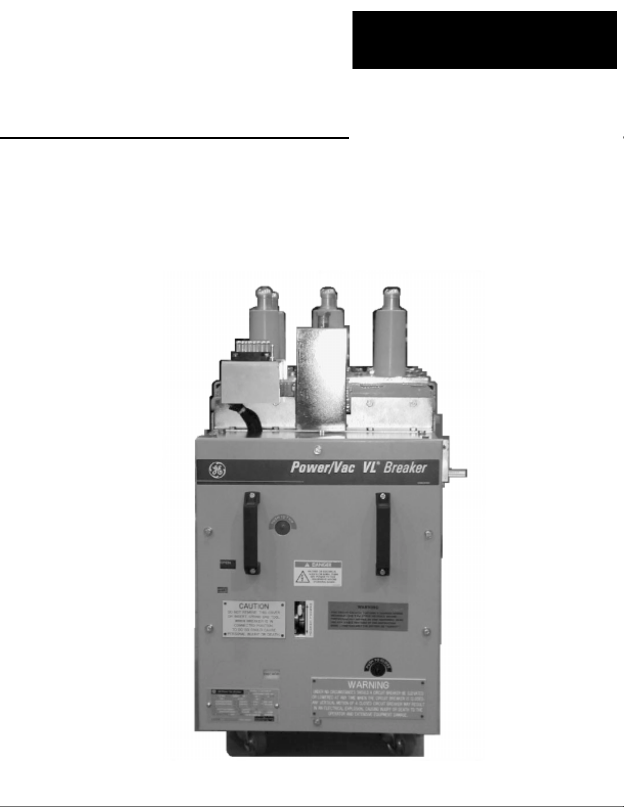
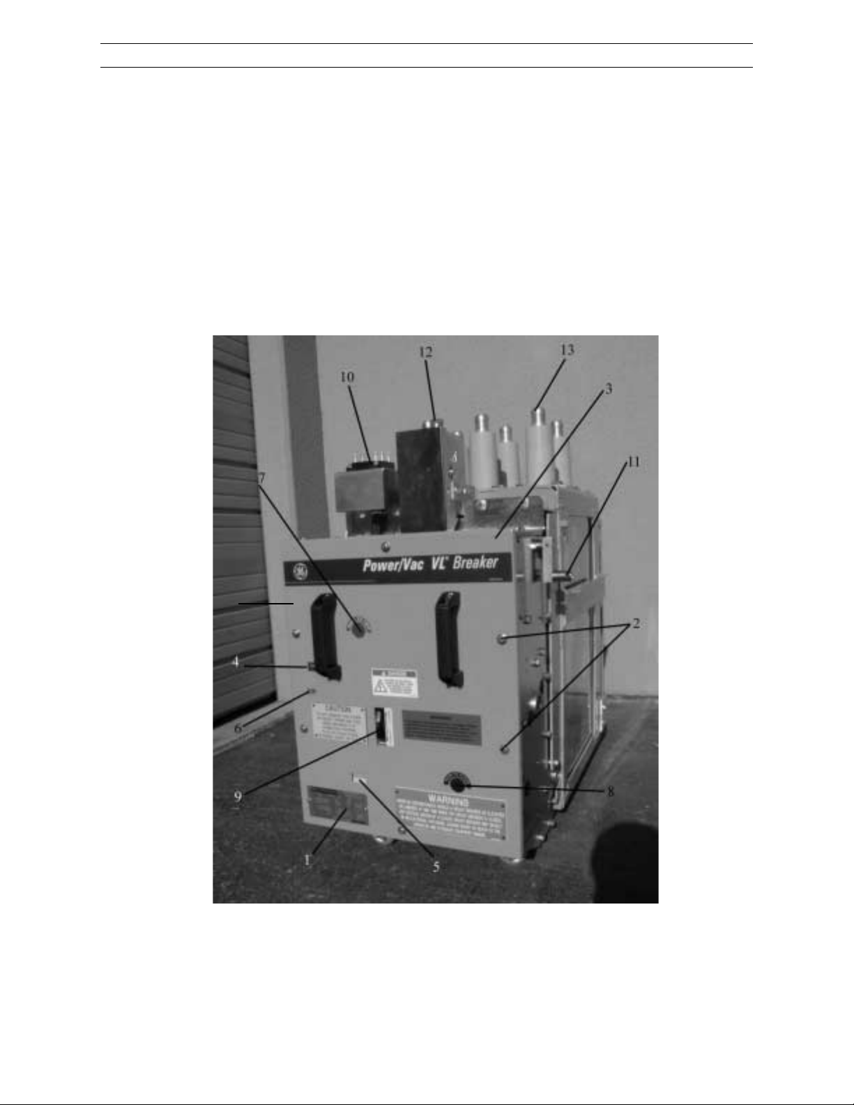
Figure 1. V iew of 5kV ‘VL ’ Br eaker with Front Cover
1 Nameplate 5 Charge/Dischar ge Indicator 9 Manual Charge Lever
2 Cover Mounting Bolts 6 Counter 10 Secondary Coupler
3 Fr ont Removable Cover 7 Manual Trip Button 11 Positive Interlock Roller
4 Open/Close Indicator 8 Manual Close Button 12 Plunger Interlock (MOC)
13 Primary Bushings (1200 Amp shown)
7
Page 8
PowerV ac® 5kV Vertical Lift
Chapter 3. Receiving, Handling & Storage
3-1. Receiving
Each breaker is carefully inspected before shipment. Immediately upon receipt of the circuit
breaker, an examination should be made for any
damage sustained in transit. If injury or rough
handling is evident, a claim should be filed immediately with the transportation company, and
the nearest GE Sales Office should be notified.
CAUTION: THE BREAKER HAS BEEN
SHIPPED IN THE CLOSED POSITION.
3-2. Handling
It is expected that care will be exercised during
the unpacking and installation of breakers so
that no damage will occur from careless or
rough handling, or from exposure to moisture
or dirt. Loose par ts associated with the breaker
are sometimes included in the same crate. Check
all parts against the packing list to be sur e that
no parts have been overlooked.
3-3. Storage
It is recommended that the breaker be put into
service immediately in its permanent location.
If this is not possible, the following precautions
must be taken to assure the proper storage of
the breaker .
The breaker should be stored in a clean location, free from corrosive gases or fumes. Particular care should be taken to pr otect the equipment from moisture and cement dust, as this
combination has a very cor r osive effect on many
parts.
Breakers should be car efully protected against
condensation, preferably by storing in a war m,
dry r oom of moderate temperature such as 40 to
100° F. High humidity may have an adverse effect on the insulating parts and should be
avoided. Circuit breakers for outdoor metalclad switchgear should be stored in the equipment only when power is available and the heaters are in operation to prevent condensation.
Rollers, latches, etc. of the operating mechanism
should be coated with GE part No.
0282A2048P009 (Mobil 28 red) grease to prevent
rusting.
If the breaker is stored for any length of time, it
should be inspected periodically to see that
corrosion has not started. Should the breaker
be stored under unfavorable atmospheric conditions, it should be serviced befor e being placed
on line.
3-4 Safety Precautions
This circuit breaker uses powerful springs for
ener gy storage. DO NOT WORK ON THE INTERRUPTERS OR THE MECHANISM UNLESS THE
CIRCUIT BREAKER IS IN THE “OPEN” POSITION AND BOTH THE CLOSING AND OPENING
SPRINGS ARE EITHER DISCHARGED OR
GAGGED AND ALL ELECTRICAL POWER IS REMOVED.
The precautions are required to prevent accidental operation. Anyone working on the circuit breaker should be familiar with the contents of this instr uction book.
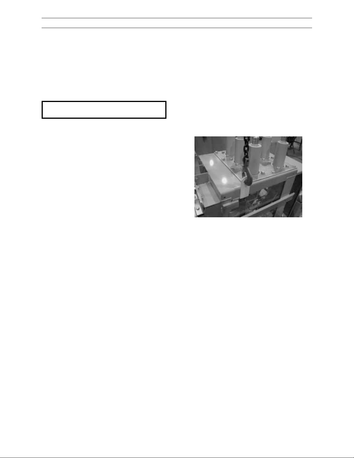
Figure 2. Hooking lifting eyes
3-5 Unpacking the Breaker
The circuit breaker has been supplied with a
box of maintenance items. After removing the
protective cardboard, locate this package and
remove two each breaker lifting eyes. After removing the cleats that attach the breaker to the
skid, hook the lifting eyes on both sides of the
breaker in line with the front edge of the primary bushing plate at the point of the lifting
arr ows (see Figur e 2). Connect a 1,000 lb. minimum rated chain fall or sling (not pr ovided) to
these lifting hooks and remove the br eaker from
the skid.
Packing List
With your breaker, you should have received:
1. Manual charging handle. (Part No.
0282A7227P001)
2. Gag tool. (Part No. 0209B8043G003)
3. Br eaker Instr uction Book DEH 40012
4. Elemenatary Wiring Diagram per breaker
summary.
5. (1)Tube of GE red grease. (Part No.
0282A2048P010)
6. (2) Breaker lifting hooks . (Part No.
0348A3356P001)
7. (6) MOC adjustment washers. (Part No.
0348A3185P001
8
Page 9
Chapter 3. Receiving, Handling & Storage
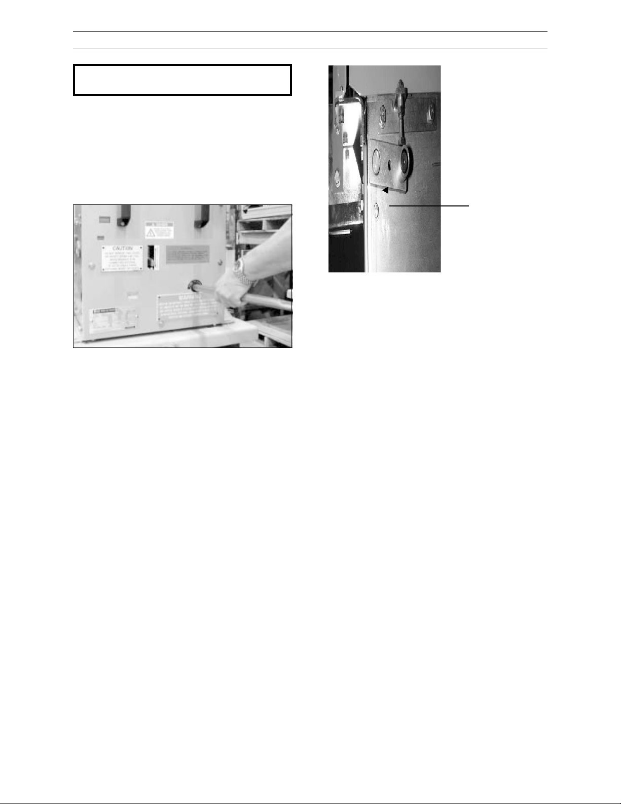
CAUTION: THE CIRCUIT BREAKER HAS
BEEN SHIPPED IN THE CLOSED POSITION.
After removing packing material, open the
breaker by pushing in firmly on the manual trip
button (Figure 2, Item 8), while keeping hands
away fr om moving parts. A safe way to do this
is to push on the trip button with the r ound side
of the maintenaince handle. Verify that the operation counter advances one count.
Figure 3. Manual T rip & Close
Closing and opening springs are now in their
dischar ged positions. Check this by first pr essing the manual close button, then the manual
trip button. The indicator flags on the front of
the breaker should show “OPEN” and
“DISCHGD”.
PowerVac® 5kV Vertical Lift
Figure 4.
Positive
Interlock
A major goal in the design of switchgear has
always been the interchangeabililty of breakers. GE Switchgear has been very successful
in achieving that goal for many years. Analysis of instr uction book adjustments, shop tolerances, and service advice letters issued in
recent years, however, has demonstrated that
tolerances in switchgear equipment installed
and presently operating can change, resulting in situations where it is impossible to meet
all adjustments. Also, when an adjustment
is brought into specification it can cause a
pr oblem with another interface or adjustment.
All mechanical and electrical checks listed in
Chapter 4 should be completed before putting
breakers in ser vice.
3-6 Safety Interlocks
Each PowerVac® VL vacuum circuit breaker is
pr ovided with the following interlocks:
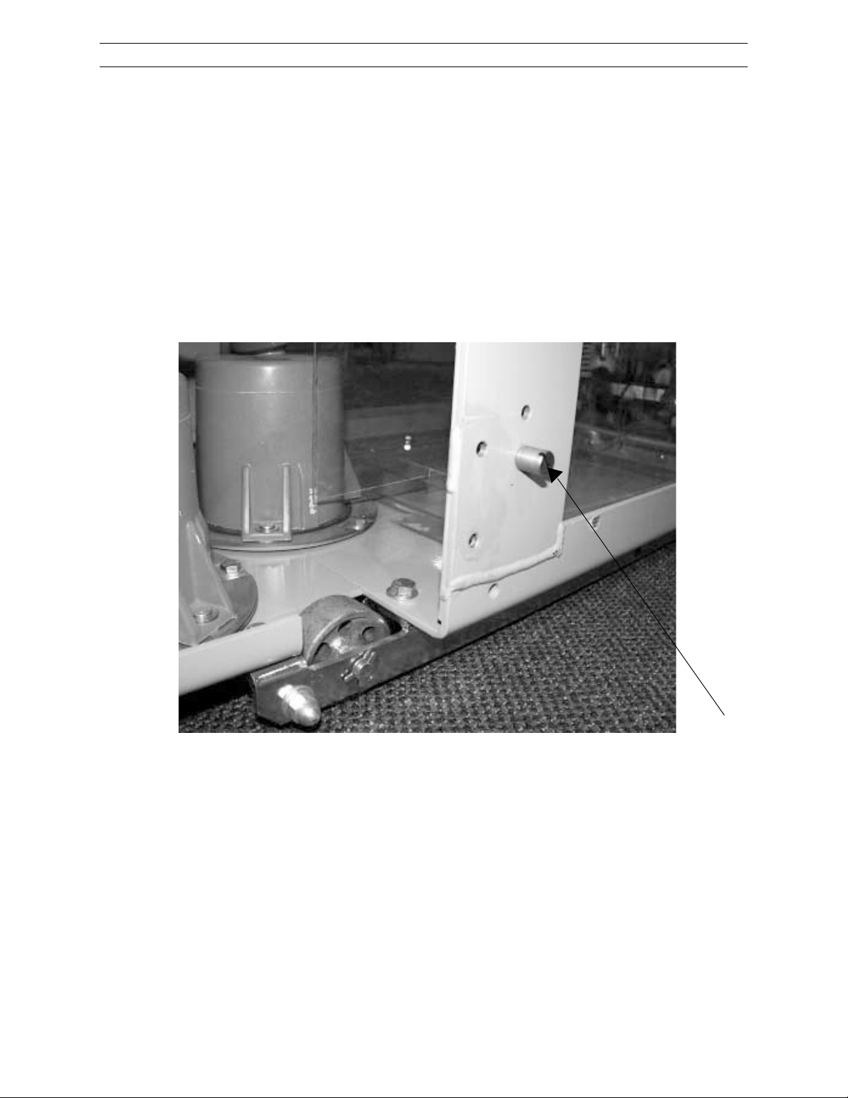
Positive Interlock System
The purpose of the positive interlock is to prevent moving the breaker to or fr om the connected
position while the main contacts are closed, and
to prevent closing the contacts unless the
breaker is in the fully connected position. These
important safety features ar e achieved by means
of the positive interlock roller on the right side
of the breaker and positive interlock cam and
stationary “flag” in the switchgear cell.
Although GE has made every effort to assure
interchangability and satisfactory inter face with
existing equipment. Older equipment and field
modifications that may have been made over
the years, may require additional procedures
before the new vacuum breaker can be installed
in the cubicle. At a minimum, all breaker-toswitchgear interfaces as explained in this section should be verified for pr oper operation prior
to energizing. The interfacing parts on all ratings of type AM breakers are functionally the
same.
The following section defines the essential dimensions relating to the interfacing
elements of the breaker and switchgear,
to assure reliable performance. Some of
these elements also affect the other important interfaces required for reliable operation of the equipment, such as:
1. Positive interlock safety feature.
2. Mechanism operation.
3. Primary disconnect penetration.
4. Secondary coupler penetration.
9
Page 10
PowerV ac® 5kV Vertical Lift
Chapter 3. Receiving, Handling & Storage
Interfer ence Bolts
This interlock permits only a breaker with a
matching continuous current rating to be inserted into a metal-clad compartment of identical rating. The rating interference bolt has been
assembled to match the current rating of the
compartment. This assembly is done by fastening a bolt on the lower left side of the breaker
truck to align with the proper cubicle interference plate. This bolt should not be removed.
Figure 5.
Figure 5. Rating Inter ference Bolt
10
Page 11

PowerVac® 5kV Vertical Lift
Chapter 4. Installation
4-1 Breaker Preparation
Prior to interfacing the breaker into the
switchgear cell, rub a small amount of
0282A2048P009 red grease, provided with the
breaker, on the silvered portion of the breaker
studs, gr ound shoe, and 16 secondary coupler
pins, to form a thin coating for contact purposes.
4-2 Equipment Test Position
In most AM breaker Metal-Clad Switchgear
units, there is a breaker “Test Position” which
allows you to functionally test the breaker without connecting to the bus. This position is lowered fully down fr om the br eaker being fully connected into the cubicle. When in the “test position”, a secondary coupler cable must be used
to connect the secondary control circuits for
electrical breaker operation.
While in the test position, the breaker interlock
is not activated. The interlock roller will not
rest in the lower “Vee” notch in the equipment
interlock cam plate allowing the operator to
close and open the breaker electrically or manually (see Figure 6).
The breaker positive interlock system should
be checked while in the test position prior to
elevating the breaker .
WARNING: FAILURE TO PROPERLY VERIFY
ALL BREAKER SWITCHGEAR INTERFACES
AND PROPER POSITIVE INTERLOCK OPERATION COULD RESULT IN A BREAKER OPERATIONAL FAILURE.
4-3 Positive Interlock
The positive interlock system prevents connecting or disconnecting the breaker in the cubicle,
when the breaker is in the closed position and
the vacuum contacts are closed.
the positive interlock r oller and lever are forced
forward by the postitive interlock cam on the
right side of the switchgear cell. The interlock
r oller and lever are held in this for ward position
during raising and lowering operations, preventing the breaker from being closed in any intermediate position between the connect and the
fully lowered position. Any attempt to charge
the breaker will cause the stor ed energy springs
to automatically dischar ge without the br eaker
contacts closing or moving. The breaker must
be fully connected (raised) and the clutch handle
must be released before the breaker can be
closed. Releasing the clutch handle allows the
interlock cam plate in the cell to move downward allowing the interlock roller and lever to
return to their normal vertical positions. The
breaker may then be closed.
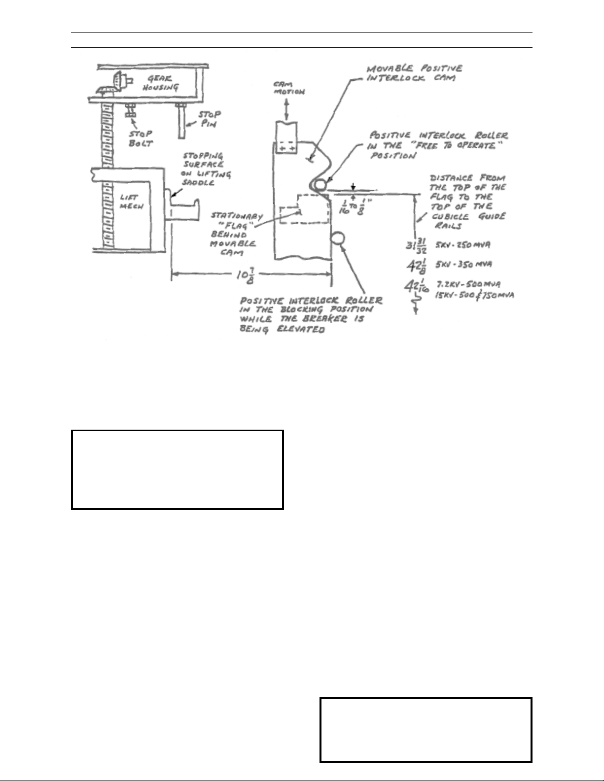
The following positive interlock adjustments are
made at the factory and verified for proper operation per Figure 6. The distance fr om the top
of the stationary flag to the top of the switchgear
guide rails is set. This maintains the surface
upon which the breaker wheels rest when the
breaker is lowered. The upper elevating motor
limit switch is then adjusted to achieve a r oller
to flag clearance of 1/16" to 1/8" as shown in
Figure 6. The limit switch de-energizes the elevating motor circuit and should be activated
when the primary disconnects and secondary
coupler reach their nominal contact penetration
position. If the timing of this sequence is off,
the cell must be adjusted back to factory specifications.
T ypical instructions for making adjustments to
the cell positive interlock cam as pr ovided with
the original equipment are outlined in Figure 6
and Figure 53.
This interlock feature is accomplished by a r oller
and lever located on the interlock shaft, on the
right side of the breaker. (Figures 1, 4 and 6)
The positive interlock lever (roller) provides a
trip-free and discharged condition when racking the breaker in the connected or disconnect
position. When the breaker is raised or lowered,
11
Page 12
PowerV ac® 5kV Vertical Lift
Chapter 4. Installation
(-0, + 1/16”)
Figure 6. Positive Interlock system
4-4 Check for Proper Interlock
and Trip-free Functions Before
Energizing the Breaker
WARNING: THE PRIMARY EQUIPMENT
SHOULD BE COMPLETELY DE-ENERGIZED
WHILE THE TESTS ARE IN PROGRESS.
DO NOT INSTALL OR REMOVE THE
BREAKER OR MAKE ADJUSTMENTS UNLESS THE BREAKER IS OPEN.
T o test the function of the positive interlock system and trip free function, the following checks
should be made:
1. Verify that red gr ease has been r ubbed on
the silvered portion of the breaker studs,
ground shoe, and 16 secondary coupler
pins, forming a thin coating for contact
purposes.
2. Before inserting the New VL vacuum
breaker into the cubicle, verify the cubicle
interlock position by measuring the distance between (Figure 6) the movable positive interlock cam to the back of the lifting
saddle of the racking mechansim. This distance should be 10 7/8” minus 0, plus
1/16”.
12
3. Lower the elevating mechanism lifting
brackets until the lifting brackets are in the
fully lowered position. The breaker should
then enter the housing freely. After first
assuring that the breaker is in the open
position, push the breaker into the unit until
it rests against the rear of the front lifting
saddle of the elevating mechanism.The
clearance between the interference block
on the breaker and the interference block
on the interlock mechanism should be fr om
.063" to .125".
4. With the breaker in the lowered position,
the positive interlock r oller engages in the
lower Vee notch, in the interlock cam plate.
The br eaker should be in the opened position and the closing springs discharged
as indicated by the flag indicators. (Figure
1, items 4 and 6) Using the manual char ging handle, char ge the breaker. Then close
the breaker and recharge. (Figure 7, Item
1). With the elevating motor switch in a
neutral position engage the clutch to verify
the operation of the positive interlock. The
springs will dischar ge and the breaker will
open.
NOTE: TABLE 3, FIGURES 6, 52, 53, AND
54 HAVE BEEN PROVIDED TO FAMILIARIZE THE OPERATOR WITH THE EQUIPMENT RACKING SYSTEM AND TROUBLESHOOTING.
Page 13
PowerVac® 5kV Vertical Lift
Chapter 4. Installation
WARNING: AGAIN, BEFORE PROCEEDING
WITH THIS CHECK, IT IS NECESSAR Y THAT
THE PRIMAR Y CIRCUITS BE DE-ENERGIZED.
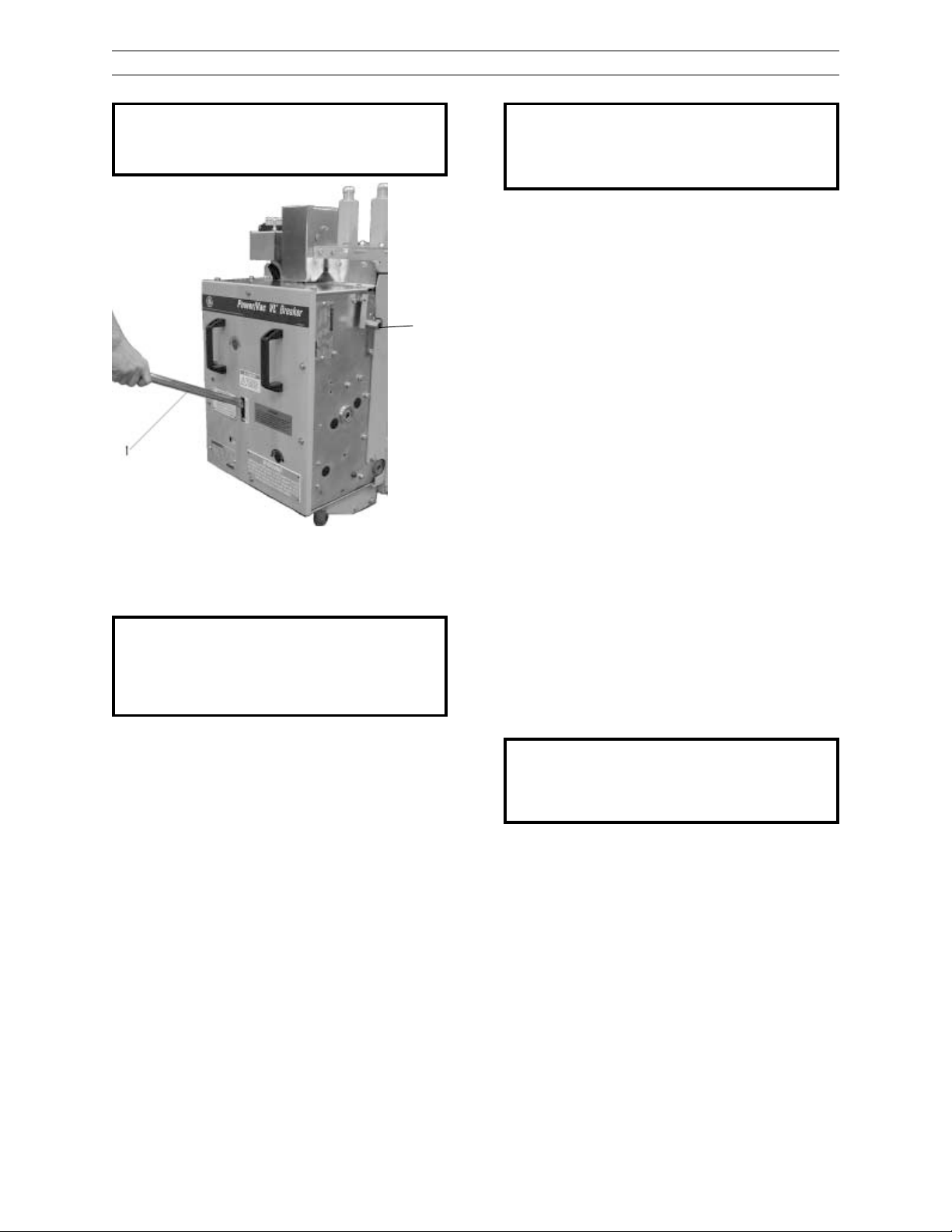
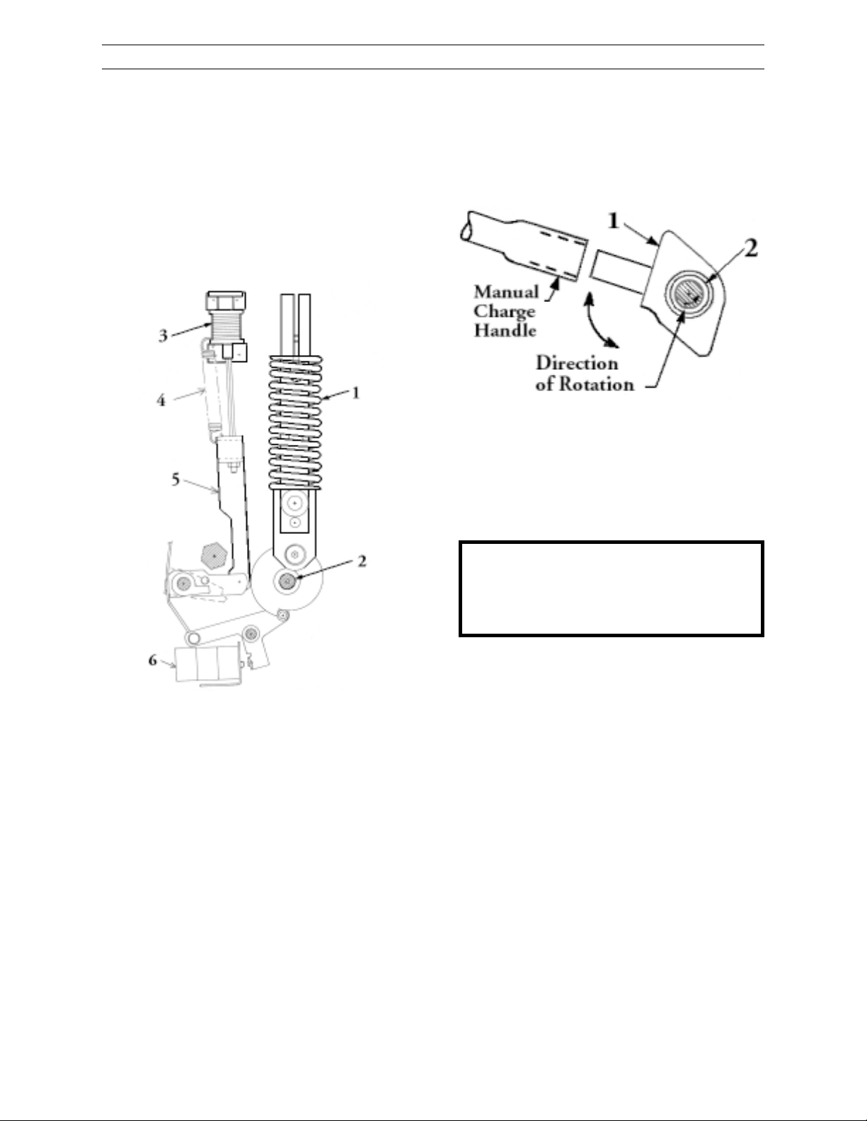
2
1 Manual char ging handle
2 Positive interlock
Figure 7. Manual char ge handle
WARNING: DO NOT A TTEMPT TO MANUALLY
CHARGE A CHARGED BREAKER. TO DO
SO COULD DAMAGE THE CHARGING
CLUTCH AND MAKE THE MANUAL CHARGING FEATURE INOPERABLE.
5. Raise the breaker to the connect position.
This can be done manually with an elevating wrench or electrically with an elevating motor pr ovided with the original equipment.
CAUTION: THE MOTOR RAISE/LOWER SE-
LECTOR SWITCH MUST NOT BE USED TO
ENERGIZE OR INTERRUPT MOTOR CIRCUIT
AT ANY TIME.
7. When the breaker is fully elevated, the clear ance between the breaker lifting rail and
the upper stop bolts should not be more
than .125" and not less than .094".
8. The positive interlock roller should be centered in the upper “VEE” and the interlock
roller should have 1/16" clearance to the
stationary plate dir ectly under it.
9. In order to lower the breaker fr om the connected position, the breaker should be
open. The closing springs will be discharged when the clutch handle is engaged.
To lower the breaker, place the elevating
control selector switch on the elevating
motor to “lower”. A clutch handle in back
of the elevating motor is then pulled forward until a limit switch engages, to lower
the breaker to the bottom of the cubicle.
10.To raise or lower the breaker, the clutch
must be held in the engaged position, otherwise a spring will return it to its disengaged position and open the electrical cir cuit to the motor.
CAUTION: THE POSITIVE INTERLOCK LE-
VER ROLLER WILL DISCHARGE THE OPENING AND CLOSING SPRINGS AS THE ELEV ATING MOTOR CLUTCH IS ENGAGED.
To elevate the breaker, first–verify the
breaker is in the open position and the closing springs are discharged. Place the elevating control selector switch on the elevating motor to “RAISE”. A clutch handle
under the elevating motor is then pulled
forward until a limit switch engages to raise
the breaker into the unit. Carefully raise the
breaker and while elevating, note that the
shutter slides open and the breaker studs
center with respect to the openings in the
stationary disconnecting devices or damage to the contacts may result.
6. Hold the clutch handle in the forward position until a limit switch on the structure
opens to stop the motor at the end of the
upward travel of the breaker. The springs
will charge when the clutch handle is released.
11. The breaker may be raised or lowered by
an emergency hand crank which can be
inserted after r emoving the motor . The motor is removed by unlatching the motor
assembly fr om its support and disconnecting the motor lead plug. After removing
the motor, inser t the manual crank and pull
the clutch forward. Rotate the crank until
the coupling engages the clutch. The
clutch handle will be held in the down
position by a latch on the crank assembly .
The breaker must be open before the crank
can be inserted and held in the clutch coupling.
13
Page 14
PowerV ac® 5kV Vertical Lift
Chapter 4. Installation
When the breaker is in the fully elevated and in
the connected position, releasing the motor
operating handle will return the positive interlock r oller into the upper Vee notch in the inter lock cam plate. The breaker positive interlock
switch will close and ener gize the motor char ging circuit allowing the closing spring to
char ge. The br eaker may now be closed.
In order to lower the breaker fr om the connected
position, the breaker should be opened. If the
breaker has not been opened, operating the
motor elevating clutch will open the contacts
and discharge the springs.
4-5 Primary Contact Penetration
After completing the Positive Interlock and trip
free functional checks, lower the break and withdraw it from the cell. Inspect the contact surfaces of both the breaker studs and the stationary disconnecting devices. The primar y disconnect devices utilize silver to silver contacts to
insure against r eduction of cur r ent car r ying capacity due to oxidation of the contact surfaces.
These contacts are of the high pressure line
contact tube and socket design, the tube being
backed up by heavy garter springs.
1. Each segment of the stationary disconnecting device should make a heavy impression in the contact lubricant on the
breaker studs as shown in Figure 9. Contact wipe should start not less than .125"
from the top of the contact ball, although
each contact need not start at the same
location.
2. The penetration of the breaker stud inside the stationary disconnecting device,
as indicated by the contact lubricant,
should be 3/4” to 7/8” as shown in Figure 9. This indicates that the breaker studs
contacted at the full pressure center of
the silver band on the stationary disconnecting device corr ectly.
3. Should the inspection of the contacts
show that the breaker is not being raised
to the proper position, readjust the upper stop bolts and limit switches to raise
or lower the breaker to the proper location (See Figure 6 and 53). Lock the stop
bolts in the new position.
4. If proper contacting cannot be attained
by the above methods, additional adjustments may be necessary.
Contact the local GE Sales Office for factory
assistance.
Figure 8. Primary Contact Insertion
14
Page 15
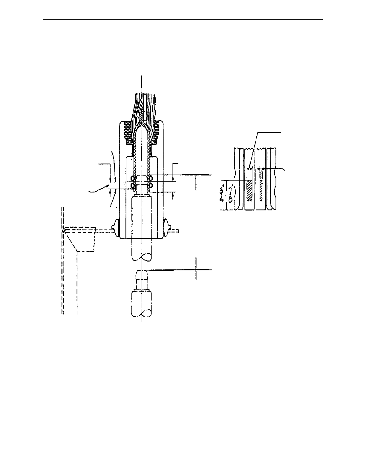
Final
Position
1/2” to 5/8”
Electrical
Wipe
Initial
Electrical
Contact
PowerVac® 5kV Vertical Lift
Chapter 4. Installation
3000A Contact
Wipe area should
be a minimum of
60% contact width
3/4” to 7/8”
1200A & 2000A
Contact Wipe
should be a line
1/16” to 1/8”
wide.
(grease wipe)
9 3/4 M 36
8 3/16 M 26
12 3/4 M 36HH
T ravel
Figure 9. Primary contact penetration and wipe
15
Page 16
PowerV ac® 5kV Vertical Lift
Chapter 4. Installation
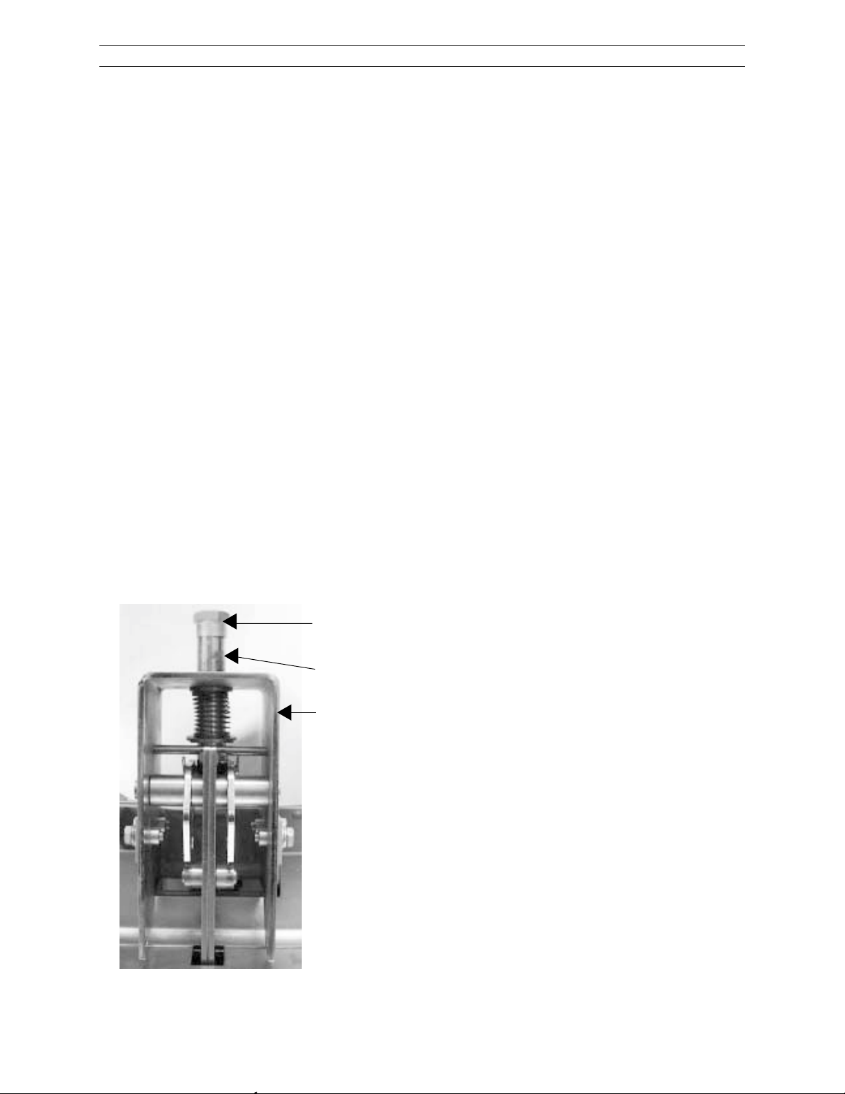
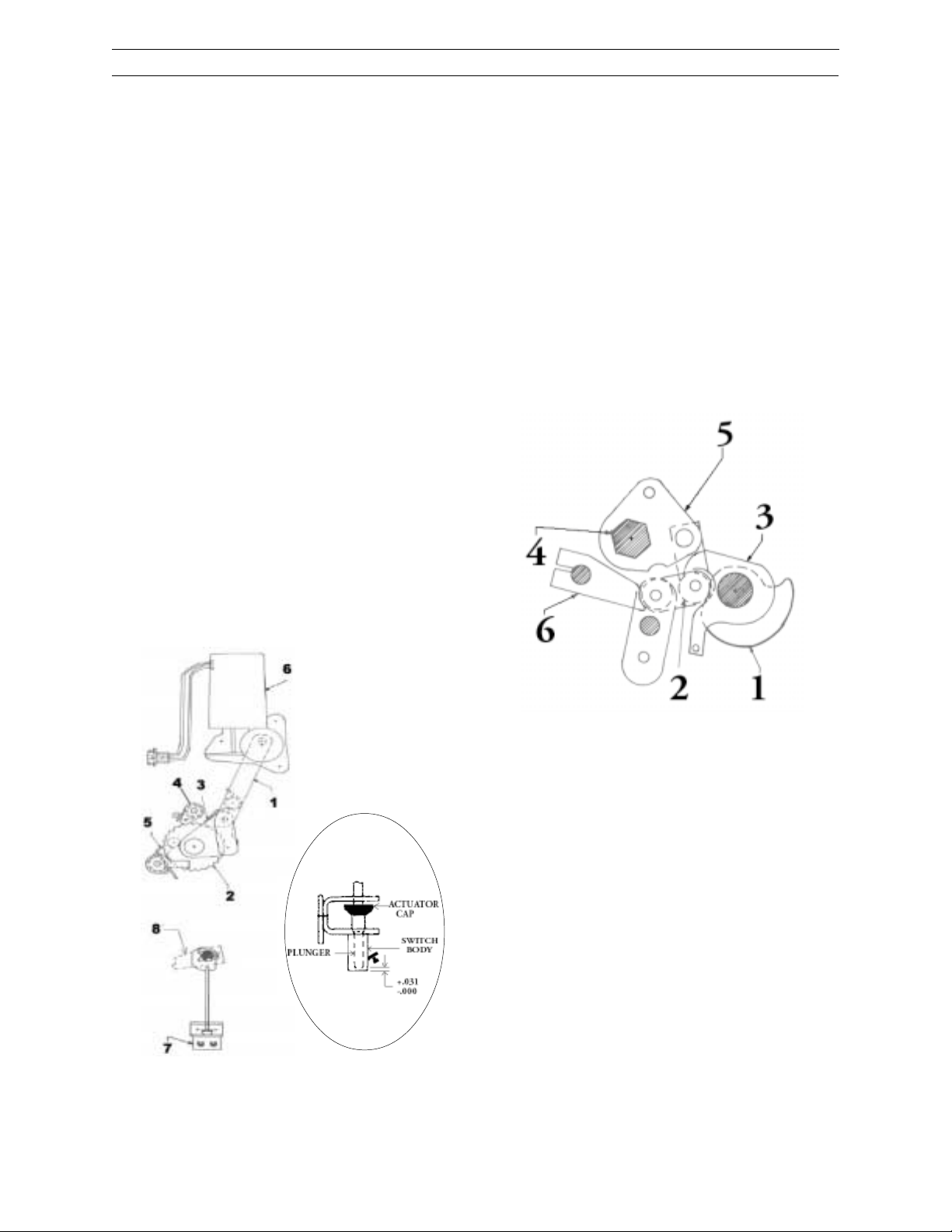
4-6 Stationary Auxiliary Switch
(MOC)
The Stationary Auxiliar y Switch is a Mechanism
Operated Contact (MOC) which is an optional
switch mounted in the switchgear cell. When
the breaker has been elevated to the fully connected position, the MOC switch will be actuated whenever the breaker is closed. The MOC
switch is actuated by the plunger mounted on
the top of the breaker mechanism. (Figure 10
Item 1). The MOC switch has a number of “a”
contacts (closed when the breaker is closed and
open when the breaker is open) and “b” contacts (open when the breaker is closed and
closed when the breaker is open).
The following paragraph defines the essential
dimensions relating to the interfacing elements
of the beaker and switchgear, to assure r eliable
performance.
The following elements are important factors
which commonly affect the operation of the stationary auxiliar y switch.
1. Adjustment
washer
2. Operating
switch rod
1. Plunger travel on the br eaker .
2. The gap between the top of the plunger
on the breaker and the bottom of the r od
on the stationary auxiliar y switch mechanism.
3. V ariations between breakers in the distance
from the underside of the lift rail and the
top of the plunger .
4. Variations in the r otation requir ements to
“make” and “break” the stationar y auxiliary switch contacts.
5. Condition of the plunger interlock components on the breaker .
6. Elevating mechanism limit switch consistency.
7. Break elevating mechanism positive stops.
8. Seismic events.
Some of these elements also affect the other
important inter faces requir ed for r eliable operation of the equipment, such as:
1. Primar y disconnect penetration.
2. Secondar y coupler penetration.
3. The positive interlock mechanism.
A major goal in the design of switchgear has
always been the interchangeability of breakers.
GE Switchgear has been very successful in
achieving that goal for many years. Analysis of
instr uction book adjustments, shop tolerances,
and service advice letters issued in r ecent years,
however , have demonstrated that tolerances in
switchgear equipment installed and presently
operating can result in situations where it is
impossible to meet all adjustments or that an
adjustment is br ought into specification and it
causes a pr oblem with another interface.
Figure 10. MOC switch
3. Plunger
interlock
4-7 Stops
The stop pins and stop bolts on the elevating
mechanism are emergency mechanical stops
which would come into use only if the upper
elevating motor switch is completely out of adjustment or has failed. Elevating against these
stops may be quite audible and the operator
should release the clutch handle immediately,
de-ener gizing the elevating motor circuit or the
elevating motor circuit pr otective fuse will open
to protect the motor. The stop bolts should be
set to 3/32" to 1/8" clearance and only changed
or reset after all other elevating adjustments are
made and verified. Figure 6 and 53.
4-8 Ground
A visual check should be made to observe the
ground connection. The ground shoe on the
moveable breaker is designed to have a nominal engagement of 1-1/2" +1/4" vertically with
the steel and copper spring loaded disconnects
of the gr ound device in the switchgear.
16
Page 17
PowerVac® 5kV Vertical Lift
Chapter 4. Installation
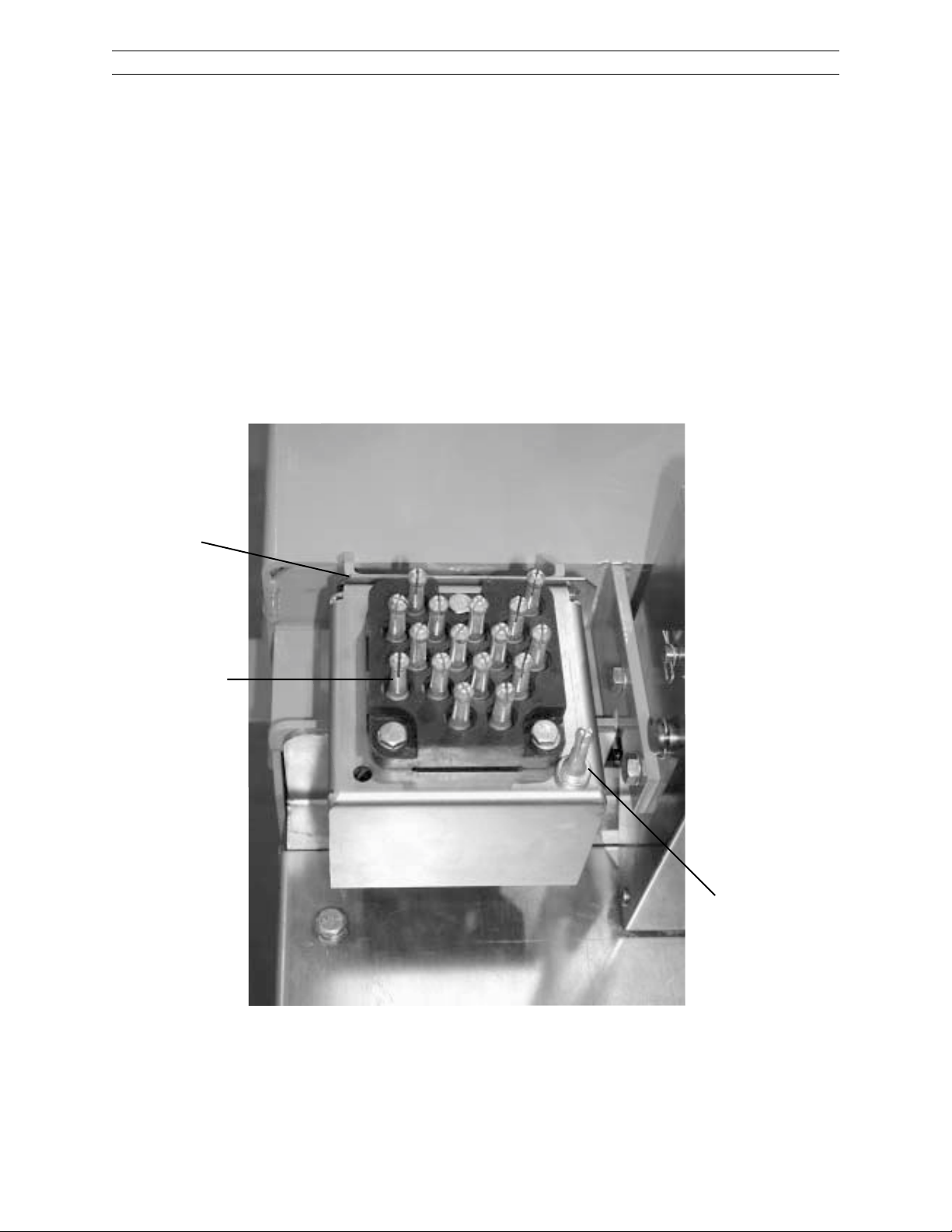
4-9 Secondary Coupler
On the top left front of the breaker, there is a
plastic block which holds the male secondary
coupler pins. This block should make contact
with, and slightly raise a spring loaded plastic
block which holds female secondary coupler
sockets on the switchgear . The contact depression should be 1/8". It is not always possible
to have the plastic blocks in contact over their
entire flat surface. Often, the rear of the blocks
are engaged while a gap exists along the front
edge. This is an acceptable condition. The contacting block surfaces should touch and the female block edge move upward between1/32" to
1/8". See Figure 11.
1
4-10 Position Switch (TOC)
The position switch is an optional device
mounted in the rear left side of the switchgear
cubicle. The switch contacts operate when the
lifting mechanism is in either the fully raised or
fully lowered position. Switch operation should
be checked with the breaker withdrawn manually and the equipment de-energized, and again
electrically, with the breaker in the cubicle.
2
3
1 Secondary disconnect block shims
2 16 Secondary disconnect pins
3 Ground pin for use with a test cabinet
Figure 11. Secondary disconnect coupler
17
Page 18
5-1 Description
PowerV ac® 5kV Vertical Lift
Chapter 5. Operation
The PowerV ac® 5kV VL vacuum circuit br eaker
uses a sealed vacuum power interrupter to establish and interrupt a primary circuit. Primary
connections to the associated metal-clad
switchgear are made by pole assemblies, electrically and mechanically connected to the
vacuum interr upters. The operating mechanism
provides vertical motion at each pole location
in order to move the lower contact of the
vacuum inter r upters fr om an open position to a
spring-loaded closed position and then back to
the open position on command.
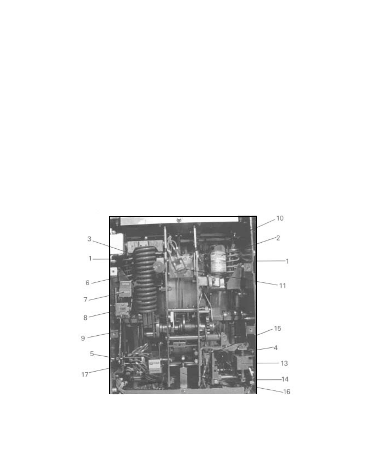
The ML-19 mechanism (Figure 12) is a storedener gy type mechanism and uses a gear motor
to char ge a closing spring. During a closing operation, the ener gy stored in the closing spring
is used to close the vacuum interr upter contacts,
charge the wipe springs which load the contacts, char ge the opening springs, and overcome
bearing and other frictional forces.
The energy then stored in the wipe and opening springs will open the contacts during an
opening operation.
Closing and opening operations are contr olled
electrically by the control switch on the metalclad door or remote relaying.
Mechanical contr ol for maintenance or emergencies is provided by manual close and trip buttons on the circuit br eaker.
Also, the closing spring may be manually
char ged (Figure 7) for de-energized checks and
maintenance.
Figure 12. Fr ont View of ML-19 Mechanism with Fr ont Cover Removed
1 Opening Spring
2 Char ging Motor
3 Close Spring
4 Manual Close Button
5 Char ge/Dischar ge Indicator
6 Manual T rip Button
7 Open/Close Indicator
8 Counter
9 Manual Charge Lever
10 Positive Interlock Switch
11 Close Relay
12 Cam shaft
13 Close coil
18
14 Close coil adjustment collar
15 Close latch check switch
16 Opening dashpot
17 Auzilary switch
18 MOC Plunger linkage
19 Positive interlock bar
Page 19
PowerV ac® 5kV Vertical Lift
Chapter 5. Operation
5-2 Close Spring Charging
Figure 13 shows a left side view of the closing
spring. The closing spring is char ged and ready
to close. The closing spring charging system
consists of a closing spring mounted on the
left side of the breaker and the electrical char ging system mounted on the right side of the
breaker. Both components are fastened to the
cam shaft (Figure 13, Item 2).
A manual char ging system is provided to manually char ge the br eaker, or while under maintenance so that the mechanism can be slow
closed and the closing spring can be charged.
(Figure 14, Item 1)
Figure 14. Manual Char ging system
right side view
1 Manual char ging crank
2 One way clutch
Figure 13. Charging & Trip system left side view
1 Closing spring 4 Trip r eturn spring
2 Cam shaft 5 Trip linkage
3 T rip Solenoid 6 52 Chg & SM/LS switch
WARNING: DO NOT ATTEMPT TO MANUALLY CHARGE A CHARGED BREAKER. TO
DO SO COULD DAMAGE THE CHARGING
CLUTCH AND MAKE THE MANUAL CHARGING FEATURE INOPERABLE.
The manual char ging system (Figure 14) works
directly on the cam shaft where a one-way
clutch (Figure 14, Item 2), driven by a manual
handle, pr ovides rotation of the ratchet wheel.
Manual pumping of the handle advances the
ratchet wheel and the holding pawl prevents
counter -r otation while the handle is retur ning
for another str oke. Approximately eight complete str okes of the manual handle are requir ed
for one complete spring-char ging operation.
When the spring charge indicator (Figure 1,
Item 5) shows “CHARGED”, MANUAL CHARGING MUST BE DISCONTINUED TO AVOID
MECHANISM DAMAGE.
19
Page 20
PowerV ac® 5kV Vertical Lift
Chapter 5. Operation
Spring char ging is accomplished electrically by
a rotating eccentric on the output shaft of a
gear motor (Figure 15, Item 6) which in turn
drives pivoted charging arms (Figure 15, Item
1). The charging arms oscillate about the
centerline of a ratchet wheel (Figure 15, Item 2).
A driving pawl (Figure 15, item 3), mounted
within the charging arms, oscillates with the
char ging arms. Star ting fr om its rear-most position, the charging arms rotate forward, while
spring forces engage the driving pawl with a
tooth on the ratchet wheel. The ratchet wheel is
advanced by the r otating char ging arms and pawl
assembly . Advancement of one tooth spacing
is provided for each oscillation of the system.
The ratchet motion is restricted to one direction by a spring-loaded holding pawl (Figure
15, Item 4) that prevents the ratchet wheel fr om
going backwards as the charging arm oscillates back to pick up the next tooth. Thirteen
complete cycles of the char ging arms ar e needed
for a full char ge of the closing spring. The efficient, compact gear motor accomplishes this
action in about two seconds. When the charging cycle is complete, the ratchet wheel is positioned so that a missing tooth is adjacent to the
driving pawl and any motor overspin will not
drive the ratchet wheel, thus preventing damage to the system.
The closing coil cannot be electrically energized
unless the closing spring is completely char ged.
This action is prevented by the 52/CHG switch
in the closing circuit. (Figure 13, Item 6)
5-3 Trip Free Operation
The linkage is mechanically trip-free in any location on the closing stroke. Electrically energizing the trip coil while closing will, after the
auxiliary switch contacts change position, rotate the trip latch and permit the cir cuit breaker
to open fully . The linkage will r eset as in a normal open operation and the closing spring will
rechar ge as described under “CLOSE SPRING
CHARGING”.
View rotated
90 degrees
1 Charging arms 5 Close latch
2 Ratchet wheel 6 Charging motor
3 Driving pawl 7 52 LCS switch
4 Holding pawl 8 T rip latch
Figure 15. Electrical Char ging system
right side view
1 Closing cam 4 Primary cross shaft
2 Closing roller 5 Primary drive crank
3 Close prop latch 6 Trip latch
Figure 16. Closing linkage left side view
5-4 Closing Operation
By either energizing the close solenoid or depressing the manual close button(Figure 1 , Item
8) the close latch (Figure 15, Item 5) is r otated,
releasing the closing spring (Figure 13, Item 1).
This action releases the energy in the closing
spring and transmits it to the closing cam (Figure 16, Item 1) and closing r oller (Figure 16, Item
2) causing the linkage to rise until the close prop
(Figure 16, Item 3) can slip under the close r oller
(Figure 16, Item 2) and hold the linkage in place.
As the linkage moves, the primary drive crank
(Figure 16, Item 5) r otates the primary cr oss shaft
(Figures 16 & 17, Item 4) which in turn rotates
the outer phase bell cranks. (Figure 17, item 2)
20
Page 21
PowerVac® 5kV Vertical Lift
Chapter 5. Operation
The rotation of the primary cross shaft rotates
two outer phase bell cranks which compress
the outer opening springs (Figure 17, Item 1).
The primary cr oss shaft also rotates two sets of
inner drive cranks that in turn rotate two outer
sets of secondary drive cranks, (Figur e 18, Item
2) As the outer secondary drive cranks rotate
about the secondary cr oss shaft, the center drive
cranks are rotated. The rotation of the secondary drive cranks close the vacuum inter r upters,
and compresses the wipe springs on all three
phases . (Figure 18, Item 1) The inter r upters are
driven closed through insulated operating rods.
(Figure 18, Item 4). This inter rupters are driven
closed through insulated operating rods (Figure 18, Item 4)
The rotation of the primary cross shaft (Figure
17, Item 4) also changes the auxiliary switch
position. (Figure 17, Item 3) The position flag
on the front panel will then indicate “CLOSED”.
After the breaker is closed, the char ging motor
is again energized and the closing spring is
charged as described under “CLOSE SPRING
CHARGING”. Spring char ging is possible when
the breaker is in the closed position because
the linkage is held in place by the prop.
5-5 Opening Operation
By either ener gizing the trip solenoid (Figure 13
Item 3) or depressing the manual trip button
(Figure 1, Item 7), the trip latch (Figure 16, Item
6) is r otated, permitting the linkage to collapse.
The vacuum inter rupter contacts will then open
under the force of the wipe springs (Figure 18,
item 1) and opening springs (Figure 17, item 1).
At the end of the opening stroke, the center
phase secondary drive cranks hit the dashpot
limiting overtravel and r ebound.
Rotation of the Primary cross shaft from the
closed to the open position operates the auxiliary switch (Figur e 17, Item 3) opening the trip
coil circuit. When the closing spring has been
recharged,( Figure 13, Item 1) the linkage is reset allowing the trip latch (Figure 16, Item 6) to
rest in place on the trip r oller, ready for another
closing operation. If the closing spring has not
been recharged, the trip latch will be held out
of position. A latch-checking switch, 52 LCS
(Figure 15,Item 7) will not close unless the latch
is in its normal position. The contacts of the
latch-checking switch are par t of the closing cir cuit and will not allow for an electrical close
until the latch is reset.
1 Opening Spring 3 Auxilliar y switch
2 Outer bell cranks 4 Primar y cross shaft
Figure 17. Opening spring & auxialliary
switch left side view
1 Wipe spring 4 Insulated operating rod
2 Secondary drive crank 5 Wipe indicator
3 Secondary cross shaft
Figure 18. Wipe Spring assembly-
left side view
21
Page 22

PowerV ac® 5kV Vertical Lift
Chapter 6. Control Circuit
6-1 Controls
A Standard inter nal wire har ness for a PowerVac
VL circuit breaker ML-19 mechanism is shown
in Figure 19. The wiring from the breaker
internals to the secondary disconnect varies
with each breaker. Two typical breaker wiring
diagrams have been pr ovided (Figure 20 and Figure 21). Always follow the wiring diagram supplied with the actual circuit breaker for trouble
shooting purposes.
The close spring-charging motor circuit is established through the CL/MS (Close Latch Monitor Switch) Switch, if the close latch is reset
and the SM/LS (Spring Motor Limit Switch)
Switch is closed, the motor will char ge the closing spring. When the closing spring is char ged,
the SM/LS interrupts the circuit.
®
The close coil circuit is established thr ough two
normally closed 52Y r elay contacts, and the Latch
Checking Switch (LCS). If the trip latch is reset,
an auxiliary switch contact 52b is also in series
with the close coil and closes when the breaker
is open and opens when the breaker is closed.
During a close operation, the cam r otation closes
the SM/LS contact allowing the 52Y relay to be
ener gized. The 52Y relay opens its contacts, in
the close coil circuit and seals itself in thr ough
one of its own contacts. This seal-in action prevents re-closing on a sustained close command.
The close signal must be removed to drop out
the 52Y relay and reestablish the closing circuit. This pr ovides the anti-pump feature.
Circuit breaker-mounted auxiliary switch contacts that are not used in the control circuit are
br ought out for contr ol and indication functions.
The metal-clad equipment may provide a br eaker operated stationary auxiliary switch for additional contacts.
Figure 19. T ypical ML-19 mechanism internal wiring connections.
22
Page 23

PowerVac® 5kV Vertical Lift
Chapter 6. Control Circuit
Figures 20 and 21 show typical wiring diagrams
for PowerV ac® VL breakers.
Replacement breakers for old units with solenoid mechanisms (AM breakers with MS type
mechanisms) are typically wired per the drawing in Figure 20.
Replacement breakers for old units with stored
ener gy mechanisms (AM breakers with ML type
mechanisms) are typically wired per the drawing in Figure 21.
The wiring on your breakers may be different.
Consult your nameplate for the corr ect drawing
number and call your local GE office when additional copies of this drawing are required.
Figure 20. T ypical breaker wiring diagram
(Replacement for breakers with MS mechanisms)
23
Page 24

PowerV ac® 5kV Vertical Lift
Chapter 6. Control Circuit
Figure 21. T ypical breaker wiring diagram
(Replacement for breakers with ML mechanisms)
24
Page 25

PowerVac® 5kV Vertical Lift
Chapter 7. Mechanical Checking and Slow Closing
7-1 Visual Inspection
Visually inspect the circuit breaker for any signs
of damage or loose hardware.
7-2 Closing Spring Charging
Manually char ge the breaker closing spring using the char ging handle provided. (Figur e 7, Item
1) The closing spring is charged by a
ratcheting mechanism that advances one
ratchet tooth at a time. Approximately eight
complete strokes ar e requir ed. When the spring
is fully charged, the spring load is held by the
closing latch. The spring indicator (Figure 1,
Item 5) changes from “DISCHGD” to
“CHARGED”, and a positive snap is heard as
the spring travels over center.
CAUTION: AFTER THE SPRING IS COM-
PLETELY CHARGED, AS INDICATED ABOVE,
FURTHER FORCING THE CHARGING
HANDLE MAY CAUSE DAMAGE TO THE
CLOSING LATCH AND ITS ASSOCIATED
PARTS.
7-3 Closing Spring Gag
Remove the mechanism front and top covers
and insert the tip of the closing spring gag tool
(Figure 22, Item 2) between the end of the spring
and the spring guide, engaging the détentes
(Figure 22, Item 3) on the gag tool into the slots
in the closing spring guide. (Figure 22, Item 4)
Reference also Figure 48.
With the gag tool in position depress the
manual close button. This action will partially
discharge the closing spring and also partially
close the vacuum interr upter contacts.
7-4 Slow Closing
To manually slow close the breaker contacts,
remove the top plate of mechanism. Install the
closing spring gag, as described above. Put the
manual charge handle on the manual charge
lever and move the handle up and down. The
breaker will be fully closed when the spring
char ge indicator shows “CHARGED”
CAUTION: WITH THE GAG TOOL INSTALLED,
THE BREAKER CLOSED, AND OPENING
SPRINGS CHARGED, THE BREAKER CAN BE
TRIPPED AT FULL SPEED.
1 2
3
4
5
6
1 Tie bar 4 Closing spring guide
2 Gag tool 5 Spring pin
3 Gag tool détentes 6 Closing spring
Figure 22. Closing spring with gag tool
inserted
CAUTION: DO NOT REMOVE TIE BAR (FIGURE 18, ITEM 1) UNLESS SPRING HAS BEEN
REMOVED FROM THE BREAKER.
CAUTION: DO NOT ENERGIZE THE SEC-
ONDARY CONTROL CIRCUIT AT THIS TIME.
USE OF THE GAG TOOL SHOULD ONLY BE
ATTEMPTED WHEN THE BREAKER IS OUT
7-5 Gag Tool Removal
T o r emove the gag tool, the closing spring must
be fully char ged. If the spring charge indicator
does not show “CHARGED” in the window,
manually char ge the spring until it does. Lift up
and push down and away on the gag tool to
clear the détentes on the gag tool from the slots
in the closing spring guide. For safety, first close
the breaker by depressing the manual “CLOSE”
button and then depress the manual “TRIP”
button. All stored ener gy is now r emoved fr om
the breaker .
25
Page 26

PowerV ac® 5kV Vertical Lift
Chapter 8. Dimensional Checks
8-1 Primary Contact Erosion
The vacuum inter r upter is a sealed unit and the
contacts are not visible. The contacts are designed for 0.125” total wear. When 0.125” of
wear has occured , the vacuum inter r upter must
be replaced. V acuum inter r upters are typically
good for 25 full rated interruptions before the
0.125” wear has been reached. Vaccum interrupters are also good for in excess of 10,000
no- load operations and 5,000 load operations.
The mechanical seal system will develop a leak
in the bellows before the contacts will reach
0.125” wear . See Chapter 9 for vacuum integrity
test..
6
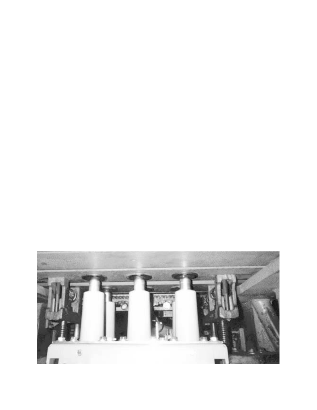
Each inter r upter has been premeaseur ed at the
factory for the primar y contact gap and this measurement has been recorded on the ceramic
bottle. This measurement varies fr om phase to
phase and from breaker to breaker but is appr oximately 4 inches. The actual measurement
“A” is the distance from the bottom of the insulated operating r od to the bottom of the lower
stainless steel inter r uptor suppor t as shown in
Figure 24. To determine contact wear r epeat
this measurement on each phase and subtract
the measurement fr om the factory r ecorded measurement. If the difference is 0.125“ or greater
then the vacuum interr uptor should be replaced.
See Chapter 12.
8
1
2
3
5
4
1 Operating Rod Insulator
2 Wipe Indicator
3 Wipe Gap
4 Wipe Spring
5 Lock Nut and Lock Washer
6 Coupling Clamps and Screws
7 Hexagon Pr ojection
8 Interrupter Movable Contact Rod
Figure 23. Contact Er osion Indicator
1
7
2
3
4
5
6
1. Lower Interrupter support 4. Insulated
2. Moving contact rod operating rod
3. Coupling clamp 5. Masking Tape
6. Reference block
Figure 24. Primary contact er osion
measurment - rear view .
8-2 Spring Wipe Indicator
The wipe springs are preloaded to a length of
2.25 inches When the breaker is closed, the secondary drive cranks will continue to move upwards after the primary contacts in the vacuum
inter ruptor have been closed. This over travel
is taken up by compressing the wipe springs.
The over travel distance is pre-adjusted at the
factory to be 0.125” minimum. The spring wipe
can be verified by viewing the wipe indicator.
(Figure 23, Item 2) The wipe indicator has four
red lines that make up a total distance of 0.125”.
The wipe indicator was preset at the factor y so
that when the breaker is char ged and closed all
four red lines should be visible above the wipe
plate.
26
Page 27

PowerVac® 5kV Vertical Lift
Chapter 8. Dimensional Checks
With the breaker closed and
char ged and the closing spring
gagged for safety (Chapter 7-3),
verify that each phase has sufficient spring wipe. If more
then two red lines are showing
the breaker wipe is sufficient.
The minimum wipe, 0.050”, has
been reached when the white
space between the second and
third line is no longer visible
above the wipe plate. Adjustment is not required until wipe
is 0.050 inch or less.
If adjustment is required see
WIPE ADJUSTMENT in MECHANICAL ADJUSTMENTS
Chapter 11-2.
1 Operating rod insulator
2 Operating rod nut
3 Wipe indicator
Figure 25. Wipe indicator check and wipe measur ement -
rear view .
4 Wipe Indicator adjustment nut
5 Actual Wipe measurement
1
2
3
4
5
8-3 Contact Gap
The method of measuring the contact gap is as
follows: First with the breaker in the open position, the closing springs char ged, and the closing spring gag tool installed for safety (Chapter
7-3), apply a piece of masking tape to the surface of the operating r od insulator as shown in
Figure 24. Using a reference block, make a mark
on the tape near the top on all three poles. The
reference block should be 6 23/32” long, if the
breaker mechanism has been r emoved from the
breaker tr uck, or X” if verifying the gap with the
element installed in the truck. It is also advisable to put a reference mark on the tape to identify to which pole the tape is applied.
Remove the closing spring gag tool and close
the breaker . Using the same pr ocedure as above,
re-mark the tape. This new mark will be near
the bottom of the tape. T rip the breaker, remove
the tapes and re-apply them to a flat surface.
Measure the distance between the two lines. A
caliper will give an accurate reading of the contact gap.
and 0.600” for all three phases.
A properly adjusted br eaker will generally have
less gap and wipe on the center pole than on
the outside poles. Due to the fact that the outer
phases are dir ectly driven by the secondary drive
cranks by the primary cross shaft and the center phase is driven by the secondary drive cranks
by the secondary cross shaft, the center phase
tends to lag the outer phase during opening and
closing. See Chapter 5-4 and 5-5 for a thor ough
description on opening and closing. It is important that the three phases do not open or
close more than two milliseconds apart from
each other . In general the center phase will need
a gap of 0.020” less than the outer phases to
prevent any phase stagger. If the center phase
measures 0.550” nominally then the outer phase
should be appr oximately 0.570”.
Dimension B: The gaps must be between 0.480”
27
Page 28

PowerV ac® 5kV Vertical Lift
Chapter 9. Electrical Checks
9-1 Electrical Operation
Electrical checking consists of electrical breaker
operation primary and seconar y wiring high-potential testing (if required), primary circuit
reistance (if requir ed), PowerV ac interr upter highpotential testing, and insulation resistance to
ground.
T o check the electrical operation with the br eaker
removed from the cubicle, attach a secondary
test coupler to the circuit breaker connector and
the other end to the secondary coupler mounted
in the cubicle. Check the contr ol voltage on the
nameplate and close and open the breaker several times.
CAUTION: REPEATED OPERATIONS AT A RATE
EXCEEDING TWO PER MINUTE MAY CAUSE
CHARGING MOTOR OVERHEATING AND FAILURE.
Leave the circuit breaker in an open and spring
dischar ged condition after checks are complete
and before inserting the circuit breaker into a
metal-clad unit. Reinstall the front cover if it
has been removed.
9-2 High-Potential Test
If hi-potential tests to check the integrity of the
insulation are required, the AC hi-potential test
described below is strongly r ecommended. DC
high-potential testing is not recommended. The
following pr ocedure must be adher ed to.
If the test should experience a failure, STOP,
turn off the test set and discharge the breaker
circuit.
1. Check the test setup and leads for connection er rors.
2. Wipe down the breaker to remove any
moisture, dust and contamination.
3. Retest the breaker at the pr oper test voltage.
Secondary Circuit
Prior to hi-potting the breaker secondar y circuit,
disconnect the motor leads and thread a wire
connecting all secondary coupler pins. Connect the hi-pot machine fr om this wire to gr ound.
Increase the voltage to 1125 volts (rms) 60 Hz
and maintain for 60 seconds. Reduce the voltage to zero and r emove the hi-pot machine connections from the cir cuit. Remove the wir e connecting the secondary coupler pins and r econnect the motor leads.
9-3 Primary Circuit Resistance
A resistance check of the primary circuit may
be made with the breaker closed. Use a low
resistance measuring instrument which measures micro-ohms. The 100 ampere reading
should be less than 40 micr o-ohms when connected.
CAUTION: IF DC HIGH-POTENTIAL TESTING IS
REQUIRED, THE DC HIGH POTENTIAL MACHINE
MUST NOT PRODUCE PEAK VOLT AGES EXCEEDING 50 KV.
NOTE: ALWAYS RECHECK WITH AN AC TEST
SET, IF INITIAL RESULTS ARE QUESTIONABLE.
Primary Circuit
The breaker should be AC hi-potted in the closed
breaker mode to verify the insulation system.
An AC hi-pot machine capable of producing the
test voltages shown below may be used to hipot the breaker phase to phase and phase to
ground.
BREAKER VOLTAGE TEST VOLTAGE
4.16 kV 14 kV
CAUTION: DISCONNECT THE SURGE SUPPRES-
SORS BEFORE HI-POTTING THE CIRCUIT BREAKER.
The machine should be connected with its output potential at zero and the voltage incr eased
at 500 vps to the test voltage and that voltage
maintained for 60 seconds. The voltage should
then be retur ned to zer o and the hi-pot machine
removed from the circuit. Do not exceed the
test voltage indicated for the applicable breaker
voltage rating.
9-4
Vacuum Interrupter Integrity T est
NOTE: USE OF A DC HI-POT IS NOT RECOMMENDED,
BUT CAN BE USED FOR QUICK FIELD CHECKS ONLY.
ALW AYS RECHECK WITH AN AC TESTER IF INITIAL RESULTS ARE QUESTIONABLE. PRIOR TO PERFORMING
ANY VACUUM INTERRUPTER INTEGRITY TEST, THE
OUTSIDE (EXTERNAL SURFACE) OF THE V ACUUM INTERRUPTERS SHOULD BE WIPED CLEAN OF ANY
CONTANMINATES WITH A NON-LINTING CLOTH OR
INDUSTRIAL TYPE WIPER. THIS IS
TIRE EXTERNAL SURFACE IS TO BE COMPLETELY FREE
OF ALL DIRT, DEBRIS, DUST , OIL, ETC.
CAUTION: X-RADIATION WILL BE PRODUCED IF AN
ABNORMALLY HIGH VOLT AGE IS APPLIED ACROSS A
PAIR OF ELECTRODES IN A V ACUUM. X-RADIATION
WILL INCREASE AS VOLTAGE INCREASES AND/OR
AS CONT ACT SEPARATION DECREASES. ONLY TEST
A CORRECTLY -ADJUSTED CIRCUIT BREAKER.
DURING A HIGH-POTENTIAL OR A VACUUM INTEGRITY TEST, ANY X-RADIATION WHICH MAY BE PRODUCED WILL NOT BE HAZARDOUS AT A DISTANCE
SAFE FOR HIGH-POTENTIAL TESTING, IF THE TEST IS
CONDUCTED AT THE REC-OMMENDED VOLTAGE
AND WITH THE NORMAL OPEN CIRCUIT BREAKER GAP.
DO NOT APPLY VOLTAGE THAT IS HIGHER THAN
THE RECOMMENDED VALUE OR USE CONTACT
SEPARATION THAT IS LESS THAN THE RECOMMENDED OPEN-POSITION BREAKER CONTACT
28
GAP.
CRITICAL: THE EN-
Page 29

PowerVac® 5kV Vertical Lift
Chapter 9. Electrical Checks
This test of the vacuum interrupter will determine its internal dielectric condition and vacuum
integrity.
CAUTION: DISCONNECT THE SURGE SUPPRES-
SORS BEFORE HI-POTTING THE CIRCUIT
BREAKER AND V ACUUM INTERRUPTERS.
The vacuum integrity test is performed using
an AC hi-potential tester. A vacuum integrity
test of the interrupter is required to insure that
no loss of vacuum has occur red.
With the breaker open, individually check each
interrupter by connecting the hi-pot machine
“Hot” lead to the primary bushing and the
ground lead to the load side bushing. If the
machine has a center point ground, the connections can be made either way.
For the V acuum Integrity T est, Apply 27 kV (r ms)
60 Hz at 500 vps and hold for 10 seconds. If no
breakdown occurs, the inter rupter is in acceptable condition. After the hi-potential voltage is
removed, discharge any electrical charge that
may be present through the internal gr ound of
the test machine or by a gr ounded cable to one
of the phase bushings.
If a failure of a vacuum bottle should occur dur ing the integrity test, the test pr ocedure should
be reviewed and the pole piece cleaned.
2. After the high-potential voltage is removed,
dischar ge any electrical charge that may be
retained.
CAUTION: MANY DC HIGH-POTENTIAL MA-
CHINES ARE HALFW AVE RECTIFIERS. THIS TYPE
OF HI-POT TESTER MUST NOT BE USED TO TEST
VACUUM INTERRUPTERS. THE CAPACITANCE
OF THE POWERVAC BOTTLES IS VER Y LOW AND
THE LEAKAGE IN THE RECTIFIER AND ITS DC
VOLTAGE MEASURING EQUIPMENT IS SUCH
THAT THE PULSE FROM THE HALFWAVE RECTIFIER MAY BE IN THE NEIGHBORHOOD OF 120
KV WHEN THE METER IS ACTUALLY READING
40 KV. IN THIS CASE, SOME PERFECTLY GOOD
BOTTLES CAN SHOW A RELATIVELY HIGH LEAKAGE CURRENT SINCE IT IS THE PEAK VOLT AGE
OF 120 KV THAT IS PRODUCING ERRONEOUS
BOTTLE LEAKAGE CURRENT. IN ADDITION, ABNORMAL X-RADIATION WILL BE PRODUCED.
The following is a list of acceptable hi-potential
machines.
AC machines: Hipotronics Model 7BT 60A
Hipotronics Model 60HVT
Biddle Cat. 222060
Phoenix Model 7BT 60A
DC machines: Hipotronics Model 860PL
Hipotronics Model 880PL
GE failure rate for vacuum bottles is 0.0007 per
field unit.
1. Note the voltage level at failure on the first
test, and retest the phase pole piece. If the
pole piece passes re-test, the vacuum bottle
is acceptable. STOP.
2. If the test fails again, but at a higher -voltage
level than was observed in the first test,
clean the pole piece and retest.
3. If a failure of the integrity test occurs a third
time, consider the vacuum bottle to have
lost vacuum and replace the complete pole
piece as described under Repair of Interr upter Assembly , Chapter 12.
Although a AC high-potential test is recommended for checking the vacuum integrity , a DC
high potential test can also be conducted on
the vacuum interr upters at 40 kV and held for 10
seconds with the restrictions noted as follows.
1. No attempt should be made to compare the
one vacuum interrupter with another, nor to
correlate the condition of any interrupter to
low values of DC leakage current. There is
no significant correlation.
9-5 Insulation Tests
The primary cir cuit insulation on the breaker may
be checked phase to phase and phase to gr ound
using a 2500 Volt or other suitable megohmeter .
CAUTION: DISCONNECT THE SURGE SUPPRESSORS BEFORE HI-POTTING THE CIRCUIT
BREAKER.
Since definite limits cannot be given for satisfactory insulation values, a record should be
kept of the megohmeter readings as well as temperature and humidity readings. This record
should be used to detect any weakening of the
insulation from one check period to the next.
Generally, readings should equal or exceed
10,000 megohms.
To measure the breaker secondar y circuit insulation resistance, with a megohmeter disconnect the motor leads and thread a wire connecting together all secondary coupler pins. The
measurement is made by connecting a 500 Volt
megohmeter fr om the wire to gr ound.
29
Page 30

PowerV ac® 5kV Vertical Lift
Chapter 10. Maintenance
10-1 General
PowerVac® 5kV VL circuit breakers have been
designed to be as maintenance-free as practicable. They include features such as sealed
vacuum interrupters and long-life synthetic
greases which contribute to many years of
trouble-free performance with a minimum
amount of maintenance.
If maintenance on the PowerV ac
being perfor med to an extended schedule such
as a 5-year or 10-year pr ogram, the vacuum
interr upter integrity test should be per for med if
the breaker is removed for reasons other than
scheduled breaker maintenance, and it has been
more than one year since the last vacuum integrity test.
Both long and short ter m maintenance of all electrical equipment is essential for reliability and
safety . Maintenance pr ograms MUST be customized to the specific application, well planned,
and carried out consistent with both industry
experience and manufacturer’s recommendations. The local environment must always be
considered in such programs, including such
variables as ambient temperatures, extreme
moisture, number of operations, corrosive atmosphere or major insect problems and any
other unusual or abusive condition of the application.
One of the critical service activities, sometimes
neglected, involves the servicing and calibration of various relay, protection, and contr ol devices. These devices monitor conditions in the
primary and secondar y circuits, sometimes initiating emergency corrective action such as
opening or closing circuit breakers. In view of
the vital role of these devices, it is important
that a periodic test pr ogram be followed. As was
outlined above, it is recognized that the interv al
between periodic checks will vary depending
upon environment, the type of device and the
user’s experience. It is the General Electric
recommendation that, until the user has accumulated enough experience to select a test interval better suited to his individual requirements, all significant relay calibrations should
be checked at an interval of one to two years.
T o accomplish this, pr otective r elays can be adequately tested using field test sets. Specific
calibration instructions on particular devices
typically are provided by supplied instruction
books.
®
VL breaker is
Instruction books supplied by manufacturers
address components that would normally require ser vice or maintenance during the useful
life of the equipment. However , they can not include every possible par t that could r equire attention, particularly over a very long service
period or under adverse environments. Maintenance personnel must be alert to deterioration
of any part of the supplied switchgear, taking
actions, as necessary, to restore it to serviceable status.
Industry publications of r ecommended maintenance practices such as ANSI/NFPA 70B, Electrical Equipment Maintenance, should be carefully studied and applied in each user’s for mation of a planned maintenance pr ogram.
Some users may require additional assistance
from GE in the planning and performance of
maintenance. The local GE office can be contacted to either undertake maintenance or to pr ovide technical assistance, including the latest
equipment publications.
The perfor mance and safety of this equipment
may be compromised by the modification of
supplied parts or their r eplacement by non-identical substitutes. All such design changes
should be qualified by GE factory engineering.
The user should methodically keep written maintenance records as an aid in futur e service planning and equipment reliability impr ovement. Unusual experiences should be promptly communicated to GE.
PowerVac® Interr upter
The PowerV ac® Interrupter used in this breaker
is a reliable, clean interrupting element. Since
the contacts are contained in a vacuum chamber, they remain clean and require no maintenance at any time. The metallic vapors er oded
from the contact surfaces during high current
inter r uption remain in the chamber and ar e deposited on metal shields thus insuring a high
dielectric value of the vacuum and the walls of
the interr upter.
Tr ouble Reporting
Although all reputable manufacturers design
their products to perform satisfactorily with a
minimum of problems, the IEEE Switchgear
Committee, an or ganization of both users and
manufacturers, recognized the need for a common trouble reporting format. A reproducible
copy of this form is included on pages 66 and
67 of this book and is recommended for use
with any manufacturer’ s cir cuit breakers.
30
Page 31

PowerV ac® 5kV Vertical Lift
Chapter 10. Maintenance
Any major observed pr oblems should be documented. Forward the completed user report
forms to GE Resolution at West Burlington,
Iowa.
The intent is for each maintenance or ganization
to keep specific problem files with this infor mation documented. If the problem is serious or
repetitive, a summar y should be sent to the appr opriate manufactur er for action. The level of
detail included on the form is considered very
desirable so that the manufacturer’ s investigator may more thor oughly understand and solve
the repor ted problem.
10-2 Service Conditions
The frequency of required maintenance depends
on the severity of the service conditions of the
switchgear application. If the service conditions
are mild, the inter val between maintenance operations may be extended to 10 years or 10,000
no load operations or 5000 normal load switching operations.
Mild service conditions ar e defined as an environment in which the switchgear is protected
fr om the deleterious effects of conditions such
as:
Salt spray .
Changes in temperature that pr oduce dust
conductive/or abrasive and condensation.
Damaging chemicals and fumes.
Vibration or mechanical shock.
High relative humidity (90%).
T emperature extr emes (below -30º C or above
+40º C).
WARNING: BEFORE ANY MAINTENANCE
WORK IS PERFORMED, MAKE CERTAIN
THAT ALL CONTROL CIRCUITS ARE DE-ENERGIZED AND THAT THE BREAKER IS REMOVED FROM THE METALCLAD UNIT. DO
NOT WORK ON THE BREAKER OR MECHANISM WHILE IT IS IN THE CLOSED POSITION WITHOUT T AKING PRECAUTIONS TO
PREVENT ACCIDENT AL TRIPPING. DO NOT
WORK ON THE BREAKER WHILE THE CLOSING SPRING IS CHARGED UNLESS IT IS SECURED IN THAT POSITION BY THE CLOSING-SPRING GAG.
10-3 Fault Interruptions
The er osion rate of the primar y contacts in the
vacuum interr upters is ver y low for no-load and
normal load switching operations. However,
fault cur rent inter r uptions at or near the breaker
rating may result in appr eciable contact er osion.
With frequent fault inter r uptions, it is necessary to per form maintenance based on the number of interr uptions. After each 20 full fault inter r uptions the following should be per formed:
1. Contact erosion check.
2. Wipe and gap check.
3. V acuum inter r upter integrity test.
10-4 Contact Erosion
Refer to Chapter 8-1 for contact er osion and contact gap measurements. When er osion r eaches
1/8 inch, the inter r upter should be r eplaced.
10-5 Transfer Finger Wear
With the breaker open, examine the moving
contact rod pr ojecting below the transfer fingers
(Figure 23, Item 8). Wipe off the lubricant in
order to see the metal surface condition. The
finger locations should present a bur nished silver contact surface without copper appearance.
If copper is visible at more than one location
per pole or the silver plating is torn, the interrupter assembly should be replaced. After inspection, re-lubricate with grease, part #
0282A2048P009 (Mobil 28 red grease).
10-6 Mechanism
Check all items covered in INST ALLATION Chapter 4 and readjust or tighten hardware as required. Lubricate as recommended under LUBRICATION.
10-7 Primary Insulation Parts
Using dry, non-linting cloth or industrial-type
wipers, clean accessible insulation surfaces on
the interr upter suppor ts and operating r od insulators. In service locations, where contamination is heavy or external flashovers have occurr ed, or occurance is noted during inter rupter
high-potential testing, remove the interrupter
assemblies and clean the inside surfaces of the
interrupter supports and the outer insulation
surfaces of the PowerVac interrupters. Follow
the pr ocedur e in REPAIR AND REPLACEMENT,
Chapter 12.
31
Page 32

PowerV ac® 5kV Vertical Lift
Chapter 10. Maintenance
Be sure to discharge the interrupter before removing the interr upter assemblies. Removal and
re-assembly of complete inter r upter assemblies
is recommended and adjustment is not normally required due to the design of the interr upter operating r od insulator connection. The
interr upter assemblies should be r eturned to the
same location fr om which they were r emoved.
Replacement of individual vacuum bottles is not
recommended. Therefore, vacuum bottles are
not supplied as a replacement par t.
10-8 Lubrication
Pr oper lubrication is important for maintaining
reliable circuit br eaker per formance. The ML-19
mechanism uses bearings which have a synthetic lining in some locations. These bearings
do not require lubrication to maintain low friction, but lubrication does not harm them and
oiling lightly is recommended. Sleeve bearings
are used in some linkage locations and needle
or roller bearings are used for low friction on
the trip shaft and close shaft.
Bearings are lubricated during factory assembly with grease and oil, but all lubricants have
a tendency to deteriorate with age. Providing a
fresh lubricant supply at periodic intervals is
essential to proper br eaker operation, especially
where frequent operation may have forced lubricant out of the bearing surfaces. Apply a
few drops of light synthetic machine oil such
as Mobil 1 at each bearing. Apply a coat of
0282A2048P009 grease on the four corners of
the closing spring guide where it enters inside
the spring. Metal-to-metal contact surfaces
should be cleaned and lubricated with
0282A2048P009 grease to provide cleanliness
and prevent oxidation.
Electrical primary contact sur faces also requir e
periodic lubrication to inhibit oxidation and
minimize friction. At each inspection and maintenance interval, do the following:
1. Wipe clean and coat lightly with
0282A2048P009 grease all silvered primar y
contact surfaces such as the movable contact r od of the interrupter and the primar y
disconnect fingers.
2. Clean and coat lightly with 0282A2048P009
grease the pins of the secondar y coupler.
10-9 Recommended
Maintenance
The following operations should be perfor med
at each maintenance check:
1. Per for m a visual inspection of the br eaker .
Check for loose or damaged parts.
2. Perform a slow closing operation described under MECHANICAL CHECKING
AND SLOW CLOSING.
3. Check the erosion indicator and the wipe
and gap as described under DIMENSIONAL
CHECKS.
4. Perform the vacuum inter rupter integrity test
as described under ELECTRICAL CHECKS.
5. Lubricate the breaker operating mechanism
as described under LUBRICATION.
6. Check the electrical operation of the breaker
using the portable test cabinet.
CAUTION: REPEATED OPERATIONS AT A
RATE EXCEEDING TWO PER MINUTE MAY
CAUSE CHARGING MOTOR OVERHEATING AND SUBSEQUENT MOTOR FAILURE.
7. Examine the movable contact rod as described in Chapter 10-5.
8. If desired, perform the additional tests
(Megger, Primary and Secondar y High Potential, and Primary Circuit Resistance).
See ELECTRICAL CHECKS.
10-10 Breaker Timing & Speed
Check
Timing and speed checks are optional and also
depend on the level of maintenance perfor med.
Generally these tests are not required for normal maintenance. If a new mechanism has been
installed or extensive repair, replacement or
major disassembly has been performed, it is
recommended that these tests be per formed.
T o deter mine contact velocity , a travel transducer
and oscillograph are required. Optional travel
transducer and linkage system can be obtained
by contacting your local GE Sales Office by or dering part number 0144D1238G001. The travel
transducer apparatus can typically be installed
as shown in Figure 28. A typical travel trace
and interpretation are shown in Figure 26.
32
Page 33

PowerV ac® 5kV Vertical Lift
Chapter 10. Maintenance
The opening speed is modified by moving the
speed adjusting nuts on the opening spring assemblies. A change in the opening speed affects the closing speed Reference Figure 27.
The operating speeds for 5 cycle breakers
with the MOC are as follows:
Operation Feet Per Second
Open 6.5 normal, 4.5 minimum
Close 2.6 nominal, 4.2 maximum
Figure 26. Sample Operating Speed Graphs
Timing may be checked by monitoring control
circuit voltage and using no more than six volts
DC and one ampere thr ough the vacuum interr upter contact to indicate closed or open condition. Typical time ranges vary with coil voltage, but nominal values are:
Initiation of trip signal to contact parting
32-45 milli-seconds
2 milli-seconds maximum pole spread
Initiation of close signal to contact closing
35-75 milli-seconds
2 milli-seconds maximum pole spread.
T rip-free operation may be checked by applying
a simultaneous close and trip signal, and a minimum reclose operation may be checked by tripping a char ged breaker open while maintaining
a close signal.
Instantaneous reclose time 85-150 milliseconds.
Figure 27. Opening Speed Adjustment
1. Lock Nuts
2. Opening Spring
3. Outer Bell Crank
4. Primary Cr oss Shaft
*Time from application of trip signal until
breaker contacts reclose.
33
Page 34

PowerV ac® 5kV Vertical Lift
Chapter 10. Maintenance
Figur e 28. T ravel T ransducer Installation (Par t # 0144D1238G001)
1. Clamp 3. Transducer
2. Connecting Link 4. Mounting Bracker
34
Page 35

11-1 General
The ML-19 VL Mechanism has been designed
for extended intervals between maintenance. In
most cases only the wipe and gap adjustments
will requir e re-setting thr oughout the life of the
circuit br eaker.
11-2 Wipe Adjustment
Wipe is the additional compression of a preloaded spring, used to apply force to the vacuum
interr upter contacts and to pr ovide opening kickoff force. Always adjust the contact wipe before
adjusting the gap.
An indicator is pr ovided on the wipe spring assembly with graduations given in 0.032 inch on
which the wipe is indicated directly. Reference
Figure 29.
PowerVac® 5kV Vertical Lift
Chapter 11. Mechanical Adjustments
Impr oved accuracy of wipe measurement may
be obtained by using a feeler gauge between
the top of the wipe spring (5/8) nut and bottom
of the spring block. The difference in readings
on each pole with the breaker closed and open
is the contact wipe. Adjustment is not required
if the wipe is more than 0.075 inch. After adjustment the wipe should be 0.15-0.18 inch.
To adjust the primary contact wipe, close the
breaker and proceed as follows:
1. Loosen, but do not remove, the two cap
screws (Figure 29, Item 7) holding the inter rupter clamp.
2. Check that the interrupter clamp is loose.
A light prying at the clamp half junction
may be required to loosen the wedging action of the clamp.
1 Wipe Spring
2 Wipe Plate
3 Wipe Indicator
4 Locknut
5 Operating Rod
6 Coupling Clamp
7 Coupling Clamp Screws
7
6
5
4
3. Hold the hexagon projection (Figure 29,
Item 4) at the bottom of the operating r od
insulator (1 inch wrench) and loosen the
adjacent locknut (Figure 29, Item 4), with
(3/4 inch wrench). Adjust by rotating the
operating r od insulator. The thread is 1/213 and each turn will give about 0.078 inch
change in primary wipe. Screw the operating rod insulator toward the interrupter
to increase wipe.
3
4. After setting the contact wipe on each
2
1
phase, torque the operating rod locknut
(Figure 28, Item 5) to 40-50 foot pounds
while holding the hex pr ojection (8) to prevent the operating rod insulator (5) from
turning. Tighten the clamp scr ews (7) to 810 foot pounds and trip the breaker open.
This procedure prevents accidental twisting of the inter rupter’ s operating rod by loading the contacts with the wipe springs and
forcing relative rotation to occur at the
clamp interface. After adjustment, re-measure the wipe dimensions (Figure 25). If
the wipe settings are within the required
limits, this indicates there is an adequate
contact closing relationship between the
poles.
Figure 29. Wipe Insulator
35
Page 36

PowerV ac® 5kV Vertical Lift
Chapter 11. Mechanical Adjustments
11-3 Contact Gap Adjustment
The gap adjustment refers to the separation, or
gap, between the primary contacts within the
vacuum interr upter. Before attempting to measure or set the gap adjustment, verify that the
wipe settings are within acceptable limits. Any
change of the wipe settings will affect the gap
settings.
1. With the breaker in the open position and
the closing spring discharged, the buffer
arm should be stopped against the buffer.
Pressing the stem into the buffer.
2. T o verify contact gap dimensions, refer ence
Figure 31.
1. Buffer Arm
2. Buffer
3. Shims
4. Buffer Stem
5. Bolts
Figure 30. Contact Gap Adjustment—Opening Buffer
Figure 31. Contact Gap measur ement, wipe indicator check and wipe measurement
36
Page 37

11-4 Trip Coil Plunger Gap
To adjust the trip coil plunger gap (Figure 32),
lift locktab (item 6) away fr om adjusting nut
(item 5). T ur n adjusting nut until actuator ar m
makes contact with trip lever (item 8) while
maintaining dimension T. Bend locktab to
secure adjusting nut.
The trip coil plunger gap is shown in Figure
32. With the closing spring removed, position the closing camshaft for that the latch
roller is in contact with close latch. Ensure
that the close r oller (Figur e 32) is reset and in
contact with the close cam.
Depress the trip plunger until it contacts the
trip release lever arm. Set the gap between the
under side of the trip plunger mushroom head
(Figure 32, Item 1 and Figure 34), and the top
of the trip coil housing (Figure 32, Item 2) to
0.375.
PowerVac® 5kV Vertical Lift
Chapter 11. Mechanical Adjustments
T=
Allow the trip plunger to fully reset and
loosen the lover collar (Figure 32, Item 4) and
push it upwards to remove all the free play in
the positive interlock trip release linkage and
tighten the set screws.
Measure the angle the positive interlock lever
moves until the interlock trip release linkage
(Figure 32, Item 7) causes contact with the trip
release lever ar m (Figur e 32, Item 8); it is to be
4° or less.
Continue rotating the positive interlock lever
until it reaches the hard stop position and
observe that the trip r elease lever arm has
r otated about 0.125.
1 Plunger base 6 Locking clip
2 T rip coil assembly 7 Trip pin
3 Positive interlock cam 8 T rip lever
4 Collar & set screw 9 Actuator arm
5 Adjusting nut
Figure 32. T rip coil gap adjustment
Figure 33. Trip coil button with gage
Figure 34. Trip coil assembly
37
Page 38

PowerV ac® 5kV Vertical Lift
Chapter 11. Mechanical Adjustments
11-5 Close Coil Plunger
Adjustment
To adjust the close coil plunger gap (Figure 36)
The closing system is shown in Figure 35. With
the closing spring discharged, operate the
plunger to make certain that the plunger moves
freely over its full str oke in the coil. To check the
closing coil plunger gap the breaker should be
open and the closing spring charged and
gagged.
Adjusting plate (Figure 35 Item 10) is spring
loaded against the pivot for the arm-this set the
close coil actuating arm (Figur e 34 Item 1). The
collar and washer (Figure 35 Item 4 & Item 5)
are assembled to the close plunger (Figure 36
Item 3) to the dimension indicated (.375”). This
is the initial adjustment.
Measure the gap between the close plunger top
clevis (Figure 36, Item 7) and the close coil housing (Figure 36, Item 1) when the attached lever
is depressed and contacts the close release lever . (V aries fr om 0.375 - 0.560)
12
1 Close latch actuator 7 Manual close arm
2 Close return spring 8 Adjusting collar &
3 Close plunger clevis set screw
4 Close plunger 9 Manual actuating
5 Close coil shaft
6 Positive interlock linkage 10 Adjusting plate
11
10
1 2
9
11 Manual close button
12 CL/MS (switch)
Figure 35. Close coil assembly -fr ont view
3
4
5
6
7
8
Release the plunger and set the plunger collar
(Figure 36, Item 4) so that the close plunger
clevis is at the previously measured gap plus
0.25.
Rotate the positive interlock lever until it reaches
18°, set the close plunger clevis gap to the close
housing to 0.032 - 0.094 by adjusting the length
of the vertical link descending from the posi-
tive interlock shaft.
0.375” - 0.560”
6
0.350” - 0.437”
4
approx. 0.187”
1 Close coil 4 Collar & set screws
2 Manual close arm 5 Washer
3 Close plunger 6 Positive interlock arm
3
7 Close Plunger Clevis
38
Figure 36. Close coil gap adjustment -
front view
Page 39

11-6 Control Switch
Adjustment
The breaker is to be in the open position with
the opening and closing springs discharged.
Thisresults in the control switch plungers being in the depressed position. Four sets of
switches are to be checked. On the LCS (Figure
37, Item 5) and stacked switches (SM/LS & CHG)
(Figure 37) the plunger rod is to be recessed
within the rear of the switch body. The recess
should measure between 0 and 1/32 inch. This
is a visual check.
1 Charging crank 4 Switch mounting bracket
2 Switch actuator 5 SM/LS & CHG switch
3 Actuator roller 6 Switch plunger
Figure 37. SM/LS & CHG switch adjustment -
left side view
The close latch monitor switch, CL/MS and the
positive Interlock switch are a different type.
They have a plunger that extends 1-3/16” from
the switch frame. These normally open
switches are actuated and closed when the
breaker is not being operated. The switch
closes when the switch plunger is depressed
between 1/32” and 1/16” and remains closed
throughout the remainder of the travel. The
CL/MS switch should open when the close latch
is being actuated and must be opened before
the latch moves far enough to close the breaker .
This is a visual check. The positive interlock
switch should open as the postive interlock
shaft rotates and must be opened before the
positive interlock trips the breaker. This is a visual check. See Figure 38.
PowerVac® 5kV Vertical Lift
Chapter 11. Mechanical Adjustments
1 Positive Interlock actuator 4 Close latch
2 Positive Interlock switch 5 CL/MS (switch)
3 Switch adjustment nuts 6 Switch plunger
Figure 38. CL/MS and positive Interlock
switch adjustment -right side view
11-7 Adjustment of MOC Switch
The Stationary Auxiliary Switch is an optional
switch mounted in the switchgear cubicle.
When the breaker has been elevated to the fully
connected position, the switch will be actuated
whenever the breaker is closed. The switch is
actuated by the plunger interlock (plunger)
mounted on the top of the breaker mechanism.
The switch has a number of “a” contacts (closed
when the breaker is closed and open when the
breaker is open) and “b” contacts (open when
the breaker is closed and closed when the
breaker is open). The following paragraph defines the essential dimensions relating to the
interfacing elements of the breaker and
switchgear, to assure r eliable perfor mance.
The following elements are important factors
which commonly affect the operation of the stationary auxiliar y switch.
1. Plunger travel on the breaker.
2. The gap between the top of the plunger on
the breaker and the bottom of the rod on the
stationary auxiliary switch mechanism.
3. V ariations between breakers in the distance
fr om the underside of the lift rail and the top of
the plunger .
4. Variations in the rotation requirements to
“make” and “break” the stationary auxiliary
switch contacts.
5. Condition of the plunger interlock components on the breaker.
39
Page 40

PowerV ac® 5kV Vertical Lift
Chapter 11. Mechanical Adjustments
6. Elevating mechanism limit switch consistency.
7. Breaker elevating mechanism positive stops.
8. Seismic events.
Some of these elements also affect the other
important inter faces requir ed for reliable operation of the equipment, such as:
1. Primary disconnect penetration.
2. Secondary coupler penetration.
3. The positive interlock mechanism.
A major goal in the design of switchgear has
always been the interchangeability of breakers.
GE Switchgear has been very successful in
achieving that goal for many years. Analysis of
instr uction book adjustments, shop tolerances,
and service advice letters issued in r ecent years,
however, has demonstrated that tolerances in
switchgear equipment installed and presently
operating can result in situations where it is
impossible to meet all adjustments or that an
adjustment is br ought into specification and it
causes a pr oblem with another interface.
Nominal breaker plunger travel is 1-1/16”. Nominal auxiliary switch rod travel is 1-1/16”. It is
imperative that a gap is present between the
top of the plunger and the bottom of the rod,
when the breaker is in the fully connected position and the breaker is open.
To assure the most reliable switch operation, it
is recommended that the plunger travel be measured for each breaker and recorded in maintenance recor ds. It is further r ecommended that
the auxiliary switch mechanism be adjusted, if
necessary, to result in a gap that is in accordance with the table given in Figure 40.
This action may mean future adjusting when
and if different breakers are interchanged. Reliable switch operation is critical and it may require limiting your interchangeability of breakers. At a minimum, the criticality requires adjustment verification when swapping breakers.
11-8 Positive Interlock
THIS INTERLOCK IS FACTORY-SET AND
SHOULD NOT BE ROUTINEL Y ADJUSTED IN
THE FIELD.
With specific reference to the plunger/stationary auxiliar y switch interface, the following adjustments should be verified.
40
Figure 39. Positive Interlock
Page 41

PowerVac® 5kV Vertical Lift
Chapter 11. Mechanical Adjustments
Adjustment of Plunger Interlock - Breaker raised to connect position. Gap adjustment as
a function of breaker plunger travel to assure proper switch operation.
P G R
Plunger
Interlock Gap between top of plunger interlock and Resulting travel of the aux.
Travel bottom of aux. switch rod switch rod
(To be
measured) Min. Max. Min. Max.
1-1/16 .001 1/16 1” 1-1/16
Figure 40. Adjustment of MOC Switch/Plunger Interlock
41
Page 42

PowerV ac® 5kV Vertical Lift
Chapter 11. Mechanical Adjustments
Breaker Open - Spring Discharged
Figure 41. Toggle Linkage Positions
Breaker Closed - Spring DisCharged
Figure 42. Toggle Linkage Positions
(View from Right Side)
Breaker Open - Spring Charged
Figure 41A. Toggle Linkage Positions
(View from Right Side)
Breaker Closed - Spring Charged
Figure 42A. Toggle Linkage Positions
(View from Right Side)
42
Page 43

PowerVac® 5kV Vertical Lift
Chapter 11. Mechanical Adjustments
TABLE #1 MEASUREMENTS
CLOSING OPENING
ITEM BREAKER SPRING SPRING MEASUREMENT
Contact Open Charged Discharged Measure the stem or between
Wipe Closed Charged Charged spring block and nut
Contact Open Charged Discharged Measure the travel of the
Gap Closed Charged Charged operating r od insulator
Contact
Erosion
Trip Closed Discharged Char ged Measure between plunger
Coil button and coil housing
Close Open Charged Dischar ged Measure under the collar
Coil to the end of plunger
Control Open Discharged Discharged Depends on switch type
Switches See Chapter 8
Timing See Chapter 10-10
Measure distance fr om bottom of
insulated operating r od to bottom
of stainless steel interr upter
support
Contact See Figure 26
Speeds
Motor
Cutoff See Figure 47
Switch
TABLE #2 ADJUSTMENTS
CLOSING OPENING
ITEM BREAKER SPRING SPRING MEASUREMENT
Contact Closed Charged Charged Adjust operating r od to obtain
Wipe required dimensions
Contact Open Charged Discharged Use buffer shims to advance
Ga p or retard gap adjustment
Contact
Erosion
Trip Closed Discharged Charged Tur n adjusting nut to obtain
Coil required dimension
Close Open Charged Discharged Loosen set screw and
Coil move collar up or down
Control Open Discharged Discharged Adjust link
Switches
Motor
Cutoff See Figure 47
Switch
Replace inter rupter when
wear exceeds 0.125”
43
Page 44

PowerV ac® 5kV Vertical Lift
Chapter 12. Repair and Replacement
12-1 General
The following information covers in detail the
pr oper method of removing various par ts of the
breaker in order to make any necessar y repairs.
This section includes only those repairs that
can be made at the installation site, or parts of
the breaker that are most subject to damage.
Important: Upon completion of any kind of repair work, all interr upter and mechanism adjustments must be checked.
Refer as needed to sections on mechanical and
electrical adjustments.
12-2 Replacement of
Interrupter (Assemblies)
Interr upters ar e supplied in complete interr upter
assemblies which include the vacuum interr upter mounted in the interrupter suppor t, and
primary studs. It is r ecommended that the inter rupter NOT be removed from the assembly in
the field.
CAUTION: DO NOT ATTEMPT TO REMOVE
OR REINSERT THE VACUUM INTERRUPTER
IN THE INTERRUPTER SUPPORT ASSEMBLY . SPECIAL TOOLS AVAILABLE ONLY AT
THE FACTORY ARE REQUIRED TO PREVENT
DAMAGING THE VACUUM INTERRUPTER
BELLOWS.
1. T o r emove the ML-19 element from the main
tr uck or frame.
a. Remove rear cover; disconnect surge
suppressors; remove rear interphase
bar rier support and interphase.
b. Disconnect element-to-primary bus at
the element end.
c. Detach the Secondary Connecter
Bracket. Be sure to mark its location and
retain the shims for re-installation. Detach the MOC Driver fr om the Frame.
d. Pr operly support the ML-19 element
Remove (4) bolts at top of frame
(2) bolts at sides
e. Lift element clear of frame.
2. Close the breaker element and remove the
coupling clamp (Figure 23, Item 6). Hold
the hex pr ojection (Figure 23, Item 7) at the
bottom of the operating r od insulator with
a 1 inch wrench and loosen the adjcent
lock nut with a 3/4 inch wrench. Screw
down the lock nut and the operating rod
insulator until clear of inter r upter r od.
1
2
5
2
6
1
Figure 43. Pole Assembly
3
1. Mounting Bolts
4
2. Bus Runbacks
3. Primary Bus
4. Secondary Bus
5. Vacuum Inter r upter
6. Movable Stem (clamp)
44
Page 45

PowerVac® 5kV Vertical Lift
Chapter 12. Repair and Replacement
3. Remove interr upter assembly fasteners (8);
four on the upper standoff and four on the
lower. Remove the old assembly and install the new assembly.
4. Install the new assembly . Screw the operating r od insulator up to mate with the base
of the interrupter rod. Install coupling
clamp. Tighten coupling clamp cap screws,
then loosen them 1-2 tur ns.
a. With continuity indicator across the con-
tacts, back off the operating rod until the
contacts separate, (continuity indicator
off).
b. Advance operating rod until contacts
touch, (continuity indicator on).
c. Advance operating rod two and one-half
(2-1/2) additional turns.
d. Tighten lock nut to 40-50 foot pounds
and the coupling clamp cap screws to
8-10 foot pounds.
e. Check wipe - must be 0.12 - 0.18 inch
(set all three phases before measuring).
It is not necessary that all three poles
have the same wipe measurement as
long as all three poles fall within the
specified limits.
f. Check gap - must be 0.48 - 0.60 inch.
Adjust if needed per CONTACT GAP
ADJUSTMENT in MECHANICAL ADJUSTMENT (Chapter 11-3).
12-3 Primary Disconnect
Bushings
The primary disconnect bushing assemblies
should not be removed. Alignment of these
items is critical to the function of the vertical lift
equipment. If removal of these bushings is
required, contact your local GE office for the
location of a GE Authorized Service Center that
can replace them.
12-4 Mechanism
Pin Retaining Rings – These rings are widely
used in the ML-19 mechanism to retain pins.
They can be installed and removed with a pair
of standard pliers. Reuse is not recommended.
T o r emove, slowly squeeze the removal ears to
open the ring. To install, position ring in the
pin groove and squeeze the installation ears
closed, leaving no more than 1/16 inch gap between the ears. Retaining rings can be obtained
from your local GE Sales office by or dering part
number 0282A2015G001.
12-5 Control Switches
Control switches may be removed from their
mounting brackets by disconnecting the wires
and removing the mounting hardware. When
replacing the switches, check that the correct
type, normally open or nor mally closed, is used.
Reinstall, wire, and adjust per DIMENSIONAL
CHECKS - CONTROL SWITCH ADJUSTMENT.
12-6 Trip Coil Replacement
5. After the interr upter assembly is installed,
check the erosion indicator. If the erosion
indicator does not line up to the mark, adjust indicator (Figure 23).
6. Perform the VACUUM INTERRUPTER INTEGRITY TEST as described in ELECTRICAL CHECKS (Chapter 9-4).
CAUTION: PRIMARY DISCONNECT WIPE
CAN ONLY BE CHECKED WHEN THE
SWITCHEAR IS DE-ENERGIZED.
TOOLS REQUIRED
1/8" Allen wrench
Needle nose pliers
7/16" Socket wrench
7/16" Box/combination wrench
1/4" Square drive ratchet
1/4" Square 3" extension
Loctite #271 or equivalent
Perfor m the operation in the following sequence:
Reference Figure 44
1. Charge closing spring and install gag tool.
2. Depress the close and then the trip but-
tons.
3. Pump the manual close handle 3 - 4 times.
4. With the 5/16" Allen wrench, remove the
pivot bolt (Figure 49) on the closing spring
(Figure 49, Item 3).
5. Remove the closing spring.
6. Disconnect the trip linkage tension spring
(Figure 44, Item 4).
45
Page 46

PowerV ac® 5kV Vertical Lift
Chapter 12. Repair and Replacement
7. Remove the four bolts (item 6) securing the
trip coil brackets to the mechanism side
plate. See Figure 44. Slide the coil assembly toward the fr ont of the mechanism,
freeing the plunger from the slotted positive interlock arm.
8. Cut the coil wires and remove the coil and
plunger.
9.To install and secure the new trip coil to the
mechanism side plate, reverse the above
pr ocedur es and connect the leads with insulated butt connectors (Figure 44).
10.Install the interlock bracket and tension
spring.
11.The collar and washer (Figure 44, item 3
and 7) must be positioned below the positive interlock cam, Figure 44 item 9, slightly
touching.
12.The set screw in the collar (Figure 44, item
3) should then be tightened to the plunger
extension. The adjustment screw (Figure
44, item 8) must not be readjusted.
Apply locite to the threads on the pivot bolt.
Charge the breaker and electrically close and
trip the breaker to make cer tain the reassembly
of the mechanism is corr ect.
NOTE: THE POSITIVE INTERLOCK MUST BE
CHECKED AFTE REPLACING A TRIP COIL ON
A BREAKER. SEE CHAPTER 11 FOR ADJUST MENTS.
2
6
9
7
1
6
10
3
4
8
5
1 T rip Coil 6 Trip Coil Mounting Bolts
2 Plunger Button 7 Washer
3 Collar 8 Adjusting Screw
4 T ension Spring 9 Positive Interlock Cam
5 Interlock Bracket 10 Set Screw
Figure 44. T rip Coil and Linkage (Closing Spring Removed)
46
Page 47

PowerVac® 5kV Vertical Lift
Chapter 12. Repair and Replacement
12-7 Closing Coil Replacement
Reference Figure 35 and 36. Disconnect the closing latch actuator tension spring (item 2). Remove the “X” washer from the r ear of the plunger
pin (item 3). Slide the pin forward, freeing the
close coil for the actuator.
Remove the four bolts securing the close coil
(item 5) to the side plate. Cut the leads to the
close coil (item 5) and remove it. Reassemble
the coil and housing with plunger . Use the four
bolts over and, connect the leads with insulated
butt connectors. Assemble the plunger pin and
install a new “X” washer. Attach the tension
spring, the collar (item 8) and washer, must be
under the actuator arm and must be on top of
item 4. Tighten to the dimenions shown.
NOTE: THE POSITIVE INTERLOCK MUST BE
CHECKED AFTER REPLACING A TRIP COIL
OR CLOSE COIL. SEE CHAPTER 11 FOR DET AILS ON CHANGING THE COILS OUT.
The FInal Adjustment
To adjust the closing coil linkage with the positive interlock roller (Figure 1, Item 11), the
breaker must be closed and charged. Rotate
the positive interlock r oller and before r eaching
the dimension shown (1.195). The positive interlock arm (Figur e 36) moves the close plunger
downward, dischar ging the breaker. The collar
may be moved up or down to discharge the
breaker. After adjustment, tighten both screws.
See MECHANICAL ADJUSTMENTS section under CLOSE COIL PLUNGER.
12-8 Auxiliary Switch
Replacement
With the breaker open and the closing spring
dischar ged, remove outer “X” washer fr om auxiliary switch pin on the main drive shaft. Remove mounting hardware securing the auxiliary switch to the side sheet, slide switch and
bracket fr om br eaker. Observe and make note
of the direction of the index mark on the end of
the shaft and the position of the operating link
in relation to the main drive shaft. Loosen set
screw and remove crank. Reference Figure 46.
Remove mounting hardware securing auxiliar y
switch to the mounting bracket. Before removing any wires fr om switch ter minals, make sure
they are properly tagged with switch terminal
numbers to assure proper placement on new
switch. Remove wires.
To install new switch, attach leads then install
switch, or install switch then attach leads depending upon the type of switch and its terminal accessibility . Install switch shaft in operating link with index mark aligned as noted above.
Reverse above pr ocedur e to complete installation.
Table 3. ML-19 Control Devices and Voltages
Nominal
Control
Voltage
Charge Motor
Pt#0177C5050Gxxx
Current
Amps
Windup
Amps
Close Coil
Pt#0209B7340gxxx
Current
Amps
Range
Volts
Trip Coil - 5 Cycle
Pt#0209B7015Gxxx
Current
Amps
Range
Volts
48VDC 34 9.3 9.6 38-56 22.8 28-56
125VDC 23 4.9 5.4 100-140 6.2 70-140
250VDC 18 2.4 2.5 200-280 5.5 140-280
340VDC* N/A N/A N/A N/A 4.3 280-380
120VAC 35 4.9 5.2 104-127 cap trip* N/A
240VAC 20 2.5 2.5 208-254 cap trip* N/A
47
Page 48

PowerV ac® 5kV Vertical Lift
Chapter 12. Repair and Replacement
1
3
10
9
2
6
5
8
11
12
13
4
1 Close Spring 7 Close Latch Check Switch
2 Cam Shaft 8 Close Latch
3 Manual Char ge and One-way Clutch 9 Close Cam
4 Buffer / Overtravel Stop 10 Prop
5 Ratchet Wheel 11 Main Shaft
6 Driving Pawl 12 Auxilary Switch
Figure 45. Fr ont View of ML-19 Br eaker Mechanism (Lower)
48
7
13 Pivot Bolt
Page 49

PowerVac® 5kV Vertical Lift
Chapter 12. Repair and Replacement
12-9 Motor Replacement
With the breaker open and the closing spring
discharged, disconnect motor leads. Remove
three (3) 3/8-16 hex capscrews securing the
motor to the mechanism plates. Disengage
the motor output shaft fr om the char ge linkage
arms and withdraw motor.
T o install the new motor, reverse the above procedure.
12-10 “Y” Relay Replacement
Before removing the “Y” relay, make sure all
leads are marked with terminal locations (figure 41). Next, disconnect all leads and remove
the two fasteners securing the “Y” relay’ s shock
absorbing mounting bracket to the mechanism
rear plate. Withdraw relay and bracket. Remove
fasteners securing relay to mounting bracket.
Reverse above procedure to install new anti
pump relay.
9
54
3
8
7
Figur e 46. Front View of ML-19 Br eaker Mechanism (Upper)
1 Opening Spring 5 Opening Spring
2 Charging Motor 6 Manual T rip Button
3 Close Spring 7 Open/Close Indicator
4 Anti-pump Relay 8 Counter
9 Motor Cutoff Switch
49
6
2
1
Page 50

PowerV ac® 5kV Vertical Lift
Chapter 12. Repair and Replacement
switch
Figure 48. Motor Cutof f Switch
4
1 Counter
2 Manual Charge Mechanism
3 Gag T ool
4 Closing Spring
Figure 49. Closing Spring Gag
50
Page 51

PowerVac® 5kV Vertical Lift
Chapter 13. Renewal Parts
It is recommended that sufficient r enewal parts
be carried in stock to enable the pr ompt r eplacement of any worn, broken or damaged parts. A
stock of such parts minimizes ser vice interruptions caused by breakdowns, and saves time
and expense. When continuous operation is a
primary consideration, more renewal parts
should be car ried, the amount depending upon
the severity of the service and the time r equired
to secure replacements.
Renewal parts which ar e GE furnished may not
be identical to the original parts, but they will
be interchangeable. Verify that the parts are
original GE parts of operational problems may
occur.
A separate Renewal Parts Bulletin DEF-008 may
be available fr om your local GE Sales office.
13-1 Ordering Instructions
1. Always specify the complete nameplate information. Include the manufacturing date
of both the breaker and the mechanism.
See Figure 50.
2. Specify the quantity, catalog number (if
listed), reference number (if listed), and
description of each part ordered, and the
parts bulletin number.
3. Standard hardware, such as screws, bolts,
nuts, washers, etc. are not listed in this
bulletin. Such items should be purchased
locally.
4. For prices or information on par ts not listed
in the Renewal Parts Bulletin DEF-008, r efer to the nearest GE office.
Figure 49. Fr ont View of ML-19 Mechanism with Fr ont Cover Removed
1 Opening Spring
2 Char ging Motor
3 Close Spring
4 Manual Close Button
5 Char ge/Discharge Indicator
6 Manual T rip Button
7 Open/Close Indicator
8 Counter
9 Manual Charge Lever
10 Positive Interlock Switch
11 Close Relay
12 Cam shaft
13 Close coil
51
14 Close coil adjustment collar
15 Close latch check switch
16 Opening dashpot
17 Auzilary switch
18 MOC Plunger linkage
19 Positive interlock bar
Page 52

PowerV ac® 5kV Vertical Lift
Renewal Parts
Location of nameplates in Type AM Magne-blast Vertical Lift Lineup
Shown below is a typical switchgear lineup.......
g
GE PowerVac Breaker
Rated Max
Voltage 5 KV Rated Amp. 1200 HZ 60 Withstand 60 KV 5 CYC
Rated Short Rated Voltage
Circuit Amps 29
Close
Coil 0282A73406002 Volts 125 DC
T rip Coil -1 0282A70156006 Volts 125 DC
T rip Coil -2 Volts Tripping Amps
Charging Motor 0177C50506001 Volts
Connector Diagram 020988250P002
Vac. Inter . Type 50 F Req: 625-1222W
Caution Before Installing Or
Operating Read Instr . DEH 40012
Range Factor 1.24
KA
T ype VBI 4.16 - 250
Ser. No. 0357A4157-001-03
Impulse
Close & Latch
Capability Amp 60 KA
Closing
Amps 6.0
125VDC` HZ
Wt. 470 LBS. Mech.Type ML-18 Date Mfg.4/99
SO: 977673
W . Burlington, IA 52655 USA
Volt
Range 100-140
Volt
Range 70-140
Volt
Range
GE
Industrial Systems
Figure 50. Schematic of ML-19 Mechanism
52
Page 53

PowerVac® 5kV Vertical Lift
Chapter 14. Stationary Cubicle Subassembly
14-1 Introduction
The breaker cubicle sub-assembly is normally
the existing Magne-blast stationary housing for
the removable breaker unit. It contains the primary disconnects, elevating mechanism, buses,
current transformers, and secondary control
wiring.
14-2 Description of Major
Components
1. Breaker Enclosur e
The existing Magne-blast enclosure consists of
a compartment with a hinged door or panel. T erminal blocks, fuse blocks, and some control
devices are mounted inside the enclosure on
the side sheets.
2. Breaker Elevating Mechanism
The elevating mechanism is designed to raise
the breaker unit into the operating position and
to lower the breaker to the disconnected position. It consists of a motor, heavy duty jack
screws, jack nuts, and a carriage frame. Rails
are built into the breaker frame to guide it into
position. By means of interlocks, the breaker
cannot be lowered or raised until it has been
tripped. The breaker contacts can only be closed
when the breaker is in the connected position.
For more detail, refer to Chapter 4.
3. Primary Disconnects
The primary disconnect devices utilize silver to
silver contacts to insure against reduction of
curr ent car rying capacity due to oxidation of the
contact surfaces. These contacts are of the high
pressure line contact tube and socket design,
the tube being backed up by heavy garter springs
to insure contact pressure.
4. Buses
The main buses are enclosed in a metal compartment with r emovable covers to pr ovide accessibility. The buses are supported by flame
retardant, track resistant, glass laminate insulating material and porcelain, which is practically impervious to moistur e, and an excellent
dielectric. No additional coating is necessary.
The bus insulation is an extruded thermoplastic insulation sleeve, suitable for 105 degree C
operating temperatures. The bus bars are inserted into the sleeves leaving only the bolted
joints exposed. The bus terminates befor e and
after the breaker unit. Cur rent transfor mers may
be located along the bus, on either side of the
breaker, for contr ol applications.
5. Breaker T esting Pr ovisions
Optional pr ovisions for testing the breaker unit
after removing it from the cubicle can be furnished. The test equipment can be located on
a panel adjacent to the breaker compar tment. It
consists of a test coupler to provide control
power to operate the breaker, and push buttons
to trip and close the breaker electrically.
6. Connections
The main bus bars and other connection bars
are made of copper, and the contact surfaces
are silver plated. All field assembled joints in
the primary conductors should be made as follows:
1. Wipe silver clean with a clean cloth and
denatured alcohol. If badly tarnished, use
a non-abrasive silver polish. Do not use
steel wool, sandpaper, or any abrasive on
the silvered surface. Avoid handling of
cleaned surfaces as much as possible.
2. After cleaning, apply a light of coating of
grease, 0282A2048P009, to the silver ed sur faces so that the contact area will be thoroughly sealed. Using a standard washer,
lock washer, and nut, together, tighten
joints to the tor que values shown below.
BOLT CONNECTION TIGHTENING
Bolt Size Torque
1/2 x 13 50 - 60 foot pounds
5/8 x 11 60 - 70 foot pounds
7. Ground Connection
A ground connection is made between the
breaker ground shoe and the compartment
gr ound bus.
8. Door Alignment
The exisitng Magne-blast compartment should
have been properly adjusted and leveled during the orginal installation. Proper door alignment can be verified as follows.
The top of each door should be level with the
adjacent doors; the sides of each door plumb;
the surface of each door flush with the adjacent
door; and, the space between adjacent doors
equalized to permit their fr ee swing and present
a neat appearance. The door stops should be
adjusted to permit a door swing of appr oximately
105 degrees.
53
Page 54

PowerV ac® 5kV Vertical Lift
Chapter 14. Stationary Cubicle Subassembly
If it is necessary to align the doors of the br eaker
compartment, the following pr ocedur e should
be followed.
1. Doors may be raised or lowered ver tically , or moved for war d or backward horizontally, by loosening the hinge mounting nuts on the left side sheet and shifting
the hinge and door assembly as allowed
by the slotted holes in the hinge.
2. Doors may be shifted to the right or left
by adding or removing washers or shims
fr om between the hinge and side sheet.
3. Doors may be plumbed by slightly bending the appr opriate hinges. T o do this, open
the door and insert a drift pin in either of
the two holes in the hinge. Pulling forward
on the drift pin will move the door to the
right, and pushing back will move the door
to the left. Adjust each hinge individually
as requir ed to plumb the door.
14-3 Testing and Inspection
WARNING: DO NOT INST ALL OR REMOVE
THE BREAKER OR MAKE ADJUSTMENTS
UNLESS THE BREAKER IS OPEN.
4.1. Rub a small amount of 0282A2048P009
lubricant on the silvered por tion of the
breaker studs, gr ound shoe, and 16 secondary coupler pins, to for m a thin coating for contact purposes.
4.2. Lower the elevating mechanism lifting
brackets until the lifting brackets are in
the fully lowered position. The breaker
should then enter the housing freely.
After first assuring that the breaker is in
the open position, push the breaker into
the unit until it rests against the rear of
the front lifting saddle of the elevating
mechanism.
4.3. The clearance between the interference
block on the breaker and the interference
block on the interlock mechanism
should be fr om .063" to .125". Figure 6.
1. General
Although the breaker has been completely
tested at the factory, a final field inspection and
test should be made to be sure that the equipment has been properly installed and that all
connections are cor rect and have not become
loose in transportation. Refer ence Chapter 4.
WARNING: THE PRIMARY EQUIPMENT
SHOULD BE COMPLETELY DE-ENERGIZED
WHILE THE TESTS ARE IN PROGRESS.
2. Br eaker Testing
The operation of the breaker with its associated devices may be tested outside the unit by
use of the test coupler . Refer ence Chapter 9.
3. Hi-potential T esting
Hi-potential tests to check the integrity of the
switchgear insulation is not necessary, if the
insulation has been previously checked during
maintenance. Should the purchaser desire to
make hi-potential tests, the test voltage should
not exceed 14kV AC at 60 Hz. This voltage is
75% of factory test voltage and is in accor dance
with ANSI standards.
4. Breaker Positioning
Before proceeding to place the breaker in the
operating position,the steps as outlined in
Chapter 4 must be taken.
WARNING: AGAIN, BEFORE PROCEEDING
WITH THIS CHECK, IT IS NECESSAR Y THAT
THE PRIMAR Y CIRCUITS BE DE-ENERGIZED.
4.4. T o elevate the br eaker, place the elevating contr ol selector switch on the elevating motor to “RAISE”. A clutch handle
under the elevating motor is then pulled
forward until a limit switch engages to
raise the breaker into the unit. Carefully
raise the breaker and while elevating,
note that the shutter slides open and the
breaker studs center with respect to the
openings in the stationary disconnecting devices or damage to the contacts
may result.
4.5. Hold the clutch handle in the forward
position until a limit switch on the str ucture opens to stop the motor at the end
of the upward travel of the breaker. The
springs will charge when the clutch
handle is released. Figure 53.
CAUTION: THE MOTOR RAISE/LOWER SELECTOR SWITCH MUST NOT BE USED TO
ENERGIZE OR INTERRUPT MOTOR CIRCUIT
AT ANY TIME.
4.6. When the breaker is fully elevated, the
clearance between the breaker lifting rail
and the upper stop bolts should not be
more than .125" and not less than .094".
54
Page 55

PowerVac® 5kV Vertical Lift
Chapter 14. Stationary Cubicle Subassembly
4.7. The positive interlock roller should be
centered in the upper “VEE” and the
interlock r oller should have 1/16" clear ance to the stationary plate directly under it. Figure 6 and 53.
4.8. T o lower the breaker, proceed the same
as for raising, except, place the selector switch to “LOWER”.
4.9. T o raise or lower the br eaker, the clutch
must be held in the engaged position,
otherwise a spring will return it to its
disengaged position and open the electrical circuit to the motor.
4.10. The breaker may be raised or lowered
by an emer gency hand crank which can
be inserted after removing the motor.
The motor is removed by unlatching the
motor assembly fr om its support and disconnecting the motor lead plug.
After removing the motor, insert the
manual crank and pull the clutch forward. Rotate the crank until the coupling
engages the clutch. The clutch handle
will be held in the down position by a
latch on the crank assembly . The breaker
must be open before the crank can be
inserted and held in the clutch coupling.
4.11. After the breaker is lowered and withdrawn from the unit, inspect the contact surfaces of both the breaker studs
and the stationary disconnecting devices.
a. Each segment of the stationary discon-
necting device should make a heavy impression in the contact lubricant on the
breaker studs. Contact wipe should star t
not less than .125" from the top of the
contact ball, although each contact need
not start at the same location. Figur e 9.
to the proper position, readjust the upper stop bolts and limit switches to raise
or lower the breaker to the proper location. Lock the stop bolts in the new position. Figure 6.
d. If proper contacting cannot be attained
by the above methods, additional adjustments may be necessary.
CAUTION: DO NOT MAKE THESE ADJUST-
MENTS. CONT ACT YOUR LOCAL GE REPRESENT ATIVE FOR ADDITIONAL INFORMATION.
5. Positive Interlock
The cell-side positive interlock cam causes a
closed and charged breaker to open and all
springs to dischar ge. While engaged the positive interlock cam prevents closing the primar y
contacts when the breaker is being raised or
lowered by holding the breaker mechanism in
a trip condition. The breaker mechanism holds
the positive interlock switch open during racking and prevents the char ging motor fr om oper ating. Figure 6 and 53.
1. Lower the elevating mechanism lifting
brackets until the lifting brackets are in the
fully lowered position. The breaker should
then enter the housing freely. After first
assuring that the breaker is in the open po-
sition, insert the br eaker into the unit until
it rests against the rear of the front lifting
saddle of the elevating mechanism. Refer ence Figure 6 and 53.
2. When inserting a breaker into a unit for elevating, engaging the elevator clutch will
trip a closed breaker and discharge the
opening and closing springs if they are energized.
WARNING: AGAIN, IT IS EMPHASIZED THAT
BEFORE PROCEEDING WITH THIS CHECK,
IT IS NECESSARY THAT THE PRIMAR Y CIRCUITS BE DE-ENERGIZED.
b. The penetration of the breaker stud in-
side the stationary disconnecting device,
as indicated by the contact lubricant,
should be .75" to .875". This indicates
that the breaker studs contacted at the
full pressure center of the silver band on
the stationary disconnecting device. Figure 9.
c. Should the inspection of the contacts
show that the breaker is not being raised
3. Open the breaker. Elevate the breaker to
the raised position. The positive interlock
roller should engage into the upper Vee.
Breaker can be electrically closed.
4. Snap the selector switch to the “LOWER”
position. Pull the clutch handle forward.
The breaker should be open and the closing spring will discharge, when engaging
the clutch and lowering the breaker.
55
Page 56

PowerV ac® 5kV Vertical Lift
Chapter 14. Stationary Cubicle Subassembly
WARNING: IF THE BREAKER IS IN THE
CLOSED POSITION WHILE ATTEMPTING
TO LOWER THE BREAKER, ENGAGING
THE CLUTCH HANDLE WILL CAUSE THE
BREAKER TO OPEN AND THE CLOSING
SPRING TO DISCHARGE.
REMOVABLE ELEVATING
MOTOR ASSEMBLY
All switches shown with breaker in lowered or removed position
Figure 51. T ypical stationary structur e wiring
56
Page 57

PowerVac® 5kV Vertical Lift
Chapter 14. Stationary Cubicle Subassembly
Table 4. Elevating Motor Troubleshooting
CORRECTIONS
IF ELEVATING MOTOR DOES NOT OPERATE:
1. Check Power Supply
2. Check fuses UL
3. Check and adjust mechanical clutch linkage to clutch switch LC
4. Check LC for pr oper per formance
5. Check motor switch
6. Check motor
7. Adjust upper LE and lower LF limit switches for proper breaker position
8. Check and adjust leaf springs to provide proper tilt to operate limit switches
9. Check plug and receptacle for proper connections
10. Check clutch and mechanism
DO NOT USE RAISE/LOWER SWITCH TO STOP & START MOTOR.
Figure 52. Electrical schematic diagram for typical vertical lift elevating mechanism
57
Page 58

PowerV ac® 5kV Vertical Lift
Chapter 14. Stationary Cubicle Subassembly
6. Stationary Auxiliary Switch (MOC)
On units equipped with stationary auxiliary
switches, the clearance between the end of the
switch mechanism operating r od and the oper ating plunger on the circuit breaker should be 0
to 0.062" with the circuit breaker in the raised
and open position. Figures 10 and 40.
Any adjustment in this dimension must be
made on the auxiliary switch setting. Care
should be taken to prevent destroying
interchangability of the circuit breaker by excessive adjustment. Consult GE nearest sales
office.
7. Spring Discharge
When elevating or lowering the breaker, the
positive interlock lever r oller on the breaker interacts with the positive interlock cam in the
cell. Subsequently...The closing spring is discharged and the breaker is trip-free. Figures 6
and 53.
CAUTION: IF THE INTERLOCK DOES NOT
FUNCTION AS INDICATED ABOVE, DO NOT
MAKE ADJUSTMENTS. CONTACT YOUR
LOCAL GE REPRESENTATIVE FOR ADDI-
TIONAL INFORMATION.
14-4 Breaker Compartment
Maintenance
General
A regular maintenance schedule should be established to obtain the best service and reliability fr om the breaker compar tment. Plant operating and local conditions will dictate the frequency of inspection required. For specific information r egarding the maintenance of devices,
relays, meters, etc., r efer to the separate instruction book furnished for each device. The br eaker
testing device, which may be furnished as an
option, pr ovides a convenient means for maintaining the circuit br eaker. Under normal operating conditions the protective relays do not
operate, therefore, it is important to check the
operation of these devices regularly.
A permanent record of all maintenance work
should be kept, the degree of detail depending
on the operating conditions. In any event, it will
be a valuable reference for subsequent maintenance work and for station operation. It is recommended that the record include reports of
tests made, the condition of equipment and repairs and adjustments that were made.
8. Space Heaters
Space heaters are pr ovided in all equipment in
order to keep the inside temperature several
degrees higher than that outside. By maintaining a slight temperature differential, the heaters
help facilitate drying and pr event condensation
and the resulting cor r osion and insulation deterioration which might occur.
Before ener gizing the heaters, be sur e the power
source is of the pr oper voltage, frequency, and
phase arrangement, and is connected in accordance with the wiring diagrams furnished with
the equipment.
Heaters should be visually inspected several
times a year to assure they ar e operating pr operly . It is also recommended that the heaters be
ener gized at all times and that thermostatic contr ol NOT be used.
WARNING: BEFORE ANY COVERS ARE
REMOVED OR AND DOORS ARE OPENED
WHICH PERMIT ACCESS TO THE PRIMAR Y
CIRCUITS, IT IS ESSENTIAL THAT THE CIRCUIT OR CIRCUITS BE DE-ENERGIZED AND
BREAKERS BE WITHDRAWN TO A DISCONNECTED POSITION, AND T AGGED.
IF WORK IS TO BE DONE ON REMOTE
EQUIPMENT CONNECTED TO A UNIT, THE
BREAKER FOR THAT UNIT SHOULD BE
PLACED IN THE DISCONNECTED POSITION
AND T AGGED. ALSO, REMOTE EQUIPMENT
SHOULD BE ISOLATED FROM ANY OTHER
POWER SOURCES CONNECTED TO IT.
The primary cir cuits of the equipment ar e insulated in order to reduce the size of the equipment. However, this insulation, except in one of
two instances, requir es a certain amount of air
gap between phases and to gr ound to complete
the insulation integrity. Inserting any object in
this air space, when equipment is energized,
whether it be a tool or a part of the body, may
under certain conditions, in effect, shor t cir cuit
this gap and may cause a breakdown in the primary cir cuit to ground and cause serious damage or injury or both.
58
Page 59

PowerVac® 5kV Vertical Lift
Chapter 14. Stationary Cubicle Subassembly
Figure 53. Positive interlock M-26 units
59
Page 60

PowerV ac® 5kV Vertical Lift
Chapter 14. Stationary Cubicle Subassembly
Care should be exercised in the maintenance
and checking procedures that accidental tripping or operation of the protective devices is
not initiated.
The equipment and connections should be given
the following overall maintenance at least annually.
1. Thoroughly clean the equipment, removing all dust and other accumulations. Wipe
clean the buses and supports with a clean
cloth and denatured alcohol. Do not use
solvents. Inspect the buses and connections carefully for evidence of over heating
or weakening of the insulation.
2. Measure the r esistance to gr ound and between phases of the insulation of buses
and connections. Since definite limits cannot be given for satisfactory insulation r esistance values, a record must be kept of
the reading. Weakening of the insulation
from one maintenance period to the next
can be recognized fr om the comparison of
the recorded readings. The readings
should be taken under similar conditions
each time, and the recordings should be
adjusted to include the temperature and humidity.
Hi-potential tests are not required, but if it
seems advisable, based on the insulation
resistance tests or after repairs, the test
voltage should not exceed 14kV AC, 60 Hz.
These voltages are 75% of the factor y test
voltages and are in accordance with ANSI
standards.
Potential transformers and control power
transformers must be disconnected during
high voltage testing.
3. Clean elevating mechanism and lubricate.
4. Check primary disconnecting device con-
tacts for signs of abnormal wear or overheating. Clean contacts with de-natured
alcohol.
Discoloration of the silvered surfaces is not
ordinarily harmful unless atmospheric conditions cause deposits, such as sulfides,
on the contacts. If necessary, the deposits
can be removed with a good grade of silver polish.
Before inserting the breaker, apply a thin
coat of 0282A2048P009 lubricant, to the
breaker studs for lubrication.
5. Check tightness and continuity of all control connections and wiring.
6. If the equipment is equipped with heaters,
check to see that all heaters are energized
and operating.
60
Page 61

PowerVac® 5kV Vertical Lift
POSITIVE INTERLOCK “OPTIONAL” PROCEDURES
Appendix A
The positive interlock system functions to prevent closing the breaker contacts when the
breaker is being raised or lowered, and it prevents raising or lowering the breaker when the
breaker contacts are closed. In most AM Breaker
Metal-Clad Switchgear units, there is a breaker
“Test Position” which allows you to functionally test the breaker without connecting to the
bus. This position is usually about 5 inches
fr om the breaker being fully lowered to the floor
of the cubicle. When in the “Test Position”, a
secondary coupler cable must be used to connect the two secondary control circuits, since
the breaker is in the par tially lowered position.
The lower “Vee” notch in the position interlock
cam plate, Figure 1A, allows closing and opening the breaker electrically.
NOTE: FOR IMPROVED SAFETY, IT IS RECOMMENDED THAT THE ABILITY TO FUNCTIONALLY OPERA TE THE BREAKER IN THE
“TEST” POSITION BE ELIMINATED AND
THA T BREAKER FUNCTIONAL TESTING BE
PERFORMED WITH THE BREAKER COMPLETELY REMOVED FROM THE CUBICLE.
To make the modification proceed as follows:
1. Remove and save the existing switch
operator bracket.
2. Install the new switch operator bracket
supplied with the kit, using the two existing 1/4 - 20 screws. Adjust the bracket
in the exact same location as the removed bracket, in relation to the motor
activation switch lever . Make sur e that
the lower “Vee” notch in the positive
interlock cam plate is covered and that
the edge is even with the fr ont edge of
the positive interlock cam plate. (Figure 2A and 3A).
3. Drill two 0.218 diameter holes in the positive interlock cam plate from locations
in the new bracket supplied with the kit.
See Figure 3A.
4. Install two 1/4 - 20x1/2 LG thread cutting screws (supplied with the kit).
5. Install #10-24 thread cutting screws
(supplied with the kit).
A. By-Pass Installation.
The ability to electrically close and open the
breaker in the “Test Position” is eliminated by
covering the lower “Vee” notch in the positive
interlock cam plate. Materials for accomplishing this modification are provided in Kit
#xxxxxxxxxxxx, which can be furnished as an
option, with the new vacuum breaker . This bypass kit can be installed on existing GE M26
magne-blast breaker cubicles that have a lower
interlock r oller “Vee” notch on the positive interlock cam plate. In that case, the optional bypass kit will be supplied. If additional by-pass
kits are required for the remainder of the
switchgear line-up cubicles, order the same kit
number.
W ARNING: F AILURE TO FOLLOW THE INSTRUCTIONS BELOW COULD CAUSE A
CLOSED BREAKER TO BE RAISED TOWARDS THE CONNECTED POSITION,
CAUSING INJURY OR DEATH TO THE OPERATOR AND EXTENSIVE EQUIPMENT
DAMAGE.
6. Install existing switch operating bracket
using 1/4x20x5/8 LG hex head capscrew
with washers supplied with the kit.
7. All breaker cubicles that undergo this
modification to the positive interlock
cam plate must be checked according
the dimensions given in Figure 2A.
a. The 10-7/8” (-0” +1/16”) dimension
fr om the breaker to the fr ont edge of the
positive interlock cam plate must be verified and maintained prior to inserting a
replacement VL vacuum breaker into the
cubicle. See Figure 1A.
b. The 1/16” clearance between the stationary flag, just behind the upper “Vee”
notch and the interlock roller must be
maintained or reset, if required. The
breaker should be in the fully raised
position. See Figure 1A.
61
Page 62

PowerV ac® 5kV Vertical Lift
Appendix A
B. CHECKING FOR PROPER INTERLOCK AND
TRIP-FREE FUNCTIONS BEFORE LOWERING
THE BREAKER FROM THE ELEV A TED POSITION.
1. ST ANDARD OPERATION: When the br eaker
is in the fully elevated and connected position,
releasing the motor operating handle will return the positive interlock roller into the upper
“Vee” notch in the interlock switches and ener gizing the circuit that will charge the springs.
The breaker may now be closed.
In order to lower the breaker fr om the connected
position, the breaker must be opened. If the
breaker is not open, the operator can not, and
should not be able to engage the clutch or activate the motor circuit. The positive interlock
r oller will r emain locked and will not allow the
interlock cam plate to move vertically far enough
to activate the elevating motor .
d. Using the manual charging, charge the
closing springs in the breaker until the
semaphore shows char ged.
e. Pull back the elevating handle on the
motor so that the interlock r oll is at the
dimension shown in Figure 1A. Hold it
in this position while pressing the
manual close push button on the
breaker. The main power springs must
dischar ge and the breaker must r emain
open, as indicated by the semaphores
on the front of the breaker. This indicates that the breaker contacts will not
close during raising or lowering the
breaker.
2. MODIFICATION KIT CHECK: To test the
function of the positive interlock system and tripfree function, the following checks should be
made:
a. With the breaker closed and in the el-
evated position, the positive interlock
roller on the br eaker must remain locked
and not allow the motor handle to be
moved far enough to engage the clutch
and close the clutch switch contacts that
energize the motor cir cuit. There should
be 1/16” clearance between the clutch
and motor coupler, when the motor
handle is pulled forward.
b. Disconnect the elevating motor plug
fr om its socket.
c. Trip the breaker to the open position.
62
Page 63

PowerVac® 5kV Vertical Lift
Appendix A
Appendix 1A. Positive Interlock system
63
Page 64

PowerV ac® 5kV Vertical Lift
Appendix A
7/8
(REF .)
11/16
(REF.)
Positive Interlock
Cam Plate
(2) Drill .218 Dia. in
Interlock Plate and
install H.H. thread
cutting screw
(McMaster Cat.
#90088A539).
1/4 F.W., 1/4 L.W.
2 5/8
Plate Interlock
Existing Switch Operator Bracket
Right Inside View (Below Elevating Motor)
New Switch Operator
Bracket (shown
blocking lower
notch)
(2) Replace with
1/4-20x5/8 LG.
H.H.M. bolt 1/4 L.W . 1/4
F.W. (for ref.)
Appendix Figure 2A. Interlock Modification
64
Page 65

1/8 (REF.)
3 5/8
PowerVac® 5kV Vertical Lift
Appendix A
2 1/4
A
A
2 5/8
Appendix Figure 3A. Motor Operation Switch Actuator
1 9/16
11/16
1/2
65
Page 66

REPORT NO.
USER
FAILURE REPORTING FORM
Check all appropriate blocks and provide information indicated. For major trouble provide additional information
requested on back of page supplemented with additional pages if necessary.
EQUIPMENT : Station__________________________ of Recloser
______________
Equipment Nameplate Mfgr._______________________________Type_______________ Serial
#________________
Information KV_________ Inter Amps/MVA___________________ Continuous
Amps_______BIL_________
Recl Background: Shipped______, Installed______, Maintained______, Modernized____________,
Date__________
(Mo/Yr) (Mo/Yr) (Mo/Yr) (Mo/Yr)
(Mo/Day/Yr)
Operational Counter Reading
__________________________________________________________________________
Location: ! Indoor ! Outdoor Enclosure: ! Non-metal Clad, ! Metalclad, ! GIS
Interrupter: ! Air Blast, ! Air Magnetic, ! Oil, ! SF6, ! Vacuum,
Other_________________________________
ENVIRONMENT :
General: ! Industrial, ! Urban, o Suburban, o Rural, o Sea Coast, o Above 3300', o High
Contamination,
Other_________________________________________________________________________________
W eather Conditions: o Dry, o Rain, o Lightning in Area, o Snow, o Fog, o Freezing Rain, o Frost, o
Condensation,
Temp. Trend — o Rising, o Falling, o Steady, o Extreme Cold, Temperature_____° F,
Wind — o Calm, o Light, o Strong-Steady, o Strong-Gusty
User Ident
Trouble
External Mechanical Stresses Involved: o Normal, o Earthquake, o W i nd, o Abnormal Terminal Loading,
Other_____________________________________________________________________________________________
Nominal System voltage__________________________
TROUBLE:
When Discovered: o Installation, o In Service, o Maintenance, o Te st,
Other__________________________________
Recloser Mode at Time of Trouble: o De-energized, o Closed, o Open, o T ripping, o Closing, o
Reclosing,
o Fault Interruption, o Load Switching, o Line Switching
Recloser Response at Time of Trouble: o Not Called to Operate, o Performed as Intended, o Unsatisfactory
Operation,
o Failed to Operate
Subsystem in Trouble: o External Insulation to Grnd, o Internal Insulation to Grnd, o Insulating Medium,
o Isolating Contact, o Bushing, o Interrupter, o Seals-Gaskets, o Air System, o S F6 System, o C. T.,
o Resistor Sw or Aux. Int., o Voltage Grading Dev, o Line Terminals, o Compressor, o Heater, o Electri-
cal Controls,
o Wiring, o Operating Mechanism, o Mechanical Linkage, o
Other__________________________________________
______________________________________________________________________________________________________
State Specifically What Failed (With Instr. Book
Ref.): ________________________________________________________
_______________________________________________________________________________________________________
Has it occurred before on this type of recloser? o No, o Yes, How many
times__________________________________
State How Problem was Corrected:_____________________________________________________________________
________________________________________________________________________________________________________
POSSIBLE CAUSE: o Design/Manufacture, o Shipping, o Storage, o Installation, o Instructions, o Maintenance,
o Wear/Aging, o Animal/Birds, o Other, o Not Obvious
Comments and Suggestions:
66
Page 67

ADDITIONAL INFORMA TION REQUIRED FOR ANAL YSIS OF MAJOR OR
SYSTEM RELATED FAILURE
(USE ADDITIONAL PAGES AS NECESSARY)
(1) Single line station diagram showing involved reclosers
(2) Operation and timing sequence (including all alarms) of this and related reclosers
from last time that conditions were definitely norm al
(3) Line conditions before, during, and after failure
(4) Oscillograms - attach with explanation & interpretation
(5) Attach a description of the exact position of all mechanical components from the control solenoid through
all interrupter contacts as applicable (photograph each in detail before mechanisms are moved, supply
copies of photos with report.)
(6) Describe arc damage and location of arc p roducts relative to valve seals. (photograph each in detail
before any clean up or post failure mechanism movement, supply copies of photos with report.
(This form may be copied)
67
Page 68

These instructions do not purport to cover all details or variations in equipment nor to provide for
every possible contingency to be met in connection with installation, operation or maintenance.
Should further infor mation be desired or should particular problems arise which are not covered
sufficiently for the purchaser’s purposes, the matter should be referred to the General Electric
Company.
GE Industrial Systems
g
________________________________________
General Electric Company
510 East Agency Road
West Burlington, Iowa 52655
DEH 40012 1000 RFD © 2000 General Electric Company
68
 Loading...