

Page 1
DEH41082 Rev. 1
g
A Series® Lighting Control Panelboards
A Series® Lighting Controller
Programmer User Guide
Page 2

A Series® Lighting Controller LCD Programmer
Table of Contents
Chapter 1 – Navigating the Keypad and Display.............................................................. 1
Programmer Layout.................................................................................................................................................... 1
Navigating the Programmer Menus......................................................................................................................... 1
Chapter 2 – Logging In and Out of the Programmer ....................................................... 2
Programmer Default Screen ...................................................................................................................................... 2
Login ............................................................................................................................................................................. 2
Logout ........................................................................................................................................................................... 2
Timeout Mode ............................................................................................................................................................. 2
Chapter 3 – Menu Structure .............................................................................................. 3
Menu Sequences .......................................................................................................................................................... 3
Menu Descriptions ...................................................................................................................................................... 4
Schedules............................................................................................................................................................... 4
Calendar................................................................................................................................................................ 4
I/O Menu.............................................................................................................................................................. 4
Lighting Group .................................................................................................................................................... 5
Dimming Menu.................................................................................................................................................... 5
Burn Hours Menu................................................................................................................................................ 5
Breaker Override Menu ...................................................................................................................................... 5
Configuration Menu............................................................................................................................................ 5
Event Menu........................................................................................................................................................... 6
Chapter 4 – Menu Functions.............................................................................................. 7
Display-Only Mode...................................................................................................................................................... 7
Edit Mode ..................................................................................................................................................................... 7
Special Functions – Fn Key................................................................................................................................. 7
Chapter 5 – Schedules Menu ............................................................................................. 8
Navigating the Schedules Menu ............................................................................................................................... 8
Manually Adjusting a Schedule................................................................................................................................. 8
Adding On/Off Times to a Schedule ...................................................................................................................... 9
Adding a Calendar Reference to a Schedule.......................................................................................................... 9
Editing On and Off Times in a Schedule ............................................................................................................... 9
Editing a Calendar Reference in a Schedule........................................................................................................ 10
Deleting On and Off Times in a Schedule............................................................................................................ 10
Deleting Calendar References in a Schedule ....................................................................................................... 10
Chapter 6 – Calendar Menu ............................................................................................. 12
Manually Operating a Calendar ............................................................................................................................. 12
Adding Dates to a Calendar .................................................................................................................................... 12
Editing Calendar Dates ............................................................................................................................................ 13
Deleting Calendar Dates ..........................................................................................................................................13
Chapter 7 – I/O Menu ....................................................................................................... 15
Editing Binary Outputs ............................................................................................................................................ 15
Editing Override ................................................................................................................................................ 16
Editing the Flick Warning................................................................................................................................16
Editing Event Enable......................................................................................................................................... 17
Lighting Switches ...................................................................................................................................................... 17
Editing Multistate Inputs.................................................................................................................................. 18
ii
Page 3

A Series® Lighting Controller LCD Programmer
Table of Contents
Editing Analog Inputs .......................................................................................................................................19
Breaker Test................................................................................................................................................................20
Chapter 8 – Lighting Group Menu ...................................................................................21
Manual Mode Operation.......................................................................................................................................... 21
Outputs........................................................................................................................................................................21
Viewing Outputs and Switches ......................................................................................................................... 22
Adding an Output..............................................................................................................................................22
Adding a Switch..................................................................................................................................................23
Schedule ......................................................................................................................................................................24
Viewing a Schedule ............................................................................................................................................24
Editing a Schedule Input ..................................................................................................................................25
Deleting a Schedule ...........................................................................................................................................26
Astro .............................................................................................................................................................................26
Enabling Astro On and Off...............................................................................................................................26
Photocell......................................................................................................................................................................28
Viewing the Photocell Input.............................................................................................................................28
Editing the Photocell Input..............................................................................................................................28
Override.......................................................................................................................................................................30
Viewing Override................................................................................................................................................ 30
Adding an Override Input ................................................................................................................................30
Editing an Override Input ................................................................................................................................31
Groups..........................................................................................................................................................................32
Viewing a Group.................................................................................................................................................32
Changing the Group Off Time........................................................................................................................32
Adding a New Group .........................................................................................................................................33
Chapter 9 – Dimming Menu..............................................................................................34
Viewing the 600/700 Series Daylight Optimization Modules ............................................................................34
Editing the 600/700 Series Daylight Optimization Modules .............................................................................35
Input Light Level................................................................................................................................................35
Set Light Level.....................................................................................................................................................35
Lighting OP.........................................................................................................................................................35
Setting Lighting Feedback Loop Gain............................................................................................................35
Setting Lighting Feedback Loop Rest Rate ....................................................................................................36
Chapter 10 – Burn Hours Menu........................................................................................37
Viewing Breaker Burn Hours...................................................................................................................................37
Editing the Breaker Burn Hours .............................................................................................................................37
Resetting Breaker Burn Hours.................................................................................................................................37
Chapter 11 – Breaker Override Menu ..............................................................................39
Viewing Override Objects ......................................................................................................................................... 39
Editing Override Objects ..........................................................................................................................................39
Chapter 12 – Configuration Menu....................................................................................40
Set Time ......................................................................................................................................................................40
Device Information....................................................................................................................................................40
Device Menu ............................................................................................................................................................... 41
Selecting a City....................................................................................................................................................41
Enabling or Disabling Daylight Saving Time ................................................................................................42
Set the Latitude and Longitude.......................................................................................................................42
iii
Page 4

A Series® Lighting Controller LCD Programmer
Table of Contents
Set UTC Offset ................................................................................................................................................... 42
Setting the Breaker Test Time......................................................................................................................... 43
Setting the Password.......................................................................................................................................... 43
Reset the Controller Backplane (MP 430)............................................................................................................ 44
Reconfigure Network ................................................................................................................................................ 44
Reset Device................................................................................................................................................................ 45
Save to Flash ............................................................................................................................................................... 45
Load from Flash......................................................................................................................................................... 45
Trendlog Configuration .......................................................................................................................................... 46
Chapter 13 – Event Menu................................................................................................. 47
Acknowledging an Alarm......................................................................................................................................... 47
Displaying the CE Log – Viewing Events............................................................................................................... 47
Reset the CE Log ....................................................................................................................................................... 48
Set Up the CE Log..................................................................................................................................................... 48
Glossary............................................................................................................................. 51
iv
Page 5
A Series® Lighting Controller LCD Programmer
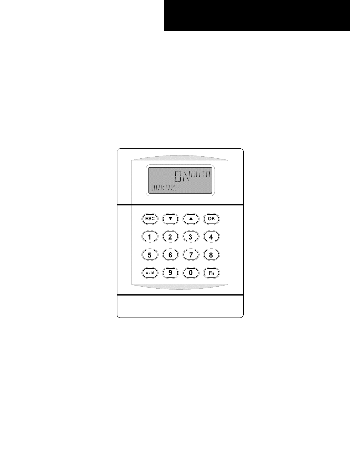
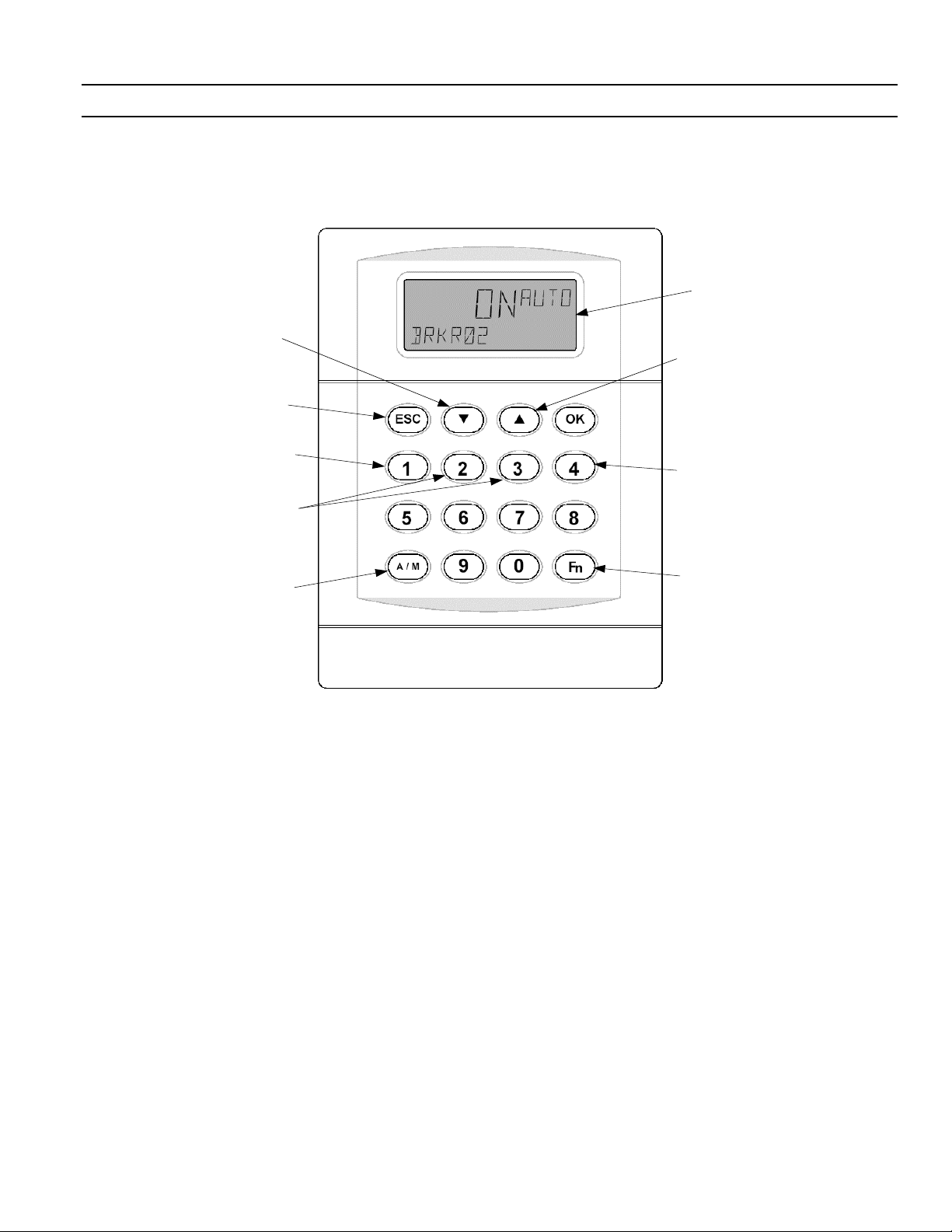
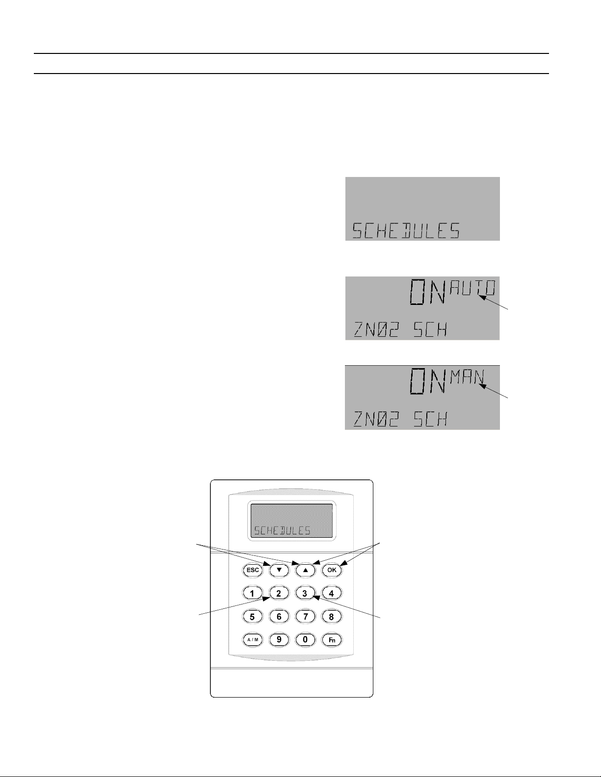
Programmer Layout
The key features of the Programmer are illustrated in
Figure 1.
Down arrow key moves
through menus and
decreases valuses.
ESC key rejects changes
and moves to previous
menu levels.
Chapter 1 – Navigating the Keypad and Display
LCD
Up arrow key moves
through menus and
increases valuses.
All number keys
are used for their
numeric values.
2 and 3 keys are
used within the Set
Schedule menu.
A/M key switches
between auto and
manual modes.
Figure 1. Key features of programmer keypad and display.
Navigating the Programmer
Menus
The top four keys of the LCD keypad are used to
navigate the controller menus, as follows:
• Press the
programmer menus, accept selections, or make
value changes.
• Press the up or down arrow keys to navigate
through the main menus or submenus. The
down arrow scrolls from the first item to the
last and then rolls over to the beginning when
all menus have been viewed. The up arrow
does the opposite, scrolling back from the last
menu item to the first.
• Press the
menu or to initiate a user logoff from the main
menu.
OK key to enter the desired
ESC key to go back to a previous
4 key is used within
the Calendar menu to
delete a date.
Fn key is only used
within certain menus
to access special
functions.
1
Page 6
A Series® Lighting Controller Programmer
Chapter 2 – Logging In and Out of the Programmer
Programmer Default Screen
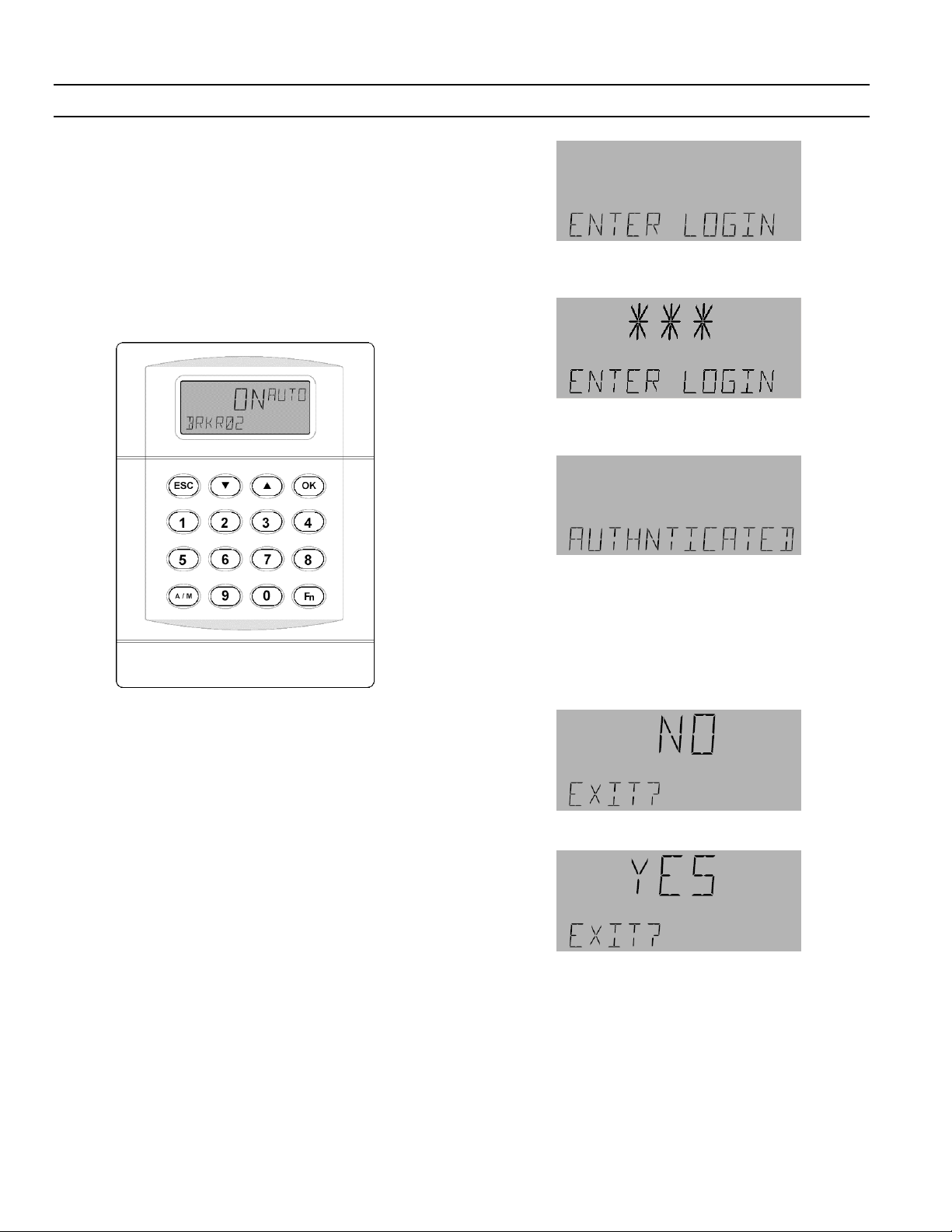
Figure 2 is a representation of the default Programmer
display (also shown on the front cover). It is also the
display that appears when the programmer has timed
out. The LCD screen is configured to show a rotating
display of the breaker (BRKR01–BRKR66) values.
Pressing any key on the keypad activates the
backlighting for a default time of 30 seconds. When a
user has logged in, the keypad stays backlit until he or
she logs off.
2. Enter the appropriate password for the desired
level of access using the Programmer keypad:
3. The Programmer displays the following when the
password is approved:
Figure 2. Display and keypad of the Lighting Controller Programmer.
Login
The programmer provides a secure connection into the
network and requires logging in to access its functions.
The ability to login and make changes to the
programmer is based on permissions. If a password is
approved, then a user has access to the appropriate
level of system menus. If the password is not approved,
the programmer returns to the default display, as
shown in Figure 2.
The two levels of permission are as follows:
• Edit Level – Default password 4129 gives full
edit mode access to the system.
• Display Level – Default password 1234 gives
access to view mode only.
To login to the Programmer for the first time:
1. Press
OK to bring up the Login display:
You can now access the menu selections appropriate to
your level of access.
Logout
To logout of the Programmer:
1. Press
2. Use the arrow keys to select YES:
3. Press OK to return to the default display.
ESC until the display appears as follows:
Timeout Mode
Timeout Mode occurs after the default value of 15
minutes. If there is no activity during that time, the
Programmer logs out automatically. No user input is
required for this timeout to occur, and any changes
made before the Programmer timed out will remain.
2
Page 7
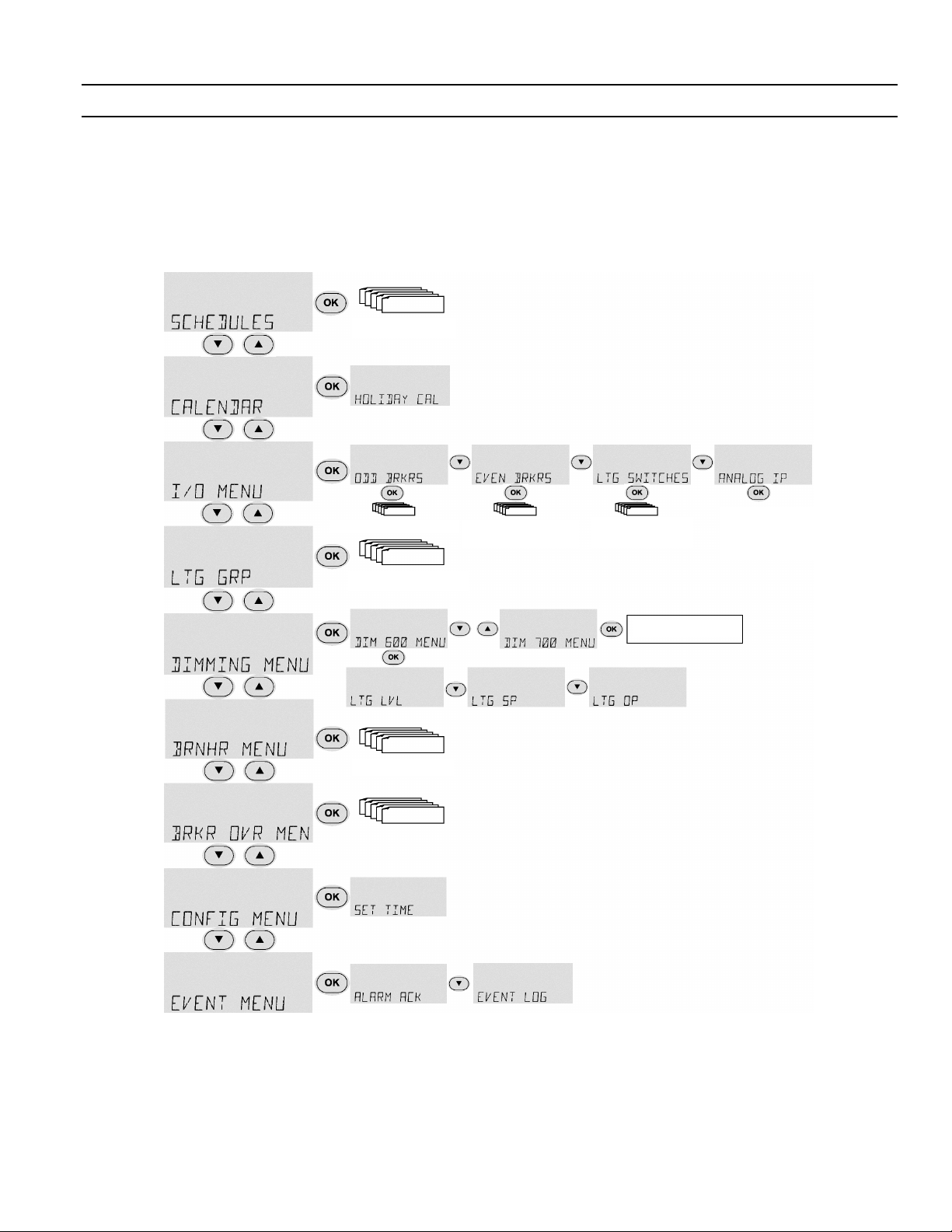
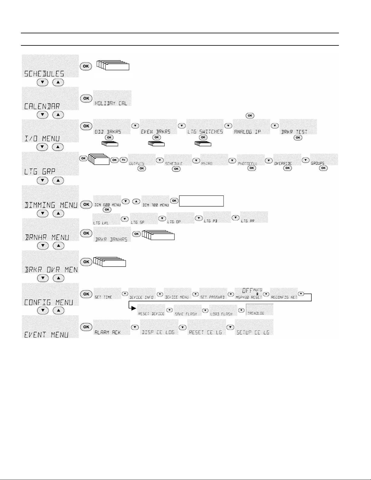
Menu Sequences
The following diagrams are a representation of the
menus within the programmer. Figure 3 shows the
menu sequence for display-only mode and Figure 4
shows the menu sequence for full-edit mode.
Schedules 1–16
A Series® Lighting Controller Programmer
Chapter 3 – Menu Structure
Odd Brkrs 01–65
Lighting Grps 1–16
Brkr BrnHrs 1–66
Brkr Ovrd 1–66
Even Brkrs 02–66
Ltg Switches
01–502
Same as DIM 600
Analog IP 01–03
LTG LVL 601–608
LTG LVL 701–708
Figure 3. Menu structure of lighting controller programmer, display-only mode.
3
Page 8
A Series® Lighting Controller Programmer
Chapter 3 – Menu Structure
Schedules 1–16
Analog IP 01–03
LTG LVL 601–608
LTG LVL 701–708
Odd Brkrs 01–65
Lighting Grps 1–16
Brkr BrnHrs 1–66
Brkr Ovrd 1–66
Even Brkrs 02–66 Ltg Switches 01–502
BO 1–66
Ltg Grps 1–16
SCH 1–66
MI101–512
BV2001–2066
Same as DIM 600
AI 1–3,
601–608,
701–708
MI101–512
BV2001–2066
MI101–512
BV2001–2066
Ltg Grps
1–16
Figure 4. Menu structure of lighting controller, editor mode.
Menu Descriptions
Following are brief descriptions of the menus and the
functions they provide.
Schedules
This function views or edits Zn 1–16 schedules and turns
them on or off manually. Up to eight turn on and off
times can be scheduled per day for each day of the week
and two calendar references.
Calendar
This function views or edits the Calendar reference, which
is used to select days of the year. Calendar is referenced in
the schedule object and when the controller date matches
the calendar date, the schedule follows the calendar on
and off times.
I/O Menu
These menu items view and/or edit the inputs and
outputs.
4
Page 9

A Series® Lighting Controller Programmer
Chapter 3 – Menu Structure
Odd Breakers. The odd breakers are those numbered 1, 3,
5, …, 65. These functions provide the following:
• Commissioning
• Manually turning on or off
• Linking override inputs
• Assigning override times
• Enabling event logging for breaker on, breaker
off, tripped breaker, and command failure
• Direct/reverse feedback setting
• Enabling flick warning
• Setting the time of flick warning
• Determining the status of the odd breakers
Even Breakers. The even breakers are those numbered 2,
4, …, 66. These functions provide the same operations as
those of Odd Breakers.
Lighting Switches. This function is used to manually turn
the switches on or off and to commission them.
Analog Input. This function finds the value/status of the
three analog inputs on the controller and to commission
them.
Breaker Test. This function tests the breakers for a set
time.
Lighting Group
These menu items are used to view or edit Zn 1–16 groups
and to turn them on or off manually.
Outputs. This function links breakers and/or lighting
groups to the group output. It also assigns a specific switch
input (analog or digital) to each breaker or group.
Schedule. This function turns the group on and off
according to a set schedule.
Astro. This function links Astro time to turn the group on
and off.
Photocell. This function turns the group on and off with
analog or digital inputs.
Override. This function overrides the group from off to
on for a set time.
Groups. This function turns the group on or off when all
nested groups turn on or off, following OR logic.
Dimming Menu
These menu items are used to view and/or edit the
dimming modules that can be optionally attached to the
product (Linknet devices 6 and 7) to control the lighting
ballast. The input to these modules is a photocell (AI)
and the output is the analog output (AV).
Dim Mod 600 Submenu. These functions adjust each
control loop for dimming module 1 with Linknet device 6.
There are eight control loops on a board and each
consists of the following functions:
• Ltg Lvl (input) – the input from the photocell
• Ltg SP – the set light level
• Ltg OP
• Ltg PB (controller PB) – the proportional gain of
the feedback loop
• Ltg RR (controller rest rate) – the integral gain of
the feedback loop
Dim Mod 700 Submenu. These functions are the same as
Dim Mod 600 but for Linknet device 7.
Burn Hours Menu
This function is used to view and/or reset the breaker
burn/run hours for an individual breaker.
Breaker Override Menu
This function views the Override BV for each breaker.
Override is used to turn an individual breaker on for a set
time and then shut it off. It is used for integration but not
by default.
Configuration Menu
These menu items are used to configure the lighting
controller and system.
Set Time. This function sets the time and date of the
controller.
Device Information. This function provides information
about the device, such as the device name, model number,
firmware version build, and software version.
Device Menu. This function sets up the location and
daylight savings time.
Set Password. This function sets the password for the
current user.
Reset MSP430. This function resets the back plane of the
controller. Note that this item should only be used for
instant remapping of the breaker or for diagnostic
purposes.
Reconfig Net. This function reconfigures the controller’s
address using DNA. This is done when the controller is
first connected to the network; since it is a subnet device, it
inherits the address of the master above. For example, if
the master address is 100 and the address of the subnet is
1, Reconfig Net sets the address to 101.
Reset Device. This function performs a hardware reset of
the controller.
Save Flash. This function saves the changes made to flash
memory so they can be reloaded if the battery goes dead
or to return to the previous version.
Load Flash. This function loads the database with the last
version saved to flash memory. It overwrites the current
contents of the database and performs a hardware reset.
5
Page 10

A Series® Lighting Controller Programmer
Chapter 3 – Menu Structure
Event Menu
These menu items are used to acknowledge alarms, view
battery status, view or reset the CE Log, and set up the CE
Log. The CE log captures the events listed in Table 1.
Event Display
Alarm ALARM
Alarm Acknowledged ALARM ACK
Dead Battery DEAD BATT
Dead Battery Restored DEAD BATT RESTORED
Command Failure CMD FAIL
Command Fail Restored CMD FAIL RESTORED
Status ON STATUS ON
Status OFF STATUS OFF
Under Voltage UNDER VOLT
Under Voltage Restored UNDER VOLT RESTORED
Reset DEV RESET
Time / Date change TIME CHG
DB Load DB LOAD
DB Save DB SAVE
DB Clear DB CLEAR
Lnk Online DEV ONLINE
Lnk Offline DEV OFFLINE
Breaker Trip BREAKER TRIP
Breaker Trip Restored BREAKER TRIP RESTORED
No events occurred NONE
Table 1. Events captured in the CE Log.
6
Page 11

A Series® Lighting Controller Programmer
Chapter 4 – Menu Functions
Display-Only Mode
The display-only mode is used to view information on
specific objects. The objects that can be displayed are:
• Analog and multistate inputs
• Binary outputs
• Analog and binary variables
• Lighting group
• Schedules
• Calendars
• Binary totalizers
• Compact event log
• Device
To view information about an object, use the four keys at
the top of the keypad as follows:
• Press the up and down arrow keys to navigate to a
specific menu; press
within the menu.
• Press the arrow keys to navigate to the desired
properties submenu (if there are more than one);
press
OK to view the data for the object.
• Press
ESC at any time to return to the previous
menu.
OK to view the first object
8. When finished editing, press the
A/M key to return to
auto mode.
Special Functions – Fn Key
Some objects have values that are accessed by pressing the
Function (
These objects and functions are listed in Table 2.
Output(s)
Multi-State
Schedule(s) Set Schedule
Calendar(s) Set Calendar
Fn) key on the lower right corner of the LCD.
Object Use Fn key to set these values:
Binary
Analog
Input(s)
Input(s)
Lighting
Group(s)
Commissioned YES/ NO
Direct/Reverse Acting
Override, Flick Warn, and Event Enable
Commissioned YES/ NO
Commissioned YES/ NO
Set Outputs, Schedule, Astro, Photocell,
Override, Groups
Table 2. Edit mode functions accessible with Fn key.
Edit Mode
Edit mode is used to change the values of objects. An
object must be placed in manual mode before it can be
edited. An object in manual mode stays in manual until
changed back to auto mode. Manual mode overrides any
control sequence.
To edit the value of an object, do the following:
1. Press the up and down arrow keys to navigate to a
specific menu; press
the menu.
2. Press the arrow keys to navigate to the desired
properties submenu (if there are more than one);
OK to edit the data for the object.
press
3. If the object has special functions (see below), press
Fn key to access them.
the
4. If the object is in auto mode, press the
place it in manual mode.
5. Use the keypad to adjust the object’s value as follows:
• Use the up and down arrow keys to adjust a binary
value (Yes/No, Off/On).
• Use the numeric keys to set an analog value; the
up and down arrow keys set the value to positive
or negative.
6. Press
OK to accept the change.
7. Use the arrow keys to scroll to the next item to
change or press Esc to return to the previous menu.
OK to view the first object within
A/M key to
7
Page 12
A Series® Lighting Controller Programmer
w
Chapter 5 – Schedules Menu
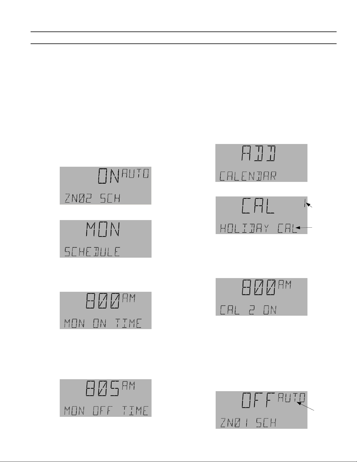
The Schedules menu is used to control and configure the
16 lighting schedules, ZN01 SCH to ZN16 SCH. These
schedules can be operated in manual or auto mode;
manual mode has highest priority. The Schedules menu is
used to add, edit, and delete
On and Off times, and to add
calendar references. One calendar reference can be added
to any one schedule.
Navigating the Schedules Menu
The Schedules menu and the special functions of several
of the keys are illustrated in Figure 5. The following items
relate to setting schedules:
• Use the arrow keys to scroll directly to a specific
day of the week, an existing CAL reference, or to
Add CAL.
• If no adjustments are made to a specific day of the
week, pressing 3 moves to the next day of the
week.
• Press the number 2 key at any point to go back to
a previous selection.
• On/Off times are not accepted into the schedule
unless they are modified. To keep a displayed
time the same, adjust it using the arrow keys up
one minute, back down one minute, and then
press 3 to accept the change.
• Schedules that contain more that one set of
On/Off time blocks in a single day cannot
overlap. However, the time blocks can be
scheduled side by side.
For example, one set of time blocks can start at
A.M. and stop at 4:00 P.M. The next set time
8:00
blocks can start at 4:01
P.M. and stop at 5:30 P.M.
Manually Adjusting a Schedule
Any of the 16 schedules, ZN01 SCH to ZN16 SCH, can be
manually turned on and off independent of the time and
day setting of the schedule. Do the following to manually
operate the schedule:
1. Navigate to the Schedules menu and press
2. Use the arrow keys to view all schedules and press OK
to select a specific schedule.
3. Press the A/M key to change to manual mode.
OK.
Flashing
Flashing
Hold the OK key in
Arrow keys scroll
through the days
of the week.
Press the 2 key to
return to a previous
selection.
Figure 5. Schedules menu and special key functions.
8
hle pressing the Up
arrow to adjust the
time.
Press the 3 key to
enter and edit On/Off
times and to accept
schedule changes.
Page 13
A Series® Lighting Controller Programmer
Chapter 5 – Schedules Menu
4. Press the down arrow key to change On to Off or the
up arrow key to change Off to On, and then press
to accept the change.
5. Press
OK again, followed by the A/M key, to return to
auto mode.
OK
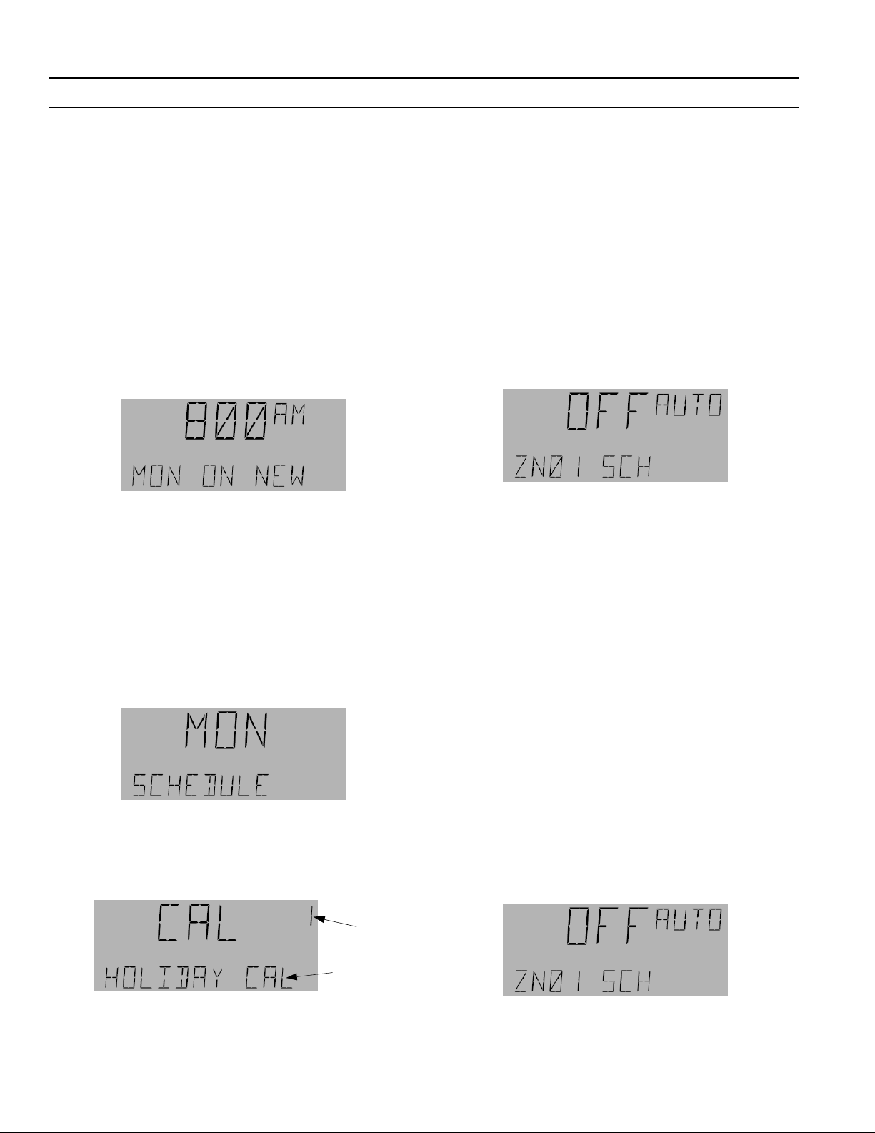
Adding On/Off Times to a
Schedule
Use the following procedure to add On and Off times to a
schedule:
1. From the Schedules menu, use the arrow keys to
navigate to the desired schedule. If the schedule is in
manual mode, press the
mode.
2. Press the OK and Fn keys to enter the schedule.
A/M key to change to auto
8. Press 3 to accept the Off time and return to the
display in step 2, so that additional time blocks can
be added to the day. Press 3 again to go to the next
day of the week and continue adding On/Off times.
Adding a Calendar Reference to a
Schedule
After Sunday, the LCD screen displays CAL to add up to
two Calendar references to a schedule.
1. Use the arrow keys to scroll through the days of the
week until the LCD displays the following:
2. Press OK to add a calendar reference:
Calendar
Reference
Number
Calendar
Name
3. Use the down arrow to scroll to a specific day of the
week, and then press 3 on the number keypad to add
a new On time. The time (8:00 AM) flashes when
adjustable.
4. Hold down the OK key while pressing the up arrow
key to adjust the hour.
5. Use only the up and down arrow keys to adjust the
minutes.
6. Press 3 to accept the On time and switch to setting
the Off time.
3. Press OK to add the CAL reference number.
4. When the CAL reference number is flashing, adjust
the reference number using the arrow keys.
5. Press
6. While the time is flashing, adjust the On/Off times as
OK to accept the changes; the LCD screen
moves to the CAL On time:
in the previous section for setting Schedule times.
Editing On and Off Times in a
Schedule
Use the following procedure to edit On and Off times:
1. Use the arrow keys to navigate to the desired
schedule, then press
OK to edit that schedule:
7. Adjust the hours and minutes as in steps 4 and 5.
Flashing
9
Page 14
A Series® Lighting Controller Programmer
Chapter 5 – Schedules Menu
2. Press the Fn key to use the Set Schedule function.
On/Off times are not accepted into the schedule
unless they are modified. To keep a displayed time
the same, adjust it using the arrow keys up one
minute, back down one minute, and then press 3 to
accept the change.
3. Use the arrow keys to scroll to the time blocks for that
day.
4. Press the 3 key to edit a time block.
5. Hold down the
key to adjust the hour of the On time.
6. Use only the arrow keys to adjust the minutes.
7. Press 3 to accept the change and then repeat the
process to edit the Off time. When the Off time is
accepted, the option to enter a new On time appears:
8. Add a New time block as explained above or press 3
to go to the next CAL/DAY. The LCD screen displays
the next day. Continue to edit times or press
twice to exit the Schedules menu.
OK key while pressing the up arrow
ESC
Editing a Calendar Reference in a
Schedule
Use the following procedure to edit a calendar reference:
1. Use the arrow keys to scroll to the desired schedule
and press
OK. Press Fn to enter the schedule:
5. Press 3 to accept the change and then repeat the
process to edit the Off time.
6. Press 3 to accept the changes and press
exit the Schedules menu.
ESC twice to
Deleting On and Off Times in a
Schedule
To delete time blocks in a schedule, set the On time to the
same time as the Off time for a specific day of the week.
Once these changes have been accepted, the controller
deletes that time block automatically.
1. Navigate to the desired schedule and press the
key:
2. Press the Fn key and scroll with the arrow keys to the
desired day of the week.
3. Press the 3 key to adjust that day. Keep pressing 3
until the time block to be deleted appears.
4. Hold down the
to adjust the hour; release the
the arrow keys to adjust the minutes so that the On
time matches the scheduled Off time for that time
block.
5. Press 3 to accept the changes; the LCD screen
displays the next time block, if there is any, or it
shows a new On time. Press 3 again to advance to the
next day.
6. Continue deleting times, or press Esc twice to exit the
Schedules menu.
OK key while pressing the arrow key
OK key and use only
OK
2. Use the arrow keys to scroll though the days of the
week until the LCD screen displays the calendar
reference and press
number flashes. Press
schedule.
3. Hold down the OK key while pressing the up arrow
key to adjust the hour of the On time.
4. Use only the arrow keys to adjust the minutes.
OK. The calendar reference
OK again to edit the calendar
Calendar
Reference
Number
Calendar Name
Deleting Calendar References in
a Schedule
A calendar reference can be deleted by setting the
reference number to 0.
1. Navigate to the desired schedule, and press the
key:
2. Press the Fn key and scroll with the arrow keys to the
desired day of the week with the Cal reference on the
screen.
10
OK
Page 15

A Series® Lighting Controller Programmer
3. Press OK; the calendar reference flashes.
4. Use the down arrow to set the reference number to 0
and press
5. The previous submenu (Add Calendar) appears;
press Esc to return to the Schedules menu.
OK to delete that calendar reference.
Chapter 5 – Schedules Menu
11
Page 16
A Series® Lighting Controller Programmer
Chapter 6 – Calendar Menu
The Calendar menu is used to add, edit, and delete dates
in either of two calendars. The calendar can be operated
in either auto or manual mode.
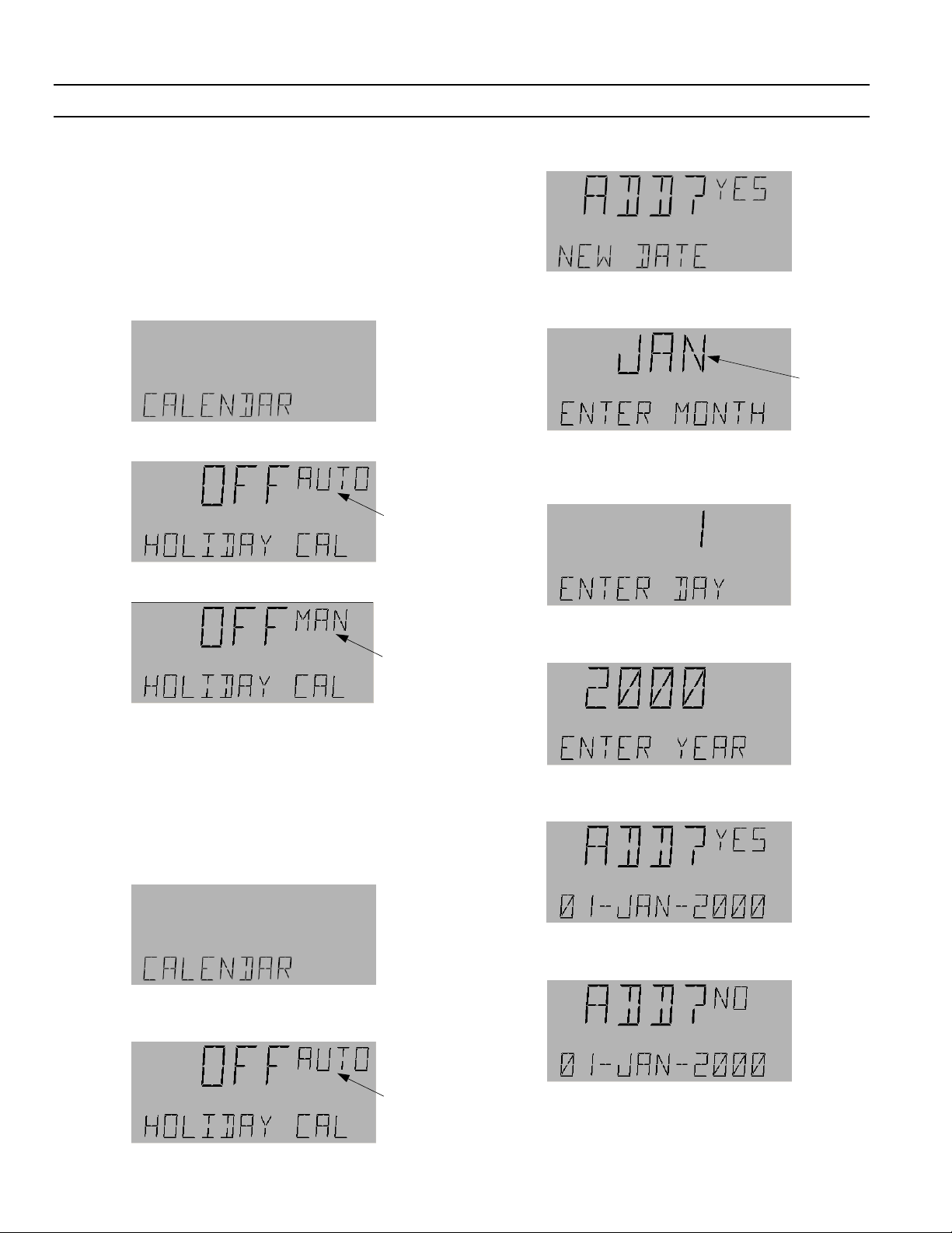
Manually Operating a Calendar
Calendar objects can be operated in manual mode, as
follows:
1. Use the arrow keys to navigate to the Calendar menu.
2. Press OK for the following display:
Flashing
3. Press the A/M key to change to manual mode:
3. Press the Fn key for the New Date display:
4. Press OK for the month display. Use the arrow keys to
change to the desired month.
Flashing
5. Press OK to accept the month and switch to the day
of the month display. Use the arrow keys to select the
desired date.
Flashing
4. Use the arrow keys to change to ON or OFF status.
OK to accept the change.
Press
5. Press
A/M to return to and OK to accept auto mode.
Adding Dates to a Calendar
Use the following procedure to add dates to a calendar:
1. Use the arrow keys to navigate to the Calendar menu.
2. Press OK for the following display. If the object is in
manual mode, switch to auto by pressing the
A/M key.
6. Press OK to accept the day and switch to the year
display. Use the arrow keys to select the desired year.
7. Press OK to accept the year and switch to the Add?
display. Press
Otherwise, use the down arrow to select Add No and
OK to reject the change.
press
OK to accept the date.
Flashing
8. Add all desired dates to the calendar and then use
the arrow keys to view them. Exit the Calendar menu
by pressing the
12
ESC key.
Page 17
A Series® Lighting Controller Programmer
Chapter 6 – Calendar Menu
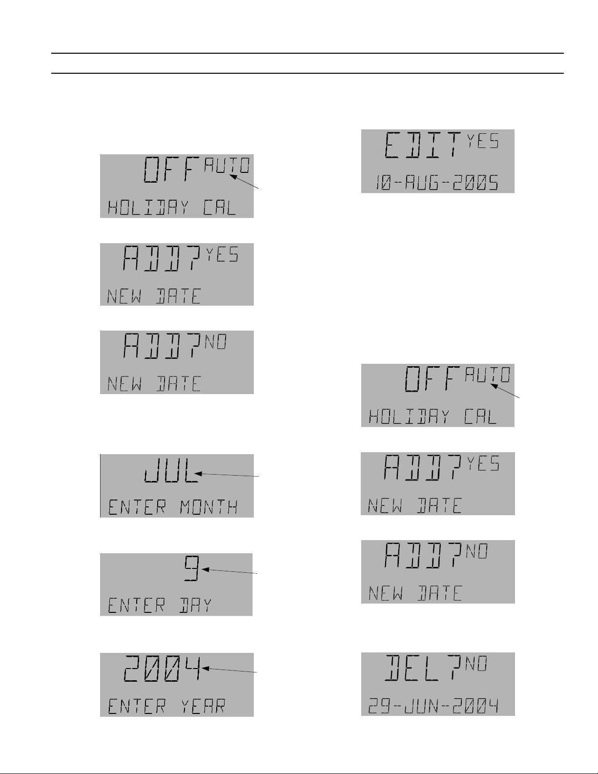
Editing Calendar Dates
Use the following procedure to edit a calendar date:
1. At the Calendar menu, press
display:
2. Press the Fn key for the following display:
3. Press the down arrow key to select No:
OK to reach the OFF
Flashing
8. Press the arrow keys to change to the desired year
and press
appears:
9. Do one of the following:
• If the date is correct, press
• If the date is incorrect, press the down arrow key
to change to No and then press
change.
10. Press
menu.
OK to accept it. The following display
OK to accept it.
OK to reject the
Esc as needed to return to the desired previous
Deleting Calendar Dates
Use the following procedure to delete a calendar date:
1. At the Calendar menu, press
display:
OK to reach the OFF
4. Press OK to display the first Calendar date and press
the arrow keys to scroll through the dates.
5. Press
6. Press the arrow keys to change the month. Press OK
7. Press the arrow keys to change the day. Press OK to
OK when the desired date appears to display the
month:
Flashing
to accept the new month and display the day:
Flashing
accept the new day and display the year:
Flashing
Flashing
2. Press the Fn key for the following display:
3. Press the down arrow key to select No:
4. The first date added is displayed. Press the arrow keys
to scroll to the date to be deleted.
5. Press the 4 key for the Delete display:
13
Page 18

A Series® Lighting Controller Programmer
Chapter 6 – Calendar Menu
6. Press the down arrow key to change to Yes:
7. Press OK to delete the date.
8. Press
Esc as needed to return to the desired previous
menu.
14
Page 19

A Series® Lighting Controller LCD Programmer
Editing Binary Outputs
Note that if any breaker is not physically present, this is
indicated by a special symbol on the display:
Chapter 7 – I/O Menu
Breaker 23
is not
present
If any breaker is not present in the database of the
controller, it is indicated as follows:
Use the following procedure to edit binary breaker
outputs.
1. Use the arrow keys to scroll to the I/O menu, the
press
OK twice to display the odd breakers
(numbered 1, 3, …, 65) submenu. If the even
breakers (numbered 2, 4, …, 66) are desired, press
OK and the down arrow to advance to that
submenu from the I/O menu.
2. Press the arrow keys to scroll to the desired breaker
output (BO) and press
OK to edit:
If the breaker is not commissioned, this is
indicated on other displays by the special symbol
shown:
Breaker 01
is not
commissioned
6. Press the arrow keys to change between No and
Yes. Press
OK to accept the change and display the
Reverse Acting screen:
7. Press the arrow keys to change between No and
Yes. Press
OK to accept the change and display the
Override screen:
Flashing
3. Do one of the following:
• Press the
Fn key to go to the Commissioned
screen of the BO (skip to step 5).
• Press the
A/M key to put the object in manual
mode and then use the arrow keys to command
the BO On or Off. Press the
OK key to execute
the command.
4. If the BO is in manual mode, press
OK to make the
MAN symbol flashing (if it is not flashing). Press
A/M key to change from manual to auto mode
the
and press
procedure by pressing
OK to accept the change. Exit the
Esc to return to the main
menu.
5. If the
Fn key was pressed in step 3, the
Commissioned (with either No or Yes) screen
appears:
15
8. Do one of the following (each is described below):
• Press
OK to edit the Override.
• Press the down arrow key once to go to the
Flick Warn submenu:
• Press the down arrow key twice to go to the
Event Enable submenu:
Page 20

A Series® Lighting Controller Programmer
Chapter 7 – I/O Menu
Editing Override
The Override function is used to command a Binary
Output On from the Off condition, for a set time, and
then to command it Off by relinquishing control of
override. Override references can be BV and MI, both
local and remote. If Override references indicate BI and MV,
they should be ignored. The Override time can be set from
1 to 240 minutes, with a default of 120 minutes.
Use the following procedure for editing Overrides:
1. Navigate to the Override menu and press
edit:
2. Use the arrow keys to change BV to MI:
3. Do one of the following:
• Press
OK, use the numeric keys to change to the
desired value, and press
OK to accept the
change.
• Press
Fn to display the panel number. Use the
numeric keys to change to the desired panel
number:
OK to
Flashing
5. Press OK to edit:
Flashing
6. Press the arrow keys or numeric keys to adjust the
value of the override time. Press
OK to accept the
change.
7. Press
ESC to return to the Override menu:
Press the down arrow key to jump to the Flick
Warn menu or the up arrow key to jump to the
Event Enable menu.
Editing the Flick Warning
Flick Warn is used to warn people in a lighting area
that the lights are going to turn off. Flick warn occurs
for 1–2 seconds immediately after a schedule expires,
which is user selectable from 1 to 240 minutes.
Do the following to edit Flick Warn:
1. From the Flick Warn submenu press
displays on the LCD screen and Flick Warn On,
scrolls across the bottom, depending on the
current value. Press
OK to edit:
OK. Yes or No
Press OK to accept the change:
4. The Override time display appears:
Flashing
2. Use the arrow keys to select Yes or No.
Flashing
3. Press OK to accept any change. If Flick Warn is
enabled, the Flick Time is displayed:
16
Page 21

A Series® Lighting Controller LCD Programmer
4. Press OK to adjust the time. Use the number
keypad to adjust a Flick Time from 1–240 minutes.
Flashing
5. Press OK to accept the change. Press ESC and then
the down arrow to continue to Event Enable.
Editing Event Enable
Event Enable is used to enable the breaker events to be
captured in compact event log. Use the following
procedure to edit Event Enable:
1. From the Event Enable submenu press
OK.
Chapter 7 – I/O Menu
5. The Command Failure submenu is displayed;
OK to edit.
press
YES or NO CMD FAIL enables or disables the
recording (in the CEL) of the CMD event A CMD
event occurs when the breaker is ON and it is
commanded to turn OFF.
6. Use the arrow keys to select No or Yes. Press
accept any change.
7. No or Yes Breaker Trip is displayed; press
edit.
Breaker Trip enables or disables the recording (in
the CEL) of a breaker going to trip position from
ON.
8. Use the arrow keys to select No or Yes. Press
accept any change; the menu rolls back to the
Status On screen.
OK to
OK to
OK to
2. Press OK to edit; YES or NO STATUS ON appears
on the display.
YES/NO STATUS ON enables or disables,
respectively, the recording (in the CEL) of a
breaker when it changes to ON.
3. Use the arrow keys to select No or Yes and then
OK. Press OK again to edit.
press
YES/NO STATUS OFF enables or disables,
respectively, the recording (in the CEL) of a
breaker when it changes to OFF condition.
4. Use the arrow keys to select No or Yes. Press
accept any change.
OK to
9. Use the arrow keys to scroll through the changes
or press
submenu. Press
desired previous menu.
ESC to return to the Event Enable
ESC as needed to return to the
Lighting Switches
Lighting switches are maintained and momentary
switches mounted on the standard/remote input
expansion board. Maintained switches are defined by
the states ON, OFF, and N/A. N/A means that the
switch is not present on the board. Momentary switches
are toggling switches. When the switch is turned on, it
toggles its state. There are 66 switches, LTG SW
101–116, 201–216, 301–316, 401–416, and 501–502.
LTG SW 101–116 are mounted on the standard input
expansion module which is on the main controller and
LTG SW 201–216, 301–316, 401–416, and 501–502 are
controlled from the remote expansion module. (Please
refer to DEH41083 for further information). Each
17
Page 22

A Series® Lighting Controller Programmer
Chapter 7 – I/O Menu
switch can be configured in the maintained (tristate)
or momentary configuration. If the expansion board is
not connected to the system, a
symbol appears on
the display to indicate that the input is not physically
present in the system.
Editing Multistate Inputs
Use the following procedure to edit a multistate input:
1. Navigate to the Lighting Switches menu and press
OK.
2. Use the arrow keys to scroll to the desired MI and
then press
OK to edit.
Flashing
6. Press OK to accept the change; auto mode the
switch is indicated. Go to step 12.
7. If the Fn key is pressed, COMMISSIONED with NO
or YES flashing displays on the LCD screen. When
an object is not commissioned, then no events or
alarms are logged. When an object is
commissioned, events and alarms are logged as
selected.
Flashing
or
Flashing
Do one of the following:
• Press the
A/M key to change the switch to
manual mode; continue with step 3.
• Press the
Fn key to access the special functions;
jump to step 7.
3. If the
A/M key is pressed, MAN and the value flash
on the display:
Flashing
4. Use the arrow keys to adjust the value to OFF/ON
or N/A. (Note that, in manual mode, the items
displayed depend on the type of switch. If the
switch is the toggle type, it will display only ON
and OFF. If the switch is the maintained type, it
will indicate OFF, ON and N/A.) Press
OK to
accept the changes.
5. Press
OK again, followed by the A/M key to return
to auto mode.
8. Press the arrow keys to adjust the Commissioned
status to YES or NO. If the switch is not
commissioned, the
symbol appears on the
display.
9. Press
OK to accept the changes. The following
screen appears:
Flashing
This option (MIC) configures the switch as a
multistate maintained switch. Do either of the
following:
• Press
OK to accept the switch as a multistate
maintained switch.
• Press up the arrow key twice to move to the
next option:
Flashing
Flashing
18
Page 23

A Series® Lighting Controller LCD Programmer
Chapter 7 – I/O Menu
This option (STEP) configures the switch as a
toggle switch. Press
OK to accept the choice.
10. The following screen may appear:
Flashing
Do one of the following:
• If switch is to be configured as a toggle switch,
OK.
press
• If the switch is to be configured as a
maintained switch, press numeric key 1. The
following display appears:
Flashing
Press OK to accept the change.
11. The following is displayed:
connected to the system, then its analog input
displays the
symbol.
Do one of the following:
• Press the
A/M key to adjust the AI value
manually; continue with step 3.
• Press the
Fn key to access the special functions;
jump to step 6.
3. If the
A/M key is pressed, the following display
appears:
Flashing
4. Use the number keys to set the desired value and
OK to accept the change.
press
12. Press ESC as needed to return to the desired
previous menu.
Editing Analog Inputs
The analog input menu is used to get the values of
sensors on the analog input ports (AI1–AI3) of the
controller. ANALOG IP01 corresponds to AI1, IP02 to
AI2, and IP03 to AI3. It is also used to get the light level
signal generated by the dimming module (LTG LVL
601–615 and 701–715). (Please refer to the dimming
module user’s guide, DEH41085, for further
information.)
Use the following procedure to edit analog inputs:
1. Navigate to the ANALOG IP (AI) and press
2. Use the arrow keys to scroll to the desired AI and
then press
OK to edit. Note that if the board is not
OK:
Flashing
5. Press OK followed by the A/M key to put the AI
back into Auto Mode. Press
OK to accept change to
AUTO mode. Go to step 8.
6. If the Fn key is pressed, the Commissioned menu
appears, with NO or YES flashing. When an object
is not commissioned then no events or alarms are
logged. When an object is commissioned, events
and alarms are logged as selected.
7. Press the arrow keys to adjust Commissioned to
YES or NO. If NO is selected,
display. Press
OK to accept the changes.
appears on the
19
Page 24

A Series® Lighting Controller Programmer
Chapter 7 – I/O Menu
8. Press ESC as needed to return to the desired
previous menu.
Breaker Test
The breaker test is used to toggle the breaker output for
test time (test time can be adjusted in the device
submenu of the Configuration menu) and then
relinquish the breaker.
To edit Breaker Test, use the following procedure:
1. Navigate to the Breaker test menu and press
2. Press the A/M key to change to manual mode:
OK.
Flashing
Flashing
3. Press the arrow keys to change from off to on or
vice versa:
Flashing
4. Press OK to accept changes and switch to auto
mode:
20
Page 25

A Series® Lighting Controller LCD Programmer
The Lighting Group menu is used to control and
configure the 16 lighting groups, ZN01 to ZN16. These
groups can be operated in auto and manual modes;
manual mode has higher priority. A group indicates
fault mode if the switch is linked to the group is not in
the network. For example, if the switch MI101 has been
linked to the group ZN16 LTG GRP and the Linknet
device (standard expansion board) is not in the
network, the group indicates a fault condition, as
shown:
Fault
Symbol
Within each Lighting Group (ZN01 to) menu there are
six main submenus:
• Outputs
• Schedule
• Astro
• Photocell
• Override
• Groups
The following sections describe how to set up a lighting
group and access the six submenus.
Chapter 8 – Lighting Group Menu
Flashing
4. Press the A/M key to switch to manual mode:
Flashing
5. Use the arrow keys to change OFF to ON or ON to
OFF and press
6. To return to auto mode, press OK, followed by the
A/M key and OK again:
OK to accept the change:
Manual Mode Operation
To operate a group in manual mode, do the following:
1. Navigate to the Lighting Group menu:
2. Press OK to display the first lighting group (ZN01):
3. Use the arrow keys to scroll to the desired group
and press
Group 2 (ZN02 LTG GRP) is selected, the display
is as follows:
OK to select it. For example, if Lighting
7. Press ESC as needed to return to the desired
previous menu.
Outputs
Lighting Outputs can be either local or remote
references of Binary Outputs (BOs) or Lighting Groups
(LGs). The Programmer is used to tell the LG what
lighting outputs (BO/LG) to control. (Note that
Lighting Groups cannot reference themselves.) With
each output a local or remote switch can be linked. The
switch can be a physical one (MI type) or a binary
variable (BV), whose values can be changed with the
keypad. The BV variables are accessible using the
Breaker Override menu of the Programmer.
The switch controls individual breakers/group On and
Off. For each lighting output entered, an optional
switch can be assigned to control the individual breaker
On and Off. Switch references to BI and MV should be
ignored.
21
Page 26

A Series® Lighting Controller Programmer
Chapter 8 – Lighting Group Menu
Viewing Outputs and Switches
1. Navigate to the Lighting Group menu:
2. Press OK to display the first lighting group (ZN01):
7. Continue to use the arrow keys to scroll through
the lighting outputs and their associated switches.
• If no switch is associated with a particular
output, then the following display appears:
3. Use the arrow keys to scroll to the desired lighting
group and then press
4. Press the Fn key to display the Outputs submenu:
5. Press OK to display the first output.
If there are no outputs, the following message is
displayed; jump to step 8.
OK to select it:
Flashing
Flashing
8. After the last output/switch is displayed, the
display requests a new output:
9. Do one of the following:
• Press
• Press the down arrow to go back to the first
• Press
OK and then follow the procedure for
adding outputs and switches (described in the
next subsection).
output and use the arrow keys to scroll through
the outputs and switches again.
ESC to exit to the Outputs submenu.
Adding an Output
Use the following procedure to add an output:
1. Navigate to the desired lighting group and press
OK.
Flashing
6. Press the down arrow key to view the switch
associated with the selected output:
2. Press the Fn key to display the Outputs submenu:
3. Press OK to add a new output:
22
Page 27

A Series® Lighting Controller LCD Programmer
Chapter 8 – Lighting Group Menu
Flashing
4. Do one of the following:
• Press
OK to accept a BO object type and jump
to step 8.
• Use the arrow keys to adjust the output type
and press
OK to accept it and jump to step 8.
• Press the Fn key to edit the panel number and
continue with step 5.
5. When the Panel number flashes, use the number
keys to adjust the panel number.
Flashing
6. Press OK to accept the change:
or
Note that to delete any Output or Switch, set the
output instance to 0 and then press
OK.
Adding a Switch
Use the following procedure to add a switch to a new
output:
1. Use the arrow keys to navigate to the newly added
output:
2. Press the down arrow to reach the NO SWITCH
display:
Flashing
7. Use the arrow keys to change the object type from
BO to LG Group or vice versa and press
OK when
the desired object appears on the screen.
8. Once the object type is accepted, the instance
number flashes:
Flashing
9. Do one of the following:
• Use the arrow number keys to change the
instance number. Press
OK to accept the
instance number and add the object.
• Use the arrow keys to set the number to 0 to
delete the output.
23
3. Press OK to add a switch:
Flashing
4. Press the arrow keys to select either the BV or MI
(the BI and MV options should be ignored, as they
do not exist in the system).
5. Do one of the following:
• Press
• Press the
OK to accept a BV or MI object type.
Fn key to edit the panel number.
When the panel number flashes, use the
number keys to adjust it.
Page 28

A Series® Lighting Controller Programmer
Chapter 8 – Lighting Group Menu
Flashing
6. Press OK twice to accept the change; the instance
number flashes:
Flashing
References to BI and MV in the input schedule should be
ignored.
Viewing a Schedule
Use the following procedure to view Schedule on and
off times:
1. Navigate to the desired lighting group and press
OK to select it:
Flashing
7. Do one of the following:
• Use the arrow or number keys to change the
instance number and then press
the change:
• If the switch input is to be deleted, use the
arrow keys to set the instance number to 0.
OK to delete the input.
Press
8. The next output of the group is now displayed:
OK to accept
2. Press Fn to display the Outputs submenu:
3. Press the down arrow key to display the Schedule
submenu:
4. Press OK to display the Schedule input:
9. Press the down arrow once to view the switch
associated with that output.
Schedule
Lighting Groups can be scheduled to turn lights On
and Off. During holidays, lights are not normally
turned On or Off according to the normal schedule.
Holidays are set in the system by using the Calendar
object that is linked to the schedule object. The
schedule can be a local or remote schedule (SCH) or
Binary Variable (BV) and multi-input (MI) reference.
If there is no input, the following is displayed:
5. Use the arrow keys to view the schedule values.
24
Page 29

A Series® Lighting Controller LCD Programmer
Chapter 8 – Lighting Group Menu
or
Editing a Schedule Input
To link a lighting group On or Off using a schedule, do
the following:
1. Navigate to the Schedule submenu under the
Group menu as explained above:
2. Press OK to display the schedule input:
6. Do one of the following:
• Use the up and down arrow keys to accept a
schedule, a binary variable, or a multi-input
(MV or BI references should be ignored) as a
schedule reference, and then press
OK to
accept the change. Jump to step 8.
or
or
3. Press OK to edit the schedule input.
• If there is no input, the following is displayed:
Press OK twice to add a Schedule input.
4. The following is displayed:
Flashing
5. Press up arrow key to move to the following
display:
Flashing
• Press the Fn key to edit the panel number.
When the Panel number flashes on the LCD
screen, use the number keypad to adjust the
panel number. Continue with step 7.
Flashing
7. Press OK to accept the change; SCH starts flashing.
Flashing
8. Use the arrow keys to select the type of schedule
and press
OK.
9. When the Schedule is accepted, the instance
number flashes on the LCD screen. Do one of the
following:
25
Page 30

A Series® Lighting Controller Programmer
Chapter 8 – Lighting Group Menu
14. Press OK to accept any change.
15. Press
ESC to return to the schedule submenu.
Flashing
• Use the arrow or number keys to change the
instance number.
• Press
• Use the arrow keys and set the number to zero
10. The following display appears; press OK. Lights
On allows the lighting group to turn on with the
schedule.
11. When Yes is flashing, use the arrow keys to select
Yes or No. Press
12. The following display appears; press OK. Lights
Off allows the lighting group to turn off with the
schedule.
OK to accept the instance number and
add the object.
to delete this Schedule instance:
OK to accept the changes.
Deleting a Schedule
Use the following procedure to delete a schedule
reference:
1. Navigate to the desired schedule:
Flashing
2. Set the output instance number to 0 and press OK
to accept the change.
Astro
The Astro menu is used to enable an Astro Calculation
to decide whether the lighting group is turned off at
sunrise (Astro Off) and/or if the lights are turned on at
sunset (Astro On). Based on controller location, Astro
On is calculated by sunset time minus an offset; e.g.,
night time. Astro Off is calculated by sunrise time plus
an offset; e.g., morning.
To use the Astro function, Set Latitude/Longitude for
the location must be calculated in the object, and the
Universal Time Coordinate (UTC) Offset must be
enabled with an accurate Offset calculation. The UTC
should be set with the time zone list or by entering the
time as a manual offset in ±hours to one decimal place.
Apart from this there are locations given in the
Programmer (Config. menu), which can be selected by
using the arrow keys. The selection of the location
automatically adjusts the DST, UTC, and latitude and
longitude of the location.
13. When Yes is flashing, use the arrow keys to select
Yes or No:
Enabling Astro On and Off
1. Navigate to the desired Lighting group submenu
and press
26
OK.
Page 31

A Series® Lighting Controller LCD Programmer
Chapter 8 – Lighting Group Menu
2. Press the Fn key, navigate to the Astro submenu
with the arrow keys:
3. Press OK to display Astro On No or Yes:
4. Do either of the following:
• Press
OK to edit the value.
8. Press
OK to accept the changes; Astro Off No or
Yes is displayed.
9. Do either of the following:
• Press
OK to edit the value.
Use the arrow keys to select Astro Off Yes or No,
and then press
OK to accept changes.
Flashing
Use the arrow keys to select Astro On Yes or No
and then press
OK to accept the change.
• Use the down arrow key to view the offset if
Astro On is already enabled.
5. The default value of On Offset 30 (setting range is
0–240) is displayed on the LCD screen.
6. Press OK to edit the On Offset.
Flashing
• Use the down arrow key to view the offset if
Astro Off is already enabled.
10. The default value of OFF Offset 30 (the setting
range is 0–240) is displayed. Press
OK to edit the
OFF Offset.
Flashing
11. Use the number keys to edit the OFF Offset
numerical value. Use the arrow keys to make the
offset subtractive or additive. Press
OK to accept
the changes.
12. Press
ESC to return to the Astro submenu.
7. Use the number keys to set the numerical value of
the offset and the arrow keys to make the offset
time minus or plus.
27
Page 32

A Series® Lighting Controller Programmer
Chapter 8 – Lighting Group Menu
Photocell
The Photocell menu is used to control the lighting
group On or Off via a photocell (light level). The
Photocell input reference can be local or remote
AV/AI/BV/MI/MV/BI. BI and MV references should be
ignored.
Viewing the Photocell Input
1. Navigate to the desired lighting group submenu
and press
2. Press the Fn key and navigate to the Photocell
submenu using the arrow keys.
OK.
5. Press ESC to return to the Photocell submenu or
use the following procedure to edit the Photocell
input.
Editing the Photocell Input
When editing the Photocell input, MI, AV, BV, and AI
can be selected, depending upon the requirement.
1. Navigate to Photocell menu:
3. Press OK to display either of the following:
• If there are no inputs, the LCD screen displays
the following:
• If there is an input, the input type, input name,
and instance number are displayed:
Instance
No.
Input
Name
4. Use the arrow keys to view whether Lights On and
Lights Off are enabled.
2. Press OK to display the photocell reference. (This
example shows an analog photocell.)
If there is no photocell reference, the following is
displayed:
3. Press OK and use the arrow keys to select the object
type (AI, MI, BV and AV). BI and MV should be
ignored.
or
4. When the desired object type is selected, press OK.
The type of object will flash.
28
Page 33

A Series® Lighting Controller LCD Programmer
Chapter 8 – Lighting Group Menu
Flashing
5. Press the Fn key to change the panel number (if a
reference to the remote panel photocell inputs is
needed) with the numeric keys. Press
OK to accept
the new panel number.
Flashing
6. The object type flashes. Press OK to accept the
object type.
Flashing
7. The object instance flashes. Use the arrow keys to
change the instance number.
Flashing
The Lights On feature enables or disables
photocell control for turning the lighting group
on. If no change is required, press the arrow key to
go to the Lights Off menu.
10. If the input is an AI and Lights On is enabled,
then On When LT/EQ scrolls across the display.
Press
OK to adjust this value using the number
keys. Press
OK to accept the change. The analog
inputs are defined as percentages. (For example, if
the jumper on the controller is set for 5 V, then the
range 0–5 V range is indicated as 0–100%)
The display may show the following:
11. Press OK to adjust the Lights Off Yes/No value.
Press OK to accept the changes and switch to the
Lights On display:
8. Press OK to adjust the Lights On Yes/No value.
Flashing
9. Use the arrow keys to change the setting and press
OK to accept it.
29
Flashing
12. Use the arrow keys to change the setting and press
OK to accept the change.
The Lights Off feature enables or disables
photocell control for turning the lighting group
Off.
13. If the input is an AI and Lights Off is enabled,
then the Off When GT/EQ scrolls across the
display. Press OK to adjust this value using the
number keypad and press
OK to accept any
changes.
Page 34

A Series® Lighting Controller Programmer
Chapter 8 – Lighting Group Menu
14. Use the Arrow keys to scroll and review the
changes or press
submenu.
ESC to return to the Photocell
Override
The Override function is used to command a Lighting
Group On from the Off condition for a set time, and
then to command it Off by relinquishing control.
Override references can be BV, MI, BI, MV, both local
and remote. Any reference to BI and MV should be ignored.
The Override time can be set from 1 to 240 minutes.
The default value is 120 minutes.
Viewing Override
Use the following procedure to view override times:
1. Navigate to the desired lighting group and press
OK.
5. Press ESC to return to the Override submenu.
Adding an Override Input
Use the following procedure to add an Override input:
1. Navigate to the desired lighting group and press
OK.
2. Press the Fn key and use the arrow keys to navigate
to the Override menu:
3. If there are currently no inputs, the following
display appears:
2. Press the Fn key and use the arrow keys to navigate
to the Override menu:
3. Press OK to display the Override input:
4. Press the arrow keys to view the Override time
(1–240 minutes):
4. Press OK and then use the arrow keys to select the
object type (BV, MI).
Flashing
or
Flashing
5. Press the Fn key to edit the panel number. Press
the numeric keys to change the panel number (if a
30
Page 35

A Series® Lighting Controller LCD Programmer
remote object reference should be made) and
press
OK to accept the changes.
6. Press OK. Use the arrow keys to edit the object
number and press OK to accept the changes.
7. The Override time is displayed. Press
the override time.
OK to edit
Flashing
Chapter 8 – Lighting Group Menu
Flashing
5. Use the arrow keys to change the override input
type:
Flashing
or
8. Use the arrow keys to change the value and press
OK to accept the change.
9. Press
ESC to return to the Override submenu.
Editing an Override Input
Use the following procedure to edit an Override input:
1. Navigate to the desired lighting group and press
OK.
2. Press the Fn key and use the arrow keys to navigate
to the Override menu:
3. Press OK to display the Override:
Flashing
6. Press the Fn key to edit the panel number:
Flashing
7. Use the numeric keys to change the panel number
and press
OK. The input type flashes again:
Flashing
8. Press OK to edit the Instance number:
Flashing
4. Press OK to edit the override input:
31
9. Use the arrow numeric keys to change the instance
number and press
OK to display the Override time:
Page 36

A Series® Lighting Controller Programmer
Chapter 8 – Lighting Group Menu
10. Press OK to edit the Override time.
Flashing
11. Use the arrow keys or the number keypad to adjust
the time, up to 240 minutes:
Flashing
12. Press OK to accept the changes.
13. Press
ESC to return to the Override submenu.
Groups
The Groups function is used for common areas so that
lights stay on when any one of the nested Lighting
Groups is on. Lights stay on until all the nested groups
are OFF and the off time delay times out. Note that if a
Schedule, Photocell, Astro, or Override turns the group
on, then the group remains on.
4. Press the Fn key and press the down arrow key five
times to reach the Groups submenu:
5. Press OK to display the Group Off time:
6. Use the arrow keys to continue to scroll and view
all available groups.
Changing the Group Off Time
Use the following procedure to adjust the group Off
time.
1. Navigate to the Groups submenu as in the previous
procedure.
Viewing a Group
1. Navigate to the Lighting Group menu.
2. Press OK to display the first Lighting Group and
use the arrow keys to navigate to the desired
group.
3. Press OK and AUTO starts to flash:
Flashing
2. Press OK to display the Group Off time.
3. Press OK to edit the Group Off Time:
Flashing
4. Use the number keys to adjust the Group Off time,
and then press
OK.
32
Page 37

A Series® Lighting Controller LCD Programmer
Chapter 8 – Lighting Group Menu
5. Continue to scroll through the groups and make
any adjustments, or press
ESC to return to the
Groups submenu.
Adding a New Group
Use the following procedure to add a new lighting
group:
1. Navigate to the Groups submenu as in the previous
two procedures:
2. Press OK to display the Group Off Time:
3. Use the arrow keys to scroll through all the nested
groups. After the last group, Add New Group is
displayed. (This appears immediately if there are
no groups present.)
• Press the FN key to edit the panel number for a
remote LG.
Flashing
Use the numeric arrow keys to change the
panel number and press
OK key:
Flashing
5. Use the arrow keys to change the instance number
and press
OK to accept the changes.
6. Do either of the following:
• Press the down arrow to add another New
Group.
• Press
ESC to return to the Groups submenu.
4. Do either of the following:
• Press
OK to edit the LG instance number:
Use the arrow keys to select a different LG:
Flashing
33
Page 38

A Series® Lighting Controller Programmer
Chapter 9 – Dimming Menu
Scroll to the dimming menu with the arrow keys:
Viewing the 600/700 Series
Proportional
Band for
Feedback
Loop 1
6. Press the down arrow key to display the reset rate
for the feedback loop.
Daylight Optimization Modules
1. Press OK for the Dim 600 menu:
2. Press OK to display the input light level. This
example shows the input light level at input port 1
of Daylight Optimization Module 600:
Input Light
Level
3. Press the down arrow key to display the set light
level:
Set Light
Level
Reset Rate
for Feedback
Loop 1
7. Pressing the down arrow key further scrolls to next
object’s values. For example, this display indicates
the input light level at the input port 2 of Daylight
Optimization Module 600:
There are eight input ports and output ports and
their associated feedback loops on each Daylight
Optimization Module.
8. Press
ESC to return to the Dim 600 menu:
4. Press the down arrow key to display the output
value of the feedback loop, which goes to the
dimming ballast.
Output of
Feedback
Loop
5. Press the down arrow key to display the
proportional band value for the feedback loop.
9. Press the down arrow key to scroll to the Dim 700
menu:
10. Press OK and the arrow keys to view the different
objects of Daylight Optimization Module 700, as
above.
34
Page 39

A Series® Lighting Controller LCD Programmer
Editing the 600/700 Series
Daylight Optimization Modules
The following procedures are used to edit the various
objects of these Daylight Optimization Modules.
Chapter 9 – Dimming Menu
Flashing
Input Light Level
1. These objects can be edited by going to a
particular Light Level object (in the example
below it is 601) as explained above. Press
edit.
2. Press the A/M key to change to manual mode:
3. Press the numeric keys to set the desired value.
OK to accept the changes.
Press
OK to
Flashing
3. Press the A/M key to switch to manual mode.
Flashing
4. Use the numeric keys to set the desired value; in
this example, from 44.0 to 50.0:
Flashing
5. Press OK to accept the change. Press OK again,
followed by the
A/M key to return to auto mode:
Flashing
Flashing
4. To return the object (LTG LVL 601) to auto
mode, press
again by
5. Press the down arrow key to scroll to the Lighting
SP object.
OK, followed by the A/M key, followed
OK.
Set Light Level
1. Scroll to the LTG SP object; the display will be
similar to the following:
2. Press OK to edit the settings:
6. Press OK to complete the switch to auto mode.
7. Press the down arrow key will scroll to the LTG OP
object.
Lighting OP
The Lighting OP value is automatically generated by
the feedback loop.
Setting Lighting Feedback Loop Gain
1. Scroll to the LTG PB object, and press OK:
Flashing
35
Page 40

A Series® Lighting Controller Programmer
Chapter 9 – Dimming Menu
2. Press the A/M key to switch to manual mode:
Flashing
3. Use the numeric keys to set the desired value; in
this example, from 200 to 100.
Flashing
3. Press the A/M key to switch to mode.
Flashing
Flashing
4. Press OK to accept the change. Press OK again,
followed by the
A/M key to return to auto mode:
Flashing
5. Press OK key to make the switch to auto mode:
Note that unless you are familiar with the feedback
loop, it is advisable to not change the default
value.
6. Press down arrow key to go to the LTG RR object.
4. Press the numeric keys to set the desired value; in
this example, from 4 to 30:
Flashing
5. Press OK to accept the change.
6. Press OK again, followed by the A/M key to return
to auto mode:
Flashing
Setting Lighting Feedback Loop Rest Rate
1. Scroll to the LTG RR object; the display will be
similar to the following:
2. Press OK to edit the settings:
7. Press OK to make the switch to auto mode.
Note that unless you are familiar with the feedback
loop, it is advisable to not change the setting of the RR
object.
36
Page 41

A Series® Lighting Controller LCD Programmer
The Burn Hours menu is used to view and set the
number of hours a breaker is ON.
Viewing Breaker Burn Hours
1. Navigate to the Burn Hours menu:
2. Press OK to advance to the Breaker Burn Hours
submenu:
Chapter 10 – Burn Hours Menu
Flashing
4. Pres the A/M key to change to manual mode. Use
the number and arrow keys to change the setting:
5. Press ESC twice to return to the Burn Hours menu.
Resetting Breaker Burn Hours
1. Navigate to the Burn Hours menu:
3. Press OK and then use the arrow keys to view the
burn hours of the different breakers.
Editing the Breaker Burn Hours
1. Navigate to the Burn Hours menu:
2. Press OK to advance to the Breaker Burn Hours
submenu:
2. Press OK and use the arrow keys to advance to the
Reset Burn Hours submenu:
3. Press OK to reset a particular breaker:
Flashing
4. Use the arrow keys to scroll to the desired breaker,
then press
OK:
3. Use the arrow keys to scroll to the desired breaker
burn hours and press
OK:
37
Page 42

A Series® Lighting Controller Programmer
Chapter 10 – Burn Hours Menu
5. Do either of the following
• Press
• Use the arrow keys to change NO to YES and
6. Press ESC twice to return to the Breaker Burn
Hour menu.
OK to not reset the breaker burn hours.
press
OK to reset the breaker burn hours:
38
Page 43

A Series® Lighting Controller LCD Programmer
Chapter 11 – Breaker Override Menu
The Breaker Override menu is used to view and edit
the override binary variable. These variables can be
used to manually turn the breakers and groups on and
off. These variables are referred in the I/O menu with
the even and odd breakers as the override inputs.
Similarly, they can be used as switch inputs for the
outputs of the groups.
Viewing Override Objects
1. Navigate to the Breaker Override menu:
2. Press OK to view the first breaker’s override status.
Use the arrow keys to scroll through the remaining
override binary variable objects:
4. Use the upper arrow key to change to Override
mode. (Override mode turns the variable on,
normal mode turns the variable off.)
Flashing
5. Press ESC to return to normal mode.
Note that once the breaker is in override mode, it must
be returned to normal mode before it can be switched
again to override mode.
Editing Override Objects
1. Navigate to the Breaker Override menu:
2. Press OK to view the first breaker’s override status.
Use the arrow keys to scroll to a specific override
binary variable object:
3. Press OK and then the A/M key to change to
manual mode:
Flashing
39
Page 44
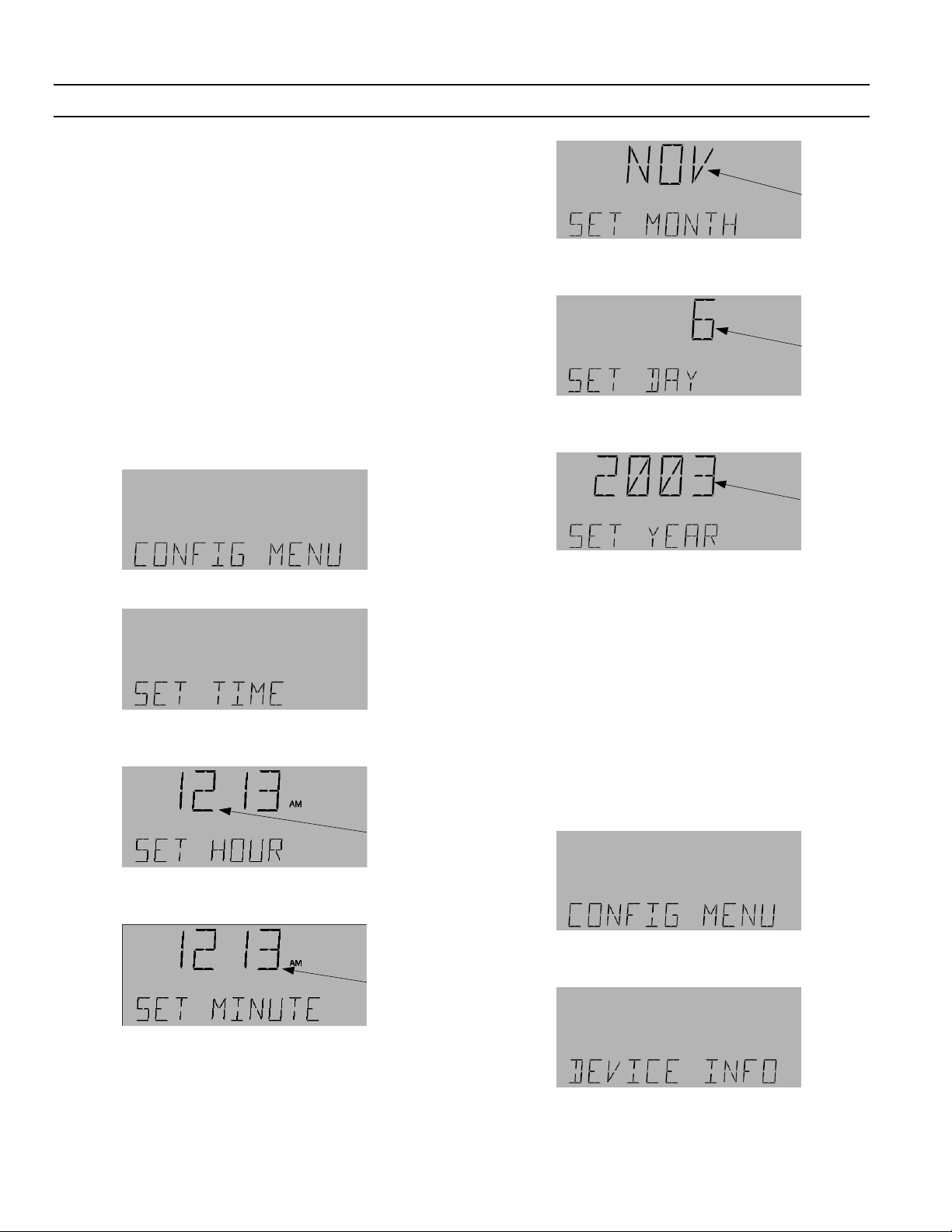
A Series® Lighting Controller Programmer
Chapter 12 – Configuration Menu
These functions are used to configure the lighting
controller.
Set Time
The Set Time menu is used to set the time and date on
the display and the network. When a command is
entered into the controller, the new time and date are
broadcast to the network so that all the devices
connected to that controller are set from this single
command.
This process is sequential: first the hour is set, then the
minute, month, day, and year. When setting the time
and date, to go to a previous menu press the
exit the Set Time menu, press the
Use the following procedure to set the time:
1. Navigate to the configuration menu:
ESC key.
A/M key; to
Flashing
6. Press OK to accept the month setting and then use
the arrow keys to adjust the day of the month:
Flashing
7. Press OK to accept the day setting and then use the
arrow keys to adjust the year:
Flashing
2. Press OK to display the Set Time submenu:
3. Press OK to display the current set time and use
the arrow keys to adjust the hour:
Flashing
4. Press OK to accept the new hour and then use the
arrow keys to set the minutes:
Flashing
8. Press OK to accept the year setting. Press ESC to
return to the Set Time menu.
Device Information
The Device Information menu displays information on
specific devices. The information that can be viewed is
the device name, model name, firmware version, and
application software information. When the text
contains more characters than fit on the display, the
text scrolls along the lower area of the LCD screen.
Use the following procedure to display Device
Information:
1. Navigate to the Configuration menu and press
2. Use the arrow keys to scroll to the Device Info
menu:
OK.
5. Press OK to accept the new minutes and then use
the arrow keys to adjust the month:
40
Page 45

A Series® Lighting Controller LCD Programmer
Chapter 12 – Configuration Menu
3. Press OK and then use the arrow keys to scroll
through the device information in the following
order:
• Device Name.
• Model Name.
• Firmware Version.
• Application Software Version.
Selecting a City
1. At the Device menu, press OK to access the
Location submenu:
2. Press the up or down arrow keys to scroll through
the list of regions, which appear in the following
order:
• Western USA
• Central USA
• Eastern USA
• Canada
• Central America
• South America
• Eastern Europe
• Western Europe
• Far East
3. when the desired region is displayed, press
display a list of cities in that region. Use the arrow
keys to scroll through the different cities which are
grouped in alphabetical order.
4. Press
OK to select the city where the system is
located; for example:
OK to
4. Press ESC followed by the down arrow key to
return to the Device menu.
Device Menu
The Device menu is used to select a city (for the time
zone), to enable Daylight Saving Time, Set Latitude
and Longitude, set UTC, and Breaker Test time.
Breaker test time feature is used along with breaker test
(explained in the I/O menu section).
From the Configuration menu, press
arrow twice to reach the Device menu:
OK and the down
5. Use the arrow keys to select YES to choose this city:
6. Press OK to set the latitude, longitude, DST, and
UTC for that particular city.
7. Press
In addition to choosing the city and automatically
setting its longitude and latitude, UTC, and DST, these
parameters can all be set manually (explained below).
41
ESC to return to the Device menu.
Page 46

A Series® Lighting Controller Programmer
Chapter 12 – Configuration Menu
Enabling or Disabling Daylight Saving
Time
The Enable/Disable DST menu is used to turn on or
off the DST function. DST must be enabled to use the
ASTRO function up.
1. From the Device menu, press the arrow keys to
scroll to the Enable DST submenu:
2. Press OK to view and/or edit the setting:
Flashing
3. Press the up arrow to change DST ENABLED to
YES if it is NO or press the down arrow to change
DST ENABLED to NO if it is YES:
3. Press OK to accept the changes and set the
longitude and use the arrow keys to select E or W.
Use the numeric keys to select the longitude value:
4. Press OK to accept the changes and return to the
Set Latitude and Longitude submenu.
5. Press
ESC to return to the Device menu.
Set UTC Offset
The Set UTC (Universal Time Coordinate) function
calculates accurate times for the Astro function. The
UTC Offset must be enabled with an accurate offset
calculation. The UTC is set either from the time zone
list or by entering the time as a manual offset in ± hours
to one decimal place.
1. From the Device menu, press the arrow keys to
scroll to the UTC Offset submenu:.
4. Press OK to accept any changes and return the
display the Enable DST menu.
5. Press
ESC to return to the Device menu.
Set the Latitude and Longitude
The Set Latitude/Longitude submenu is used to set the
Latitude and Longitude within the controller network.
This function must be set accurately for the Astro
function. The value can be set between latitude of 90° N
and S and longitude of 180° E and W.
1. From the Device menu, press the arrow keys to
scroll to the Set Latitude and Longitude submenu:
2. Press OK to set the latitude and select N or S using
the arrow keys. Use the numeric keys to set the
latitude value:
42
2. Press OK to view and/or edit the setting:
Flashing
3. Use the arrow keys to select Yes or No and then
OK to accept the selection:
press
4. If Yes is selected, use the up arrow (to increase)
and down arrow (to decrease) keys to change the
Offset values. These values increase or decrease in
Page 47

A Series® Lighting Controller LCD Programmer
increments of 0.5 hours from a maximum +12.0 to
a minimum –12.0 hours. The value flashes on the
LCD screen until accepted:
Chapter 12 – Configuration Menu
Flashing
5. Press OK to accept the changes and return to the
Set UTC submenu.
6. Press
ESC to return to the Device menu.
Setting the Breaker Test Time
The Breaker Test time submenu is used to set the
breaker test time in conjunction with the Breaker Test
function in the I/O menu.
1. From the Device menu, press the arrow keys to
scroll to the Breaker Test Time submenu:
2. Press OK to edit the test time:
2. Press OK to enter a new password:
3. Enter a four-digit password with the numeric
keypad:
4. When Confirm PW is displayed, re-enter the
password:
Flashing
3. Press the A/M key to switch the object to manual
mode:
Flashing
4. Use the numeric keys to change the test time (in
seconds) to the desired value and press
accept the change.
5. Press
ESC to return to the Device menu.
OK to
Setting the Password
The Set Password function is used to change the fourdigit numeric password for logging in to the network.
1. From the Device menu, press the arrow keys to
scroll to the Set Password submenu:
5. One of the following occurs:
• If the two numbers entered are the same, then
PW Reset is displayed, indicating that the
change has been accepted. Go to step 6.
• If the passwords do not match, Reset Fail is
displayed on the LCD screen. Press ESC or OK
and repeat the sequence for setting the
password.
6. Press OK or ESC to return to the Set Password
submenu.
7. Press
ESC to return to the Device menu.
43
Page 48

A Series® Lighting Controller Programmer
Chapter 12 – Configuration Menu
Reset the Controller Backplane
(MP 430)
This function resets the back plane of the controller.
Note that it should only be used instant remapping of
the breaker is needed or the breaker is remapped for
diagnostic purposes.
1. From the Configuration menu, use the arrow keys
to scroll to the MSP430 RESET menu.
2. Press OK to start the edit:
7. Press ESC to return to the Configuration menu.
Reconfigure Network
The Reconfigure menu is used to resolve address
conflicts when installing new control equipment onto a
network. Each device uses information from its DIP
switch settings and from the other devices on the
network to determine its proper address. The
Reconfigure function changes the addresses of devices
so that they can communicate on the network.
1. From the Configuration menu, use the arrow keys
to scroll to the Reconfigure Network submenu:
Flashing
3. Press the A/M key to change to manual mode:
4. Press the up arrow key to change OFF MAN to ON
MAN:
5. Press OK to reset the MSP430 and turn off the
function:
2. Press OK to display the following:
Flashing
3. Use the arrow keys to select Yes or No”
4. Press OK to accept the changes and start the
configuration:
6. Press OK key twice to jump to return to auto mode:
44
5. When the reconfiguration is complete, the display
returns to the Reconfigure Network submenu.
6. Press
ESC to return to the Configuration menu.
Page 49

A Series® Lighting Controller LCD Programmer
Reset Device
The Reset Device function is used to reset the
controller.
1. From the Configuration menu, use the arrow keys
to navigate to the Reset Device submenu.
2. Press OK for the following display:
3. Press OK to activate the reset function. Use the
arrow keys to change Yes to No or No to Yes.
Chapter 12 – Configuration Menu
3. Use the arrows keys to select Yes or No:
4. Do either of the following:
• Select YES and press
appears until the function is complete:
OK. The following display
Flashing
Flashing
or
Flashing
4. Press OK to accept the changes and return to the
default display.
5. You must log in again to access additional menus.
Save to Flash
The Save to Flash menu is used to save the database to
controller Flash memory.
1. From the Configuration menu, use the arrow keys
to scroll to the Save to Flash menu:
• Select No and the previous menu is displayed.
5. When the Save is complete, the LCD screen
returns to the Save Flash menu.
6. Press
ESC to return to the Configuration menu.
Load from Flash
The Load from Flash menu is used to load the saved
database to the controller from flash memory.
1. From the Configuration menu, use the arrow keys
to scroll to the Load Flash menu:
2. Press OK for the following display:
Flashing
2. Press OK for the following display:
3. Use the arrow keys to select Yes or No.
4. Do either of the following:
• Select YES:
45
Page 50

A Series® Lighting Controller Programmer
Chapter 12 – Configuration Menu
Press OK to start loading the database from
flash memory:
• Select No:
Flashing
Press OK to return the display to the Load Flash
menu.
5. When Loading is complete, the LCD screen
returns to the default display. You must log in
again to access additional menus.
Trendlog Configuration
1. From the Configuration menu, use the arrow keys
to scroll to the Trending configuration menu:
2. Press OK for the following display:
46
Page 51

A Series® Lighting Controller LCD Programmer
The Event menu is used to view and reset event entries
and to set the size of event buffer. They are also used to
enable and disable the alarm output for different
conditions, such as device status, time change, lighting
alarm, and lighting status and to acknowledge the
alarm output. Acknowledging the alarm output turns
off the alarm relay, which is triggered in response to the
device status change (device goes offline, device reset,
dead battery, and undervoltage), time change (time of
the controller changes), lighting status (breaker turns
on or off), and lighting alarms (breaker is tripped or
there is a command failure).
The events listed in Table 3 are displayed on the
Programmer. Events are displayed beginning with the
most recent events. A maximum of 2000 events can be
viewed at a time.
Event Display
Alarm ALARM
Alarm Acknowledged ALARM ACK
Dead Battery DEAD BATT
Dead Battery Restored DEAD BATT RESTORED
Command Failure CMD FAIL
Command Fail Restored CMD FAIL RESTORED
Status ON STATUS ON
Status OFF STATUS OFF
Under Voltage UNDER VOLT
Under Voltage Restored UNDER VOLT RESTORED
Reset DEV RESET
Time / Date change TIME CHG
DB Load DB LOAD
DB Save DB SAVE
DB Clear DB CLEAR
Lnk Online DEV ONLINE
Lnk Offline DEV OFFLINE
Breaker Trip BREAKER TRIP
Breaker Trip Restored BREAKER TRIP RESTORED
No events occurred NONE
Table 3. Events captured in the CE log.
Chapter 13 – Event Menu
4. Press OK to reach the following display:
5. Press OK and AUTO flashes:
Flashing
6. Press the A/M key to put into manual mode and
press the arrow key until ACK is displayed. Press
OK to acknowledge the alarm.
7. Press ESC to exit to the Event submenu.
8. The Alarm Acknowledge submenu returns to the
default auto mode without further user input.
Acknowledging an Alarm
Use the following procedure to acknowledge an alarm:
1. Press any key on the keypad to silence the alarm.
2. Press OK and then login using the appropriate
password.
3. Use the arrow keys to navigate to the Event menu:
Displaying the CE Log –
Viewing Events
Use the following procedure to view an event:
1. Navigate to the Event menu with the arrow keys:
47
Page 52

A Series® Lighting Controller Programmer
Chapter 13 – Event Menu
2. Navigate to the Display CE Log menu with the
arrow keys:
3. Press OK to display the following event
information:
Time
• Use ARROW keys to change NO to YES:
Object
ID
4. Use the arrow keys to scroll through the different
events.
Note that the month and day display as four digits. In
the example above, November 5th is displayed as 11 5.
Month
and Day
Event
Type
Reset the CE Log
1. Navigate to the Event menu with the arrow keys:
2. Navigate to the Reset CE Log submenu with the
arrow keys:
3. Press OK for the following display:
Press OK to reset the CE log:
The Reset CE Log display returns the reset is
complete:
5. Press ESC to return to the Event menu.
Set Up the CE Log
Logged events can be edited from the Event menu.
Events are stored in Compact Event Logs (CEL), with a
default buffer size of 2000 events. CELs can be set to
hold from 1–2000 events. CELs can be enabled or
disabled for the following: device status, time change,
lighting alarms, and lighting status.
1. Navigate to the Events menu:.
4. Do either of the following:
• Press
OK to not reset the CE log:
2. Press OK and use the arrow keys to scroll to a
specific Setup CE Log:
48
Page 53

3. Press OK to display the current buffer size:
4. To edit the buffer press OK:
A Series® Lighting Controller LCD Programmer
Chapter 13 – Event Menu
• Use the arrow keys to scroll to the next category
if no change is required.
• To edit press
Yes or No and then press
change.
10. The Lighting Alarms display is next. Lighting
alarms consists of breaker trip and command
failure.
Flashing
OK. Press the arrow key to adjust
OK to accept the
5. Use the numeric keypad or arrow keys to enter the
new buffer size.
6. Press
OK to display Device Status. Device status
consists of dead battery, reset device, device
offline, or undervoltage.
7. Do either of the following:
• Use the arrow keys to scroll to the next category
if no change is required.
• To edit press
OK. Press the arrow key to adjust
Yes or No, and then press OK to accept the
change.
8. The Time Change display appears next:
11. Do either of the following:
• Use the arrow keys to scroll to the next category
if no change is required.
• To edit press
Yes or No and then press
OK. Press the arrow key to adjust
OK to accept the
change.
12. The Lighting Status display appears. Lighting
status consists of status on and status off.
13. Do either of the following:
• Use the arrow keys to scroll to the next category
if no change is required.
• To edit press
Yes or No and then press
OK. Press the arrow key to adjust
OK to accept the
change.
9. Do either of the following:
49
Page 54

A Series® Lighting Controller Programmer
Chapter 13 – Event Menu
14. Press ESC to return to the Setup CE Log display.
50
Page 55

A Series® Lighting Controller LCD Programmer
Analog Input (AI) – An analog input is denoted by an AI
object. The four types are 10 K, 5 V, 10 V and 4–20
mA, and are selected by the jumper location on the
controller board.
Analog Variable (AV) – The analog variables types are
LTG SP, LTG OP, LTG PB, and LTG RR
Binary Output (BO) – A binary output is denoted by a
BO object. It is output for different breaker.
Binary Totalizer (BT) – A binary totalizer is denoted by a
BT object. It gives the cumulative ON time of a BO
object.
Binary Variable (BV) – A binary variable is denoted by a
BV object. It is used to assign binary values to an
object.
Calendar (CAL) – A calendar is denoted by a CAL object.
It is used to define holidays.
Compact Event Log (CEL) – A compact event log is
denoted by a CEL object. It is used to register events
and generate alarms.
Lighting Group (LG) – A lighting group is denoted by an
LG object. It is used to create a group of binary
objects and link them to different switches, groups,
schedules, and analog inputs.
Multistate Input (MI) – A multistate input is denoted by
an MI object. It is used to accept the lighting switch
inputs.
Schedule (SCH) – A schedule is denoted by an SCH
object. It is used to create schedules for different
lighting groups (LG objects).
Glossary
51
Page 56

g
GE Consumer & Industrial
General Electric Company
41 Woodford Ave., Plainville, CT 06062
DEH41082 R01 0804 © 2004 General Electric Company
 Loading...