

Page 1
g
p
g
quip
y
Application
These instructions apply to bolt-on circuit breaker kits
with catalog numbers AMCB6GB and AMCB4GB.
For use with circuit breaker types SGH, SGL and SGP.
For use with circuit breaker cover kit AFP4SGD.
Installation
WARNING: Danger of electrical shock or injury.
OFF
Turn
switchboard before workin
e
Equipment is to be installed and maintained b
properly trained and qualified personnel only.
ower ahead of the panelboard or
inside the
ment or removing any component.
DEH40129 Installation Instructions R03
Spectra Series™ Power Panelboards
Bolt-On Circuit Breaker Kits
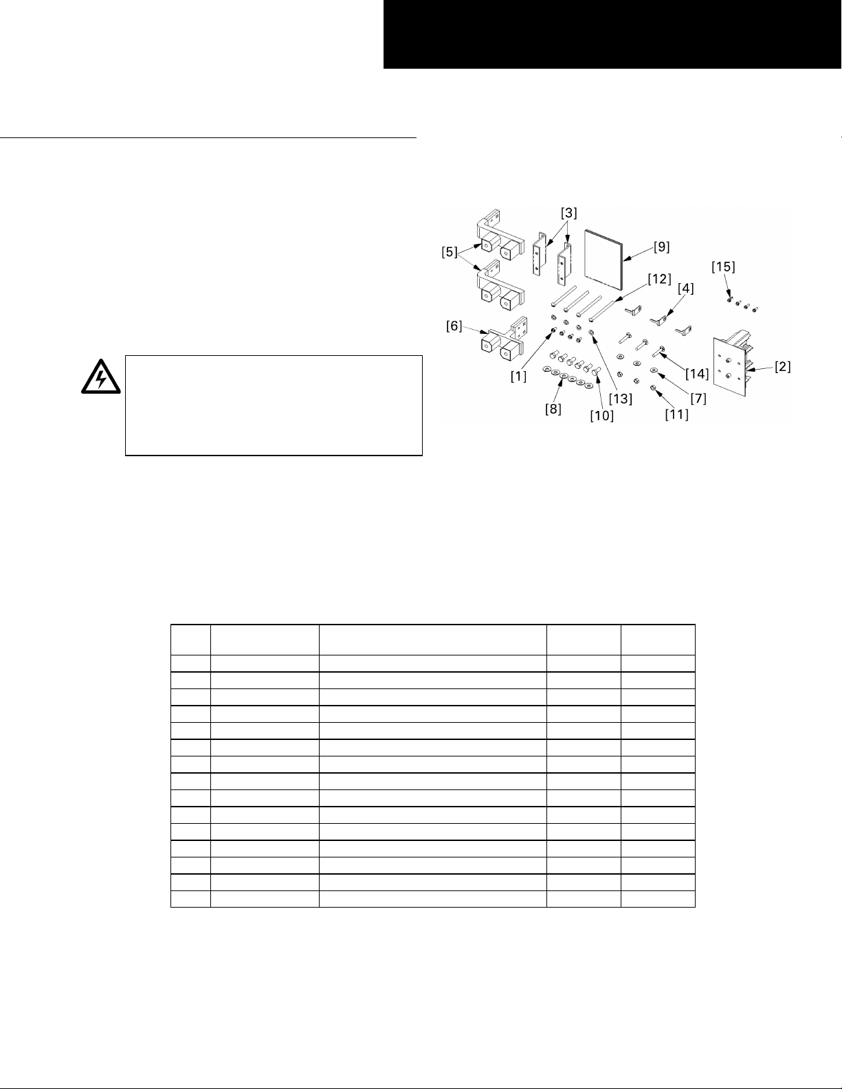
Figure 1. Parts included in the kits AMCB4GB and AMCB6GB.
In the following instructions numbers in brackets in the
text and figures refer to the items in Table 1.
1. Confirm the contents of the kit. These kits are used to
install double-branch G-frame Spectra circuit breakers
into Spectra APNB bolt-on–style interiors. The vertical
space required for each kit is 5.50 inches (4X).
Figure 1 illustrates the parts included in this kit, which
are listed in Table 1.
Item Part # Description
1 192A6976P189 Thread-forming screw, #10-32 x 7/16"44
2 252B3575P1 Circuit breaker mounting bracket 2 2
3 208C2291P1 Filler center 2 2
4 252B3613P1 Antiturn clip 2 3
5 252B3618G10 G Frame double strap 2 2
6 252B3618G11 G Frame double strap 1 1
7 75A105503P101 Conical spring washer, 1/4" 44
8 75A105503P105 Conical spring washer, 5/16" 46
9 DEH40129 Installation instructions 1 1
10 N22P23012B6 Hex-head bolt, 5/16-18 x 3/4" 46
11 N245P21B6 Nut, 1/4-20 2 3
12 N37P21969B6 Machine screw, 1/4-20 x 33/4" 44
13 N402P11B6 Flat washer, 1/4" 44
14 N657P21024B6 Carriage bolt, 1/4-20 x 11/2" 23
15 N730BP1308B6 Thread-forming screw, #6 x 1/2" 44
Table 1. Parts list for kits AMCB4GB and AMCB6GB.
Qty. in
AMCB4GB
Qty. in
AMCB6GB.
Page 2
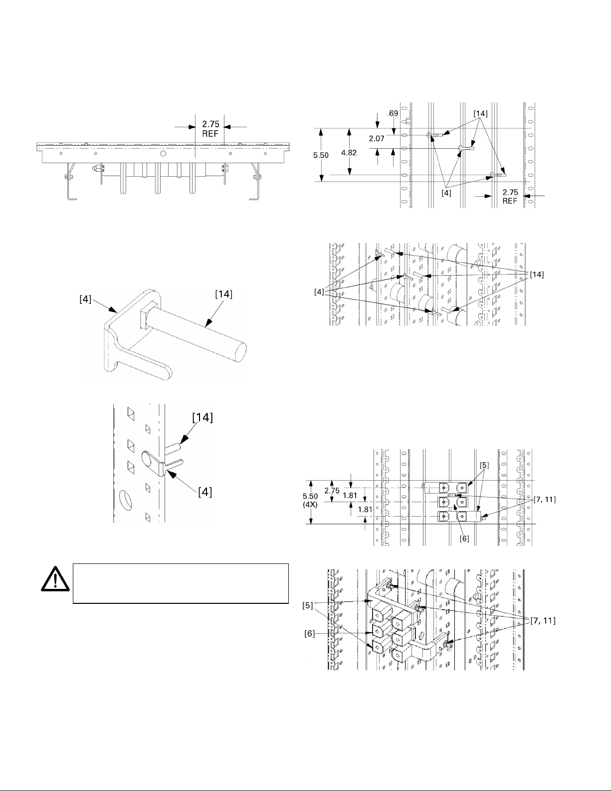
2. Locate the side of the interior with a 2.75-inch
p
reference distance. The circuit breaker straps are
mounted on the side of the panel interior bus at
which the distance from the vertical bus face to the
inner face of the bus-support rail is 2.75 inches, as
indicated in Figure 2.
4. Three-phase installations. Use the following procedure
for all three-phase installations (kit AMCB6GB).
4a. Install carriage bolt assemblies. Position the
carriage bolt [14] and antiturn clip [4] assemblies
as shown in Figures 5 and 6.
Edge of G
Frame
Edge of G
Frame
Figure 2. Illustration of the 2.75-inch reference distance.
3. Assemble antiturn clips onto carriage bolts. Slide an
antiturn clip [4] over the square shank of each
carriage bolt [14], as shown in Figure 3. Figure 4
illustrates the installation of a bolt and antiturn clip
onto the interior, as called for in the remaining steps.
Figure 3. Assembling an antiturn clip [4] with a carriage bolt [14].
Figure 5. Carriage bolt and antiturn clip installation for three-phase
connections.
Figure 6. Carriage bolt and antiturn clip installation for three-phase
connections, isometric view.
4b. Install straps. Place the G frame straps [5, 6] over
the carriage bolts and antiturn clips, as shown in
Figures 7 and 8. Place conical washers [7] on the
bolts and secure with nuts [11]. Leave the
connections finger tight.
If the group assembly selection is three-phase and
the assembly looks like Figure 8, then go to step 6.
Edge of G
Frame
Figure 4. Installing a carriage bolt [14] and antiturn clip [4] into the
interior.
NOTE: For three-phase installations, continue
with ste
4. For two-pole installations, proceed
to step 5.
Edge of G
Frame
Figure 7. Installing the straps for three-phase connections.
Figure 8. Installing the straps for three-phase connections, isometric
view.
Page 3

5. Two-pole installations. Use the following procedure
for all two-pole installations (kit AMCB4GB).
• For installations using phases A and B, continue
with step 5a.
• For installations using phases A and C, proceed to
step 5c.
• For installations using phases B and C, proceed to
step 5e.
5a. Install carriage bolt assemblies on phases A and B.
Position the carriage bolt [14] and antiturn clip
[4] assemblies as shown in Figures 9 and 10.
Edge of G
Frame
Edge of G
Frame
Figure 12. Installing straps on phases A and B, isometric view.
5c. Install carriage bolt assemblies on phases A and C.
Position the carriage bolt [14] and antiturn clip
[4] assemblies as shown in Figures 13 and 14.
Edge of G
Frame
Figure 9. Installing carriage bolt assemblies on phases A and B.
Figure 10. Installing carriage bolt assemblies on phases A and B,
isometric view.
5b. Install straps on phases A and B. Place the G
frame straps [5, 6] over the carriage bolts and
antiturn clips, as shown in Figures 11 and 12.
Place conical washers [7] on the bolts and secure
with nuts [11]. Leave the connections finger tight.
If the group assembly selection is two-pole and the
assembly looks like Figure 12, then go to step 6.
Edge of G
Frame
Edge of G
Frame
Figure 13. Installing carriage bolt assemblies on phases A and C.
Figure 14. Installing carriage bolt assemblies on phases A and C,
isometric view.
5d. Install straps on phases A and C. Place the G
frame straps [5] over the carriage bolts and
antiturn clips, as shown in Figures 15 and 16.
Place conical washers [7] on the bolts and secure
with nuts [11]. Leave the connections finger tight.
If the group assembly selection is two-pole and the
assembly looks like Figure 16, then go to step 6.
Edge of G
Frame
Edge of G
Frame
Figure 11. Installing straps on phases A and B.
Edge of G
Frame
Figure 15. Installing straps on phases A and C.
Page 4

Figure 16. Installing straps on phases A and C, isometric view.
5e. Install carriage bolt assemblies on phases B and C.
Position the carriage bolt [14] and antiturn clip
[4] assemblies as shown in Figures 17 and 18.
Edge of G
Frame
Edge of G
Frame
Figure 17. Installing carriage bolt assemblies on phases B and C.
Figure 18. Installing carriage bolt assemblies on phases B and C,
isometric view.
5f. Install straps on phases B and C. Place the G
frame straps [5, 6] over the carriage bolts and
antiturn clips, as shown in Figures 19 and 20.
Place conical washers [7] on the bolts and secure
with nuts [11]. Leave the connections finger tight.
If the group assembly selection is two-pole and the
assembly looks like Figure 20, then go to step 6.
Figure 20. Installing straps on phases B and C, isometric view.
6. Install the breaker mounting brackets. Secure the
breaker mounting brackets [3] to the panel side rail
with thread-forming screws [1], as shown in Figure 21.
Tighten the screws to 30 in-lb.
Figure 21. Installing the breaker mounting brackets [3].
7. Install the circuit breakers. Position the breakers so
that the line- or
ON-side terminals rest on the
underlying strap contact blocks and the opposite sides
are supported by the mounting brackets [3], as shown
in Figure 22. Align the holes in each breaker housing
with the corresponding holes in the mounting
brackets. Secure the breakers to the brackets with the
machine screws [12] and flat washers [13] and tighten
to 18 in-lb. Attach the line-side breaker terminals to
the threaded holes in the strap contact blocks with
conical spring washers [8] and hex-head bolts [10].
Tighten each connection to 75 in-lb.
NOTE: Straps may require minor adjustments
for proper hole alignment.
Edge of G
Frame
Edge of G
Frame
Figure 19. Installing straps on phases B and C.
Figure 22. Installing the circuit breakers on the mounting brackets
and strap blocks.
Page 5

8. Install the terminal cover. Install the terminal cover
over the center of the assembly, as shown in Figure 23.
Secure the cover with thread-cutting screws [15].
Figure 23. Installing the terminal cover over the breaker terminals.
9. Tighten the strap connections. Tighten the bolted
strap connections to the vertical bus to 65 in-lb. It may
be necessary to remove an adjacent breaker to allow
access to the bolted connections at the vertical bus.
10. Insulate unused strap surfaces. The double-branch
assembly may be installed with only one active circuit
breaker and the other branch left open for future use.
In this case, insulate the exposed surfaces of the strap
contact blocks in the unused branch. Cover the
contact surfaces with two layers of a UL-recognized
105° C thermoplastic tape (OANZ2, such as Permacel
P-30-105 or 3M 66R) to achieve a minimum insulation
thickness of 0.013 inch.
Page 6

g
These instructions do not cover all details or variations in e
quip
y
p
ma
be met in connection with installation, operation, or maintenance. Should further information be desired or should
articular problems arise that are not covered sufficiently for the purchaser’s purposes, the matter should be referred to the
GE Company.
ment nor do they provide for every possible contingency that
GE Industrial Systems
General Electric Company
41 Woodford Ave., Plainville, CT 06062
DEH40129 R03 0901 © 2001 General Electric Company
 Loading...