

Page 1

PRELIMINARY
(AUGUST 23, 2012)
VE6_VE8_COVER.FM
GE Healthcare
Voluson E8 / Voluson E8 Expert
Voluson E6
Service Manual
• Voluson E6 / Voluson E8 / Voluson E8 Expert systems with Software version 9.x.x (BT09)
• Voluson E6 / Voluson E8 / Voluson E8 Expert systems with Software version 10.x.x (BT10)
• Voluson E6 / Voluson E8 / Voluson E8 Expert systems with Software version 12.x.x (BT12)
• Voluson E6 / Voluson E8 / Voluson E8 Expert systems with Software version EC200, 13.x.x (BT13 )
Document Number: KTD102576
Part Number: KTI301334
Revision: 7
0123
Page 2

Page 3

GE HEALTHCARE VOLUSON E8 / VOLUSON E6
WARNING
(EN)
AVERTISSEMENT
(FR)
WARNUNG
(DE)
D
IRECTION KTD102576, REVISION 7 SERVICE MANUAL
Important Precautions
TRANSLATION POLICY
THIS SERVICE MANUAL IS AVAILABLE IN ENGLISH ONLY.
• IF A CUSTOMER’S SERVICE PROVIDER REQUIRES A LANGUAGE OTHER
THAN ENGLISH, IT IS THE CUSTOMER’S RESPONSIBILITY TO PROVIDE
TRANSLATION SERVICES.
• DO NOT ATTEMPT TO SERVICE THE EQUIPMENT UNLESS THIS SERVICE
MANUAL HAS BEEN CONSULTED AND IS UNDERSTOOD.
• FAILURE TO HEED THIS WARNING MAY RESULT IN INJURY TO THE SERVICE
PROVIDER, OPERATOR OR PATIENT FROM ELECTRIC SHOCK, MECHANICAL
OR OTHER HAZARDS.
CE MANUEL DE MAINTENANCE N’EST DISPONIBLE QU’EN ANGLAIS.
• SI LE TECHNICIEN DU CLIENT A BESOIN DE CE MANUEL DANS UNE AUTRE
LANGUE QUE L’ANGLAIS, C’EST AU CLIENT QU’IL INCOMBE DE LE FAIRE
TRADUIRE.
• NE PAS TENTER D’INTERVENTION SUR LES ÉQUIPEMENTS TANT QUE LE
MANUEL SERVICE N’A PAS ÉTÉ CONSULTÉ ET COMPRIS.
• LE NON-RESPECT DE CET AVERTISSEMENT PEUT ENTRAÎNER CHEZ LE
TECHNICIEN, L’OPÉRATEUR OU LE PATIENT DES BLESSURES DUES À DES
DANGERS ÉLECTRIQUES, MÉCANIQUES OU AUTRES.
DIESES KUNDENDIENST-HANDBUCH EXISTIERT NUR IN ENGLISCHER
SPRACHE.
• FALLS EIN FREMDER KUNDENDIENST EINE ANDERE SPRACHE BENÖTIGT,
IST ES AUFGABE DES KUNDEN FÜR EINE ENTSPRECHENDE ÜBERSETZUNG
ZU SORGEN.
• VERSUCHEN SIE NICHT, DAS GERÄT ZU REPARIEREN, BEVOR DIESES
KUNDENDIENST-HANDBUCH NICHT ZU RATE GEZOGEN UND VERSTANDEN
WURDE.
• WIRD DIESE WARNUNG NICHT BEACHTET, SO KANN ES ZU VERLETZUNGEN
DES KUNDENDIENSTTECHNIKERS, DES BEDIENERS ODER DES PATIENTEN
DURCH ELEKTRISCHE SCHLÄGE, MECHANISCHE ODER SONSTIGE
GEFAHREN KOMMEN.
- i
Page 4

GE HEALTHCARE VOLUSON E8 / VOLUSON E6
AVISO
(ES)
ATENÇÃO
(PT-Br)
(PT-pt)
AVISO
AVVERTENZA
(IT)
D
IRECTION KTD102576, REVISION 7 SERVICE MANUAL
ESTE MANUAL DE SERVICIO SÓLO EXISTE EN INGLÉS.
• SI ALGÚN PROVEEDOR DE SERVICIOS AJENO A GEHC SOLICITA UN IDIOMA
QUE NO SEA EL INGLÉS, ES RESPONSABILIDAD DEL CLIENTE OFRECER UN
SERVICIO DE TRADUCCIÓN.
• NO SE DEBERÁ DAR SERVICIO TÉCNICO AL EQUIPO, SIN HABER
CONSULTADO Y COMPRENDIDO ESTE MANUAL DE SERVICIO.
• LA NO OBSERVANCIA DEL PRESENTE AVISO PUEDE DAR LUGAR A QUE EL
PROVEEDOR DE SERVICIOS, EL OPERADOR O EL PACIENTE SUFRAN
LESIONES PROVOCADAS POR CAUSAS ELÉCTRICAS, MECÁNICAS O DE
OTRA NATURALEZA.
ESTE MANUAL DE ASSISTÊNCIA TÉCNICA SÓ SE ENCONTRA DISPONÍVEL EM
INGLÊS.
• SE QUALQUER OUTRO SERVIÇO DE ASSISTÊNCIA TÉCNICA, QUE NÃO A
GEHC, SOLICITAR ESTES MANUAIS NOUTRO IDIOMA, É DA
RESPONSABILIDADE DO CLIENTE FORNECER OS SERVIÇOS DE TRADUÇÃO.
• NÃO TENTE REPARAR O EQUIPAMENTO SEM TER CONSULTADO E
COMPREENDIDO ESTE MANUAL DE ASSISTÊNCIA TÉCNICA.
• O NÃO CUMPRIMENTO DESTE AVISO PODE POR EM PERIGO A SEGURANÇA
DO TÉCNICO, OPERADOR OU PACIENTE DEVIDO A‘ CHOQUES ELÉTRICOS,
MECÂNICOS OU OUTROS.
ESTE MANUAL DE ASSISTÊNCIA ESTÁ DISPONÍVEL APENAS EM INGLÊS.
• SE QUALQUER OUTRO SERVIÇO DE ASSISTÊNCIA TÉCNICA, QUE NÃO A
GEHC, SOLICITAR ESTES MANUAIS NOUTRO IDIOMA, É DA
RESPONSABILIDADE DO CLIENTE FORNECER OS SERVIÇOS DE TRADUÇÃO.
• NÃO TENTE EFECTUAR REPARAÇÕES NO EQUIPAMENTO SEM TER
CONSULTADO E COMPREENDIDO PREVIAMENTE ESTE MANUAL.
• A INOBSERVÂNCIA DESTE AVISO PODE RESULTAR EM FERIMENTOS NO
TÉCNICO DE ASSISTÊNCIA, OPERADOR OU PACIENTE EM CONSEQUÊNCIA
DE CHOQUE ELÉCTRICO, PERIGOS DE ORIGEM MECÂNICA, BEM COMO DE
OUTROS TIPOS.
IL PRESENTE MANUALE DI MANUTENZIONE È DISPONIBILE SOLTANTO IN
INGLESE.
• SE UN ADDETTO ALLA MANUTENZIONE ESTERNO ALLA GEHC RICHIEDE IL
MANUALE IN UNA LINGUA DIVERSA, IL CLIENTE È TENUTO A PROVVEDERE
DIRETTAMENTE ALLA TRADUZIONE.
• SI PROCEDA ALLA MANUTENZIONE DELL’APPARECCHIATURA SOLO DOPO
AVER CONSULTATO IL PRESENTE MANUALE ED AVERNE COMPRESO IL
CONTENUTO.
• NON TENERE CONTO DELLA PRESENTE AVVERTENZA POTREBBE FAR
COMPIERE OPERAZIONI DA CUI DERIVINO LESIONI ALL’ADDETTO ALLA
MANUTENZIONE, ALL’UTILIZZATORE ED AL PAZIENTE PER FOLGORAZIONE
ELETTRICA, PER URTI MECCANICI OD ALTRI RISCHI.
ii -
Page 5

GE HEALTHCARE VOLUSON E8 / VOLUSON E6
HOIATUS
(ET)
VAROITUS
(FI)
ΠΡΟΕΙΔΟΠΟΙΗΣΗ
(EL)
FIGYELMEZTETÉS
(HU)
D
IRECTION KTD102576, REVISION 7 SERVICE MANUAL
KÄESOLEV TEENINDUSJUHEND ON SAADAVAL AINULT INGLISE KEELES.
• KUI KLIENDITEENINDUSE OSUTAJA NÕUAB JUHENDIT INGLISE KEELEST
ERINEVAS KEELES, VASTUTAB KLIENT TÕLKETEENUSE OSUTAMISE EEST.
• ÄRGE ÜRITAGE SEADMEID TEENINDADA ENNE EELNEVALT KÄESOLEVA
TEENINDUSJUHENDIGA TUTVUMIST JA SELLEST ARU SAAMIST.
• KÄESOLEVA HOIATUSE EIRAMINE VÕIB PÕHJUSTADA TEENUSEOSUTAJA,
OPERAATORI VÕI PATSIENDI VIGASTAMIST ELEKTRILÖÖGI, MEHAANILISE
VÕI MUU OHU TAGAJÄRJEL.
TÄMÄ HUOLTO-OHJE ON SAATAVILLA VAIN ENGLANNIKSI.
• JOS ASIAKKAAN PALVELUNTARJOAJA VAATII MUUTA KUIN
ENGLANNINKIELISTÄ MATERIAALIA, TARVITTAVAN KÄÄNNÖKSEN
HANKKIMINEN ON ASIAKKAAN VASTUULLA.
• ÄLÄ YRITÄ KORJATA LAITTEISTOA ENNEN KUIN OLET VARMASTI LUKENUT
JA YMMÄRTÄNYT TÄMÄN HUOLTO-OHJEEN.
• MIKÄLI TÄTÄ VAROITUSTA EI NOUDATETA, SEURAUKSENA VOI OLLA
PALVELUNTARJOAJAN, LAITTEISTON KÄYTTÄJÄN TAI POTILAAN
VAHINGOITTUMINEN SÄHKÖISKUN, MEKAANISEN VIAN TAI MUUN
VAARATILANTEEN VUOKSI.
ΤΟ ΠΑΡΟΝ ΕΓΧΕΙΡΙΔΙΟ ΣΕΡΒΙΣ ΔΙΑΤΙΘΕΤΑΙ ΣΤΑ ΑΓΓΛΙΚΑ ΜΟΝΟ.
• ΕΑΝ ΤΟ ΑΤΟΜΟ ΠΑΡΟΧΗΣ ΣΕΡΒΙΣ ΕΝΟΣ ΠΕΛΑΤΗ ΑΠΑΙΤΕΙ ΤΟ ΠΑΡΟΝ
ΕΓΧΕΙΡΙΔΙΟ ΣΕ ΓΛΩΣΣΑ ΕΚΤΟΣ ΤΩΝ ΑΓΓΛΙΚΩΝ, ΑΠΟΤΕΛΕΙ ΕΥΘΥΝΗ ΤΟΥ
ΠΕΛΑΤΗ ΝΑ ΠΑΡΕΧΕΙ ΥΠΗΡΕΣΙΕΣ ΜΕΤΑΦΡΑΣΗΣ.
• ΜΗΝ ΕΠΙΧΕΙΡΗΣΕΤΕ ΤΗΝ ΕΚΤΕΛΕΣΗ ΕΡΓΑΣΙΩΝ ΣΕΡΒΙΣ ΣΤΟΝ ΕΞΟΠΛΙΣΜΟ
ΕΚΤΟΣ ΕΑΝ
ΕΧΕΤΕ ΣΥΜΒΟΥΛΕΥΤΕΙ ΚΑΙ ΕΧΕΤΕ ΚΑΤΑΝΟΗΣΕΙ ΤΟ ΠΑΡΟΝ
ΕΓΧΕΙΡΙΔΙΟ ΣΕΡΒΙΣ.
• ΕΑΝ ΔΕ ΛΑΒΕΤΕ ΥΠΟΨΗ ΤΗΝ ΠΡΟΕΙΔΟΠΟΙΗΣΗ ΑΥΤΗ, ΕΝΔΕΧΕΤΑΙ ΝΑ
ΠΡΟΚΛΗΘΕΙ ΤΡΑΥΜΑΤΙΣΜΟΣ ΣΤΟ ΑΤΟΜΟ ΠΑΡΟΧΗΣ ΣΕΡΒΙΣ, ΣΤΟ ΧΕΙΡΙΣΤΗ Ή
ΣΤΟΝ ΑΣΘΕΝΗ ΑΠΟ ΗΛΕΚΤΡΟΠΛΗΞΙΑ, ΜΗΧΑΝΙΚΟΥΣ Ή ΑΛΛΟΥΣ ΚΙΝΔΥΝΟΥΣ.
EZEN KARBANTARTÁSI KÉZIKÖNYV KIZÁRÓLAG ANGOL NYELVEN ÉRHETŐ EL.
• HA A VEVŐ SZOLGÁLTATÓJA ANGOLTÓL ELTÉRŐ NYELVRE TART IGÉNYT,
AKKOR A VEVŐ FELELŐSSÉGE A FORDÍTÁS ELKÉSZÍTTETÉSE.
• NE PRÓBÁLJA ELKEZDENI HASZNÁLNI A BERENDEZÉST, AMÍG A
KARBANTARTÁSI KÉZIKÖNYVBEN LEÍRTAKAT NEM ÉRTELMEZTÉK.
• EZEN FIGYELMEZTETÉS FIGYELMEN KÍVÜL HAGYÁSA A SZOLGÁLTATÓ,
MŰKÖDTETŐ VAGY A BETEG ÁRAMÜTÉS, MECHANIKAI VAGY EGYÉB
VESZÉLYHELYZET MIATTI SÉRÜLÉSÉT EREDMÉNYEZHETI.
- iii
Page 6

GE HEALTHCARE VOLUSON E8 / VOLUSON E6
VIÐVÖRUN
(IS)
VÝSTRAHA
(CS)
ADVARSEL
(DA)
WAARSCHUWING
(NL)
D
IRECTION KTD102576, REVISION 7 SERVICE MANUAL
ÞESSI ÞJÓNUSTUHANDBÓK ER EINGÖNGU FÁANLEG Á ENSKU.
• EF ÞJÓNUSTUAÐILI VIÐSKIPTAMANNS ÞARFNAST ANNARS TUNGUMÁLS EN
ENSKU, ER ÞAÐ Á ÁBYRGÐ VIÐSKIPTAMANNS AÐ ÚTVEGA ÞÝÐINGU.
• REYNIÐ EKKI AÐ ÞJÓNUSTA TÆKIÐ NEMA EFTIR AÐ HAFA SKOÐAÐ OG
SKILIÐ ÞESSA ÞJÓNUSTUHANDBÓK.
• EF EKKI ER FARIÐ AÐ ÞESSARI VIÐVÖRUN GETUR ÞAÐ VALDIÐ MEIÐSLUM
ÞJÓNUSTUVEITANDA, STJÓRNANDA EÐA SJÚKLINGS VEGNA RAFLOSTS,
VÉLRÆNNAR EÐA ANNARRAR HÆTTU.
TENTO SERVISNÍ NÁVOD EXISTUJE POUZE V ANGLICKÉM JAZYCE.
•VPŘÍPADĚ, ŽE POSKYTOVATEL SLUŽEB ZÁKAZNÍKŮM POTŘEBUJE NÁVOD
V JINÉM JAZYCE, JE ZAJIŠTĚNÍ PŘEKLADU DO ODPOVÍDAJÍCÍHO JAZYKA
ÚKOLEM ZÁKAZNÍKA.
• NEPROVÁDĚJTE ÚDRŽBU TOHOTO ZAŘÍZENÍ, ANIŽ BYSTE SI PŘEČETLI
TENTO SERVISNÍ NÁVOD A POCHOPILI JEHO OBSAH.
•VPŘÍPADĚ NEDODRŽOVÁNÍ TÉTO VÝSTRAHY MŮŽE DOJÍT ÚRAZU
ELEKTRICKÁM PROUDEM PRACOVNÍKA POSKYTOVATELE SLUŽEB,
OBSLUŽNÉHO PERSONÁLU NEBO PACIENTŮ VLIVEM ELEKTRICKÉHOP
PROUDU, RESPEKTIVE VLIVEM K RIZIKU MECHANICKÉHO POŠKOZENÍ NEBO
JINÉMU RIZIKU.
DENNE SERVICEMANUAL FINDES KUN PÅ ENGELSK.
• HVIS EN KUNDES TEKNIKER HAR BRUG FOR ET ANDET SPROG END
ENGELSK, ER DET KUNDENS ANSVAR AT SØRGE FOR OVERSÆTTELSE.
• FORSØG IKKE AT SERVICERE UDSTYRET MEDMINDRE
DENNE SERVICEMANUAL ER BLEVET LÆST OG FORSTÅET.
• MANGLENDE OVERHOLDELSE AF DENNE ADVARSEL KAN MEDFŘRE SKADE
PĹ GRUND AF ELEKTRISK, MEKANISK ELLER ANDEN FARE FOR
TEKNIKEREN, OPERATŘREN ELLER PATIENTEN.
DEZE ONDERHOUDSHANDLEIDING IS ENKEL IN HET ENGELS VERKRIJGBAAR.
• ALS HET ONDERHOUDSPERSONEEL EEN ANDERE TAAL VEREIST, DAN IS DE
KLANT VERANTWOORDELIJK VOOR DE VERTALING ERVAN.
• PROBEER DE APPARATUUR NIET TE ONDERHOUDEN VOORDAT DEZE
ONDERHOUDSHANDLEIDING WERD GERAADPLEEGD EN BEGREPEN IS.
• INDIEN DEZE WAARSCHUWING NIET WORDT OPGEVOLGD, ZOU HET
ONDERHOUDSPERSONEEL, DE OPERATOR OF EEN PATIËNT GEWOND
KUNNEN RAKEN ALS GEVOLG VAN EEN ELEKTRISCHE SCHOK,
MECHANISCHE OF ANDERE GEVAREN.
iv -
Page 7

GE HEALTHCARE VOLUSON E8 / VOLUSON E6
BRÎDINÂJUMS
(LV)
ĮSPĖJIMAS
(LT)
ADVARSEL
(NO)
OSTRZEŻENIE
(PL)
D
IRECTION KTD102576, REVISION 7 SERVICE MANUAL
ŠĪ APKALPES ROKASGRĀMATA IR PIEEJAMA TIKAI ANGĻU VALODĀ.
• JA KLIENTA APKALPES SNIEDZĒJAM NEPIECIEŠAMA INFORMĀCIJA CITĀ
VALODĀ, NEVIS ANGĻU, KLIENTA PIENĀKUMS IR NODROŠINĀT TULKOŠANU.
• NEVEICIET APRĪKOJUMA APKALPI BEZ APKALPES ROKASGRĀMATAS
IZLASĪŠANAS UN SAPRAŠANAS.
•ŠĪ BRĪDINĀJUMA NEIEVĒROŠANA VAR RADĪT ELEKTRISKĀS STRĀVAS
TRIECIENA, MEHĀNISKU VAI CITU RISKU IZRAISĪTU TRAUMU APKALPES
SNIEDZĒJAM, OPERATORAM VAI PACIENTAM.
ŠIS EKSPLOATAVIMO VADOVAS YRA IŠLEISTAS TIK ANGLŲ KALBA.
• JEI KLIENTO PASLAUGŲ TEIKĖJUI REIKIA VADOVO KITA KALBA – NE ANGLŲ,
VERTIMU PASIRŪPINTI TURI KLIENTAS.
•NEMĖGINKITE ATLIKTI ĮRANGOS TECHNINĖS PRIEŽIŪROS DARBŲ, NEBENT
VADOVAUTUMĖTĖS ŠIUO EKSPLOATAVIMO VADOVU IR JĮ SUPRASTUMĖTE
• NEPAISANT ŠIO PERSPĖJIMO, PASLAUGŲ TEIKĖJAS, OPERATORIUS AR
PACIENTAS GALI BŪTI SUŽEISTAS DĖL ELEKTROS SM
ŪGIO, MECHANINIŲ AR
KITŲ PAVOJŲ.
DENNE SERVICEHÅNDBOKEN FINNES BARE PÅ ENGELSK.
• HVIS KUNDENS SERVICELEVERANDØR TRENGER ET ANNET SPRÅK, ER DET
KUNDENS ANSVAR Å SØRGE FOR OVERSETTELSE.
• IKKE FORSØK Å REPARERE UTSTYRET UTEN AT DENNE
SERVICEHÅNDBOKEN ER LEST OG FORSTÅTT.
• MANGLENDE HENSYN TIL DENNE ADVARSELEN KAN FØRE TIL AT
SERVICELEVERANDØREN, OPERATØREN ELLER PASIENTEN SKADES PÅ
GRUNN AV ELEKTRISK STØT, MEKANISKE ELLER ANDRE FARER.
NINIEJSZY PODRĘCZNIK SERWISOWY DOSTĘPNY JEST JEDYNIE W JĘZYKU
ANGIELSKIM.
•JEŚLI FIRMA ŚWIADCZĄCA KLIENTOWI USłUGI SERWISOWE WYMAGA
UDOSTĘPNIENIA PODRĘCZNIKA W JĘZYKU INNYM NIŻ ANGIELSKI,
OBOWIĄZEK ZAPEWNIENIA STOSOWNEGO TłUMACZENIA SPOCZYWA NA
KLIENCIE.
• NIE PRÓBOWAĆ SERWISOWAĆ NINIEJSZEGO SPRZĘTU BEZ UPRZEDNIEGO
ZAPOZNANIA SIĘ Z PODRĘCZNIKIEM SERWISOWYM.
• NIEZASTOSOWANIE SIĘ DO TEGO OSTRZEŻENIA MOżE GROZIĆ
OBRAŻENIAMI CIAłA SERWISANTA, OPERATORA LUB PACJENTA W WYNIKU
PORAŻENIA PRĄDEM, URAZU MECHANICZNEGO LUB INNEGO RODZAJU
ZAGROŻEŃ.
- v
Page 8

GE HEALTHCARE VOLUSON E8 / VOLUSON E6
ATENŢIE
(RO)
ОСТОРОЖНО!
(RU)
(BG)
ПРЕДУПРЕЖДЕНИЕ
UPOZORENJE
(SR)
D
IRECTION KTD102576, REVISION 7 SERVICE MANUAL
ACEST MANUAL DE SERVICE ESTE DISPONIBIL NUMAI ÎN LIMBA ENGLEZĂ.
• DACĂ UN FURNIZOR DE SERVICII PENTRU CLIENŢI NECESITĂ O ALTĂ LIMBĂ
DECÂT CEA ENGLEZĂ, ESTE DE DATORIA CLIENTULUI SĂ FURNIZEZE O
TRADUCERE.
• NU ÎNCERCAŢI SĂ REPARAŢI ECHIPAMENTUL DECÂT ULTERIOR
CONSULTĂRII ŞI ÎNŢELEGERII ACESTUI MANUAL DE SERVICE.
• IGNORAREA ACESTUI AVERTISMENT AR PUTEA DUCE LA RĂNIREA
DEPANATORULUI, OPERATORULUI SAU PACIENTULUI ÎN URMA
PERICOLELOR DE ELECTROCUTARE, MECANICE SAU DE ALTĂ NATURĂ.
ДАННОЕ РУКОВОДСТВО ПО ОБСЛУЖИВАНИЮ ПРЕДОСТАВЛЯЕТСЯ ТОЛЬКО
НА АНГЛИЙСКОМ ЯЗЫКЕ.
• ЕСЛИ СЕРВИСНОМУ ПЕРСОНАЛУ КЛИЕНТА НЕОБХОДИМО РУКОВОДСТВО
НЕ НА АНГЛИЙСКОМ ЯЗЫКЕ, КЛИЕНТУ СЛЕДУЕТ САМОСТОЯТЕЛЬНО
ОБЕСПЕЧИТЬ ПЕРЕВОД.
• ПЕРЕД ОБСЛУЖИВАНИЕМ ОБОРУДОВАНИЯ ОБЯЗАТЕЛЬНО
ОБРАТИТЕСЬ
К ДАННОМУ РУКОВОДСТВУ И ПОЙМИТЕ ИЗЛОЖЕННЫЕ В НЕМ СВЕДЕНИЯ.
• НЕСОБЛЮДЕНИЕ УКАЗАННЫХ ТРЕБОВАНИЙ МОЖЕТ ПРИВЕСТИ К ТОМУ,
ЧТО СПЕЦИАЛИСТ ПО ТЕХОБСЛУЖИВАНИЮ, ОПЕРАТОР ИЛИ ПАЦИЕНТ
ПОЛУЧАТ УДАР ЗЛЕКТРИЧЕСКИМ ТОКОМ, МЕХАНИЧЕСКУЮ ТРАВМУ ИЛИ
ДРУГОЕ ПОВРЕЖДЕНИЕ.
ТОВА СЕРВИЗНО РЪКОВОДСТВО Е НАЛИЧНО САМО НА АНГЛИЙСКИ ЕЗИК.
• АКО ДОСТАВЧИКЪТ НА СЕРВИЗНИ УСЛУГИ НА КЛИЕНТ
СЕ НУЖДАЕ ОТ
ЕЗИК, РАЗЛИЧЕН ОТ АНГЛИЙСКИ, ЗАДЪЛЖЕНИЕ НА КЛИЕНТА Е ДА
ПРЕДОСТАВИ ПРЕВОДАЧЕСКА УСЛУГА.
• НЕ СЕ ОПИТВАЙТЕ ДА ИЗВЪРШВАТЕ СЕРВИЗНО ОБСЛУЖВАНЕ НА ТОВА
ОБОРУДВАНЕ, ОСВЕН ВСЛУЧАЙ, ЧЕ СЕРВИЗНОТО РЪКОВОДСТВО Е
ПРОЧЕТЕНО И СЕ РАЗБИРА.
• НЕСПАЗВАНЕТО НА ТОВА ПРЕДУПРЕЖДЕНИЕ МОЖЕ ДА ДОВЕДЕ ДО
НАРАНЯВАНЕ НА ДОСТАВЧИКА НА СЕРВИЗНИ УСЛУГИ, НА
ОПЕРАТОРА
ИЛИ ПАЦИЕНТА ВСЛЕДСТВИЕНА ТОКОВ УДАР, МЕХАНИЧНИ ИЛИ ДРУГИ
РИСКОВЕ.
OVAJ PRIRUČNIK ZA SERVISIRANJE DOSTUPAN JE SAMO NA ENGLESKOM
JEZIKU.
• AKO KLIJENTOV SERVISER ZAHTEVA JEZIK KOJI NIJE ENGLESKI,
ODGOVORNOST JE NA KLIJENTU DA PRUŽI USLUGE PREVOĐENJA.
• NEMOJTE POKUŠAVATI DA SERVISIRATE OPREMU AKO NISTE PROČITALI I
RAZUMELI PRIRUČNIK ZA SERVISIRANJE.
• AKO NE POŠTUJETE OVO UPOZORENJE, MOŽE DOĆI DO POVREĐIVANJA
SERVISERA, OPERATERA ILI PACIJENTA UZROKOVANOG ELEKTRIČNIM
UDAROM, MEHANIČKIM I DRUGIM OPASNOSTIMA.
vi -
Page 9

GE HEALTHCARE VOLUSON E8 / VOLUSON E6
OPOZORILO
(SL)
UPOZORENJE
(HR)
UPOZORNENIE
(SK)
VARNING
(SV)
D
IRECTION KTD102576, REVISION 7 SERVICE MANUAL
TA SERVISNI PRIROČNIK JE NA VOLJO SAMO V ANGLEŠČINI.
• ČE PONUDNIK SERVISNIH STORITEV ZA STRANKO POTREBUJE NAVODILA V
DRUGEM JEZIKU, JE ZA PREVOD ODGOVORNA STRANKA SAMA.
• NE POSKUŠAJTE SERVISIRATI OPREME, NE DA BI PREJ PREBRALI IN
RAZUMELI SERVISNI PRIROČNIK.
• ČE TEGA OPOZORILA NE UPOŠTEVATE, OBSTAJA NEVARNOST
ELEKTRIČNEGA UDARA, MEHANSKIH ALI DRUGIH NEVARNOSTI IN
POSLEDIČNIH POŠKODB PONUDNIKA SERVISNIH STORITEV, UPORABNIKA
OPREME ALI PACIENTA.
OVAJ SERVISNI PRIRUČNIK DOSTUPAN JE SAMO NA ENGLESKOM JEZIKU.
• AKO KLIJENTOV SERVISER ZAHTIJEVA JEZIK KOJI NIJE ENGLESKI,
ODGOVORNOST KLIJENTA JE PRUŽITI USLUGE PREVOĐENJA.
• NEMOJTE POKUŠAVATI SERVISIRATI OPREMU AKO NISTE PROČITALI I
RAZUMJELI SERVISNI PRIRUČNIK.
• AKO NE POŠTUJETE OVO UPOZORENJE, MOŽE DOĆI DO OZLJEDE
SERVISERA, OPERATERA ILI PACIJENTA PROUZROČENE STRUJNIM
UDAROM, MEHANIČKIM I DRUGIM OPASNOSTIMA.
TÁTO SERVISNÁ PRÍRUČKA JE K DISPOZÍCII LEN V ANGLIČTINE.
• AK ZÁKAZNÍKOV POSKYTOVATEĽ SLUŽIEB VYŽADUJE INÝ JAZYK AKO
ANGLIČTINU, POSKYTNUTIE PREKLADATEĽSKÝCH SLUŽIEB JE
ZODPOVEDNOSŤOU ZÁKAZNÍKA.
• NEPOKÚŠAJTE SA VYKONÁVAŤ SERVIS ZARIADENIA SKÔR, AKO SI
NEPREČÍTATE SERVISNÚ PRÍRUČKU A NEPOROZUMIETE JEJ.
• ZANEDBANIE TOHTO UPOZORNENIA MÔŽE VYÚSTIŤ DO ZRANENIA
POSKYTOVATEĽA SLUŽIEB, OBSLUHUJÚCEJ OSOBY ALEBO PACIENTA
ELEKTRICKÝM PRÚDOM, PRÍPADNE DO MECHANICKÉHO ALEBO INÉHO
NEBEZPEČENSTVA.
DEN HÄR SERVICEHANDBOKEN FINNS BARA TILLGÄNGLIG PÅ ENGELSKA.
• OM EN KUNDS SERVICETEKNIKER HAR BEHOV AV ETT ANNAT SPRÅK ÄN
ENGELSKA ANSVARAR KUNDEN FÖR ATT TILLHANDAHÅLLA
ÖVERSÄTTNINGSTJÄNSTER.
• FÖRSÖK INTE UTFÖRA SERVICE PÅ UTRUSTNINGEN OM DU INTE HAR LÄST
OCH FÖRSTÅR DEN HÄR SERVICEHANDBOKEN.
• OM DU INTE TAR HÄNSYN TILL DEN HÄR VARNINGEN KAN DET RESULTERA I
SKADOR PÅ SERVICETEKNIKERN, OPERATÖREN ELLER PATIENTEN TILL
FÖLJD AV ELEKTRISKA STÖTAR, MEKANISKA FAROR ELLER ANDRA FAROR.
- vii
Page 10
GE HEALTHCARE VOLUSON E8 / VOLUSON E6
DİKKAT
(TR)
(JA)
Traditional
Chinese
D
IRECTION KTD102576, REVISION 7 SERVICE MANUAL
BU SERVİS KILAVUZU YALNIZCA İNGİLİZCE OLARAK SAĞLANMIŞTIR.
•EĞER MÜŞTERİ TEKNİSYENİ KILAVUZUN İNGİLİZCE DIŞINDAKİ BİR DİLDE
OLMASINI İSTERSE, KILAVUZU TERCÜME ETTİRMEK MÜŞTERİNİN
SORUMLULUĞUNDADIR.
•SERVİS KILAVUZUNU OKUYUP ANLAMADAN EKİPMANLARA MÜDAHALE
ETMEYİNİZ.
• BU UYARININ GÖZ ARDI EDİLMESİ, ELEKTRİK ÇARLPMASI YA DA MEKANİK
VEYA DİĞER TÜRDEN KAZALAR SONUCUNDA TEKNİSYENİN, OPERATÖRÜN
YA DA HASTANIN YARALANMASINA YOL AÇABİLİR.
viii -
Page 11
GE HEALTHCARE VOLUSON E8 / VOLUSON E6
(ZH-CN)
(KO)
D
IRECTION KTD102576, REVISION 7 SERVICE MANUAL
- ix
Page 12

GE HEALTHCARE VOLUSON E8 / VOLUSON E6
DANGER
WARNINGWARNING
D
IRECTION KTD102576, REVISION 7 SERVICE MANUAL
DAMAGE IN TRANSPORTATION - FOR USA ONLY
All packages should be closely examined at time of delivery. If damage is apparent write “Damage In
Shipment” on ALL copies of the freight or express bill BEFORE delivery is accepted or “signed for” by
a GE representative or hospital receiving agent. Whether noted or concealed, damage MUST be
reported to the carrier immediately upon discovery, or in any event, within 14 days after receipt, and the
contents and containers held for inspection by the carrier. A transportation company will not pay a claim
for damage if an inspection is not requested within this 14 day period.
CERTIFIED ELECTRICAL CONTRACTOR STATEMENT - FOR USA ONLY
All electrical Installations that are preliminary to position ing of the equipment at the site prepared for the
equipment shall be performed by licensed electrical contractors. Othe r conn ections between pieces o f
electrical equipment, calibrations and testing sha ll be performed by q ualified GE Healthcare person nel.
In performing all electrical work on these products, GE will use its own specially trained field engineers.
All of GE’s electrical work on these products will comply with the requirements of the applicable
electrical codes.
The purchaser of GE equipment shall only utilize qualified personnel (i.e., GE’s field engineers,
personnel of third-party service companies with equivalent training, or licensed electricians) to perform
electrical servicing on the equipment.
OMISSIONS & ERRORS
If there are any omissions, errors or suggestions for improving this documentation, please contact the
GE Healthcare Service Documentation Group with specific information listing the system type, manual
title, part number, revision number, page number and suggestion details.
Mail the information to:
GE Healthcare Austria GmbH & Co. OG
Tiefenbach 15
A-4871 Zipf
Austria - Europe
Attn.: “Service Documentation”
SERVICE SAFETY CONSIDERATIONS
DANGEROUS VOLTAGES, CAPABLE OF CAUSING DEATH, ARE PRESENT IN
!! DANGER:
THIS EQUIPMENT. USE EXTREME CAUTION WHEN HANDLING, TESTING AND
ADJUSTING.
Use all Personal Protection Equipment (PPE) such as gloves, safety shoes, safety
!! WARNING:
glasses, and kneeling pad, to reduce the risk of injury.
x -
Page 13

GE HEALTHCARE VOLUSON E8 / VOLUSON E6
D
IRECTION KTD102576, REVISION 7 SERVICE MANUAL
LEGAL NOTES
The contents of this publication may not be copied or duplicated in any form, in whole or in part, without
prior written permission of GE Healthcare.
GE Healthcare may revise this publication from time to time without written notice.
TRADEMARKS
All products and their name brands are trademarks of their respective holders.
COPYRIGHTS
All Material Copyright© 2009 - 2012 by General Electric Inc. All Rights Reserved.
- xi
Page 14
GE HEALTHCARE VOLUSON E8 / VOLUSON E6
D
IRECTION KTD102576, REVISION 7 SERVICE MANUAL
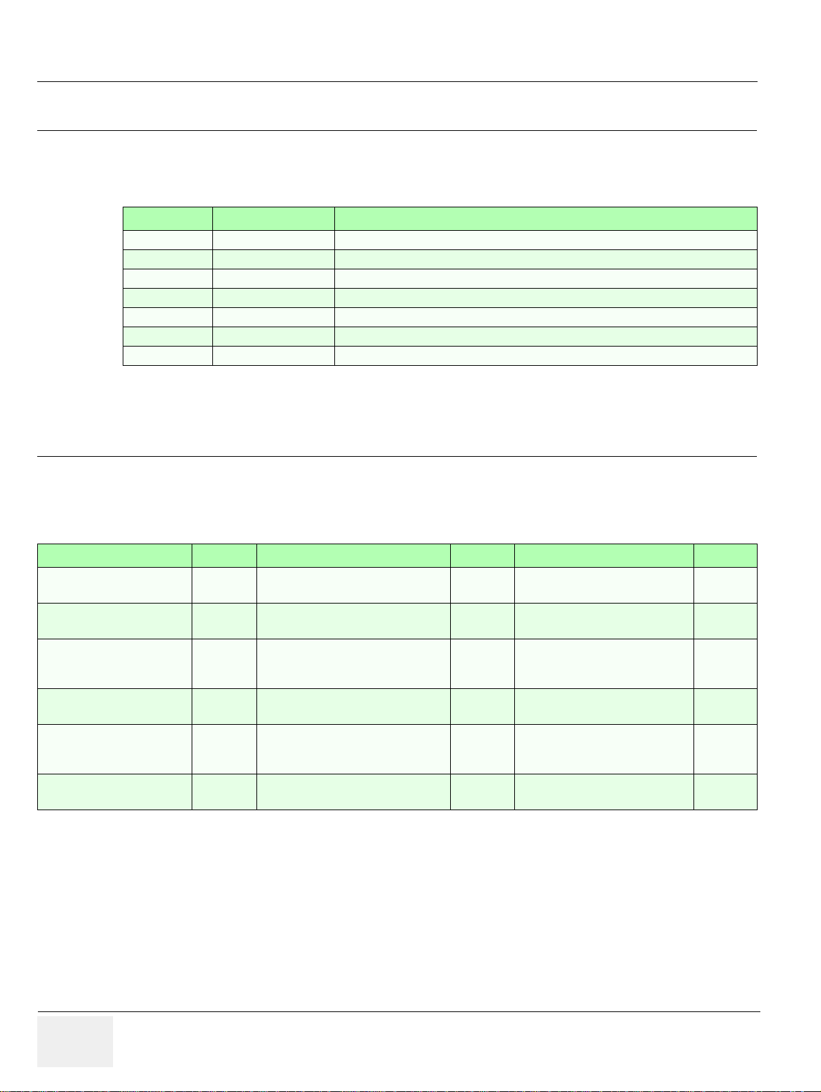
Revision History
Revision Date Reason for change
1 March 2009 Initial Release
2 June 2009 Implementation of Appendix A (Acoustic Output & Index Determination Tables)
3 September 2009 new Software version, general update
4 April 2010 Breakthrough BT10 (SW 10.x.x), new parts
5 March 2011 new parts, general update, company name
6 September 2011 Breakthrough BT12
7 August 2012 Breakthrough BT13 (EC200, 13.x.x), general update, new parts
List of Effected Pages
Pages Revision Pages Revision Pages Revision
Title Page
Important Precautions
pages i to xi
Rev History/LOEP
page xii
Table of Contents
pages xiii to xxxvi
Chapter 1 - Introduction
pages 1-1 to 1-18
Chapter 2 - Site Preparation
pages 2-1 to 2-10
Chapter 3 - Setup Instructions
7
pages 3-1 to 3-70
Chapter 4 - Functional Checks
7
pages 4-1 to 4-48
Chapter 5 - Components and
Functions (Theory)
7
pages 5-1 to 5-78
Chapter 6 - Service Adjustments
7
pages 6-1 to 6-10
Chapter 7 - Diagnostics/
Troubleshooting
7
pages 7-1 to 7-46
Chapter 8 - Replacement Procedures
7
pages 8-1 to 8-34
Chapter 9 - Renewal Parts
7
pages 9-1 to 9-48
Chapter 10 - Care & Maintenance
7
pages 10-1 to 10-26
Index
pages I to IV
7
Back Cover
7
7
7
7
7
7
7
xii -
Page 15

GGE HEALTHCARE VOLUSON E8 / VOLUSON E6
D
IRECTION KTD102576, REVISION 7 SERVICE MANUAL
Table of Contents
CHAPTER 1
Introduction
Overview . . . . . . . . . . . . . . . . . . . . . . . . . . . . . . . . . . . . . . . . . . . . . . . . . . . . . . . . . 1 - 1
Purpose of this Chapter . . . . . . . . . . . . . . . . . . . . . . . . . . . . . . . . . . . . . . . . 1 - 1
Contents in this Chapter . . . . . . . . . . . . . . . . . . . . . . . . . . . . . . . . . . . . . . . . 1 - 1
Purpose of Service Manual . . . . . . . . . . . . . . . . . . . . . . . . . . . . . . . . . . . . . 1 - 1
Typical Users of the Basic Service Manual . . . . . . . . . . . . . . . . . . . . . . . . . 1 - 2
Models Covered by this Manual . . . . . . . . . . . . . . . . . . . . . . . . . . . . . . . . . 1 - 2
System History - Hardware and Software Versions . . . . . . . . . . . . . . . . . . . 1 - 5
How to identify the Systems . . . . . . . . . . . . . . . . . . . . . . . . . . . . . . . 1 - 6
Purpose of Operator Manual(s) . . . . . . . . . . . . . . . . . . . . . . . . . . . . . . . . . . 1 - 6
Important Conventions. . . . . . . . . . . . . . . . . . . . . . . . . . . . . . . . . . . . . . . . . . . . . . . 1 - 7
Conventions Used in this Manual . . . . . . . . . . . . . . . . . . . . . . . . . . . . . . . . . 1 - 7
Standard Hazard Icons . . . . . . . . . . . . . . . . . . . . . . . . . . . . . . . . . . . . . . . . 1 - 8
Product Labels and Icons . . . . . . . . . . . . . . . . . . . . . . . . . . . . . . . . . . . . . . . 1 - 8
Safety Considerations . . . . . . . . . . . . . . . . . . . . . . . . . . . . . . . . . . . . . . . . . . . . . . . 1 - 11
Introduction . . . . . . . . . . . . . . . . . . . . . . . . . . . . . . . . . . . . . . . . . . . . . . . . . 1 - 11
Human Safety . . . . . . . . . . . . . . . . . . . . . . . . . . . . . . . . . . . . . . . . . . . . . . . 1 - 11
Mechanical Safety . . . . . . . . . . . . . . . . . . . . . . . . . . . . . . . . . . . . . . . . . 1 - 11
Electrical Safety . . . . . . . . . . . . . . . . . . . . . . . . . . . . . . . . . . . . . . . . . . . . . . 1 - 12
Safe Practices . . . . . . . . . . . . . . . . . . . . . . . . . . . . . . . . . . . . . . . . . . 1 - 12
Probes . . . . . . . . . . . . . . . . . . . . . . . . . . . . . . . . . . . . . . . . . . . . . . . . 1 - 12
Auxiliary Devices Safety . . . . . . . . . . . . . . . . . . . . . . . . . . . . . . . . . . . . . . . 1 - 12
Labels Locations . . . . . . . . . . . . . . . . . . . . . . . . . . . . . . . . . . . . . . . . . . . . . 1 - 14
Identification and Rating Plate . . . . . . . . . . . . . . . . . . . . . . . . . . . . . . 1 - 14
Dangerous Procedure Warnings . . . . . . . . . . . . . . . . . . . . . . . . . . . . . . . . . 1 - 15
Lockout/Tagout Requirements (For USA Only) . . . . . . . . . . . . . . . . . . . . . . 1 - 15
Returning/Shipping System, Probes and Repair Parts . . . . . . . . . . . . . . . . 1 - 15
Electromagnetic Compatibility (EMC) . . . . . . . . . . . . . . . . . . . . . . . . . . . . . . . . . . . 1 - 16
What is EMC? . . . . . . . . . . . . . . . . . . . . . . . . . . . . . . . . . . . . . . . . . . . . . . . 1 - 16
Compliance . . . . . . . . . . . . . . . . . . . . . . . . . . . . . . . . . . . . . . . . . . . . . . . . . 1 - 16
Electrostatic Discharge (ESD) Prevention . . . . . . . . . . . . . . . . . . . . . . . . . 1 - 16
Customer Assistance. . . . . . . . . . . . . . . . . . . . . . . . . . . . . . . . . . . . . . . . . . . . . . . . 1 - 17
Contact Information . . . . . . . . . . . . . . . . . . . . . . . . . . . . . . . . . . . . . . . . . . . 1 - 17
xiii Table of Contents
Page 16

GE HEALTHCARE VOLUSON E8 / VOLUSON E6
D
IRECTION KTD102576, REVISION 7 SERVICE MANUAL
System Manufacturer . . . . . . . . . . . . . . . . . . . . . . . . . . . . . . . . . . . . . . . . . 1 - 17
xiv Table of Contents
Page 17

GE HEALTHCARE VOLUSON E8 / VOLUSON E6
D
IRECTION KTD102576, REVISION 7 SERVICE MANUAL
CHAPTER 2
Site Preparation
Overview. . . . . . . . . . . . . . . . . . . . . . . . . . . . . . . . . . . . . . . . . . . . . . . . . . . . . . . . . 2 - 1
Purpose of this Chapter . . . . . . . . . . . . . . . . . . . . . . . . . . . . . . . . . . . . . . . 2 - 1
Contents in this Chapter . . . . . . . . . . . . . . . . . . . . . . . . . . . . . . . . . . . . . . . 2 - 1
General Console Requirements. . . . . . . . . . . . . . . . . . . . . . . . . . . . . . . . . . . . . . . 2 - 2
Environmental Requirements . . . . . . . . . . . . . . . . . . . . . . . . . . . . . . . . . . 2 - 2
Cooling . . . . . . . . . . . . . . . . . . . . . . . . . . . . . . . . . . . . . . . . . . . . . . . 2 - 2
Lighting . . . . . . . . . . . . . . . . . . . . . . . . . . . . . . . . . . . . . . . . . . . . . . 2 - 2
Electrical Requirements . . . . . . . . . . . . . . . . . . . . . . . . . . . . . . . . . . . . . . . 2 - 2
Voluson E8 / Voluson E6 Power Requirements . . . . . . . . . . . . . . . . 2 - 3
Inrush Current . . . . . . . . . . . . . . . . . . . . . . . . . . . . . . . . . . . . . . . . . 2 - 3
Site Circuit Breaker . . . . . . . . . . . . . . . . . . . . . . . . . . . . . . . . . . . . . 2 - 3
Site Power Outlets . . . . . . . . . . . . . . . . . . . . . . . . . . . . . . . . . . . . . . 2 - 3
Main Power Plug . . . . . . . . . . . . . . . . . . . . . . . . . . . . . . . . . . . . . . . 2 - 3
EMI Limitations . . . . . . . . . . . . . . . . . . . . . . . . . . . . . . . . . . . . . . . . . . . . . . 2 - 4
Probe Environmental Requirements . . . . . . . . . . . . . . . . . . . . . . . . . . . . . . 2 - 5
Time and Manpower Requirements . . . . . . . . . . . . . . . . . . . . . . . . . . . . . . 2 - 5
System Specifications . . . . . . . . . . . . . . . . . . . . . . . . . . . . . . . . . . . . . . . . . 2 - 5
Physical Dimensions of Voluson E8 / Voluson E6 . . . . . . . . . . . . . . 2 - 5
Acoustic Noise Output . . . . . . . . . . . . . . . . . . . . . . . . . . . . . . . . . . . 2 - 5
Electrical Specifications . . . . . . . . . . . . . . . . . . . . . . . . . . . . . . . . . . 2 - 5
Facility Needs. . . . . . . . . . . . . . . . . . . . . . . . . . . . . . . . . . . . . . . . . . . . . . . . . . . . . 2 - 6
Purchaser Responsibilities . . . . . . . . . . . . . . . . . . . . . . . . . . . . . . . . . . . . . 2 - 6
Mandatory Site Requirements . . . . . . . . . . . . . . . . . . . . . . . . . . . . . . . . . . 2 - 7
Site Recommendations . . . . . . . . . . . . . . . . . . . . . . . . . . . . . . . . . . . . . . . . 2 - 7
Recommended Ultrasound Room Layout . . . . . . . . . . . . . . . . . . . . 2 - 8
Networking Setup Requirements . . . . . . . . . . . . . . . . . . . . . . . . . . . . . . . . 2 - 9
Stand-alone system (without Network Connection) . . . . . . . . . . . . . 2 - 9
Unit Connected to Hospital’s Network . . . . . . . . . . . . . . . . . . . . . . . 2 - 9
Purpose of the DICOM Network Function . . . . . . . . . . . . . . . . . . . . 2 - 9
DICOM Option Pre-installation Requirements . . . . . . . . . . . . . . . . . 2 - 9
Table of Contents xv
Page 18

GE HEALTHCARE VOLUSON E8 / VOLUSON E6
D
IRECTION KTD102576, REVISION 7 SERVICE MANUAL
CHAPTER 3
Setup Instructions
Overview . . . . . . . . . . . . . . . . . . . . . . . . . . . . . . . . . . . . . . . . . . . . . . . . . . . . . . . . . 3 - 1
Purpose of this Chapter . . . . . . . . . . . . . . . . . . . . . . . . . . . . . . . . . . . . . . . . 3 - 1
Contents in this Chapter . . . . . . . . . . . . . . . . . . . . . . . . . . . . . . . . . . . . . . . . 3 - 1
Set Up Reminders . . . . . . . . . . . . . . . . . . . . . . . . . . . . . . . . . . . . . . . . . . . . . . . . . . 3 - 1
Average Installation Time . . . . . . . . . . . . . . . . . . . . . . . . . . . . . . . . . . . . . . . 3 - 1
Installation Warnings . . . . . . . . . . . . . . . . . . . . . . . . . . . . . . . . . . . . . . . . . . 3 - 2
Moving/Lifting the System . . . . . . . . . . . . . . . . . . . . . . . . . . . . . . . . . 3 - 2
System Acclimation Time . . . . . . . . . . . . . . . . . . . . . . . . . . . . . . . . . 3 - 2
Control Panel Position . . . . . . . . . . . . . . . . . . . . . . . . . . . . . . . . . . . . 3 - 2
Brake Pedal Operation . . . . . . . . . . . . . . . . . . . . . . . . . . . . . . . . . . . 3 - 3
Safety Reminders . . . . . . . . . . . . . . . . . . . . . . . . . . . . . . . . . . . . . . . . . . . . . 3 - 3
Receiving and Unpacking the Equipment . . . . . . . . . . . . . . . . . . . . . . . . . . . . . . . . 3 - 4
Preparing for Set Up . . . . . . . . . . . . . . . . . . . . . . . . . . . . . . . . . . . . . . . . . . . . . . . . 3 - 7
Verify Customer Order . . . . . . . . . . . . . . . . . . . . . . . . . . . . . . . . . . . . . . . . . 3 - 7
System Voltage Settings . . . . . . . . . . . . . . . . . . . . . . . . . . . . . . . . . . . . . . . 3 - 8
EMI Protection . . . . . . . . . . . . . . . . . . . . . . . . . . . . . . . . . . . . . . . . . . . . . . . 3 - 8
Connection of Auxiliary Devices . . . . . . . . . . . . . . . . . . . . . . . . . . . . . . . . . . . . . . . 3 - 9
Connecting the LCD Monitor . . . . . . . . . . . . . . . . . . . . . . . . . . . . . . . . . . . . 3 - 10
Connecting the Black & White Printer . . . . . . . . . . . . . . . . . . . . . . . . . . . . . 3 - 11
Connection Scheme: B&W Printer . . . . . . . . . . . . . . . . . . . . . . . . . . 3 - 12
Connecting the Color Printer . . . . . . . . . . . . . . . . . . . . . . . . . . . . . . . . . . . . 3 - 13
Connection Scheme: Color Printer . . . . . . . . . . . . . . . . . . . . . . . . . . 3 - 14
Connecting the DeskJet Color Printer . . . . . . . . . . . . . . . . . . . . . . . . . . . . . 3 - 15
Connection via Bluetooth Adapter . . . . . . . . . . . . . . . . . . . . . . . . . . . 3 - 15
Connecting the DVD Recorder . . . . . . . . . . . . . . . . . . . . . . . . . . . . . . . . . . . 3 - 16
Connection Scheme: DVD Recorder . . . . . . . . . . . . . . . . . . . . . . . . . 3 - 17
Adjustment of the DVD Recorder Settings . . . . . . . . . . . . . . . . . . . . 3 - 18
Changing the Remote Interface to USB . . . . . . . . . . . . . . . . . 3 - 18
Changing TV System (Video Format) . . . . . . . . . . . . . . . . . . . 3 - 19
Change the Region Code . . . . . . . . . . . . . . . . . . . . . . . . . . . . 3 - 21
Connecting the Wireless Network Adapter . . . . . . . . . . . . . . . . . . . . . . . . . 3 - 22
Connecting the VGA Image (Video) Resizer . . . . . . . . . . . . . . . . . . . . . . 3 - 23
Adjustment of the VGA Image Resizer Settings . . . . . . . . . . . . . . . . 3 - 24
Connecting the 19” LCD Secondary “Patient” Monitor . . . . . . . . . . . . . . . . 3 - 25
Connecting the Footswitch . . . . . . . . . . . . . . . . . . . . . . . . . . . . . . . . . . . . . . 3 - 27
Connecting the ECG-preamplifier . . . . . . . . . . . . . . . . . . . . . . . . . . . . . . . . 3 - 28
Connecting the USB Flash Memory Stick . . . . . . . . . . . . . . . . . . . . . . . . . . 3 - 29
xvi Table of Contents
Page 19

GE HEALTHCARE VOLUSON E8 / VOLUSON E6
D
IRECTION KTD102576, REVISION 7 SERVICE MANUAL
Connecting the external USB Hard disk (Handydrive) . . . . . . . . . . . . . . . . 3 - 29
General Remarks and Hints when using external USB-Devices . . . . . . . . 3 - 30
External USB-Devices - Connection . . . . . . . . . . . . . . . . . . . . . . . . 3 - 30
External USB-Devices - Disconnection . . . . . . . . . . . . . . . . . . . . . 3 - 30
Completing the Set Up . . . . . . . . . . . . . . . . . . . . . . . . . . . . . . . . . . . . . . . . . . . . . . 3 - 31
Connecting the System to a Power Source . . . . . . . . . . . . . . . . . . . . . . 3 - 31
Power On / Boot Up . . . . . . . . . . . . . . . . . . . . . . . . . . . . . . . . . . . . . . . . . . 3 - 31
Scanner Power On . . . . . . . . . . . . . . . . . . . . . . . . . . . . . . . . . . . . . . 3 - 31
Back End Processor Boot Up . . . . . . . . . . . . . . . . . . . . . . . . . . . . . 3 - 32
During a normal boot, you may observe . . . . . . . . . . . . . . . . . . . . . 3 - 33
Power Off / Shutdown . . . . . . . . . . . . . . . . . . . . . . . . . . . . . . . . . . . . . . . . 3 - 34
Scanner Shutdown . . . . . . . . . . . . . . . . . . . . . . . . . . . . . . . . . . . . . . 3 - 34
Transducer Connection . . . . . . . . . . . . . . . . . . . . . . . . . . . . . . . . . . . . . . . 3 - 35
Printer Installation. . . . . . . . . . . . . . . . . . . . . . . . . . . . . . . . . . . . . . . . . . . . . . . . . . 3 - 36
Installing Digital Black & White Printer . . . . . . . . . . . . . . . . . . . . . . . . . . . . 3 - 36
Installing Digital Color Printer . . . . . . . . . . . . . . . . . . . . . . . . . . . . . . . . . . 3 - 36
Printer Installation manually . . . . . . . . . . . . . . . . . . . . . . . . . . . . . . . . . . . . 3 - 37
Adjustment of Printer Settings . . . . . . . . . . . . . . . . . . . . . . . . . . . . . . . . . . 3 - 41
UP-D897 Printer - Settings . . . . . . . . . . . . . . . . . . . . . . . . . . . . . . . 3 - 42
P95D Printer - Settings . . . . . . . . . . . . . . . . . . . . . . . . . . . . . . . . . . 3 - 43
CP30D Printer - Settings . . . . . . . . . . . . . . . . . . . . . . . . . . . . . . . . . 3 - 44
UP-D25MD Printer - Settings . . . . . . . . . . . . . . . . . . . . . . . . . . . . . 3 - 45
UP-D23MD Printer - Settings . . . . . . . . . . . . . . . . . . . . . . . . . . . . . . 3 - 47
Remote Control Selection . . . . . . . . . . . . . . . . . . . . . . . . . . . . . . . . . . . . . . 3 - 48
Report Printer Selection . . . . . . . . . . . . . . . . . . . . . . . . . . . . . . . . . . 3 - 48
System Configuration. . . . . . . . . . . . . . . . . . . . . . . . . . . . . . . . . . . . . . . . . . . . . . . 3 - 49
System Setup . . . . . . . . . . . . . . . . . . . . . . . . . . . . . . . . . . . . . . . . . . . . . . . 3 - 49
To invoke the Setup procedure: . . . . . . . . . . . . . . . . . . . . . . . . . . . . 3 - 49
How to enter Date and Time . . . . . . . . . . . . . . . . . . . . . . . . . . . . . . 3 - 50
How to enter Hospital Name . . . . . . . . . . . . . . . . . . . . . . . . . . . . . . 3 - 50
How to change Language and/or EUM Language . . . . . . . . . . . . . . 3 - 50
How to activate Screen Lock . . . . . . . . . . . . . . . . . . . . . . . . . . . . . . 3 - 51
How to change Video Norm . . . . . . . . . . . . . . . . . . . . . . . . . . . . . . . 3 - 52
How to change Recorder Type . . . . . . . . . . . . . . . . . . . . . . . . . . . . 3 - 52
How to adjust function of the Footswitch . . . . . . . . . . . . . . . . . . . . . 3 - 52
How to change the Keyboard Layout . . . . . . . . . . . . . . . . . . . . . . . . 3 - 52
How to configure Service Platform . . . . . . . . . . . . . . . . . . . . . . . . . . 3 - 52
Measure Setup . . . . . . . . . . . . . . . . . . . . . . . . . . . . . . . . . . . . . . . . . . . . . . 3 - 53
To invoke the Setup procedure: . . . . . . . . . . . . . . . . . . . . . . . . . . . . 3 - 53
On-Board Optional Peripherals . . . . . . . . . . . . . . . . . . . . . . . . . . . . . . . . . . 3 - 54
External I/O Connectors . . . . . . . . . . . . . . . . . . . . . . . . . . . . . . . . . . . . . . 3 - 55
External I/O Pin Outs . . . . . . . . . . . . . . . . . . . . . . . . . . . . . . . . . . . . 3 - 56
Table of Contents xvii
Page 20

GE HEALTHCARE VOLUSON E8 / VOLUSON E6
D
IRECTION KTD102576, REVISION 7 SERVICE MANUAL
Video Specification . . . . . . . . . . . . . . . . . . . . . . . . . . . . . . . . . . . . . . . . . . . . 3 - 58
Available Probes . . . . . . . . . . . . . . . . . . . . . . . . . . . . . . . . . . . . . . . . . . . . . . . . . . . 3 - 58
Software/Option Configuration. . . . . . . . . . . . . . . . . . . . . . . . . . . . . . . . . . . . . . . . . 3 - 58
Connectivity Setup. . . . . . . . . . . . . . . . . . . . . . . . . . . . . . . . . . . . . . . . . . . . . . . . . . 3 - 59
Connectivity Introduction . . . . . . . . . . . . . . . . . . . . . . . . . . . . . . . . . . . . . . . 3 - 59
The Dataflow Concept . . . . . . . . . . . . . . . . . . . . . . . . . . . . . . . . . . . . 3 - 59
Dataflow Examples . . . . . . . . . . . . . . . . . . . . . . . . . . . . . . . . . . . . . . 3 - 60
Stand-alone Voluson E8 / Voluson E6 . . . . . . . . . . . . . . . . . . . . . . . 3 - 61
Voluson + PC (with 4D View Software) within a “Sneaker Net” . . . . 3 - 61
Connection between Voluson and DICOM Server . . . . . . . . . . . . . . 3 - 61
Wireless Network Configuration . . . . . . . . . . . . . . . . . . . . . . . . . . . . . . . . . . 3 - 62
Description of “Netgear” Configuration Parameters . . . . . . . . . . . . . 3 - 64
Network IP Address Configuration. . . . . . . . . . . . . . . . . . . . . . . . . . . . . . . . . . . . . . 3 - 65
Map Network Drive . . . . . . . . . . . . . . . . . . . . . . . . . . . . . . . . . . . . . . . . . . . . 3 - 66
Connectivity Setup Worksheet. . . . . . . . . . . . . . . . . . . . . . . . . . . . . . . . . . . . . . . . . 3 - 68
Paperwork . . . . . . . . . . . . . . . . . . . . . . . . . . . . . . . . . . . . . . . . . . . . . . . . . . . . . . . . 3 - 70
Product Locator Installation . . . . . . . . . . . . . . . . . . . . . . . . . . . . . . . . . . . . . 3 - 70
User Manual(s) . . . . . . . . . . . . . . . . . . . . . . . . . . . . . . . . . . . . . . . . . . . . . . . 3 - 70
xviii Table of Contents
Page 21

GE HEALTHCARE VOLUSON E8 / VOLUSON E6
D
IRECTION KTD102576, REVISION 7 SERVICE MANUAL
CHAPTER 4
Functional Checks
Overview . . . . . . . . . . . . . . . . . . . . . . . . . . . . . . . . . . . . . . . . . . . . . . . . . . . . . . . . 4 - 1
Purpose of this Chapter . . . . . . . . . . . . . . . . . . . . . . . . . . . . . . . . . . . . . . . 4 - 1
Contents in this Chapter . . . . . . . . . . . . . . . . . . . . . . . . . . . . . . . . . . . . . . . 4 - 1
Required Equipments. . . . . . . . . . . . . . . . . . . . . . . . . . . . . . . . . . . . . . . . . . . . . . . 4 - 1
General Procedure. . . . . . . . . . . . . . . . . . . . . . . . . . . . . . . . . . . . . . . . . . . . . . . . . 4 - 2
Power On / Boot Up . . . . . . . . . . . . . . . . . . . . . . . . . . . . . . . . . . . . . . . . . . 4 - 2
Scanner Power On . . . . . . . . . . . . . . . . . . . . . . . . . . . . . . . . . . . . . . 4 - 2
Power Off / Shutdown . . . . . . . . . . . . . . . . . . . . . . . . . . . . . . . . . . . . . . . . 4 - 4
Scanner Shutdown . . . . . . . . . . . . . . . . . . . . . . . . . . . . . . . . . . . . . . 4 - 4
System Features . . . . . . . . . . . . . . . . . . . . . . . . . . . . . . . . . . . . . . . . . . . . . 4 - 5
Control Panel . . . . . . . . . . . . . . . . . . . . . . . . . . . . . . . . . . . . . . . . . 4 - 5
Touch Panel . . . . . . . . . . . . . . . . . . . . . . . . . . . . . . . . . . . . . . . . . . . 4 - 6
Monitor Display . . . . . . . . . . . . . . . . . . . . . . . . . . . . . . . . . . . . . . . . 4 - 7
Functional Checks . . . . . . . . . . . . . . . . . . . . . . . . . . . . . . . . . . . . . . . . . . . . . . . . . 4 - 8
2D Mode Checks . . . . . . . . . . . . . . . . . . . . . . . . . . . . . . . . . . . . . . . . . . . . 4 - 9
Additional (optional) Operating Modes . . . . . . . . . . . . . . . . . . . . . . . . . . . . 4 - 12
B-Flow Check . . . . . . . . . . . . . . . . . . . . . . . . . . . . . . . . . . . . . . . . . 4 - 12
XTD-View Check . . . . . . . . . . . . . . . . . . . . . . . . . . . . . . . . . . . . . . . 4 - 12
Coded Contrast Imaging Check . . . . . . . . . . . . . . . . . . . . . . . . . . . 4 - 13
M Mode Checks . . . . . . . . . . . . . . . . . . . . . . . . . . . . . . . . . . . . . . . . . . . . . 4 - 14
MCFM Mode Check . . . . . . . . . . . . . . . . . . . . . . . . . . . . . . . . . . . . 4 - 15
Spectral Doppler Mode Checks . . . . . . . . . . . . . . . . . . . . . . . . . . . . . . . . . 4 - 16
Color Doppler Mode Checks . . . . . . . . . . . . . . . . . . . . . . . . . . . . . . . . . . . 4 - 17
Volume Mode Checks . . . . . . . . . . . . . . . . . . . . . . . . . . . . . . . . . . . . . . . . 4 - 19
Pre-Volume Mode Functions . . . . . . . . . . . . . . . . . . . . . . . . . . . . . . 4 - 19
Functions after the Acquisition . . . . . . . . . . . . . . . . . . . . . . . . . . . . . 4 - 21
3D/4D Sub Menu . . . . . . . . . . . . . . . . . . . . . . . . . . . . . . . . . . . . . . 4 - 22
Using Cine . . . . . . . . . . . . . . . . . . . . . . . . . . . . . . . . . . . . . . . . . . . . . . . . . 4 - 23
Activating Cine . . . . . . . . . . . . . . . . . . . . . . . . . . . . . . . . . . . . . . . . . 4 - 23
Cine-Split Function (Multiple Format) . . . . . . . . . . . . . . . . . . . . . . . 4 - 23
Activating 2D Auto Cine . . . . . . . . . . . . . . . . . . . . . . . . . . . . . . . . . . 4 - 23
Spectral Doppler- or M Cine Loop . . . . . . . . . . . . . . . . . . . . . . . . . . 4 - 23
Activating 3D Rotation Cine . . . . . . . . . . . . . . . . . . . . . . . . . . . . . . . 4 - 23
Activating Volume Cine . . . . . . . . . . . . . . . . . . . . . . . . . . . . . . . . . . 4 - 23
Activating Auto Cine . . . . . . . . . . . . . . . . . . . . . . . . . . . . . . . . . . . . . 4 - 23
Activating Cine Calc . . . . . . . . . . . . . . . . . . . . . . . . . . . . . . . . . . . . . 4 - 24
Generic Measurements . . . . . . . . . . . . . . . . . . . . . . . . . . . . . . . . . . . . . . . 4 - 25
Distance and Tissue Depth Measurements (2D and M Mode) . . . . 4 - 25
Circumference/Area Measurements . . . . . . . . . . . . . . . . . . . . . . . . 4 - 26
Table of Contents xix
Page 22

GE HEALTHCARE VOLUSON E8 / VOLUSON E6
D
IRECTION KTD102576, REVISION 7 SERVICE MANUAL
Volume Measurements . . . . . . . . . . . . . . . . . . . . . . . . . . . . . . . . . . . 4 - 26
Multiplane Measurements . . . . . . . . . . . . . . . . . . . . . . . . . . . 4 - 26
Measurements in Spectral Doppler Mode . . . . . . . . . . . . . . . . . . . . . 4 - 27
Auto Trace . . . . . . . . . . . . . . . . . . . . . . . . . . . . . . . . . . . . . . . 4 - 27
Manual Trace . . . . . . . . . . . . . . . . . . . . . . . . . . . . . . . . . . . . . 4 - 27
Heart Rate . . . . . . . . . . . . . . . . . . . . . . . . . . . . . . . . . . . . . . . 4 - 27
Calculations . . . . . . . . . . . . . . . . . . . . . . . . . . . . . . . . . . . . . . . . . . . . . . . . . 4 - 28
Worksheet (Report) Pages . . . . . . . . . . . . . . . . . . . . . . . . . . . . . . . . 4 - 28
Probe/Connectors Usage . . . . . . . . . . . . . . . . . . . . . . . . . . . . . . . . . . . . . . . 4 - 29
Connecting a probe . . . . . . . . . . . . . . . . . . . . . . . . . . . . . . . . . . . . . . 4 - 29
Activating the probe . . . . . . . . . . . . . . . . . . . . . . . . . . . . . . . . . . . . . . 4 - 29
Deactivating the probe . . . . . . . . . . . . . . . . . . . . . . . . . . . . . . . . . . . 4 - 29
Disconnecting the probe . . . . . . . . . . . . . . . . . . . . . . . . . . . . . . . . . . 4 - 29
Patient Archive (Image Management) . . . . . . . . . . . . . . . . . . . . . . . . . . . . . 4 - 30
Erasing DVD/CD . . . . . . . . . . . . . . . . . . . . . . . . . . . . . . . . . . . . . . . . . . . . . 4 - 31
Backup and Restore Database, Preset Configurations and Images . . . . . . . . . . . . 4 - 32
Save Image Settings Only / Save Small Backup (Scan Settings) . . . . . . . . 4 - 33
Load Image Settings Only / Load Small Backup (Scan Settings) . . . . . . . . 4 - 34
Preparations . . . . . . . . . . . . . . . . . . . . . . . . . . . . . . . . . . . . . . . . . . . 4 - 34
Load “Complete Backup” . . . . . . . . . . . . . . . . . . . . . . . . . . . . . . . . . . 4 - 35
Load only parts of the “Complete Backup” . . . . . . . . . . . . . . . . . . . . 4 - 36
Save Full System Configuration (Full Backup) . . . . . . . . . . . . . . . . . . . . . . . 4 - 37
Load Full System Configuration (Full Backup) . . . . . . . . . . . . . . . . . . . . . . . 4 - 39
Delete Full System Configuration (Full Backup) . . . . . . . . . . . . . . . . . . . . . 4 - 41
Archiving Images . . . . . . . . . . . . . . . . . . . . . . . . . . . . . . . . . . . . . . . . . . . . . 4 - 42
Save Image Archive . . . . . . . . . . . . . . . . . . . . . . . . . . . . . . . . . . . . . 4 - 42
Load Image Archive . . . . . . . . . . . . . . . . . . . . . . . . . . . . . . . . . . . . . 4 - 44
Software Configuration Checks . . . . . . . . . . . . . . . . . . . . . . . . . . . . . . . . . . . . . . . . 4 - 45
System Setup . . . . . . . . . . . . . . . . . . . . . . . . . . . . . . . . . . . . . . . . . . . . . . . . 4 - 45
Measure Setup . . . . . . . . . . . . . . . . . . . . . . . . . . . . . . . . . . . . . . . . . . . . . . . 4 - 46
Peripheral Checks . . . . . . . . . . . . . . . . . . . . . . . . . . . . . . . . . . . . . . . . . . . . . . . . . . 4 - 46
ECG Check Out . . . . . . . . . . . . . . . . . . . . . . . . . . . . . . . . . . . . . . . . . . . . . 4 - 46
Mechanical Function Checks . . . . . . . . . . . . . . . . . . . . . . . . . . . . . . . . . . . . . . . . . 4 - 47
Control Console Positioning . . . . . . . . . . . . . . . . . . . . . . . . . . . . . . . . . . . . . 4 - 47
Brakes and Direction (Swivel) Locks . . . . . . . . . . . . . . . . . . . . . . . . . . . . . . 4 - 47
Site Log . . . . . . . . . . . . . . . . . . . . . . . . . . . . . . . . . . . . . . . . . . . . . . . . . . . . . . . . . . 4 - 48
xx Table of Contents
Page 23

GE HEALTHCARE VOLUSON E8 / VOLUSON E6
D
IRECTION KTD102576, REVISION 7 SERVICE MANUAL
CHAPTER 5
Components and Functions (Theory)
Overview. . . . . . . . . . . . . . . . . . . . . . . . . . . . . . . . . . . . . . . . . . . . . . . . . . . . . . . . . 5 - 1
Purpose of this Chapter . . . . . . . . . . . . . . . . . . . . . . . . . . . . . . . . . . . . . . . 5 - 1
Contents in this Chapter . . . . . . . . . . . . . . . . . . . . . . . . . . . . . . . . . . . . . . . 5 - 1
General Information . . . . . . . . . . . . . . . . . . . . . . . . . . . . . . . . . . . . . . . . . . . . . . . . 5 - 2
Description of Voluson E8 / Voluson E6 Operating Modes . . . . . . . . . . . . 5 - 6
B-Mode or 2D-Mode . . . . . . . . . . . . . . . . . . . . . . . . . . . . . . . . . . . . 5 - 6
Coded Harmonic Imaging (HI) . . . . . . . . . . . . . . . . . . . . . . . 5 - 6
XTD-View . . . . . . . . . . . . . . . . . . . . . . . . . . . . . . . . . . . . . . . 5 - 6
B-Flow (optional at Voluson E6 BT09) . . . . . . . . . . . . . . . . . 5 - 6
Coded Contrast Imaging (optional) . . . . . . . . . . . . . . . . . . . . 5 - 6
Elastography (optional at BT10, BT12 and BT13 systems) . 5 - 6
M-Mode . . . . . . . . . . . . . . . . . . . . . . . . . . . . . . . . . . . . . . . . . . . . . . 5 - 7
MCFM Mode (M Mode + Color Flow Mode) . . . . . . . . . . . . . 5 - 7
Color Doppler Modes . . . . . . . . . . . . . . . . . . . . . . . . . . . . . . . . . . . . 5 - 7
Color Flow Mode . . . . . . . . . . . . . . . . . . . . . . . . . . . . . . . . . . 5 - 7
Power Doppler . . . . . . . . . . . . . . . . . . . . . . . . . . . . . . . . . . . 5 - 7
Bi-Directional Angio (HD-Flow Mode) . . . . . . . . . . . . . . . . . . 5 - 8
Tissue Doppler . . . . . . . . . . . . . . . . . . . . . . . . . . . . . . . . . . . 5 - 8
Pulsed (PW) Doppler . . . . . . . . . . . . . . . . . . . . . . . . . . . . . . . . . . . . 5 - 8
3D Imaging . . . . . . . . . . . . . . . . . . . . . . . . . . . . . . . . . . . . . . . . . . . . 5 - 8
3D Data Collection and Reconstruction . . . . . . . . . . . . . . . . . . . . . . 5 - 8
3D Image Presentation . . . . . . . . . . . . . . . . . . . . . . . . . . . . . . . . . . 5 - 9
3D Rendering . . . . . . . . . . . . . . . . . . . . . . . . . . . . . . . . . . . . . . . . . . 5 - 9
Block diagram Voluson E8 / Voluson E6 . . . . . . . . . . . . . . . . . . . . . . . . . . 5 - 10
Data Flow Control Description . . . . . . . . . . . . . . . . . . . . . . . . . . . . . . . . . . 5 - 11
B-Mode . . . . . . . . . . . . . . . . . . . . . . . . . . . . . . . . . . . . . . . . . . . . . . 5 - 11
Special B-Mode Techniques . . . . . . . . . . . . . . . . . . . . . . . . . 5 - 12
M-Mode . . . . . . . . . . . . . . . . . . . . . . . . . . . . . . . . . . . . . . . . . . . . . . 5 - 12
D-Mode (Pulsed Wave- and Continuous Wave Doppler) . . . . . . . . 5 - 13
D-Mode Autotrace (draws PC-calculated envelope to D-Spectrum) 5 - 13
CFM-Mode (Color Flow Mode) . . . . . . . . . . . . . . . . . . . . . . . . . . . . 5 - 14
3D-Mode (Freezes after 1 volume sweep) . . . . . . . . . . . . . . . . . . . . 5 - 14
Real Time 4D-Mode (nonstop volume rendering) . . . . . . . . . . . . . . 5 - 14
XBeam CRI-Mode (CrossBeam Compound Resolution Imaging) . . 5 - 14
VCI-Mode (Volume Contrast Imaging) . . . . . . . . . . . . . . . . . . . . . . . 5 - 14
Extern-Video-Mode (display Video from Video-Recorder) . . . . . . . . 5 - 14
Archive write mode (store Image to Archive) . . . . . . . . . . . . . . . . . . 5 - 14
Description of Software Options . . . . . . . . . . . . . . . . . . . . . . . . . . . . . . . . . 5 - 15
Advanced 4D . . . . . . . . . . . . . . . . . . . . . . . . . . . . . . . . . . . . . . . . . . 5 - 16
Real Time 4D . . . . . . . . . . . . . . . . . . . . . . . . . . . . . . . . . . . . 5 - 16
Real Time 4D Biopsy . . . . . . . . . . . . . . . . . . . . . . . . . . . . . . 5 - 16
VCI - Volume Contrast Imaging . . . . . . . . . . . . . . . . . . . . . . 5 - 16
Table of Contents xxi
Page 24

GE HEALTHCARE VOLUSON E8 / VOLUSON E6
D
IRECTION KTD102576, REVISION 7 SERVICE MANUAL
T.U.I. - Tomographic Ultrasound Imaging . . . . . . . . . . . . . . . 5 - 16
DICOM . . . . . . . . . . . . . . . . . . . . . . . . . . . . . . . . . . . . . . . . . . . . . . . 5 - 16
VOCAL II - Virtual Organ Computer-aided Analysis . . . . . . . . . . . . . 5 - 17
Advanced VCI . . . . . . . . . . . . . . . . . . . . . . . . . . . . . . . . . . . . . . . . . . 5 - 17
VCI Omni View - Volume Contrast Imaging (any plane) . . . . 5 - 17
STIC “Basic” (Spatio-Temporal Image Correlation) . . . . . . . . . . . . . 5 - 17
B-Flow . . . . . . . . . . . . . . . . . . . . . . . . . . . . . . . . . . . . . . . . . . . . . . . . 5 - 18
Coded Contrast Imaging . . . . . . . . . . . . . . . . . . . . . . . . . . . . . . . . . . 5 - 18
SonoVCAD Heart- Computer Assisted Heart Diagnosis . . . . . . . . . . 5 - 18
SonoAVC General - Sono Automated Volume Count . . . . . . . . . . . . 5 - 18
SonoVCAD labor . . . . . . . . . . . . . . . . . . . . . . . . . . . . . . . . . . . . . . . . 5 - 18
Anatomical M-Mode (AMM) . . . . . . . . . . . . . . . . . . . . . . . . . . . . . . . . 5 - 19
Scan Assistant . . . . . . . . . . . . . . . . . . . . . . . . . . . . . . . . . . . . . . . . . . 5 - 19
Advanced STIC (Spatio-Temporal Image Correlation) . . . . . . . . . . . 5 - 19
Basic STIC . . . . . . . . . . . . . . . . . . . . . . . . . . . . . . . . . . . . . . . 5 - 19
STIC M-Mode . . . . . . . . . . . . . . . . . . . . . . . . . . . . . . . . . . . . . 5 - 19
STIC flow . . . . . . . . . . . . . . . . . . . . . . . . . . . . . . . . . . . . . . . . 5 - 19
SonoNT . . . . . . . . . . . . . . . . . . . . . . . . . . . . . . . . . . . . . . . . . . . . . . . 5 - 20
SonoIT . . . . . . . . . . . . . . . . . . . . . . . . . . . . . . . . . . . . . . . . . . . . . . . . 5 - 20
SonoBiometry . . . . . . . . . . . . . . . . . . . . . . . . . . . . . . . . . . . . . . . . . . 5 - 20
Elastography . . . . . . . . . . . . . . . . . . . . . . . . . . . . . . . . . . . . . . . . . . . 5 - 20
Elastography Analysis . . . . . . . . . . . . . . . . . . . . . . . . . . . . . . . . . . . . 5 - 21
SRI Advanced - Speckle Reduction Imaging . . . . . . . . . . . . . . . . . . 5 - 21
V-SRI - Volume Speckle Reduction Imaging . . . . . . . . . . . . . . . . . . . 5 - 21
Expert (= Upgrade “Option“ VE8 -> VE8 Expert) . . . . . . . . . . . . . . . 5 - 21
Description of Hardware Options . . . . . . . . . . . . . . . . . . . . . . . . . . . . . . . . . 5 - 22
CW - Continuous Wave Doppler . . . . . . . . . . . . . . . . . . . . . . . . . . . . 5 - 22
ECG Preamplifier . . . . . . . . . . . . . . . . . . . . . . . . . . . . . . . . . . . . . . . 5 - 22
Wireless Network Adapter (WLAN - Wireless Local Area Network) . 5 - 22
Scan/Freeze Footswitch . . . . . . . . . . . . . . . . . . . . . . . . . . . . . . . . . . 5 - 22
Data Location . . . . . . . . . . . . . . . . . . . . . . . . . . . . . . . . . . . . . . . . . . . . . . . . 5 - 23
FrontEnd Processor. . . . . . . . . . . . . . . . . . . . . . . . . . . . . . . . . . . . . . . . . . . . . . . . . 5 - 24
RTF- Probe Connector Board . . . . . . . . . . . . . . . . . . . . . . . . . . . . . . . . . . . 5 - 25
RTM - Beamformer Motherboard . . . . . . . . . . . . . . . . . . . . . . . . . . . . . . . . . 5 - 27
RSR- Beamformer Receiver Subboards . . . . . . . . . . . . . . . . . . . . . . . . . . . 5 - 28
RST- Beamformer Transmitter Subboards . . . . . . . . . . . . . . . . . . . . . . . . . 5 - 28
RSW - CW-Doppler Board (optional) . . . . . . . . . . . . . . . . . . . . . . . . . . . . . . 5 - 29
RTK - Motherboard . . . . . . . . . . . . . . . . . . . . . . . . . . . . . . . . . . . . . . . . . . . 5 - 29
RFI - Radio Frequency Interface “Controller” Board . . . . . . . . . . . . . . . . . . 5 - 30
RFI Board - Interface FPGA . . . . . . . . . . . . . . . . . . . . . . . . . . . . . . . 5 - 31
RFI Board - Processing FPGA . . . . . . . . . . . . . . . . . . . . . . . . . . . . . 5 - 31
BackEnd Processor . . . . . . . . . . . . . . . . . . . . . . . . . . . . . . . . . . . . . . . . . . . . . . . . 5 - 32
Hard Disk Drive . . . . . . . . . . . . . . . . . . . . . . . . . . . . . . . . . . . . . . . . . . . . . . 5 - 33
PC-Motherboard . . . . . . . . . . . . . . . . . . . . . . . . . . . . . . . . . . . . . . . . . . . . . . 5 - 33
xxii Table of Contents
Page 25

GE HEALTHCARE VOLUSON E8 / VOLUSON E6
D
IRECTION KTD102576, REVISION 7 SERVICE MANUAL
KONTRON Dual-core or DFI Dual-core . . . . . . . . . . . . . . . . . . . . . . 5 - 33
ADD2-DVI (Add-On) Graphic Adapter Card . . . . . . . . . . . . . . . . . . . . . . . . 5 - 33
Graphic Card . . . . . . . . . . . . . . . . . . . . . . . . . . . . . . . . . . . . . . . . . . . . . . . 5 - 34
RTV - Video Management Board . . . . . . . . . . . . . . . . . . . . . . . . . . . . . . . . 5 - 34
RTB - Distribution Board Bottom . . . . . . . . . . . . . . . . . . . . . . . . . . . . . . . . 5 - 36
RTB - Block Diagram . . . . . . . . . . . . . . . . . . . . . . . . . . . . . . . . . . . . 5 - 36
Internal I/O . . . . . . . . . . . . . . . . . . . . . . . . . . . . . . . . . . . . . . . . . . . . . . . . . . . . . . . 5 - 37
Top Console (User Interface) . . . . . . . . . . . . . . . . . . . . . . . . . . . . . . . . . . . . . . . . 5 - 48
RTH - Distribution Board USB-Hub . . . . . . . . . . . . . . . . . . . . . . . . . . . . . . 5 - 50
RTH4 (BT09 only) - Block Diagram . . . . . . . . . . . . . . . . . . . . . . . . . 5 - 51
RTH5 (BT10/BT12/BT13 only) - Block Diagram . . . . . . . . . . . . . . . 5 - 52
RTT - Distribution Board Top . . . . . . . . . . . . . . . . . . . . . . . . . . . . . . . . . . . 5 - 53
RTT - Block Diagram . . . . . . . . . . . . . . . . . . . . . . . . . . . . . . . . . . . . 5 - 53
Control Console . . . . . . . . . . . . . . . . . . . . . . . . . . . . . . . . . . . . . . . . . . . . . 5 - 54
Monitor . . . . . . . . . . . . . . . . . . . . . . . . . . . . . . . . . . . . . . . . . . . . . . . . . . . . . . . . . . 5 - 57
External I/O . . . . . . . . . . . . . . . . . . . . . . . . . . . . . . . . . . . . . . . . . . . . . . . . . . . . 5 - 58
Peripherals . . . . . . . . . . . . . . . . . . . . . . . . . . . . . . . . . . . . . . . . . . . . . . . . . . . . . . . 5 - 59
Recording Tools . . . . . . . . . . . . . . . . . . . . . . . . . . . . . . . . . . . . . . . . . . . . . 5 - 59
DVD Recorder . . . . . . . . . . . . . . . . . . . . . . . . . . . . . . . . . . . . . . . . . 5 - 59
Printers . . . . . . . . . . . . . . . . . . . . . . . . . . . . . . . . . . . . . . . . . . . . . . . . . . . . 5 - 59
Black & White Digital Printer . . . . . . . . . . . . . . . . . . . . . . . . . . . . . . 5 - 59
Color Digital Printer . . . . . . . . . . . . . . . . . . . . . . . . . . . . . . . . . . . . . 5 - 59
Color Deskjet Printer . . . . . . . . . . . . . . . . . . . . . . . . . . . . . . . . . . . . 5 - 59
DVD+R/RW Drive (Writer) . . . . . . . . . . . . . . . . . . . . . . . . . . . . . . . . . . . . . 5 - 59
ECG-preamplifier (MAN6 - optional) . . . . . . . . . . . . . . . . . . . . . . . . . . . . . . 5 - 59
Wireless Network Adapter . . . . . . . . . . . . . . . . . . . . . . . . . . . . . . . . . . . . . 5 - 59
Footswitch . . . . . . . . . . . . . . . . . . . . . . . . . . . . . . . . . . . . . . . . . . . . . . . . . . 5 - 59
Power Distribution . . . . . . . . . . . . . . . . . . . . . . . . . . . . . . . . . . . . . . . . . . . . . . . . . 5 - 60
RTN - Primary Power Module (AC/AC) . . . . . . . . . . . . . . . . . . . . . . . . . . . 5 - 60
Mechanical Concept and Overview . . . . . . . . . . . . . . . . . . . . . . . . . 5 - 60
Major Functions of RTN . . . . . . . . . . . . . . . . . . . . . . . . . . . . . . . . . . 5 - 60
Fuses of RTN . . . . . . . . . . . . . . . . . . . . . . . . . . . . . . . . . . . . . . . . . . 5 - 61
RTP - Secondary Power Supply (AC/DC) . . . . . . . . . . . . . . . . . . . . . . . . . 5 - 61
Overview . . . . . . . . . . . . . . . . . . . . . . . . . . . . . . . . . . . . . . . . . . . . . 5 - 61
Mechanical Descriptions. . . . . . . . . . . . . . . . . . . . . . . . . . . . . . . . . . . . . . . . . . . . . 5 - 62
Physical Dimensions . . . . . . . . . . . . . . . . . . . . . . . . . . . . . . . . . . . . . . . . . . 5 - 62
LCD Monitor . . . . . . . . . . . . . . . . . . . . . . . . . . . . . . . . . . . . . . . . . . . . . . . . 5 - 63
Control Console Positioning . . . . . . . . . . . . . . . . . . . . . . . . . . . . . . . . . . . . 5 - 63
Table of Contents xxiii
Page 26

GE HEALTHCARE VOLUSON E8 / VOLUSON E6
D
IRECTION KTD102576, REVISION 7 SERVICE MANUAL
Rotation/Translation of the Control Console . . . . . . . . . . . . . . . . . . . 5 - 63
Height Adjustment (Elevation) of the Control Console . . . . . . . . . . . 5 - 63
Air Flow Control . . . . . . . . . . . . . . . . . . . . . . . . . . . . . . . . . . . . . . . . . . . . . . . . . . . . 5 - 64
Air Flow Distribution . . . . . . . . . . . . . . . . . . . . . . . . . . . . . . . . . . . . . . . . . . . 5 - 64
Service Platform . . . . . . . . . . . . . . . . . . . . . . . . . . . . . . . . . . . . . . . . . . . . . . . . . . . 5 - 65
Introduction . . . . . . . . . . . . . . . . . . . . . . . . . . . . . . . . . . . . . . . . . . . . . . . . . 5 - 65
Access / Security . . . . . . . . . . . . . . . . . . . . . . . . . . . . . . . . . . . . . . . . . . . . . 5 - 65
Local Access . . . . . . . . . . . . . . . . . . . . . . . . . . . . . . . . . . . . . . . . . . . 5 - 65
Remote Access . . . . . . . . . . . . . . . . . . . . . . . . . . . . . . . . . . . . . . . . . 5 - 66
Common Service Desktop (CSD) . . . . . . . . . . . . . . . . . . . . . . . . . . . . . . . . . . . . . . 5 - 67
Internationalization . . . . . . . . . . . . . . . . . . . . . . . . . . . . . . . . . . . . . . . . . . . . 5 - 67
Error Logs . . . . . . . . . . . . . . . . . . . . . . . . . . . . . . . . . . . . . . . . . . . . . . . . . . 5 - 68
Diagnostics . . . . . . . . . . . . . . . . . . . . . . . . . . . . . . . . . . . . . . . . . . . . . . . . . . 5 - 68
Image Quality . . . . . . . . . . . . . . . . . . . . . . . . . . . . . . . . . . . . . . . . . . . . . . . . 5 - 69
Calibration . . . . . . . . . . . . . . . . . . . . . . . . . . . . . . . . . . . . . . . . . . . . . . . . . . 5 - 69
Configuration . . . . . . . . . . . . . . . . . . . . . . . . . . . . . . . . . . . . . . . . . . . . . . . . 5 - 70
Utilities . . . . . . . . . . . . . . . . . . . . . . . . . . . . . . . . . . . . . . . . . . . . . . . . . . . . . 5 - 71
Replacement . . . . . . . . . . . . . . . . . . . . . . . . . . . . . . . . . . . . . . . . . . . . . . . . 5 - 71
PM . . . . . . . . . . . . . . . . . . . . . . . . . . . . . . . . . . . . . . . . . . . . . . . . . . . . . . . . 5 - 71
Service Page . . . . . . . . . . . . . . . . . . . . . . . . . . . . . . . . . . . . . . . . . . . . . . . . . . . . . . 5 - 72
Introduction . . . . . . . . . . . . . . . . . . . . . . . . . . . . . . . . . . . . . . . . . . . . . . . . . 5 - 72
Access / Security . . . . . . . . . . . . . . . . . . . . . . . . . . . . . . . . . . . . . . . . . . . . . 5 - 72
Service Login . . . . . . . . . . . . . . . . . . . . . . . . . . . . . . . . . . . . . . . . . . . . . . . . 5 - 72
Auto Tester . . . . . . . . . . . . . . . . . . . . . . . . . . . . . . . . . . . . . . . . . . . . 5 - 72
Update . . . . . . . . . . . . . . . . . . . . . . . . . . . . . . . . . . . . . . . . . . . . . . . . 5 - 73
FMI from DVD . . . . . . . . . . . . . . . . . . . . . . . . . . . . . . . . . . . . . 5 - 73
ASI - Additional Software Installation . . . . . . . . . . . . . . . . . . . 5 - 73
Restore Software . . . . . . . . . . . . . . . . . . . . . . . . . . . . . . . . . . 5 - 73
TCP/IP Buffersize . . . . . . . . . . . . . . . . . . . . . . . . . . . . . . . . . . . . . . . 5 - 73
Activate / Deactivate Service... . . . . . . . . . . . . . . . . . . . . . . . . . . . . . 5 - 73
Common Service Desktop (CSD) . . . . . . . . . . . . . . . . . . . . . . . . . . . 5 - 73
Request for Service . . . . . . . . . . . . . . . . . . . . . . . . . . . . . . . . . . . . . . 5 - 73
Delete all Patients . . . . . . . . . . . . . . . . . . . . . . . . . . . . . . . . . . . . . . . 5 - 73
Export System Data . . . . . . . . . . . . . . . . . . . . . . . . . . . . . . . . . . . . . 5 - 74
Keyboard Layout . . . . . . . . . . . . . . . . . . . . . . . . . . . . . . . . . . . . . . . . 5 - 74
Monitor Test . . . . . . . . . . . . . . . . . . . . . . . . . . . . . . . . . . . . . . . . . . . 5 - 74
Load Application Settings . . . . . . . . . . . . . . . . . . . . . . . . . . . . . . . . . 5 - 74
Boot Screen Functions. . . . . . . . . . . . . . . . . . . . . . . . . . . . . . . . . . . . . . . . . . . . . . . 5 - 75
Overview . . . . . . . . . . . . . . . . . . . . . . . . . . . . . . . . . . . . . . . . . . . . . . . . . . . 5 - 75
Voluson . . . . . . . . . . . . . . . . . . . . . . . . . . . . . . . . . . . . . . . . . . . . . . . 5 - 75
xxiv Table of Contents
Page 27

GE HEALTHCARE VOLUSON E8 / VOLUSON E6
D
IRECTION KTD102576, REVISION 7 SERVICE MANUAL
GE-Service . . . . . . . . . . . . . . . . . . . . . . . . . . . . . . . . . . . . . . . . . . . . 5 - 75
Rollback . . . . . . . . . . . . . . . . . . . . . . . . . . . . . . . . . . . . . . . . . . . . . . 5 - 76
Memtest . . . . . . . . . . . . . . . . . . . . . . . . . . . . . . . . . . . . . . . . . . . . . . 5 - 76
Memory Check in LINUX . . . . . . . . . . . . . . . . . . . . . . . . . . . . . . . . . . . . . . 5 - 77
Table of Contents xxv
Page 28

GE HEALTHCARE VOLUSON E8 / VOLUSON E6
D
IRECTION KTD102576, REVISION 7 SERVICE MANUAL
CHAPTER 6
Service Adjustments
Overview . . . . . . . . . . . . . . . . . . . . . . . . . . . . . . . . . . . . . . . . . . . . . . . . . . . . . . . . . 6 - 1
Purpose of this Chapter . . . . . . . . . . . . . . . . . . . . . . . . . . . . . . . . . . . . . . . . 6 - 1
Contents of this Chapter . . . . . . . . . . . . . . . . . . . . . . . . . . . . . . . . . . . . . . . 6 - 1
Regulatory . . . . . . . . . . . . . . . . . . . . . . . . . . . . . . . . . . . . . . . . . . . . . . . . . . . . . . . . 6 - 1
LCD Monitor Adjustment . . . . . . . . . . . . . . . . . . . . . . . . . . . . . . . . . . . . . . . . . . . . . 6 - 1
Load Default Monitor Settings . . . . . . . . . . . . . . . . . . . . . . . . . . . . . . . . . . . 6 - 2
How to readjust Monitor Settings . . . . . . . . . . . . . . . . . . . . . . . . . . . . . . . . . 6 - 2
Brightness and Contrast . . . . . . . . . . . . . . . . . . . . . . . . . . . . . . . . . . 6 - 3
Backlight Brightness and Sharpness . . . . . . . . . . . . . . . . . . . . . . . . . 6 - 3
Color Temperature (RGB) . . . . . . . . . . . . . . . . . . . . . . . . . . . . . . . . . 6 - 4
Color Calibration . . . . . . . . . . . . . . . . . . . . . . . . . . . . . . . . . . . . . . . . . . . . . 6 - 5
Monitor Arm Adjustment . . . . . . . . . . . . . . . . . . . . . . . . . . . . . . . . . . . . . . . . . . . . . 6 - 6
Control Console Positioning. . . . . . . . . . . . . . . . . . . . . . . . . . . . . . . . . . . . . . . . . . . 6 - 7
Translation/Rotation Adjustment . . . . . . . . . . . . . . . . . . . . . . . . . . . . . . . . . 6 - 7
Height Adjustment (Elevation) . . . . . . . . . . . . . . . . . . . . . . . . . . . . . . . . . . . 6 - 7
Moving down (lower) the console - without booting up the system . . 6 - 8
Moving up (lift) the console - without booting up the system . . . . . . . 6 - 8
Modification of Keyboard Layout . . . . . . . . . . . . . . . . . . . . . . . . . . . . . . . . . . . . . . . 6 - 9
Setup the Voluson E8 / Voluson E6 Keyboard Language Layout . . . . . . . . 6 - 9
xxvi Table of Contents
Page 29

GE HEALTHCARE VOLUSON E8 / VOLUSON E6
D
IRECTION KTD102576, REVISION 7 SERVICE MANUAL
CHAPTER 7
Diagnostics/Troubleshooting
Overview. . . . . . . . . . . . . . . . . . . . . . . . . . . . . . . . . . . . . . . . . . . . . . . . . . . . . . . . . 7 - 1
Purpose of this Chapter . . . . . . . . . . . . . . . . . . . . . . . . . . . . . . . . . . . . . . . 7 - 1
Overview . . . . . . . . . . . . . . . . . . . . . . . . . . . . . . . . . . . . . . . . . . . . . . . . . . . 7 - 1
Contents in this Chapter . . . . . . . . . . . . . . . . . . . . . . . . . . . . . . . . . . . . . . . 7 - 1
Collect Vital System Information. . . . . . . . . . . . . . . . . . . . . . . . . . . . . . . . . . . . . . . 7 - 2
Hardware Configuration Detection . . . . . . . . . . . . . . . . . . . . . . . . . . . . . . . 7 - 4
Request for Service (RFS) . . . . . . . . . . . . . . . . . . . . . . . . . . . . . . . . . . . . . 7 - 5
Shortcuts List . . . . . . . . . . . . . . . . . . . . . . . . . . . . . . . . . . . . . . . . . . . . . . . 7 - 7
Check Points Voltages . . . . . . . . . . . . . . . . . . . . . . . . . . . . . . . . . . . . . . . . . . . . . . 7 - 8
How to check power . . . . . . . . . . . . . . . . . . . . . . . . . . . . . . . . . . . . . . . . . . 7 - 8
RTN - Primary Power Supply (AC/AC) . . . . . . . . . . . . . . . . . . . . . . 7 - 8
RTP - Secondary Power Supply (AC/DC) . . . . . . . . . . . . . . . . . . . . 7 - 8
Screen Captures and Logs. . . . . . . . . . . . . . . . . . . . . . . . . . . . . . . . . . . . . . . . . . . 7 - 9
Capturing a screen . . . . . . . . . . . . . . . . . . . . . . . . . . . . . . . . . . . . . . . . . . . 7 - 9
Export Log’s and System Data . . . . . . . . . . . . . . . . . . . . . . . . . . . . . . . . . . 7 - 10
Export System Data (by pressing the ALT + D key) . . . . . . . . . . . . 7 - 10
Export Log´s and System Data (via Service Page) . . . . . . . . . . . . . 7 - 11
Dump-file . . . . . . . . . . . . . . . . . . . . . . . . . . . . . . . . . . . . . . . . 7 - 11
Remote Access to Service Platform . . . . . . . . . . . . . . . . . . . . . . . . . . . . . . . . . . . 7 - 12
General . . . . . . . . . . . . . . . . . . . . . . . . . . . . . . . . . . . . . . . . . . . . . . . . . . . . 7 - 12
How the Customer enables/disables Disruptive Mode and VCO . . . . . . . . 7 - 12
If GE Service Technician requests Remote Access Permission . . . 7 - 13
Common Service Desktop (CSD) . . . . . . . . . . . . . . . . . . . . . . . . . . . . . . . . 7 - 14
CSD: Configuration . . . . . . . . . . . . . . . . . . . . . . . . . . . . . . . . . . . . . . . . . . . 7 - 15
How to configure the Service Platform . . . . . . . . . . . . . . . . . . . . . . 7 - 15
How to use the Auto Tester program . . . . . . . . . . . . . . . . . . . . . . . . . . . . . . . . . . . 7 - 16
Limitation of the Auto Tester . . . . . . . . . . . . . . . . . . . . . . . . . . . . . . . . . . . . 7 - 18
Minimum Configuration to Boot/Scan. . . . . . . . . . . . . . . . . . . . . . . . . . . . . . . . . . . 7 - 19
Minimum Configuration to Scan . . . . . . . . . . . . . . . . . . . . . . . . . . . . . . . . . 7 - 19
Troubleshooting Trees, Instructions and Tech Tips . . . . . . . . . . . . . . . . . . . . . . . . 7 - 21
System does not boot up . . . . . . . . . . . . . . . . . . . . . . . . . . . . . . . . . . . . . . 7 - 22
Noise disturbs the Image . . . . . . . . . . . . . . . . . . . . . . . . . . . . . . . . . . . . . . 7 - 23
Trackball - Impaired Sensitivity . . . . . . . . . . . . . . . . . . . . . . . . . . . . . . . . . 7 - 24
Printer Malfunction . . . . . . . . . . . . . . . . . . . . . . . . . . . . . . . . . . . . . . . . . . . 7 - 25
Table of Contents xxvii
Page 30

GE HEALTHCARE VOLUSON E8 / VOLUSON E6
D
IRECTION KTD102576, REVISION 7 SERVICE MANUAL
Monitor Troubleshooting . . . . . . . . . . . . . . . . . . . . . . . . . . . . . . . . . . . . . . . 7 - 26
DVD/CD-Drive resp. DVR-Drive Tests . . . . . . . . . . . . . . . . . . . . . . . . . . . . 7 - 27
Export images from “Local Archive” to DVD/CD+R/RW . . . . . . . . . . 7 - 27
Record Spectral Doppler display via DVR-Drive (BT12/BT13 only) . 7 - 29
Network Troubleshooting . . . . . . . . . . . . . . . . . . . . . . . . . . . . . . . . . . . . . . . 7 - 30
No Connection to the Network at All . . . . . . . . . . . . . . . . . . . . . . . . . 7 - 30
GE remote service connection . . . . . . . . . . . . . . . . . . . . . . . . . . . . . 7 - 30
Tech Tips . . . . . . . . . . . . . . . . . . . . . . . . . . . . . . . . . . . . . . . . . . . . . . . . . . . 7 - 31
Storing SonoView images to Voluson E8 / Voluson E6 . . . . . . . . 7 - 31
Error Messages . . . . . . . . . . . . . . . . . . . . . . . . . . . . . . . . . . . . . . . . . . . . . . . . . . . . 7 - 32
xxviii Table of Contents
Page 31

GE HEALTHCARE VOLUSON E8 / VOLUSON E6
D
IRECTION KTD102576, REVISION 7 SERVICE MANUAL
CHAPTER 8
Replacement Procedures
Overview. . . . . . . . . . . . . . . . . . . . . . . . . . . . . . . . . . . . . . . . . . . . . . . . . . . . . . . . . 8 - 1
Purpose of this Chapter . . . . . . . . . . . . . . . . . . . . . . . . . . . . . . . . . . . . . . . 8 - 1
Contents in this Chapter . . . . . . . . . . . . . . . . . . . . . . . . . . . . . . . . . . . . . . . 8 - 2
Returning/Shipping System, Probes and Repair Parts . . . . . . . . . . . . . . . . 8 - 2
System Software - Installation/Upgrade Procedure . . . . . . . . . . . . . . . . . . . . . . . . 8 - 3
Introduction . . . . . . . . . . . . . . . . . . . . . . . . . . . . . . . . . . . . . . . . . . . . . . . . 8 - 3
Manpower . . . . . . . . . . . . . . . . . . . . . . . . . . . . . . . . . . . . . . . . . . . . . . . . . . 8 - 3
Tools . . . . . . . . . . . . . . . . . . . . . . . . . . . . . . . . . . . . . . . . . . . . . . . . . . . . . . 8 - 3
Preparations . . . . . . . . . . . . . . . . . . . . . . . . . . . . . . . . . . . . . . . . . . . . . . . . 8 - 3
System Software - Installation Procedure (FMI from DVD) . . . . . . . . . . . . 8 - 6
Software and Functional Checks after Installation/Upgrade Procedure. . . . . . . . . 8 - 11
Image Settings Only - Loading Procedure . . . . . . . . . . . . . . . . . . . . . . . . . . . . . . . 8 - 12
Introduction . . . . . . . . . . . . . . . . . . . . . . . . . . . . . . . . . . . . . . . . . . . . . . . . . 8 - 12
Loading Procedure . . . . . . . . . . . . . . . . . . . . . . . . . . . . . . . . . . . . . . . . . . . 8 - 12
Full Backup (Full System Configuration) - Loading Procedure. . . . . . . . . . . . . . . . 8 - 12
Introduction . . . . . . . . . . . . . . . . . . . . . . . . . . . . . . . . . . . . . . . . . . . . . . . . . 8 - 12
Loading Procedure . . . . . . . . . . . . . . . . . . . . . . . . . . . . . . . . . . . . . . . . . . . 8 - 12
Image Archive - Loading Procedure. . . . . . . . . . . . . . . . . . . . . . . . . . . . . . . . . . . . 8 - 12
Introduction . . . . . . . . . . . . . . . . . . . . . . . . . . . . . . . . . . . . . . . . . . . . . . . . . 8 - 12
Loading Procedure . . . . . . . . . . . . . . . . . . . . . . . . . . . . . . . . . . . . . . . . . . . 8 - 12
Replacement or Activation of Options . . . . . . . . . . . . . . . . . . . . . . . . . . . . . . . . . . 8 - 13
Operation for activating Options . . . . . . . . . . . . . . . . . . . . . . . . . . . . . . . . . 8 - 14
Operation for installing a “Demo Key” or a “Permanent Key”: . . . . . 8 - 15
Replacement of Covers . . . . . . . . . . . . . . . . . . . . . . . . . . . . . . . . . . . . . . . . . . . . . 8 - 16
Replacement of Footrest Cover . . . . . . . . . . . . . . . . . . . . . . . . . . . . . . . . . 8 - 16
Manpower . . . . . . . . . . . . . . . . . . . . . . . . . . . . . . . . . . . . . . . . . . . . 8 - 16
Tools . . . . . . . . . . . . . . . . . . . . . . . . . . . . . . . . . . . . . . . . . . . . . . . . 8 - 16
Preparations . . . . . . . . . . . . . . . . . . . . . . . . . . . . . . . . . . . . . . . . . . . 8 - 16
Footrest Cover - Removal Procedure . . . . . . . . . . . . . . . . . . . . . . . 8 - 16
Footrest Cover - Installation Procedure . . . . . . . . . . . . . . . . . . . . . . 8 - 16
Replacement of Voluson Cover . . . . . . . . . . . . . . . . . . . . . . . . . . . . . . . . . 8 - 17
Manpower . . . . . . . . . . . . . . . . . . . . . . . . . . . . . . . . . . . . . . . . . . . . 8 - 17
Tools . . . . . . . . . . . . . . . . . . . . . . . . . . . . . . . . . . . . . . . . . . . . . . . . 8 - 17
Preparations . . . . . . . . . . . . . . . . . . . . . . . . . . . . . . . . . . . . . . . . . . . 8 - 17
Table of Contents xxix
Page 32

GE HEALTHCARE VOLUSON E8 / VOLUSON E6
D
IRECTION KTD102576, REVISION 7 SERVICE MANUAL
Voluson Cover - Removal Procedure . . . . . . . . . . . . . . . . . . . . . . . . 8 - 17
Voluson Cover - Installation Procedure . . . . . . . . . . . . . . . . . . . . . . . 8 - 17
Replacement of the Cable Holder . . . . . . . . . . . . . . . . . . . . . . . . . . . . . . . . . . . . . . 8 - 18
Manpower . . . . . . . . . . . . . . . . . . . . . . . . . . . . . . . . . . . . . . . . . . . . . . . . . . 8 - 18
Tools . . . . . . . . . . . . . . . . . . . . . . . . . . . . . . . . . . . . . . . . . . . . . . . . . . . . . . 8 - 18
Cable Holder - Removal Procedure . . . . . . . . . . . . . . . . . . . . . . . . . . . . . . . 8 - 18
Cable Holder - Installation Procedure . . . . . . . . . . . . . . . . . . . . . . . . . . . . . 8 - 18
Replacement of the Probe Holder (Kit) . . . . . . . . . . . . . . . . . . . . . . . . . . . . . . . . . . 8 - 19
Manpower . . . . . . . . . . . . . . . . . . . . . . . . . . . . . . . . . . . . . . . . . . . . . . . . . . 8 - 19
Tools . . . . . . . . . . . . . . . . . . . . . . . . . . . . . . . . . . . . . . . . . . . . . . . . . . . . . . 8 - 19
Probe Holder (Kit)- Removal Procedure . . . . . . . . . . . . . . . . . . . . . . . . . . . 8 - 19
Probe Holder (Kit) - Installation Procedure . . . . . . . . . . . . . . . . . . . . . . . . . 8 - 19
Replacement of the Probe Holder for Endocavity probes . . . . . . . . . . . . . . . . . . . . 8 - 20
Manpower . . . . . . . . . . . . . . . . . . . . . . . . . . . . . . . . . . . . . . . . . . . . . . . . . . 8 - 20
Tools . . . . . . . . . . . . . . . . . . . . . . . . . . . . . . . . . . . . . . . . . . . . . . . . . . . . . . 8 - 20
Probe Holder (endocavity) - Removal Procedure . . . . . . . . . . . . . . . . . . . . 8 - 20
Probe Holder (endocavity) - Installation Procedure . . . . . . . . . . . . . . . . . . . 8 - 20
Replacement of the Trackball Ring . . . . . . . . . . . . . . . . . . . . . . . . . . . . . . . . . . . . . 8 - 20
Manpower . . . . . . . . . . . . . . . . . . . . . . . . . . . . . . . . . . . . . . . . . . . . . . . . . . 8 - 20
Trackball Ring - Replacement Procedure . . . . . . . . . . . . . . . . . . . . . . . . . . 8 - 20
Replacement of Key Caps (by special native language keys) . . . . . . . . . . . . . . . . 8 - 21
Manpower . . . . . . . . . . . . . . . . . . . . . . . . . . . . . . . . . . . . . . . . . . . . . . . . . . 8 - 21
Tools . . . . . . . . . . . . . . . . . . . . . . . . . . . . . . . . . . . . . . . . . . . . . . . . . . . . . . 8 - 21
Preparations . . . . . . . . . . . . . . . . . . . . . . . . . . . . . . . . . . . . . . . . . . . . . . . . . 8 - 21
Key Caps - Removal Procedure . . . . . . . . . . . . . . . . . . . . . . . . . . . . . . . . . . 8 - 21
Key Caps - Installation Procedure . . . . . . . . . . . . . . . . . . . . . . . . . . . . . . . . 8 - 21
Replacement of the Caps for TGC Sliders and/or Rotation Digipots. . . . . . . . . . . . 8 - 22
Manpower . . . . . . . . . . . . . . . . . . . . . . . . . . . . . . . . . . . . . . . . . . . . . . . . . . 8 - 22
Tools . . . . . . . . . . . . . . . . . . . . . . . . . . . . . . . . . . . . . . . . . . . . . . . . . . . . . . 8 - 22
Caps for TGC Sliders and/or Rotation Digipots - Replacement Procedure . 8 - 22
Replacement of the Caps for Hardkeys. . . . . . . . . . . . . . . . . . . . . . . . . . . . . . . . . . 8 - 23
Replacement of Circle Key Caps only . . . . . . . . . . . . . . . . . . . . . . . . . . . . . 8 - 23
Manpower . . . . . . . . . . . . . . . . . . . . . . . . . . . . . . . . . . . . . . . . . . . . . 8 - 23
Tools . . . . . . . . . . . . . . . . . . . . . . . . . . . . . . . . . . . . . . . . . . . . . . . . . 8 - 23
Circle Key Caps - Replacement Procedure . . . . . . . . . . . . . . . . . . . . 8 - 23
Replacement of the Monitor Transportation Lock (BT09 only) . . . . . . . . . . . . . . . . 8 - 24
xxx Table of Contents
Page 33

GE HEALTHCARE VOLUSON E8 / VOLUSON E6
D
IRECTION KTD102576, REVISION 7 SERVICE MANUAL
Manpower . . . . . . . . . . . . . . . . . . . . . . . . . . . . . . . . . . . . . . . . . . . . . . . . . . 8 - 24
Tools . . . . . . . . . . . . . . . . . . . . . . . . . . . . . . . . . . . . . . . . . . . . . . . . . . . . . . 8 - 24
Monitor Transportation Lock - Removal Procedure . . . . . . . . . . . . . . . . . . 8 - 24
Monitor Transportation Lock - Installation Procedure . . . . . . . . . . . . . . . . . 8 - 24
Replacing optional Peripherals / How to mount Peripherals at a later date . . . . . . 8 - 25
Manpower . . . . . . . . . . . . . . . . . . . . . . . . . . . . . . . . . . . . . . . . . . . . . . . . . . 8 - 25
Tools . . . . . . . . . . . . . . . . . . . . . . . . . . . . . . . . . . . . . . . . . . . . . . . . . . . . . . 8 - 25
Mounting/Replacing the VGA Image (Video) Resizer . . . . . . . . . . . . . . . . 8 - 26
Installation Procedure at systems WITH power connector . . . . . . . 8 - 26
Installation Procedure at systems WITHOUT power connector . . . . 8 - 28
Mounting/Replacing the 19” LCD Secondary “Patient” Monitor . . . . . . . . . 8 - 29
Wall Bracket Mount . . . . . . . . . . . . . . . . . . . . . . . . . . . . . . . . . . . . . 8 - 29
Preparing the Secondary Monitor . . . . . . . . . . . . . . . . . . . . . . . . . . 8 - 30
Mounting and Locking Procedure . . . . . . . . . . . . . . . . . . . . . . . . . . 8 - 31
Preparing the Isolation Transformer . . . . . . . . . . . . . . . . . . . . . . . . 8 - 32
Connection of 19” Secondary Monitor and Isolation Transformer . . 8 - 34
Table of Contents xxxi
Page 34

GE HEALTHCARE VOLUSON E8 / VOLUSON E6
D
IRECTION KTD102576, REVISION 7 SERVICE MANUAL
CHAPTER 9
Renewal Parts
Overview . . . . . . . . . . . . . . . . . . . . . . . . . . . . . . . . . . . . . . . . . . . . . . . . . . . . . . . . . 9 - 1
Purpose of this Chapter . . . . . . . . . . . . . . . . . . . . . . . . . . . . . . . . . . . . . . . . 9 - 1
Contents in this Chapter . . . . . . . . . . . . . . . . . . . . . . . . . . . . . . . . . . . . . . . . 9 - 1
List of Abbreviations. . . . . . . . . . . . . . . . . . . . . . . . . . . . . . . . . . . . . . . . . . . . . . . . . 9 - 2
Parts List Groups . . . . . . . . . . . . . . . . . . . . . . . . . . . . . . . . . . . . . . . . . . . . . . . . . . 9 - 3
Housing - Mechanical Hardware Parts & Covers. . . . . . . . . . . . . . . . . . . . . . . . . . . 9 - 4
User Interface . . . . . . . . . . . . . . . . . . . . . . . . . . . . . . . . . . . . . . . . . . . . . . . . . . . . . 9 - 6
Monitor + Monitor Replacement Parts . . . . . . . . . . . . . . . . . . . . . . . . . . . . . . . . . . . 9 - 11
Main Power Modules . . . . . . . . . . . . . . . . . . . . . . . . . . . . . . . . . . . . . . . . . . . . . . . . 9 - 12
Main Board Module . . . . . . . . . . . . . . . . . . . . . . . . . . . . . . . . . . . . . . . . . . . . . . . . . 9 - 13
FrontEnd (US-Part) Components . . . . . . . . . . . . . . . . . . . . . . . . . . . . . . . . . 9 - 13
BackEnd (PC-Part) Components . . . . . . . . . . . . . . . . . . . . . . . . . . . . . . . . . 9 - 16
Options and Upgrades . . . . . . . . . . . . . . . . . . . . . . . . . . . . . . . . . . . . . . . . . . . . 9 - 18
Miscellaneous Cables . . . . . . . . . . . . . . . . . . . . . . . . . . . . . . . . . . . . . . . . . . . . . . . 9 - 21
Optional Peripherals and Accessories. . . . . . . . . . . . . . . . . . . . . . . . . . . . . . . . . . . 9 - 30
Recording Tools . . . . . . . . . . . . . . . . . . . . . . . . . . . . . . . . . . . . . . . . . . . . . 9 - 30
Printers . . . . . . . . . . . . . . . . . . . . . . . . . . . . . . . . . . . . . . . . . . . . . . . . . . . . 9 - 31
Drives & additional Devices . . . . . . . . . . . . . . . . . . . . . . . . . . . . . . . . . . . . . 9 - 32
Optional Equipment . . . . . . . . . . . . . . . . . . . . . . . . . . . . . . . . . . . . . . . . . . . 9 - 33
System Manuals . . . . . . . . . . . . . . . . . . . . . . . . . . . . . . . . . . . . . . . . . . . . . . . . . . . 9 - 35
System Manuals for BT09 . . . . . . . . . . . . . . . . . . . . . . . . . . . . . . . . . . . . . . 9 - 35
System Manuals for BT10 . . . . . . . . . . . . . . . . . . . . . . . . . . . . . . . . . . . . . . 9 - 36
System Manuals for BT12 . . . . . . . . . . . . . . . . . . . . . . . . . . . . . . . . . . . . . . 9 - 37
System Manuals for BT13 (EC200) . . . . . . . . . . . . . . . . . . . . . . . . . . . . . . . 9 - 38
Probes . . . . . . . . . . . . . . . . . . . . . . . . . . . . . . . . . . . . . . . . . . . . . . . . . . . . . . . . . . . 9 - 39
2D-Probes - Curved Array Transducers . . . . . . . . . . . . . . . . . . . . . . . . . . . . 9 - 40
2D-Probes - Linear Array Transducers . . . . . . . . . . . . . . . . . . . . . . . . . . . . 9 - 41
2D-Probes - Phased Array Transducers . . . . . . . . . . . . . . . . . . . . . . . . . . . 9 - 42
Real-Time 4D Volume Probes . . . . . . . . . . . . . . . . . . . . . . . . . . . . . . . . . . . 9 - 43
xxxii Table of Contents
Page 35

GE HEALTHCARE VOLUSON E8 / VOLUSON E6
D
IRECTION KTD102576, REVISION 7 SERVICE MANUAL
CW-Doppler - Pencil Probes . . . . . . . . . . . . . . . . . . . . . . . . . . . . . . . . . . . . 9 - 45
Biopsy Needle Guides . . . . . . . . . . . . . . . . . . . . . . . . . . . . . . . . . . . . . . . . . . . . . . 9 - 46
Table of Contents xxxiii
Page 36

GE HEALTHCARE VOLUSON E8 / VOLUSON E6
D
IRECTION KTD102576, REVISION 7 SERVICE MANUAL
CHAPTER 10
Care & Maintenance
Overview . . . . . . . . . . . . . . . . . . . . . . . . . . . . . . . . . . . . . . . . . . . . . . . . . . . . . . . . . 10 - 1
Periodic Maintenance Inspections . . . . . . . . . . . . . . . . . . . . . . . . . . . . . . . . 10 - 1
Purpose of this Chapter . . . . . . . . . . . . . . . . . . . . . . . . . . . . . . . . . . . . . . . . 10 - 1
Contents in this Chapter . . . . . . . . . . . . . . . . . . . . . . . . . . . . . . . . . . . . . . . . 10 - 1
Why do Maintenance. . . . . . . . . . . . . . . . . . . . . . . . . . . . . . . . . . . . . . . . . . . . . . . . 10 - 2
Keeping Records . . . . . . . . . . . . . . . . . . . . . . . . . . . . . . . . . . . . . . . . . . . . . 10 - 2
Quality Assurance . . . . . . . . . . . . . . . . . . . . . . . . . . . . . . . . . . . . . . . . . . . . 10 - 2
Maintenance Task Schedule . . . . . . . . . . . . . . . . . . . . . . . . . . . . . . . . . . . . . . . . . . 10 - 2
How often should care & maintenance tasks be performed? . . . . . . . . . . . . 10 - 2
Tools Required. . . . . . . . . . . . . . . . . . . . . . . . . . . . . . . . . . . . . . . . . . . . . . . . . . . . . 10 - 5
Special Tools, Supplies and Equipment used for Maintenance . . . . . . . . . . 10 - 5
System Maintenance . . . . . . . . . . . . . . . . . . . . . . . . . . . . . . . . . . . . . . . . . . . . . . . . 10 - 6
Preliminary Checks . . . . . . . . . . . . . . . . . . . . . . . . . . . . . . . . . . . . . . . . . . . 10 - 6
Functional Checks . . . . . . . . . . . . . . . . . . . . . . . . . . . . . . . . . . . . . . . . . . . . 10 - 7
System Checks . . . . . . . . . . . . . . . . . . . . . . . . . . . . . . . . . . . . . . . . . 10 - 7
Peripheral/Option Checks . . . . . . . . . . . . . . . . . . . . . . . . . . . . . . . . . 10 - 8
Mains Cable Inspection . . . . . . . . . . . . . . . . . . . . . . . . . . . . . . . . . . . 10 - 8
Optional Diagnostic Checks . . . . . . . . . . . . . . . . . . . . . . . . . . . . . . . 10 - 8
Physical Inspection . . . . . . . . . . . . . . . . . . . . . . . . . . . . . . . . . . . . . . . . . . . 10 - 9
Cleaning . . . . . . . . . . . . . . . . . . . . . . . . . . . . . . . . . . . . . . . . . . . . . . . . . . . . 10 - 9
General Cleaning . . . . . . . . . . . . . . . . . . . . . . . . . . . . . . . . . . . . . . . 10 - 9
Probe Maintenance . . . . . . . . . . . . . . . . . . . . . . . . . . . . . . . . . . . . . . . . . . . 10 - 10
Probe Related Checks . . . . . . . . . . . . . . . . . . . . . . . . . . . . . . . . . . . 10 - 10
Basic Probe Care . . . . . . . . . . . . . . . . . . . . . . . . . . . . . . . . . . . . . . . 10 - 10
Basic Probe Cleaning and/or Disinfection . . . . . . . . . . . . . . . . . . . . . 10 - 10
Disinfection by means of the RIC-Holder . . . . . . . . . . . . . . . . . . . . . 10 - 11
Using a Phantom . . . . . . . . . . . . . . . . . . . . . . . . . . . . . . . . . . . . . . . . . . . . . . . . . . . 10 - 12
Electrical Safety Tests . . . . . . . . . . . . . . . . . . . . . . . . . . . . . . . . . . . . . . . . . . . . . . . 10 - 12
Safety Test Overview . . . . . . . . . . . . . . . . . . . . . . . . . . . . . . . . . . . . . . . . . . 10 - 12
Leakage Current Limits . . . . . . . . . . . . . . . . . . . . . . . . . . . . . . . . . . . . . . . . 10 - 13
Outlet Test - Wiring Arrangement - USA & Canada . . . . . . . . . . . . . . . . . . . 10 - 15
Grounding Continuity . . . . . . . . . . . . . . . . . . . . . . . . . . . . . . . . . . . . . . . . . 10 - 16
Meter Procedure . . . . . . . . . . . . . . . . . . . . . . . . . . . . . . . . . . . . . . . . 10 - 16
Chassis Leakage Current Test . . . . . . . . . . . . . . . . . . . . . . . . . . . . . . . . . . . 10 - 17
Definition . . . . . . . . . . . . . . . . . . . . . . . . . . . . . . . . . . . . . . . . . . . . . . 10 - 17
xxxiv Table of Contents
Page 37

GE HEALTHCARE VOLUSON E8 / VOLUSON E6
D
IRECTION KTD102576, REVISION 7 SERVICE MANUAL
Generic Procedure . . . . . . . . . . . . . . . . . . . . . . . . . . . . . . . . . . . . . . 10 - 17
Data Sheet for Enclosure/Chassis Leakage Current . . . . . . . . . . . . 10 - 18
Isolated Patient Lead (Source) Leakage–Lead to Ground . . . . . . . . . . . . . 10 - 19
Definition . . . . . . . . . . . . . . . . . . . . . . . . . . . . . . . . . . . . . . . . . . . . . 10 - 19
Generic Procedure . . . . . . . . . . . . . . . . . . . . . . . . . . . . . . . . . . . . . . 10 - 19
Isolated Patient Lead (Source) Leakage–Lead to Lead . . . . . . . . . . . . . . . 10 - 21
Lead to Lead Leakage Test Record . . . . . . . . . . . . . . . . . . . . . . . . . 10 - 21
Isolated Patient Lead (Sink) Leakage-Isolation Test . . . . . . . . . . . . . . . . . 10 - 22
Isolated Lead (sink) Leakage Test Record . . . . . . . . . . . . . . . . . . . 10 - 22
Probe Leakage Current Test . . . . . . . . . . . . . . . . . . . . . . . . . . . . . . . . . . . 10 - 23
Definition . . . . . . . . . . . . . . . . . . . . . . . . . . . . . . . . . . . . . . . . . . . . . 10 - 23
Tools . . . . . . . . . . . . . . . . . . . . . . . . . . . . . . . . . . . . . . . . . . . . . . . . 10 - 23
Generic Procedure on Probe Leakage Current . . . . . . . . . . . . . . . . 10 - 23
When There's Too Much Leakage Current... . . . . . . . . . . . . . . . . . . . . . . . . . . . . . 10 - 24
Chassis Fails . . . . . . . . . . . . . . . . . . . . . . . . . . . . . . . . . . . . . . . . . . . . . . . 10 - 24
Probe Fails . . . . . . . . . . . . . . . . . . . . . . . . . . . . . . . . . . . . . . . . . . . . . . . . . 10 - 24
Peripheral Fails . . . . . . . . . . . . . . . . . . . . . . . . . . . . . . . . . . . . . . . . . . . . . . 10 - 24
Still Fails . . . . . . . . . . . . . . . . . . . . . . . . . . . . . . . . . . . . . . . . . . . . . . . . . . . 10 - 24
New System . . . . . . . . . . . . . . . . . . . . . . . . . . . . . . . . . . . . . . . . . . . . . . . . 10 - 24
ECG Fails . . . . . . . . . . . . . . . . . . . . . . . . . . . . . . . . . . . . . . . . . . . . . . . . . . 10 - 24
In case of using an UPS (Uninterruptable Power Supply) . . . . . . . . . . . . . 10 - 24
Ultrasound Equipment Quality Check (EQC) . . . . . . . . . . . . . . . . . . . . . . . . . . . . . 10 - 25
Electrical Safety Test Form . . . . . . . . . . . . . . . . . . . . . . . . . . . . . . . . . . . . . . . . . . 10 - 26
Table of Contents xxxv
Page 38

GE HEALTHCARE VOLUSON E8 / VOLUSON E6
D
IRECTION KTD102576, REVISION 7 SERVICE MANUAL
xxxvi Table of Contents
Page 39

GE HEALTHCAREDRAFT VOLUSON E8 / VOLUSON E6
NOTICE
D
IRECTION KTD102576, REVISION 7 DRAFT (AUGUST 23, 2012) SERVICE MANUAL
Chapter 1
Introduction
Section 1-1
Overview
1-1-1 Purpose of this Chapter
This chapter describes important issues related to safely servicing the Voluson E8, Voluson E8 Expert
and/or Voluson E6 ultrasound system. The service provider must read and understand all the
information presented in this manual before installing or servicing a system.
Under consideration of general maintenance requirements a minimum lifetime of 7 years for the
equipment and 5 years for the probes may be expected. Have the system checked and serviced in
regular intervals (once per year) by authorized service personnel.
1-1-2 Contents in this Chapter
1-1 Overview. . . . . . . . . . . . . . . . . . . . . . . . . . . . . . . . . . . . . . . . . . . . . . . . . . . . . . . . . . . . . 1-1
1-2 Important Conventions . . . . . . . . . . . . . . . . . . . . . . . . . . . . . . . . . . . . . . . . . . . . . . . . . . 1-7
1-3 Safety Considerations. . . . . . . . . . . . . . . . . . . . . . . . . . . . . . . . . . . . . . . . . . . . . . . . . . . 1-11
1-4 Electromagnetic Compatibility (EMC). . . . . . . . . . . . . . . . . . . . . . . . . . . . . . . . . . . . . . . 1-16
1-5 Customer Assistance . . . . . . . . . . . . . . . . . . . . . . . . . . . . . . . . . . . . . . . . . . . . . . . . . . . 1-17
1-1-3 Purpose of Service Manual
This Service Manual is valid for Voluson E8 and Voluson E8 Expert ultrasound systems.
!! NOTICE:
For the sake of simplicity, descriptions in this manual will be briefly denoted with "Voluson E8",
if no special differentiation is required.
This Service Manual provides installation and service information for Voluson E8 and/or Voluson E6
Ultrasound Scanning System and contains the following chapters:
1.) Chapter 1 - Introduction: Contains a content summary and warnings.
2.) Chapter 2 - Site Preparation: Contains pre-installation requirements.
3.) Chapter 3 - Setup Instructions: Contains setup and installation procedures.
4.) Chapter 4 - Functional Checks: Contains functional checks that are recommended as part of the
installation, or as required during servicing and periodic maintenance.
5.) Chapter 5 - Components and Functions (Theory): Contains block diagrams and functional
explanations of the electronics.
6.) Chapter 6 - Service Adjustments: Contains instructions on how to make available adjustments.
7.) Chapter 7 - Diagnostics/Troubleshooting: Provides procedures for running diagnostic or related
routines.
8.) Chapter 8 - Replacement Procedures: Provides disassembly procedures and reassembly
procedures for all Field Replaceable Units (FRU) and Customer Replaceable Units (CRU).
9.) Chapter 9 - Renewal Parts: Contains a complete list of field replaceable parts.
10.)Chapter 10 - Care & Maintenance: Provides periodic maintenance procedures.
Chapter 1 - Introduction 1-1
Page 40

GE HEALTHCARERAFT VOLUSON E8 / VOLUSON E6
D
IRECTION KTD102576, REVISION 7 DRAFT (AUGUST 23, 2012) SERVICE MANUAL
1-1-4 Typical Users of the Basic Service Manual
• GE Service Personnel (installation, maintenance, etc.)
• Hospital’s Service Personnel
• Contractors (Some parts of Chapter 2 - Site Preparation)
1-1-5 Models Covered by this Manual
Table 1-1 Voluson E8 - Model Designations
Part Number Description BT version
H48671KK Voluson E8 Console 230V/50Hz BT09
H48671KL Voluson E8 Console 115V USA BT09
H48671KM Voluson E8 Console 100V JAPAN BT09
H48671KN Voluson E8 Console 230V KOREA BT09
H48671KP Voluson E8 Console 240V AUSTRALIA BT09
H48671KR Voluson E8 Console 220V CHINA BT09
H48671KS Voluson E8 Console 240V INDIA BT09
H48681BW Voluson E8 Console 230V/50Hz BT10
H48681BX Voluson E8 Console 115V USA BT10
H48681BY Voluson E8 Console 100V JAPAN BT10
H48681BZ Voluson E8 Console 230V KOREA BT10
H48681CA Voluson E8 Console 240V AUSTRALIA BT10
H48681CB Voluson E8 Console 220V CHINA BT10
H48681CC Voluson E8 Console 240V INDIA BT10
H48681KA Voluson E8 Console 230V/50Hz BT12
H48681RK Voluson E8 Console 115V USA BT12
H48681RL Voluson E8 Console 100V JAPAN BT12
H48681RM Voluson E8 Console 230V KOREA BT12
H48681RN Voluson E8 Console 240V AUSTRALIA BT12
H48681RP Voluson E8 Console 220V CHINA BT12
H48681RR Voluson E8 Console 240V INDIA BT12
H48681TS Voluson E8 Console 230V/50Hz BT13
H48681TT Voluson E8 Console 115V USA BT13
H48681TW Voluson E8 Console 100V JAPAN BT13
H48681TX Voluson E8 Console 230V KOREA BT13
H48681TY Voluson E8 Console 240V AUSTRALIA BT13
H48681TZ Voluson E8 Console 220V CHINA BT13
H48681WA Voluson E8 Console 240V INDIA BT13
H48671PK Upgrade Voluson E8 / Voluson E8 Expert BT08 to BT09 BT09
H48681FF Upgrade Voluson E-series BT09 to BT10 BT10
H48681KP Upgrade Voluson E8 / Voluson E8 Expert BT08 to BT12 BT12
H48681RT Upgrade Voluson E-series BT10 to BT12 BT12
H48681RU Upgrade Voluson E-series BT10 to BT12, including Monitor BT12
H48681RY Upgrade Voluson E8 BT12 to Voluson E8 Expert BT12 BT12
H48691AJ Upgrade Voluson E-series BT12 to BT13 BT13
H48681XW Upgrade Voluson E8 BT13 to Voluson E8 Expert BT13 BT13
1-2 Section 1-1 - Overview
Page 41

GE HEALTHCAREDRAFT VOLUSON E8 / VOLUSON E6
D
IRECTION KTD102576, REVISION 7 DRAFT (AUGUST 23, 2012) SERVICE MANUAL
1-1-5 Models Covered by this Manual (cont’d)
Table 1-2 Voluson E8 Expert - Model Designations
Part Number Description BT version
H48671PB Voluson E8 Expert Console 230V/50Hz BT09
H48671PC Voluson E8 Expert Console 115V USA BT09
H48671PD Voluson E8 Expert Console 100V JAPAN BT09
H48671PE Voluson E8 Expert Console 230V KOREA BT09
H48671PF Voluson E8 Expert Console 240V AUSTRALIA BT09
H48671PG Voluson E8 Expert Console 220V CHINA BT09
H48671PH Voluson E8 Expert Console 240V INDIA BT09
H48681BL Voluson E8 Expert Console 230V/50Hz BT10
H48681BM Voluson E8 Expert Console 115V USA BT10
H48681BN Voluson E8 Expert Console 100V JAPAN BT10
H48681BP Voluson E8 Expert Console 230V KOREA BT10
H48681BR Voluson E8 Expert Console 240V AUSTRALIA BT10
H48681BS Voluson E8 Expert Console 220V CHINA BT10
H48681BT Voluson E8 Expert Console 240V INDIA BT10
H48681JZ Voluson E8 Expert Console 230V/50Hz BT12
H48681RD Voluson E8 Expert Console 115V USA BT12
H48681RE Voluson E8 Expert Console 100V JAPAN BT12
H48681RF Voluson E8 Expert Console 230V KOREA BT12
H48681RG Voluson E8 Expert Console 240V AUSTRALIA BT12
H48681RH Voluson E8 Expert Console 220V CHINA BT12
H48681RJ Voluson E8 Expert Console 240V INDIA BT12
H48681WB Voluson E8 Expert Console 230V/50Hz BT13
H48681WC Voluson E8 Expert Console 115V USA BT13
H48681WD Voluson E8 Expert Console 100V JAPAN BT13
H48681WE Voluson E8 Expert Console 230V KOREA BT13
H48681WF Voluson E8 Expert Console 240V AUSTRALIA BT13
H48681WG Voluson E8 Expert Console 220V CHINA BT13
H48681WH Voluson E8 Expert Console 240V INDIA BT13
H48671ZH Upgrade Voluson E8 BT06 to Voluson E8 Expert BT09 BT09
H48671PK Upgrade Voluson E8 / Voluson E8 Expert BT08 to BT09 BT09
H48681FF Upgrade Voluson E-series BT09 to BT10 BT10
H48681KP Upgrade Voluson E8 / Voluson E8 Expert BT08 to BT12 BT12
H48681RT Upgrade Voluson E-series BT10 to BT12 BT12
H48681RU Upgrade Voluson E-series BT10 to BT12, including Monitor BT12
H48691AJ Upgrade Voluson E-series BT12 to BT13 BT13
Chapter 1 - Introduction 1-3
Page 42

GE HEALTHCARERAFT VOLUSON E8 / VOLUSON E6
D
IRECTION KTD102576, REVISION 7 DRAFT (AUGUST 23, 2012) SERVICE MANUAL
1-1-5 Models Covered by this Manual (cont’d)
Table 1-3 Voluson E6 - Model Designations
Part Number Description BT version
H48671KT Voluson E6 Console 230V/50Hz BT09
H48671KW Voluson E6 Console 115V USA BT09
H48671KY Voluson E6 Console 100V JAPAN BT09
H48671KZ Voluson E6 Console 230V KOREA BT09
H48671LA Voluson E6 Console 240V AUSTRALIA BT09
H48671LB Voluson E6 Console 220V CHINA BT09
H48671LC Voluson E6 Console 240V INDIA BT09
H48681BC Voluson E6 Console 230V/50Hz BT10
H48681BD Voluson E6 Console 115V USA BT10
H48681BE Voluson E6 Console 100V JAPAN BT10
H48681BF Voluson E6 Console 230V KOREA BT10
H48681BG Voluson E6 Console 240V AUSTRALIA BT10
H48681BH Voluson E6 Console 220V CHINA BT10
H48681BK Voluson E6 Console 240V INDIA BT10
H48681JX Voluson E6 Console 230V/50Hz BT12
H48681KZ Voluson E6 Console 115V USA BT12
H48681LA Voluson E6 Console 100V JAPAN BT12
H48681LB Voluson E6 Console 230V KOREA BT12
H48681LC Voluson E6 Console 240V AUSTRALIA BT12
H48681LD Voluson E6 Console 220V CHINA BT12
H48681LE Voluson E6 Console 240V INDIA BT12
H48681WJ Voluson E6 Console 230V/50Hz BT13
H48681WK Voluson E6 Console 115V USA BT13
H48681WL Voluson E6 Console 100V JAPAN BT13
H48681WM Voluson E6 Console 230V KOREA BT13
H48681WN Voluson E6 Console 240V AUSTRALIA BT13
H48681WO Voluson E6 Console 220V CHINA BT13
H48681WP Voluson E6 Console 240V INDIA BT13
H48681FF Upgrade Voluson E-series BT09 to BT10 BT10
H48681FG Upgrade Voluson E6 BT10 to Voluson E8 BT10 BT10
H48681RT Upgrade Voluson E-series BT10 to BT12 BT12
H48681RU Upgrade Voluson E-series BT10 to BT12, including Monitor BT12
H48681RW Upgrade Voluson E6 BT12 to Voluson E8 BT12 BT12
H48691AJ Upgrade Voluson E-series BT12 to BT13 BT13
H48691AK Upgrade Voluson E6 BT13 to Voluson E8 BT13 BT13
1-4 Section 1-1 - Overview
Page 43

GE HEALTHCAREDRAFT VOLUSON E8 / VOLUSON E6
NOTICE
NOTICE
D
IRECTION KTD102576, REVISION 7 DRAFT (AUGUST 23, 2012) SERVICE MANUAL
1-1-6 System History - Hardware and Software Versions
This manual applies to:
- Voluson E8 / Voluson E8 Expert systems with Serial Number D10000 - (BT09)
- Voluson E8 / Voluson E8 Expert systems with Serial Number D12001 - (BT10)
- Voluson E8 / Voluson E8 Expert systems with Serial Number D15001 - (BT12)
- Voluson E8 / Voluson E8 Expert systems with Serial Number D18001 - (BT13)
- Voluson E8 / Voluson E8 Expert systems with Software version 9.0.x (BT09)
- Voluson E8 / Voluson E8 Expert systems with Software version 10.0.x (BT10)
- Voluson E8 / Voluson E8 Expert systems with Software version 12.0.x (BT12)
- Voluson E8 / Voluson E8 Expert systems with Software version EC200, Ext.0, 13.x.x (BT13)
- Voluson E8 / Voluson E8 Expert systems that were upgraded
- Voluson E8 / Voluson E8 Expert systems that were upgraded
- Voluson E8 / Voluson E8 Expert systems that were upgraded
- Voluson E8 / Voluson E8 Expert systems that were upgrade d
- Voluson E6 systems with Serial Number D50000 - (BT09)
- Voluson E6 systems with Serial Number D52001 - (BT10)
- Voluson E6 systems with Serial Number D55001 - (BT12)
- Voluson E6 systems with Serial Number D58001 - (BT13)
- Voluson E6 systems with Software version 9.0.x (BT09)
- Voluson E6 systems with Software version 10.0.x (BT1 0)
- Voluson E6 systems with Software version 12.0.x (BT1 2)
- Voluson E6 systems with Software version EC200, Ext.0, 13.x.x (BT13)
- Voluson E6 systems that were upgraded
- Voluson E6 systems that were upgraded
- Voluson E6 systems that were upgraded
to BT10 (SW 10.x.x)
to BT12 (SW 12.x.x)
to BT13 (EC200, Ext.0, 13.x.x)
to BT09 (SW 9.x.x)
to BT10 (SW 10.x.x)
to BT12 (SW 12.x.x)
to BT13 (EC200, Ext.0, 13.x.x)
!! NOTICE:
!! NOTICE:
The Voluson E6 is a “feature-reduced” version of the Voluson E8 ultrasound system.
That means not all options are available on the Voluson E6 (marked with
* in sections of this Manual).
The Voluson E8 Expert offers fu ll functionality and performance of “standa rd” Voluson E8 platform by
providing the new feature “'Wide Sector” (extended field of view of curved array probes by means of
beam steering) on all probes capable of this feature. Secondly the function of the Matrix Volume Probes
(RAM3-8, RM6C and RSM5-14) and the high resolution transvaginal probe RIC6-12 is enabled.
The Voluson E8 Expert system is only distinguished by the Permanent activated “Expert option”
(Figure 8-15: System Setup - Administration - OPTIONS page (e.g., Volu son E8 Expert BT13 system)
on page 8-15) and the “Expert” label on the User Inte rface (see: Figure 1-1 below); it has NO own serial
number!
Chapter 1 - Introduction 1-5
Page 44
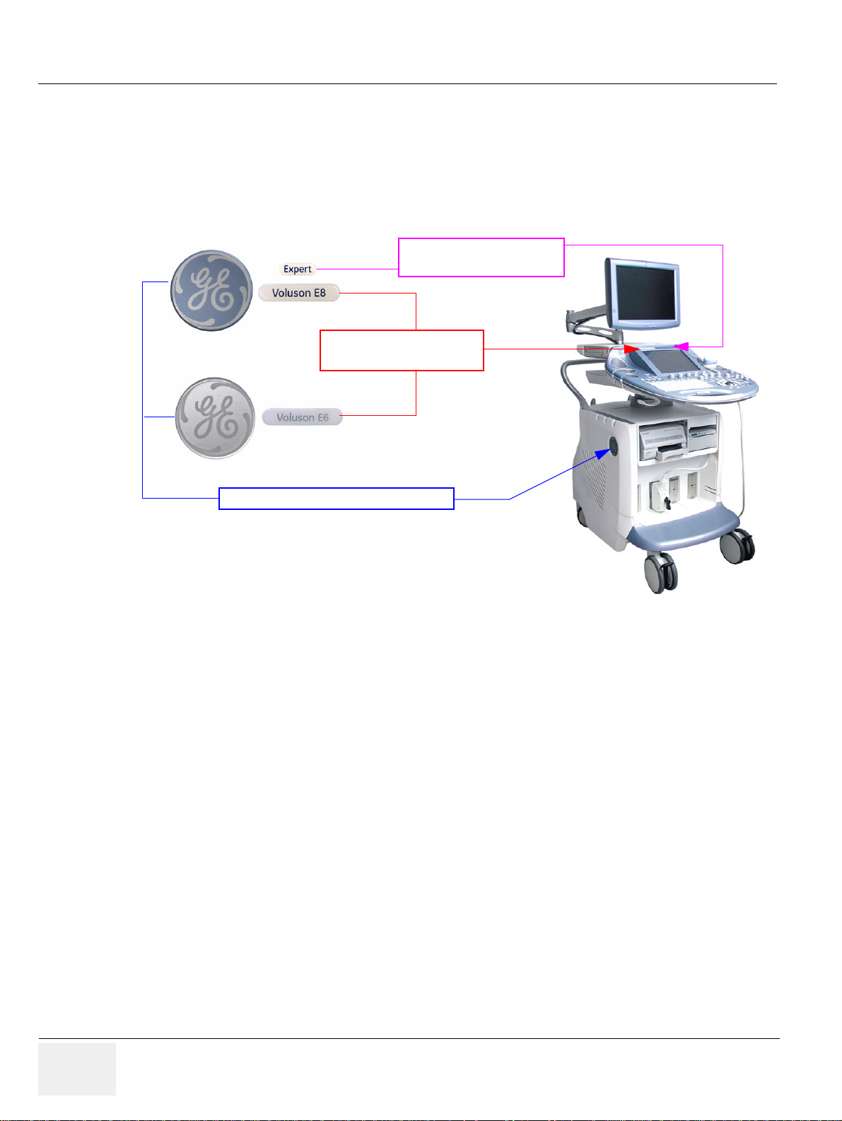
GE HEALTHCARERAFT VOLUSON E8 / VOLUSON E6
Voluson E* label
left above the Touch Panel
Expert label
right above the Touch Panel
GE Logo on the left and right side panel
D
IRECTION KTD102576, REVISION 7 DRAFT (AUGUST 23, 2012) SERVICE MANUAL
1-1-6-1 How to identify the Systems
Housing, Console and Monitor are the same, but labels and logos have different colors:
• Voluson E8 = blue
• Voluson E8 Expert = blue + additional Expert label
• Voluson E6 = silver
Figure 1-1 labels and logos have different colors
1-1-7 Purpose of Operator Manual(s)
The Operator Manual(s) should be fully read and understood before operating the Voluson E8 and/or
Voluson E6 and also kept near the system for quick reference.
The online versions of the operator manual is available via the Help function (F1 key) on the Voluson
E8 and/or Voluson E6 control panel.
The translated online user manuals are available on a CD ROM delivered with the system.
They are also available on the Common Documentation Library (CDL) for downloading.
1-6 Section 1-1 - Overview
Page 45
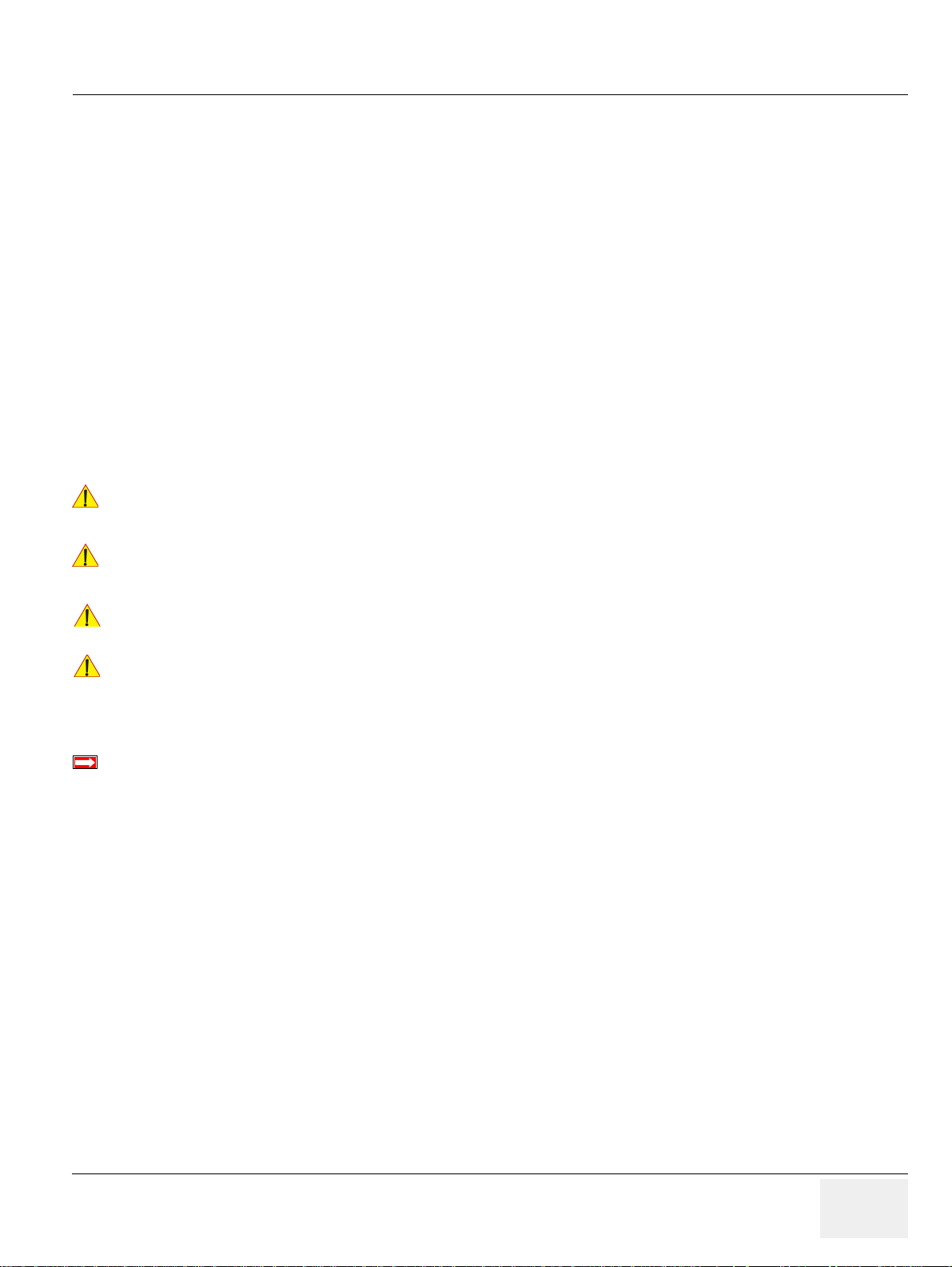
GE HEALTHCAREDRAFT VOLUSON E8 / VOLUSON E6
DANGER
WARNINGWARNING
CAUTION
NOTICE
BT Version:
D
IRECTION KTD102576, REVISION 7 DRAFT (AUGUST 23, 2012) SERVICE MANUAL
Section 1-2
Important Conventions
1-2-1 Conventions Used in this Manual
Model Designations
This manual covers the Voluson E8 / Voluson E6 ultrasound systems listed on page 1-2.
Icons
Pictures, or icons, are used wherever they reinforce the printed message. The icons, labels and
conventions used on the product and in the service information are described in this chapter.
Safety Precaution Messages
Various levels of safety precaution messages may be found on the equipment and in the service
information. The different levels of concern are identi fied by a flag word that precedes the precautionary
message. Known or potential hazards are labeled in one of following ways:
INDICATES THE PRESENCE OF A HAZARD THAT WILL CAUSE SEVERE
!! DANGER:
PERSONAL INJURY OR DEATH IF THE INSTRUCTIONS ARE IGNORED.
INDICATES THE PRESENCE OF A HAZARD THAT CAN CAUSE SEVERE PERSONAL
!! WARNING:
!! CAUTION:
!! NOTICE:
BT-Version:
NOTE: Notes provide important information about an item or a procedure.
INJURY AND PROPERTY DAMAGE IF INSTRUCTIONS ARE IGNORED.
Indicates the presence of a hazard that will or can cause minor personal injury and property
damage if instructions are ignored.
Equipment Damage Possible
Notice is used when a hazard is present that can cause property damage but has absolutely no
personal injury risk.
Example: Disk drive will crash.
Is used when options or features are specific for BT-Software versions.
Information contained in a NOTE can often save you time or effort.
Chapter 1 - Introduction 1-7
Page 46
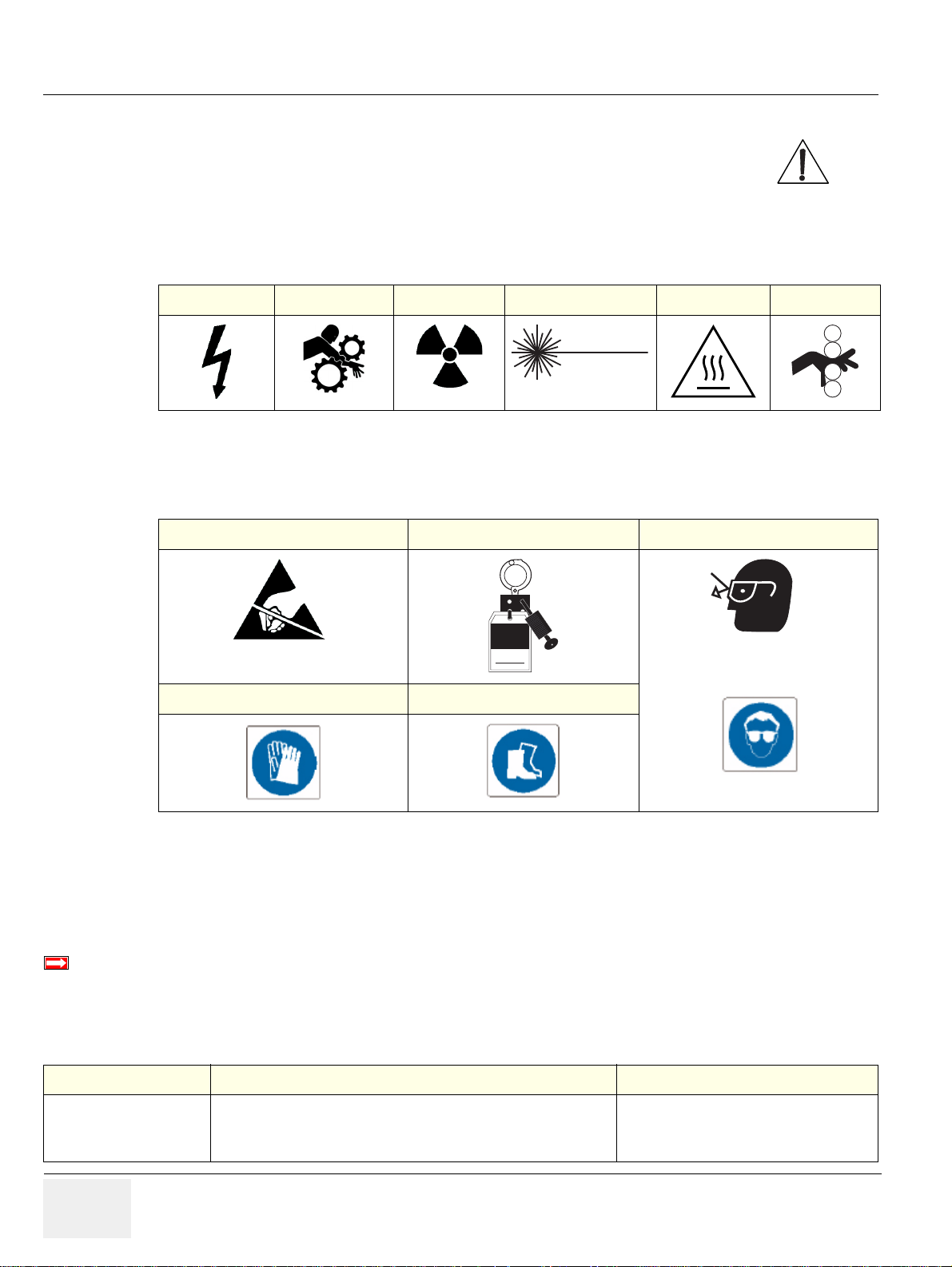
GE HEALTHCARERAFT VOLUSON E8 / VOLUSON E6
BT Version:
LASER
LIGHT
Signed
Date
TAG
&
LOCKOUT
EYE
PROTECTION
or
D
IRECTION KTD102576, REVISION 7 DRAFT (AUGUST 23, 2012) SERVICE MANUAL
1-2-2 Standard Hazard Icons
Important information will always be preceded by the exclamation point contained within
a triangle, as seen throughout this chapter. In addition to text, several differen t graphical
icons (symbols) may be used to make you aware of specific types of hazards that could
cause harm. Even if a symbol isn’t used in this manual, it is included for your reference.
Table 1-4 Standard Hazard Icons
ELECTRICAL MECHANICAL RADIATION LASER HEAT PINCH
Other hazard icons make you aware of specific procedures that should be followed.
Table 1-5 Standard Icons Indicating a Special Procedure be Used
AVOID STATIC ELECTRICITY TAG AND LOCK OUT WEAR EYE PROTECTION
WEAR HAND PROTECTION WEAR FOOT PROTECTION
1-2-3 Product Labels and Icons
The following table describes the purpose and location of labels, safety icons and other important
information provided on the equipment.
BT-Version:
Product labels and its location depend on BT-version and/or date of manufacture. For description of all
symbols and labels used on the system, refer to Chapter 2 in the Basic User Manual of your system.
Table 1-6 Product Labels and Icons
LABEL/SYMBOL PURPOSE/MEANING LOCATION
Identification and
Rating Plate
Manufacturer's name and address
Model and serial numbers
Electrical ratings
1-8 Section 1-2 - Important Conventions
rear side of system
on each probe
Page 47
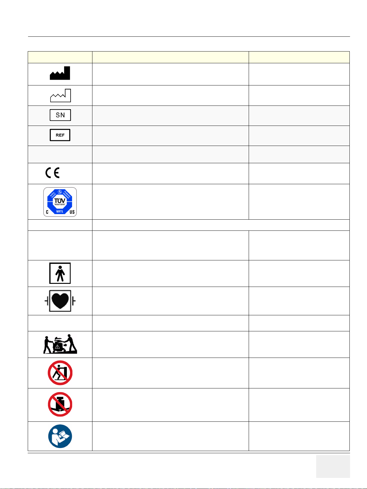
GE HEALTHCAREDRAFT VOLUSON E8 / VOLUSON E6
0123
D
IRECTION KTD102576, REVISION 7 DRAFT (AUGUST 23, 2012) SERVICE MANUAL
Table 1-6 Product Labels and Icons
LABEL/SYMBOL PURPOSE/MEANING LOCATION
Device Listing /
Certification Labels
Type/Class Label
IP Code (IPX 0)
IP Code (IPX 1)
IP Code (IPX 7)
Manufacturer’s name and address
Date of manufacture
Serial number
Catalog or model number
Laboratory logo or labels denoting conformance with industry safety
standards such as UL or IEC.
CE Conformity mark according to Medical Device Directive 93/42/EEC.
0123: Identification number of notified body TÜV Süd Product Service.
“Tested and production monitored by TÜV Product Service NRTL
with respect to ELECTRICAL SHOCK, FIRE and MECHANICAL
HAZARDS only in accordance with UL2601-1 and CAN/CSA C22.2
NO.601.1.”
Used to indicate the degree of safety or protection.
degree of protection provided by the enclosure per IEC 60529:
IPX 0 - no protection against ingress of water
IPX 1 - protected against dripping water
IPX 7 - protected against the effects of immersion
Identification and Rating Plate
(rear side of system / on plug of each probe)
Identification and Rating Plate
(rear side of system / on plug of each probe)
Identification and Rating Plate
(rear side of system / on plug of each probe)
Identification and Rating Plate
(rear side of system / on plug of each probe)
rear side of system
Identification and Rating Plate
(rear side of system / on plug of each probe)
Identification and Rating Plate
(rear side of system)
various
"DANGER -
Risk of explosion used in..."
Equipment Type BF (man in box, symbol IEC 60878-5333) indicates
B Type equipment having even more electrical isolation than standard
Type B equipment because it is intended for intimate patient contact.
Defibrillator-proof Type CF equipment (heart in box with “electrodes”,
symbol IEC 60878-5336) identifies a defibrillation-proof type CF
applied part complying with IEC 60601-1.
The system is not designed for use with flammable anesthetic gases. Indicated in the Service Manual.
This precaution is intended to prevent injury that may result if one
person attempt to move the system considerable distances or on an
incline due to the weight of the system.
Pushing prohibited.
Do not lean on the system. Tipping danger.
Take special care when moving the system.
Loading prohibited.
Do not put any items on this shelf. Danger of breaking.
Also items might be crushed when lowering the user interface.
“ATTENTION” - Read and understand all instructions for use”
This symbol advises the reader to consult the accompanying
documents (operator manual or other instructions).
Identification and Rating Plate
(rear side of system / on plug of each probe)
front side of the ECG-preamplifier
Used in the Service and User Manual which
should be adjacent to equipment at all times
for quick reference.
various
at top cover of system
rear side of system
Chapter 1 - Introduction 1-9
Page 48
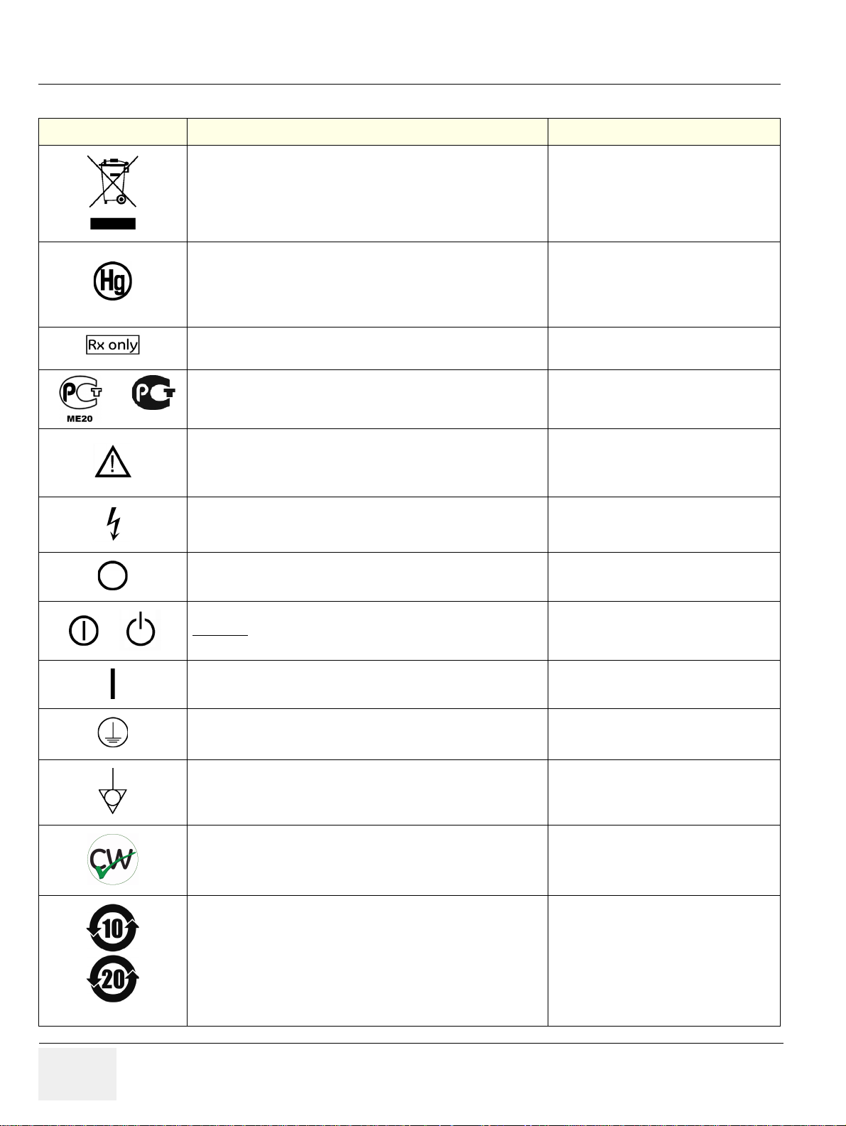
GE HEALTHCARERAFT VOLUSON E8 / VOLUSON E6
or
or
D
IRECTION KTD102576, REVISION 7 DRAFT (AUGUST 23, 2012) SERVICE MANUAL
Table 1-6 Product Labels and Icons
LABEL/SYMBOL PURPOSE/MEANING LOCATION
Waste Electrical and Electronic Equipment (WEEE) Disposal.
This symbol indicates that waste electrical and electronic equipment
must not be disposed as unsorted municipal waste and must be
collected separately.
Please contact an authorized representative of the manufacturer for
information concerning the decommissioning of your equipment.
Identification and Rating Plate
(rear side of system / on plug of each probe)
This product consists of devices that may contain mercury, which must
be recycled or disposed of in accordance with local, state, or country
laws. (Within this system, the backlight lamps in the monitor and the
Touch Panel display, contain mercury.)
This symbol indicates that in the United States of America, federal law
restricts this device to sale by or on the order of a physician.
GOST-R label (Russia Regulatory Country Clearance)
"CAUTION - Consult accompanying documents”
This symbol is used to advise the reader to consult the accompanying
documents for important safety-related information such as warnings
and pre-cautions that cannot be presented on the device itself.
"CAUTION - Dangerous electric voltage" (lightning flash with
arrowhead) is used to indicate electric shock hazards.
Unplug the main plug before opening the system!
"Mains OFF"
Indicates the power off position of the mains power switch.
"On/Off” or “Standby"
CAUTION:
disconnect the Voluson E8 / Voluson E6 from mains voltage!
System shutdown using this button DOES NOT
Identification and Rating Plate
(rear side of system)
not visible:
- below the cover on read side of Monitor
- on rear side of the Touch Panel
Identification and Rating Plate
(rear side of system)
Identification and Rating Plate
(rear side of system)
various
various
rear of system at mains switch
(on primary power supply - RTN)
ON/OFF Standby button on Control panel
"Mains ON"
Indicates the power on position of the mains power switch.
"Protective Earth"
Indicates the protective earth (grounding) terminal.
"Equipotential"
Indicates the terminal to be used for connecting equipotential
conductors when interconnecting (grounding) with other equipment.
This symbol indicates that the device is equipped with hardware for
using Continuous Wave Doppler.
These symbols indicate that at least one of the six hazardous
substances of the China RoHS Labelling Standard is above the RoHS
limitation. The number inside the circle is referred to as the
Environmental Friendly Use Period (EFUP). It indicates the number of
years that the product, under normal use, will remain harmless to
health of humans or the environment.
EFUP = 10 for Short Use Products
EFUP = 20 for Medium Use Products
1-10 Section 1-2 - Important Conventions
rear of system at mains switch
(on primary power supply - RTN)
rear of system at mains switch
(on primary power supply - RTN)
rear of system at mains switch
(on primary power supply - RTN)
rear side of system
rear side of system
on the plug of each probe
Page 49
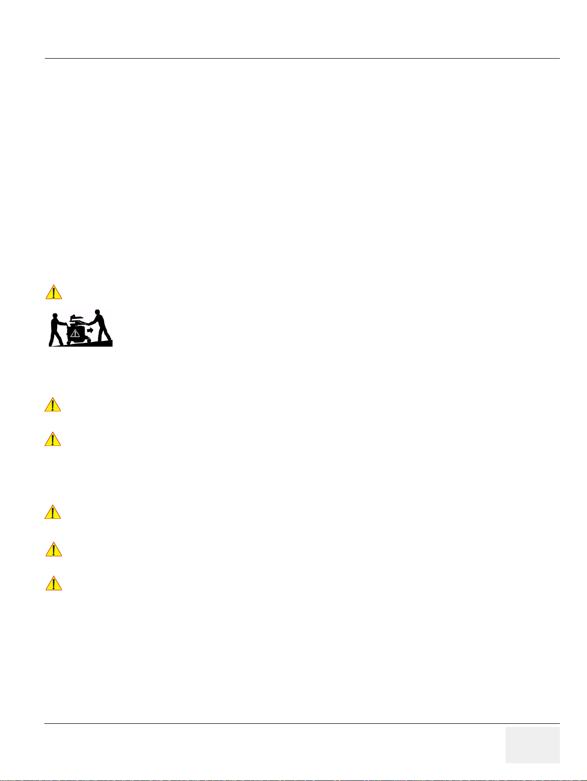
GE HEALTHCAREDRAFT VOLUSON E8 / VOLUSON E6
CAUTION
WARNINGWARNING
WARNINGWARNING
WARNINGWARNING
CAUTION
CAUTION
D
IRECTION KTD102576, REVISION 7 DRAFT (AUGUST 23, 2012) SERVICE MANUAL
Section 1-3
Safety Considerations
1-3-1 Introduction
The following safety precautions must be observed duri ng all phases of operation, service and repair of
this equipment. Failure to comply with these precautions or with specific warnings elsewhere in this
manual, violates safety standards of design, manufacture and intended use of the equipment.
1-3-2 Human Safety
• Operating personnel must not remove the system covers.
• Servicing should be performed by authorized personnel only.
Only personnel who have participated in a Voluson E8 / Voluson E6 Training are authorized to service
the equipment.
1-3-3 Mechanical Safety
The Voluson E8 / Voluson E6 weighs 130 kg or more, depending on installed peripherals, (300
!! CAUTION:
lbs., or more) when ready for use.
Care must be used when moving it or replacing its parts. Failure to follow the precautions
listed could result in injury, uncontrolled motion and costly damage.
ALWAYS:
• Use the handle to move the system. • Be sure the pathway is clear.
• Use slow, careful motions. • Do not let the system strike walls or door frames.
Two people are required when moving on inclines or lifting more than 16 kg (35 lbs).
WHEN THE SYSTEM IS RAISED FOR A REPAIR OR MOVED ALONG ANY INCLINE,
!! WARNING:
USE EXTREME CAUTION SINCE IT MAY BECOME UNSTABLE AND TIP OVER.
ULTRASOUND PROBES ARE HIGHLY SENSITIVE MEDICAL INSTRUMENTS THAT
!! WARNING:
CAN EASILY BE DAMAGED BY IMPROPER HANDLING. USE CARE WHEN
HANDLING AND PROTECT FROM DAMAGE WHEN NOT IN USE. DO NOT USE A
DAMAGED OR DEFECTIVE PROBE. FAILURE TO FOLLOW THESE PRECAUTIONS
CAN RESULT IN SERIOUS INJURY AND EQUIPMENT DAMAGE.
NEVER USE A PROBE THAT HAS FALLEN TO THE FLOOR.
!! WARNING:
!! CAUTION:
!! CAUTION:
NOTE: Special care should be taken when transporting the system in a vehicle:
EVEN IF IT LOOKS OK, IT MAY BE DAMAGED.
Always lower and center the control panel (UI) as much as possible before moving the
system. Always lock the control panel in its parking (locked) position.
Before you move or transport the system, make sure to lock the LCD monitor arm firmly and
flip down the monitor to prevent damage to the system.
• Eject any DVD/CD from the drive.
• Place the probes in their carrying cases.
• DO NOT use the control panel as an anchor point.
• Secure the systems with straps in an upright position and lock the caster wheels (brake).
• Ensure that the Voluson E8 / Voluson E6 system is firmly secured while inside the vehicle.
• Drive cautiously to prevent vibration damage.
Chapter 1 - Introduction 1-11
Page 50

GE HEALTHCARERAFT VOLUSON E8 / VOLUSON E6
WARNINGWARNING
WARNINGWARNING
WARNINGWARNING
BT Version:
D
IRECTION KTD102576, REVISION 7 DRAFT (AUGUST 23, 2012) SERVICE MANUAL
1-3-4 Electrical Safety
1-3-4-1 Safe Practices
To minimize shock hazard, the equipment chassis must be connected to an electrical ground.
The system is equipped with a three-conductor AC powe r cable. This must be plugged into an approved
electrical outlet with safety ground. If an extension co rd is used with the system, make sure that the total
current rating of the system does not exceed the extension cord rating.
The power outlet used for this equipment should not be shared with other types of equipment.
Both the system power cable and the power connector meet international electrical standards.
CONNECTING A VOLUSON E8 / VOLUSON E6 SCANNER TO THE WRONG VOLTAGE
!! WARNING:
1-3-4-2 Probes
LEVEL WILL MOST LIKELY DESTROY THE SCANNER.
All the probes for the Voluson E8 / Voluson E6 are d esigned and manufactured to provide trouble- free,
reliable service. To ensure this, correct handling of probes is important and the following points sho uld
be noted:
• Do not drop a probe or strike it against a ha rd surface, as this may damage the transducer elements,
acoustic lens, or housing.
• Inspect the probe prior to each use for damage or degradation to the Housing, Cable strain relief,
Lens and Seal.
• Do not use a cracked or damaged probe. In th is event, call GE ser vice represen tative imme diately
to obtain a replacement.
• Avoid pulling, pinching or kinking the probe cable, since a damaged cable may compromise the
electrical safety of the probe.
• To avoid the risk of a probe accidentally falling, do not allow the probe cables to become entangled,
or to be caught in the system’s wheels.
• Never immerse the probe connector or adapter into any liquid.
NOTE: For detailed information on handling probes, refer to the Voluson E8 / Voluson E6 Basic User Manual
and the care card supplied with the probe.
1-3-5 Auxiliary Devices Safety
Power Supplies for additional equipment MUST comply with IEC 60601-1.
!! WARNING:
DO NOT attempt to use different peripherals and accessories (brand and model;
!! WARNING:
1-12 Section 1-3 - Safety Considerations
connected via USB ports) other than approved and provided by GE Healthcare!
The ultrasound system is an extremely sensitive and complex medical system.
Any unauthorized peripherals may cause system failure or damage!
The Voluson E8 / Voluson E6 is equipped with an isolation transformer to provide the required
separation from mains for both, the system and the auxiliary devices.
One AUX main outlet is located at the primary power supply. It is used for connecting the threefold/
fourfold splitter whose outlets are led to the shelves intend for auxiliary devices (e.g., printers).
BT09 only: An AUX main outlet is accessible on the back of the control console.
The IEC 60601-1-1 standard provides a guideline for safely interconnecting medical devices in systems.
“Equipment connected to the analog or digital interface must comply with the respective IEC/UL
standards (e.g. IEC 60950 / UL 60950 for data processing equipment and IEC 60601-1 / UL 60601-1
for medical equipment).
Page 51
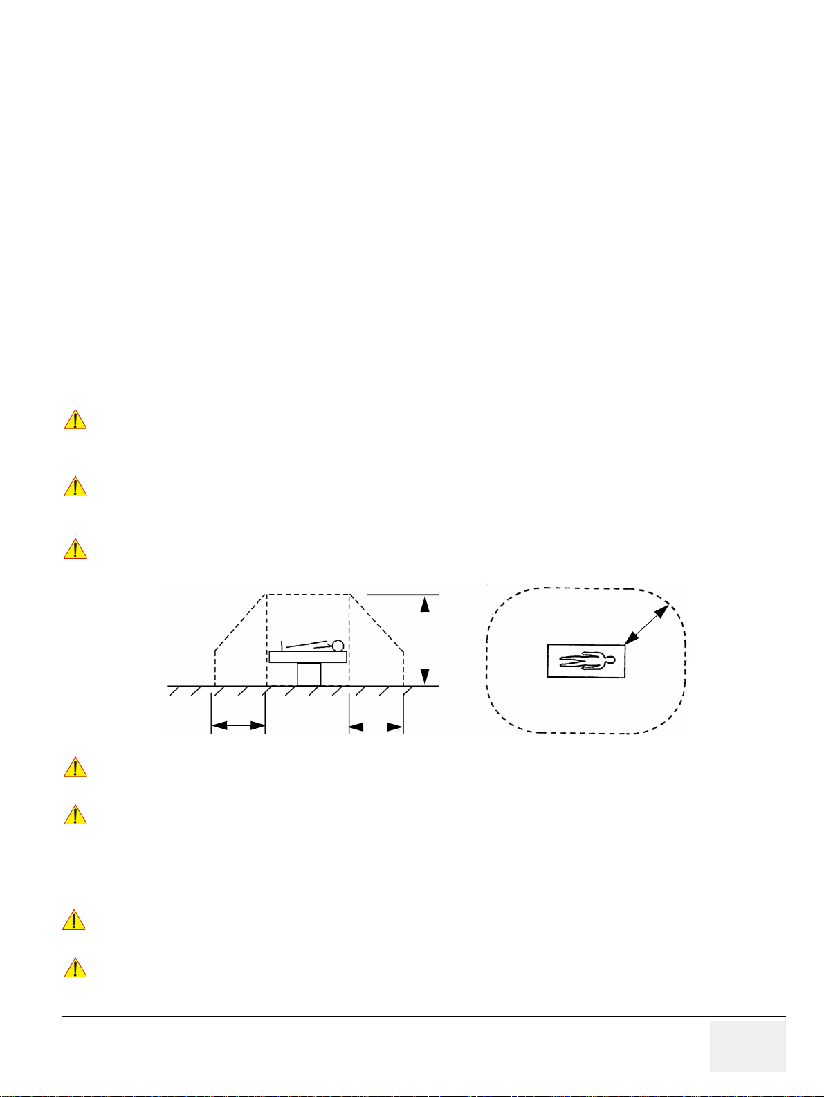
GE HEALTHCAREDRAFT VOLUSON E8 / VOLUSON E6
NOTICE
CAUTION
CAUTION
CAUTION
CAUTION
WARNINGWARNING
NOTICE
2,5 m
1,5 m
1,5 m1,5 m
D
IRECTION KTD102576, REVISION 7 DRAFT (AUGUST 23, 2012) SERVICE MANUAL
1-3-5 Auxiliary Devices Safety (cont’d)
Everybody who connects additional equipment to the signal input portion or signal output portion
configures a medical system, and is therefore re sp on sib le th at the syste m co mp lie s with th e
requirements of the system standard IEC 60601-1-1.
Special care has to be taken, if the device is connected to computer network (e.g., Ethernet), because
other devices could be connected without any control. There could be a potential difference between
the protective earth and any line of the computer network including the shield.
In this case the only way to operate the system safely is to use an isolated signal link with minimum
4mm creepage distance, 2.5mm air clearance of the isolation device. For computer netwo rks there are
media converters available which convert the electrical to optical signals. Please consider that this
converter has to comply with IEC xxx standards* and is battery operated or connected to the isolation
mains output of the Voluson E8 / Voluson E6 ultrasound system.
* IEC xxx stands for standards such as:
• IEC 60601 for medical devices
• IEC 60950 for information technology equipment etc.
The system integrator (any person connecting the medical device to other devices) is responsible
!! NOTICE:
that the connections are safe.
If in doubt, consult the technical service department or your local representative.
The leakage current of the entire system including any / all auxiliary equipment must not exceed
!! CAUTION:
the limit values as per EN 60601-1-1:1990 (IEC 60601-1-1) respectively other valid national or
international standards. All equipment must comply with UL, CSA and IEC requirements.
Please observe that some printers may not be medical devices! If the Bluetooth Printer and/or
!! CAUTION:
Line Printers are no medical devices, they have to be located outside of the patient environment
(according to IEC 60601-1 / UL 60601-1).
Auxiliary equipment must only be connected to the main console with the special main outlet
!! CAUTION:
provided for the electrical safety of the system.
Auxiliary equipment with direct main connection requires galvanic separation of the signal and/
!! CAUTION:
or control leads.
NOTE: Always observe the instructions given in the manual of the peripheral/auxiliary device.
!! WARNING:
!! NOTICE:
For hardware installation procedures see: Chapter 3 - Connection of Auxiliary Devices, on page 3-9.
After each installation, the leakage currents have to be measured according to
IEC 60601-1 respectively UL 60601-1.
All peripherals mounted on the Voluson E8 / Voluson E6 system chassis must be firmly secured in
position.
Chapter 1 - Introduction 1-13
Page 52
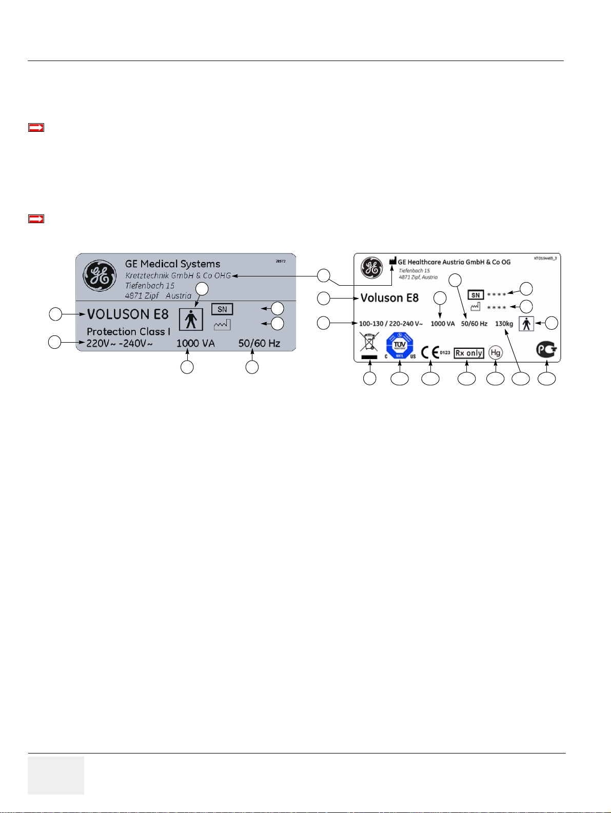
GE HEALTHCARERAFT VOLUSON E8 / VOLUSON E6
BT Version:
BT Version:
* * * *
* * * *
4
3
2
1
3
2
4
5
6
5
6
7
7
8
8
9
10 11 12 13 1514
D
IRECTION KTD102576, REVISION 7 DRAFT (AUGUST 23, 2012) SERVICE MANUAL
1-3-6 Labels Locations
The Voluson E8 / Voluson E6 ultrasound system comes equipped with product labels and icons.
These labels and icons represent pertinent information regarding the operation of the system.
BT-Version:
Product labels and its location depend on BT-version and/or date of manufacture.
Refer to Section 1-2-3 on page 1-8 and Chapter 2 in the Basic User Manual of your system.
1-3-6-1 Identification and Rating Plate
The Identification and Rating Plate is located on the rear of the Voluson E8 / Voluson E6 system.
BT-Version:
The layout of the Identification and Rating Plate depends on BT-version and/or date of manufacture.
Figure 1-2 Identification and Rating Plate: Examples
1 Manufacturer 5 System Serial Number 9 WEEE Disposal icon
2 Model Type 6 Manufacturing date 10 TUEV NRTL Certification mark
3 System Voltage range 7 Frequency 11 CE Conformity mark
4 Power Consumption nominal 8 Safety type: Type BF 12 FDA Guidance
1-14 Section 1-3 - Safety Considerations
13 Hg label
14 approx. weight of the system
15 GOST-R label
Page 53
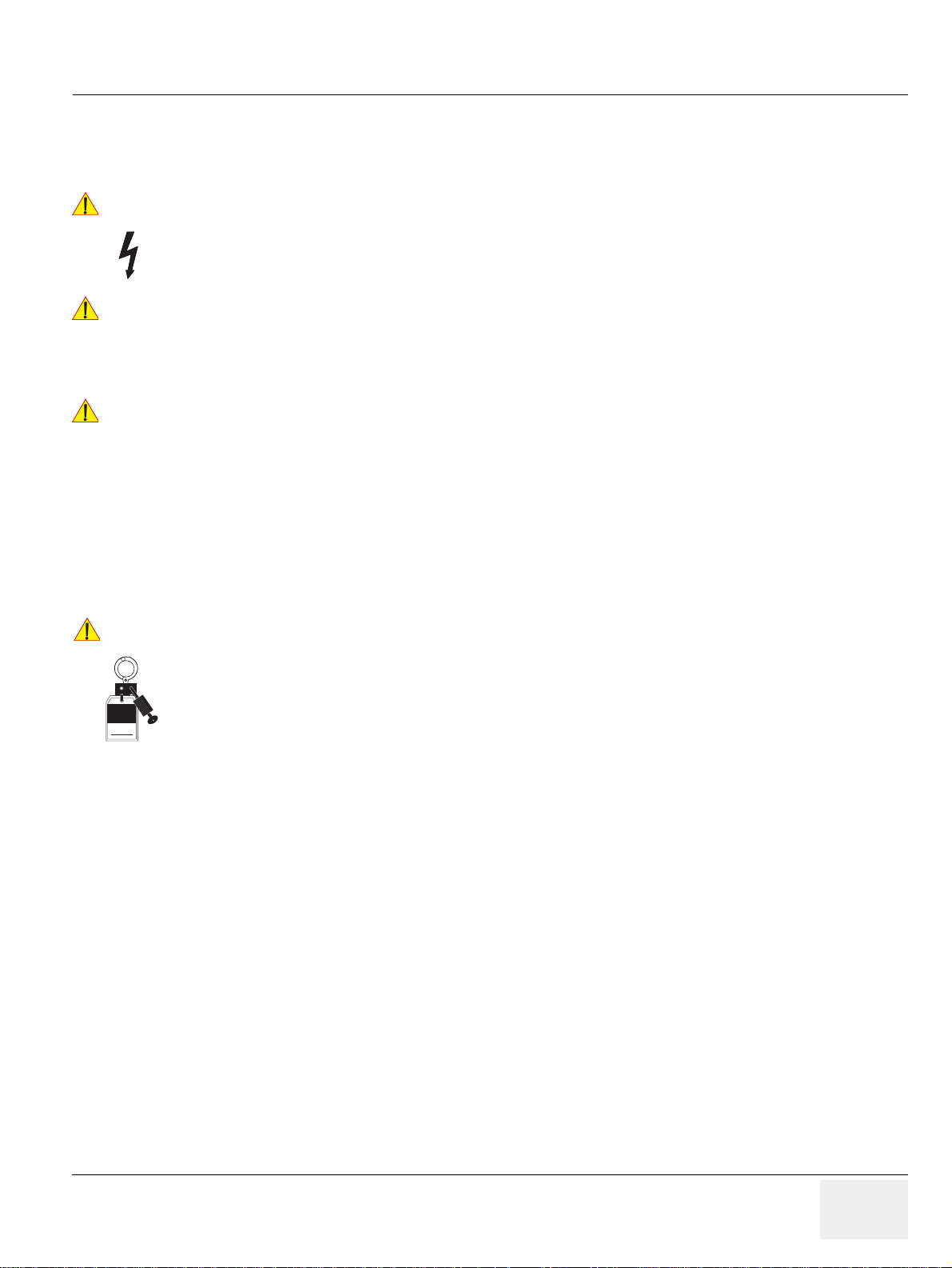
GE HEALTHCAREDRAFT VOLUSON E8 / VOLUSON E6
DANGER
WARNINGWARNING
WARNINGWARNING
NOTICE
Signed
Date
TAG
&
LOCKOUT
D
IRECTION KTD102576, REVISION 7 DRAFT (AUGUST 23, 2012) SERVICE MANUAL
1-3-7 Dangerous Procedure Warnings
Warnings, such as the examples below, precede potentially dangerous procedures throughout this
manual. Instructions contained in the warnings must be followed.
DANGEROUS VOLTAGES, CAPABLE OF CAUSING DEATH, ARE PRESENT
!! DANGER:
IN THIS EQUIPMENT.
USE EXTREME CAUTION WHEN HANDLING, TESTING AND ADJUSTING.
EXPLOSION WARNING
!! WARNING:
!! WARNING:
DO NOT OPERATE THE EQUIPMENT IN AN EXPLOSIVE ATMOSPHERE.
OPERATION OF ANY ELECTRICAL EQUIPMENT IN SUCH AN ENVIRONMENT
CONSTITUTES A DEFINITE SAFETY HAZARD.
DO NOT SUBSTITUTE PARTS OR MODIFY EQUIPMENT
BECAUSE OF THE DANGER OF INTRODUCING ADDITIONAL HAZARDS, DO NOT
INSTALL SUBSTITUTE PARTS OR PERFORM ANY UNAUTHORIZED MODIFICATION
OF THE EQUIPMENT.
1-3-8 Lockout/Tagout Requirements (For USA Only)
Follow OSHA Lockout/Tagout requirements to protect service personnel from injuries caused by
unexpected energizing or start-up of equipment during service, repair, or maintenance.
Energy Control and Power Lockout for Voluson E8 / Voluson E6.
!! NOTICE:
When servicing parts of the system where there is exposure to voltage greater than 30 Volts:
Unplug the system.
Maintain control of the system power plug.
There are no test points to verify isolation, you must wait for at least 20 seconds for capacitors to
discharge.
Beware that the Power Supply, Front End Processor and Back End Processor may be energized even
if the power is turned off when the cord is still plugged into the AC Outlet.
1-3-9 Returning/Shipping System, Probes and Repair Parts
When returning or shipping the Voluson E8 / Voluson E6 system in the original packaging:
• system must be lowered to its minimum height with mo nitor flapped do wn (see Figur e on p age 3- 6)
• the Control Console has to be centered and locked in “unextended” position
NOTE: For Control Console Positioning refer to Section 6-5 on page 6-7.
Equipment being returned must be clean and free of blood and other infectious substances.
UT
GEHC policy states that body fluids must be properly removed from any part or equipment prior to
shipment. GEHC employees, as well as customers, are responsible for ensuring that parts/equipment
have been properly decontaminated prior to shipment. Under no circumstance should a part or
equipment with visible body fluids be taken or shipped from a clinic or site (for example, body coils or
and ultrasound probe).
The purpose of the regulation is to protect employees in the transportation industry, as well as the
people who will receive or open this package.
Chapter 1 - Introduction 1-15
Page 54

GE HEALTHCARERAFT VOLUSON E8 / VOLUSON E6
WARNINGWARNING
WARNINGWARNING
D
IRECTION KTD102576, REVISION 7 DRAFT (AUGUST 23, 2012) SERVICE MANUAL
1-3-9 Returning/Shipping System, Probes and Repair Parts (cont’d)
NOTE: The US Department of Transportation (DOT) h as ruled that “items what were saturated and/or dripping
with human blood that are now caked with dried blood; or which were used or intended for use in patient
care” are “regulated medical waste” for transportation purpo se and must be transported as a hazardous
material.
Section 1-4
Electromagnetic Compatibility (EMC)
1-4-1 What is EMC?
Electromagnetic compatibility describes a level of performance of a device within its electromagnetic
environment. This environment consists of the device itself and its surroundings including other
equipment, power sources and persons with which the device must interface. Inadequate compatibility
results when a susceptible device fails to perform as intended due interference from its environment or
when the device produces unacceptable levels of emission to its environment. This interference is often
referred to as radio–frequency or electromagnetic interference (RFI/EM I) an d can be rad iated th rough
space or conducted over interconnecting power of signal cables. In ad dition to electromagnetic energy,
EMC also includes possible effects from electrical fields, magnetic fields, electrostatic discharge and
disturbances in the electrical power supply.
For applicable standards please refer to Chapter 2 in the Basic User Manual of the Volu son E8 /
Voluson E6 ultrasound system.
1-4-2 Compliance
The Voluson E8 / Voluson E6 system conforms to all applicable conducted and radiated emission limits
and to immunity from electrostatic discharge, radiated and conducted RF fields, magnetic fields and
power line transient requirements as mentioned in IEC 60601-1-2.
NOTE: For CE Compliance , it is critical that all covers, sc rews, shielding, gaskets, mesh, cla mps, are in
good condition, installed tightly without skew or stress. Proper installation following all
comments noted in this service manual is required in order to achieve full EMC performance.
1-4-3 Electrostatic Discharge (ESD) Prevention
DO NOT touch any boards with integrated circuits prior to taking the necessary ESD
!! WARNING:
!! WARNING:
precautions:
1.) When installing boards, ESD may cause damage to a board.
ALWAYS connect yourself, via an arm-wrist strap, to the advised ESD connection
point located on the rear of the system (to the right of the power connector).
2.) Follow general guidelines for handling of electrostatic sensitive equipment.
Risk of electrical shock: System must be turned off.
Avoid all contact with electrical contacts, conductors and components.
Always use non-conductive handles designed for the removal and rep lacement of ESD
sensitive parts. All parts that have the potential for storing energy must be discharged
or isolated before making contact.
1-16 Section 1-4 - Electromagnetic Compatibility (EMC)
Page 55
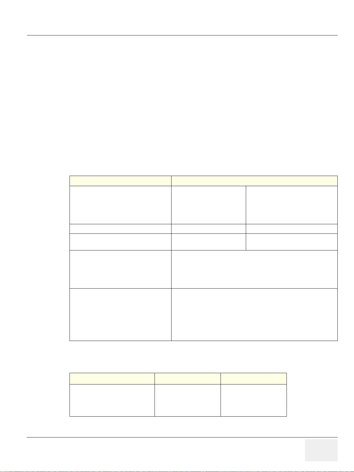
GE HEALTHCAREDRAFT VOLUSON E8 / VOLUSON E6
D
IRECTION KTD102576, REVISION 7 DRAFT (AUGUST 23, 2012) SERVICE MANUAL
Section 1-5
Customer Assistance
1-5-1 Contact Information
If this equipment does not work as indicated in this service manual or in the Basic User Manual, or if
you require additional assistance, please contact the local distributor or appropriate support resource,
as listed below.
NOTE: Prepare vital system information (see: Section 7-2 on page 7-2) before you call:
•System Type
• System Serial number (also visible on label on back of the system)
• Application Software version
• Backup version
• additional information about installed software
Table 1-7 Phone Numbers for Customer Assistance
Location Phone Number
USA
GE Medical Systems
Ultrasound Service Engineering
9900 Innovation Drive (RP-2123)
Wauwatosa, WI 53226, USA
Canada 1-800-668-0732
Latin America
Europe
GE Ultraschall Deutschland GmbH
Beethovenstraße 239
Postfach 11 05 60, D-42655 Solingen
Germany
Online Services Ultrasound Asia
Australia
China
India
Japan
Korea
Singapore
Service On-site
Service: Parts
Applications support
Service
Applications support
OLC - EMEA (Europe, Middle East & Africa)
Phone: +49 (0) 212 2802 - 652 (-OLC)
+33 1 3083 1300 (English/German all segments incl. training)
Fax: +49 (0) 212 2802 - 431
Phone: +(61) 1-800-647-855
+(86) 800-810-8188
+(91) 1800-425-8025
+(81) 42-648-2940
+(82) 2620 13585
+(95) 6277-3444
1-800–437–1171
1-800-558-2040
1-800-682-5327 or 1-262-524-5698
1-800-321-7937
1-262-524-5698
1-5-2 System Manufacturer
Table 1-8 System Manufacturer
Manufacturer Telephone FAX
GE Healthcare Austria GmbH & Co OG
Tiefenbach 15
A-4871 Zipf
Austria - Europe
+43 (0) 7682-3800-0 +43 (0) 7682-3800-47
Chapter 1 - Introduction 1-17
Page 56

GE HEALTHCARERAFT VOLUSON E8 / VOLUSON E6
D
IRECTION KTD102576, REVISION 7 DRAFT (AUGUST 23, 2012) SERVICE MANUAL
This page was intentionally left blank.
1-18 Section 1-5 - Customer Assistance
Page 57

GE HEALTHCAREDRAFT VOLUSON E8 / VOLUSON E6
D
IRECTION KTD102576, REVISION 7 DRAFT (AUGUST 23, 2012) SERVICE MANUAL
Chapter 2
Site Preparation
Section 2-1
Overview
2-1-1 Purpose of this Chapter
This chapter provides the information required to plan and prepare for the installation of a Voluson E8
/ Voluson E6 ultrasound system. Included are descriptions of the facility and electrical needs to be met
by the purchaser.
2-1-2 Contents in this Chapter
2-1 Overview. . . . . . . . . . . . . . . . . . . . . . . . . . . . . . . . . . . . . . . . . . . . . . . . . . . . . . . . . . . . . 2-1
2-2 General Console Requirements . . . . . . . . . . . . . . . . . . . . . . . . . . . . . . . . . . . . . . . . . . . 2-2
2-3 Facility Needs. . . . . . . . . . . . . . . . . . . . . . . . . . . . . . . . . . . . . . . . . . . . . . . . . . . . . . . . . 2-6
Chapter 2 - Site Preparation 2-1
Page 58
GE HEALTHCARERAFT VOLUSON E8 / VOLUSON E6
CAUTION
D
IRECTION KTD102576, REVISION 7 DRAFT (AUGUST 23, 2012) SERVICE MANUAL
Section 2-2
General Console Requirements
2-2-1 Environmental Requirements
Table 2-1 Environmental Requirements
Operating
Temperature
10 to 30oC
o
(50 to 86
F)
Operating
Humidity Heat Dissipation
30 to 80% rH
non-condensing
3410 BTU/hour
Storage
Temperature Storage Humidity
-10 to 40
(14 to 104
o
C
o
F)
If the system has been in storage or has been transported, please see the acclimation requirements
!! CAUTION:
before powering
ON and/or using the system (see: Section 3-2-2 "Installation Warnings" on page 3-2).
2-2-1-1 Cooling
The cooling requirement for the Voluson E8 / Voluson E6 is 3410 BTU/hr. This figure does not include
cooling needed for lights, people, or other equipment in the room.
NOTE: Each person in the room places an additional 300 BTU/hr. demand on the cooling system.
2-2-1-2 Lighting
Bright light is needed for system installation, updates and repairs. However, operator and patient
comfort may be optimized if the room light is subdued and indirect. Therefore a combination lighting
system (dim/bright) is recommended. Keep in mind that lighting controls and dimmers can be a source
of EMI which could degrade image quality. These controls should be selected to minimize possible
interference.
2-2-2 Electrical Requirements
< 90% rH non-
condensing
NOTE: GE Healthcare requires a dedicated powe r and ground for the proper operation of its Ultrasound
equipment. This dedicated power shall originate at the last distribution panel before the system.
The dedicated line shall consist of one phase, a neutral (not shared with any other circuit), and a full
size Ground wire from the distribution panel to the Ultrasound outlet.
NOTE: Please note that image artifacts can occur, if at any time within the facility, the Ground from the main
facility's incoming power source to the Ultrasound system is only a conduit.
2-2 Section 2-2 - General Console Requirements
Page 59
GE HEALTHCAREDRAFT VOLUSON E8 / VOLUSON E6
CAUTION
CAUTION
D
IRECTION KTD102576, REVISION 7 DRAFT (AUGUST 23, 2012) SERVICE MANUAL
2-2-2-1 Voluson E8 / Voluson E6 Power Requirements
Table 2-2 Electrical Specifications for Voluson E8 / Voluson E6
Voltage Tolerances Current Frequency
100 - 130 VAC ±10% 10.0 ... 7.7 A 50, 60 Hz (±2%)
220 - 240 VAC ±10% 4.5 ... 4.2 A 50, 60 Hz (±2%)
Power Consumption nominal 1000 VA including all options.
Mains outlet: Mains socket AUX for accessories.
All mains outlets are co-switched by the system’s mains switch via built-in isolation transformer.
Output voltage for AUX: 115V or 230V.
Modification of voltage setting only by an authorized service person!
!! CAUTION:
The maximum power consumption of equipment (inclusive of the color LCD monitor) connected
to these outlets must not exceed 345VA!
2-2-2-2 Inrush Current
Inrush current is not a factor to consider due to the inrush current limiting properties of the power
supplies.
2-2-2-3 Site Circuit Breaker
It is recommended that the branch circuit breaker for the system be readily accessible.
POWER OUTAGE MAY OCCUR.
!! CAUTION:
The Voluson E8 / Voluson E6 requires a dedicated single branch circuit. To avoid circuit
overload and possible loss of critical care equipment, make sure you DO NOT have any other
equipment operating on the same circuit.
2-2-2-4 Site Power Outlets
A dedicated AC power outlet must be within reach of the system without extension cords. Other
adequate outlets for the external peripherals, medica l and test equipment needed to support this system
must also be present within 1 m (3.2 ft.) of the system. Electrical installation must meet all current local,
state, and national electrical codes.
2-2-2-5 Main Power Plug
The Voluson E8 / Voluson E6 ultrasound system is supplied with a main power plug, as sta ndard. In the
event that the system arrives without a power plug, or with the wrong plug, contact your GE dealer.
When necessary, the installation engineer will supply the appropriate power plug to meet the applicable
local regulations.
Chapter 2 - Site Preparation 2-3
Page 60
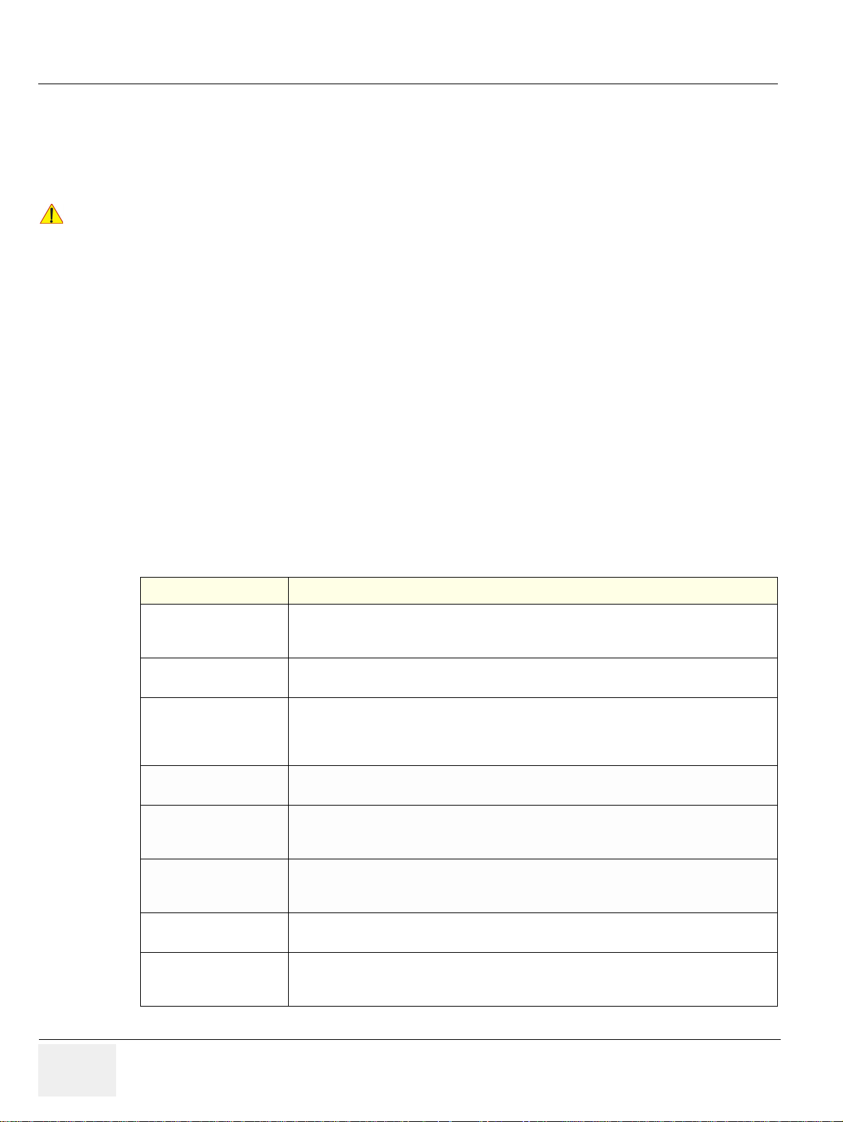
GE HEALTHCARERAFT VOLUSON E8 / VOLUSON E6
NOTICE
D
IRECTION KTD102576, REVISION 7 DRAFT (AUGUST 23, 2012) SERVICE MANUAL
2-2-3 EMI Limitations
Ultrasound systems are susceptible to Electromagnetic Interference (EMI) from radio frequencies,
magnetic fields, and transients in the air or wiring. Ultrasound systems also generate EMI.
The Voluson E8 / Voluson E6 complies with limits as stated on the EMC label. However, there is no
guarantee that interference will not occur in a particular installation.
Possible EMI sources should be identified before the system is installed.
!! NOTICE:
Electrical and electronic equipment may produce EMI unintentionally as the result of a defect.
Sources of EMI include the following:
• medical lasers
• scanners
• cauterizing guns
•computers
•monitors
• fans
• gel warmers
• microwave oven
• light dimmers
• portable phones
• broadcast stations and mobile broadcasting machines
Table 2-3 EMI Prevention/Abatement
EMI Rule Details
Keep the system at least 5 meters (16.4 feet) away from other EMI sources. Special shielding may
Be aware of RF sources.
Ground the system.
Replace and/or reassemble
all screws, RF gaskets,
covers and cores.
Replace broken RF gaskets.
Do not place labels where
RF gaskets touch metal.
Use GE- specified
harnesses and peripherals.
Take care with cellular
phones.
Properly dress peripheral
cables.
be required to eliminate interference problems caused by high frequency, high powered radio or
video broadcast signals.
Poor grounding is the most likely reason a system will have noisy images.
Check grounding of the power cord and power outlet.
After you finish repairing or updating the system, replace all covers and tighten all screws.
Any cable with an external connection requires a magnet wrap at each end.
Install the shield over the front of card cage. Loose or missing covers or RF gaskets allow radio
frequencies to interfere with the ultrasound signals.
If more than 20% or a pair of the fingers on an RF gasket are broken, replace the gasket.
Do not turn ON the system until any loose metallic part is removed and replaced, if required.
Never place a label where RF gaskets meet the system. Otherwise, the gap created will permit RF
leakage. In case a label has been found in such a location, move the label to a different,
appropriate location.
The interconnect cables are grounded and require ferrite beads and other shielding.
Cable length, material, and routing are all important; do not make any changes that do not meet
all specifications.
Cellular phones may transmit a 5 V/m signal that causes image artifacts.
Do not allow cables to lie across the top of the card cage or hang out of the peripheral bays.
Loop the excess length for peripheral cables inside the peripheral bays.
Attach the monitor cables to the frame.
2-4 Section 2-2 - General Console Requirements
Page 61
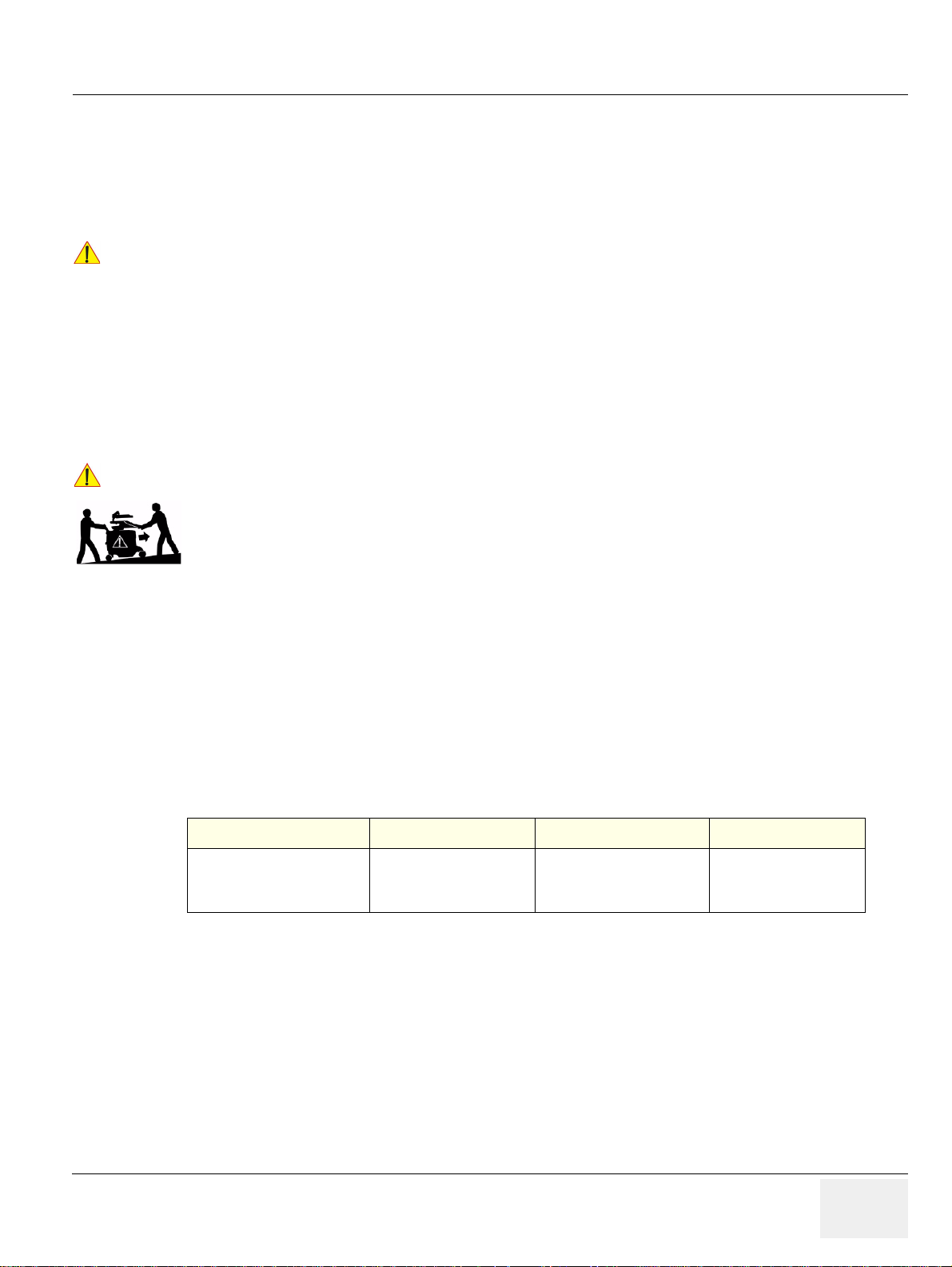
GE HEALTHCAREDRAFT VOLUSON E8 / VOLUSON E6
NOTICE
CAUTION
D
IRECTION KTD102576, REVISION 7 DRAFT (AUGUST 23, 2012) SERVICE MANUAL
2-2-4 Probe Environmental Requirements
Operation: Ambient temperature 18° to 30° C
Storage: -10° to 50° C
NOTE: Temperature in degrees C. Conversion to degrees F = °C (9/5) + 32).
SYSTEMS AND ELECTRONIC PROBES ARE DESIGNED FOR STORAGE TEMPERATURES OF
!! NOTICE:
-10 TO + 50 degrees C. WHEN EXPOSED TO LARGE TEMPERATURE VARIATIONS, THE
PRODUCT SHOULD BE KEPT IN ROOM TEMPERATURE FOR 10 HOURS BEFORE USE.
2-2-5 Time and Manpower Requirements
Site preparation takes time. Begin Pre-installation checks as soon as possible. If possible, allow six
weeks before delivery, for enough time to make necessary changes.
Have two people available to deliver and unpack the Voluson E8 / Voluson E6 ultrasound
!! CAUTION:
system.
Attempts to move the system considerable distances (or on an incline) by one person alone,
could result in personal injury and/or damage to the system.
2-2-6 System Specifications
2-2-6-1 Physical Dimensions of Voluson E8 / Voluson E6
The physical dimensions and weight (without Peripherals) of the Voluson E8 / Voluson E6 system are
summarized in Table 2-4.
NOTE: Physical dimensions (especially height and depth) depend on control co nsole and monitor positioning.
For more details refer to Chapter 5 - Control Console Positioning, on page 5-63.
Table 2-4 Physical Dimensions and Weight (without Monitor and Peripherals)
Height Width Depth Weight
1520 mm / 59.9 inch *
1320 mm / 52.0 inch **
1120 mm / 44.1 inch ***
*
maximum at “normal” Monitor position (control console is elevated and moved forwards to the maximum)
**
minimum at “normal” Monitor position (no control console elevation or forwards movement)
***
absolute minimum (Monitor flapped down)
2-2-6-2 Acoustic Noise Output
max. 55 dB(A)
2-2-6-3 Electrical Specifications
Please refer to Section 2-2-2-1 "Voluson E8 / Voluson E6 Power Requirements" on page 2-3.
580 mm / 22.8 inch 1160 mm / 45.6 inch *
960 mm / 37.8 inch **
130 kg / 286.6 lbs.
Chapter 2 - Site Preparation 2-5
Page 62
GE HEALTHCARERAFT VOLUSON E8 / VOLUSON E6
D
IRECTION KTD102576, REVISION 7 DRAFT (AUGUST 23, 2012) SERVICE MANUAL
Section 2-3
Facility Needs
2-3-1 Purchaser Responsibilities
The work and materials needed to prepare the site is the responsibility of the purchaser. Delay,
confusion, and waste of manpower can be avoided by completing pr e installation wo rk before delive ry.
Use the Pre-installation checklist (provided in Table 2-5) to verify that all needed steps have been taken.
Table 2-5 Voluson E8 / Voluson E6 Pre-Installation Check List
Action Yes No
Schedule at least 3 hours for installation of the system.
Notify installation team of the existence of any variances from the basic installation.
Make sure system and probes have been subject to acclimation period.
Environmental cooling is sufficient.
Lighting is adjustable to adapt to varying operational conditions of the scanner.
Electrical facilities meet system requirements.
EMI precautions have been taken and all possible sources of interference have been removed.
Mandatory site requirements have been met.
If a network is used, IP address has been set for the system and a dedicated network outlet is available.
Purchaser responsibility includes:
• Procuring the materials required.
• Completing the preparations befo re de livery of the ultrasound system.
• Paying the costs for any alterations and modification s not specifically provided in the sales contract.
NOTE: All electrical installations that are preliminary to the positioning of the equipment at the site prepared for
the equipment must be performed by licensed electrical contractors. Oth er connections between pieces
of electrical equipment, calibrations, and testing must also be performed by qualified personnel.
The products involved (and the accompanying electrical installations) are highly sophisticated and
special engineering competence is required. All electrical work on these produ cts must comply with the
requirements of applicable electrical codes. The purchaser of GE equipment must only utilize qualified
personnel to perform electrical servicing on the equipment.
The desire to use a non–listed or customer provided product or to place an approved product further
from the system than the interface kit allows pr esents challenges to the installation team. To avoid
delays during installation, such variances should be made known to the in dividuals or group performing
the installation at the earliest possible date (preferably prior to the purchase).
The ultrasound suite must be clean prior to delivery of the system. Carpet is not recommended because
it collects dust and creates static. Potential sources of EMI (electromagnetic interference) should also
be investigated before delivery. Dirt, static, and EMI can negatively impact system reliability.
2-6 Section 2-3 - Facility Needs
Page 63

GE HEALTHCAREDRAFT VOLUSON E8 / VOLUSON E6
D
IRECTION KTD102576, REVISION 7 DRAFT (AUGUST 23, 2012) SERVICE MANUAL
2-3-2 Mandatory Site Requirements
The following are mandatory site requirements. Additional (optional) recommendations, as well as a
recommended ultrasound room layout, are provided in Section 2-3 -3 "Site Recommendations".
• A dedicated single branch power outlet of adequate amperage (see Table 2-2 on page 2-3) that
meets all local and national codes and is located less than 2.5 m (8.2 ft) from the system’s proposed
location. Refer to: Section 2-2-2 "Electrical Requirements" on page 2-2.
• A door opening of at least 76 cm (2.5 ft) in width.
• The proposed location for the system is at least 0.2 m (0.67 ft) from the walls, to enable cooling.
• Clean and protected space for storage of probes (either in their case or on a rack).
• Material to safely clean probes (perform ed usin g a pla stic con tain e r, ne ve r me ta l).
• Power outlet and place for any external peripheral are within 2 m (6.5 ft.) of each other with
peripheral within 1 m of the system to connect cables.
NOTE: The Voluson E8 / Voluson E6 has four outlets inside the system. One is for the monitor and three for on
board peripherals.
In case of network option:
• An active network outlet in the vicinity of the ultrasound system.
• A network cable of appropriate length (regular Pin-to-Pin network cable).
• An IT administrator who will assist in configuring the system to work with your local network.
A fixed IP address is required. Refer to the form provided in Figure 3-66 on page 3-69 for network
details that are required.
NOTE: All relevant preliminary network port installations at the prepared site must be perfor med by authorized
contractors. The purchaser of GE equipment must utilize only qualified personnel to perform servicing
of the equipment.
2-3-3 Site Recommendations
The following are (optional) site recommendations. Mandatory site requirements are provided in the
Mandatory Site Requirements section, above.
• Door opening of 90 cm (3 ft) in width.
• Accessible circuit breaker for a dedicated power outlet.
• Sink with hot and cold running water.
• Receptacle for bio–hazardous waste, for example, used probe sheaths.
• Emergency oxygen supply.
• Storage area for linens and equipment.
• Nearby waiting room, lavatory, and dressing room.
• Dual level lighting (bright and dim).
• Lockable cabinet for software and manuals.
Chapter 2 - Site Preparation 2-7
Page 64
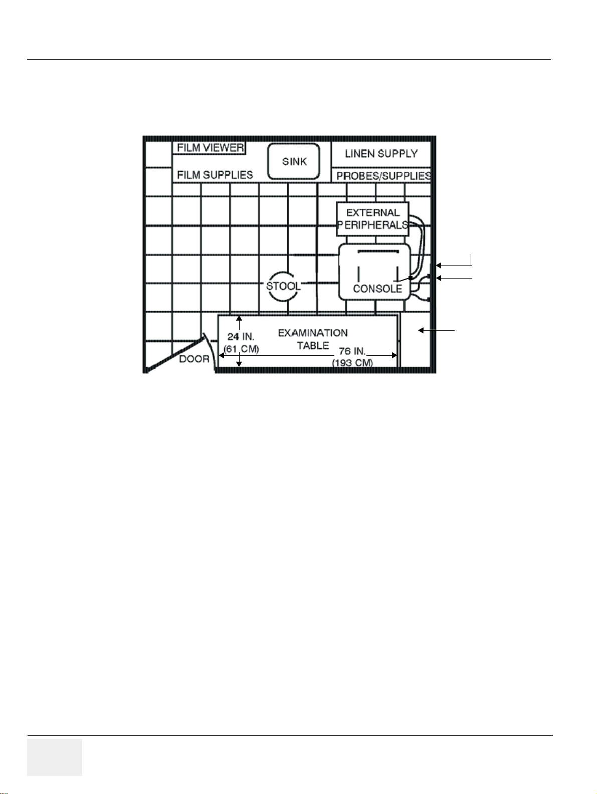
GE HEALTHCARERAFT VOLUSON E8 / VOLUSON E6
35.5 IN.
(92 CM)
Dedicated Power Outlets
Hospital Network
Cabinet for
Software and Manuals
(optional)
VOLUSON E8
D
IRECTION KTD102576, REVISION 7 DRAFT (AUGUST 23, 2012) SERVICE MANUAL
2-3-3-1 Recommended Ultrasound Room Layout
Figure 2-1 below shows a floor plan illustrating the recommended layout of the Ultrasound Room and
depicting the minimal room layout requirements.
Figure 2-1 Recommended Floor Plan 4.3m x 5.2m (14ft x 17ft)
2-8 Section 2-3 - Facility Needs
Page 65

GE HEALTHCAREDRAFT VOLUSON E8 / VOLUSON E6
D
IRECTION KTD102576, REVISION 7 DRAFT (AUGUST 23, 2012) SERVICE MANUAL
2-3-4 Networking Setup Requirements
2-3-4-1 Stand-alone system (without Network Connection)
None
2-3-4-2 Unit Connected to Hospital’s Network
Supported networks:
• Ethernet
• Wireless LAN
2-3-4-3 Purpose of the DICOM Network Function
DICOM (Digital Imaging and Communications in Medicine) services provide the operator with clinically
useful features for moving images and patient information over a hospital network.
Examples of DICOM services include the transfer of images to workstations for viewing or transferring
images to remote printers. As an added benefit, transferring images in this manner frees up the onboard monitor and peripherals, enabling viewing to be done while scanning continues.
With DICOM, images can be archived, stored, and retrieved faster, easier, and at a lower cost.
2-3-4-4 DICOM Option Pre-installation Requirements
To configure the Voluson E8 / Voluson E6 ultrasound system to work with other network connections,
the network administrator must provide some necessary information.
Use the Connectivity Setup Worksheet on page 3-68 to record re quired information that must include:
• Voluson E8 / Voluson E6
Details:
• Routing Information: IP addresses for default gateway and other routers in use at site.
• DICOM Application Information: Details of DICOM devices in use at the site, including the DICOM
Installation see: Section 3-12 "Network IP Address Configuration" on page 3-65.
DICOM network details for the Voluson system, including the
host name, local port, IP address, AE title and net mask.
host name, AE title, DICOM port number and IP addresses.
Chapter 2 - Site Preparation 2-9
Page 66

GE HEALTHCARERAFT VOLUSON E8 / VOLUSON E6
D
IRECTION KTD102576, REVISION 7 DRAFT (AUGUST 23, 2012) SERVICE MANUAL
This page was intentionally left blank.
2-10 Section 2-3 - Facility Needs
Page 67

GE HEALTHCAREDRAFT VOLUSON E8 / VOLUSON E6
D
IRECTION KTD102576, REVISION 7 DRAFT (AUGUST 23, 2012) SERVICE MANUAL
Chapter 3
Setup Instructions
Section 3-1
Overview
3-1-1 Purpose of this Chapter
This chapter contains information needed to setu p th e Volu so n E8 / Volu so n E6 ult ras oun d sys te m.
Included are procedures to receive, unpack and configure the equipment.
A worksheet is provided (see: page 3-68 to page 3-69) to help ensure that all the required information
is available, prior to setup the system.
3-1-2 Contents in this Chapter
3-1 Overview. . . . . . . . . . . . . . . . . . . . . . . . . . . . . . . . . . . . . . . . . . . . . . . . . . . . . . . . . . . . . 3-1
3-2 Set Up Reminders . . . . . . . . . . . . . . . . . . . . . . . . . . . . . . . . . . . . . . . . . . . . . . . . . . . . . 3-1
3-3 Receiving and Unpacking the Equipment. . . . . . . . . . . . . . . . . . . . . . . . . . . . . . . . . . . . 3-4
3-4 Preparing for Set Up. . . . . . . . . . . . . . . . . . . . . . . . . . . . . . . . . . . . . . . . . . . . . . . . . . . . 3-7
3-5 Connection of Auxiliary Devices. . . . . . . . . . . . . . . . . . . . . . . . . . . . . . . . . . . . . . . . . . . 3-9
3-6 Completing the Set Up . . . . . . . . . . . . . . . . . . . . . . . . . . . . . . . . . . . . . . . . . . . . . . . . . . 3-31
3-7 Printer Installation. . . . . . . . . . . . . . . . . . . . . . . . . . . . . . . . . . . . . . . . . . . . . . . . . . . . . . 3-36
3-8 System Configuration . . . . . . . . . . . . . . . . . . . . . . . . . . . . . . . . . . . . . . . . . . . . . . . . . . . 3-49
3-9 Available Probes. . . . . . . . . . . . . . . . . . . . . . . . . . . . . . . . . . . . . . . . . . . . . . . . . . . . . . .3-58
3-10 Software/Option Configuration . . . . . . . . . . . . . . . . . . . . . . . . . . . . . . . . . . . . . . . . . . . . 3-58
3-11 Connectivity Setup . . . . . . . . . . . . . . . . . . . . . . . . . . . . . . . . . . . . . . . . . . . . . . . . . . . . .3-59
3-12 Network IP Address Configuration . . . . . . . . . . . . . . . . . . . . . . . . . . . . . . . . . . . . . . . . . 3-65
3-13 Connectivity Setup Worksheet . . . . . . . . . . . . . . . . . . . . . . . . . . . . . . . . . . . . . . . . . . . . 3-68
3-14 Paperwork. . . . . . . . . . . . . . . . . . . . . . . . . . . . . . . . . . . . . . . . . . . . . . . . . . . . . . . . . . . . 3-70
Section 3-2
Set Up Reminders
3-2-1 Average Installation Time
Once the site has been prepared, the average installation time required is shown in Table 3-1 below.
Table 3-1 Average Installation Time
Description Average Installation Time Comments
Unpacking the scanner 0.5 hours
Installing the scanner / options / printers 0.5 to 1.5 hours depends on required configuration
DICOM Option (connectivity) 0.5 - 1.5 hours depends on configuration amount
Chapter 3 - Setup Instructions 3-1
Page 68
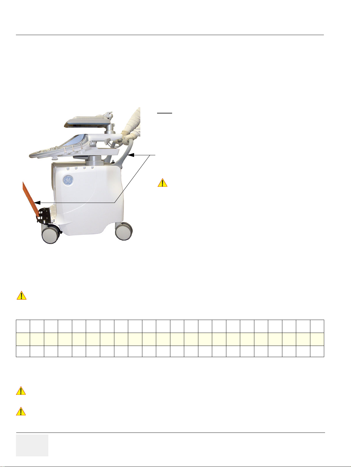
GE HEALTHCARERAFT VOLUSON E8 / VOLUSON E6
CAUTION
WARNINGWARNING
WARNINGWARNING
How to lift/move the system:
1. Remove the footrest cover: Turn the 2 quick release devices
below the footrest 90° (see: Figure 8-17 on page 8-16).
2. Pass a strap through the openings in the metal sheet.
3. Lift the system by the strap and the systems rear handle.
WARNING
CAUTION
DO NOT pull or lift the system with the front handle of the user
interface (control panel).
Always use a strap to lift the system.
DO NOT grasp the metal sheet with your hands.
Move the system forward or backward when going up or down
inclines. DO NOT move the system sideways or diagonally.
Note:
For important safety considerations refer to
Section 1-3-3 "Mechanical Safety" on page 1-11
D
IRECTION KTD102576, REVISION 7 DRAFT (AUGUST 23, 2012) SERVICE MANUAL
3-2-2 Installation Warnings
1.) Since the Voluson E8 / Voluson E6 weighs approximately 130 kg (286. 6 lbs. ) with out pe rip h er als ,
two people are required to unpack it.
2.) There are no operator serviceable components. To prevent shock, do not remove any covers or
panels. Should problems or malfunctions occur, unplug the power cord.
Only qualified service personnel should carry out servicing and troubleshooting.
3-2-2-1 Moving/Lifting the System
Figure 3-1 moving or lifting the system
3-2-2-2 System Acclimation Time
After being transported, the Voluson E8 / Voluson E6 system may be very cold or hot.
It requires one hour for each 2.5°C increment if it's temperature is below 10°C or above 40°C.
Equipment damage possibility. Turning the system on without acclimation after arriving at site
!! CAUTION:
may cause the system to be damaged.
Table 3-2 Acclimation Time
60 55 50 45 40 35 30 25 20 15 10 5 0 -5 -10 -15 -20 -25 -30 -35 -40
°C
140 131 122 113 104 96 86 77 68 59 50 41 32 23 14 5 -4 -13 -22 -31 -40
°F
864200000002468101214161820
hrs
3-2-2-3 Control Panel Position
If weight is placed on the Control Panel (UI) in it’s extended position the console could tip over.
The system should NOT be moved with the Control Panel (UI) extended. Move the
!! WARNING:
Control Panel to it’s centered and locked position. Refer to Section 6-5 on page 6-7.
Monitor mounting mechanism may break if not properly supported (e.g., with packing
!! WARNING:
foam) during transportation.
3-2 Section 3-2 - Set Up Reminders
Page 69
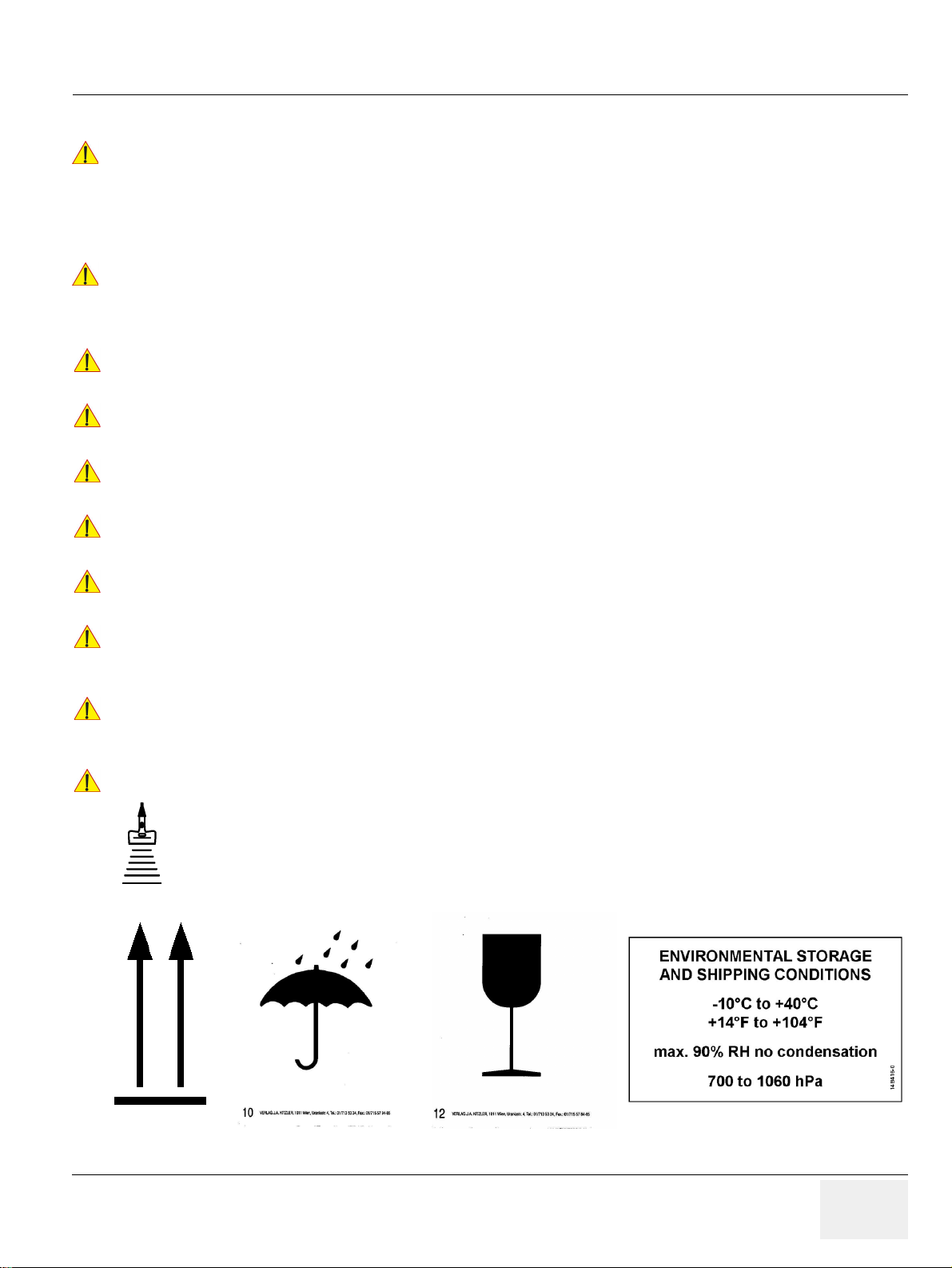
GE HEALTHCAREDRAFT VOLUSON E8 / VOLUSON E6
WARNINGWARNING
DANGER
CAUTION
CAUTION
CAUTION
CAUTION
CAUTION
CAUTION
CAUTION
CAUTION
D
IRECTION KTD102576, REVISION 7 DRAFT (AUGUST 23, 2012) SERVICE MANUAL
3-2-2-4 Brake Pedal Operation
REMEMBER: If the front wheel brakes are engaged for transportation, release brake
!! WARNING:
pedals (brakes on front wheels under the foot rest) to disengage the lock.
3-2-3 Safety Reminders
WHEN USING ANY TEST INSTRUMENT THAT IS CAPABLE OF OPENING THE
!! DANGER:
AC GROUND LINE (I.E., METER’S GROUND SWITCH IS OPEN), DO NOT
TOUCH THE SYSTEM!
Two people should unpack the system because of its weight.
!! CAUTION:
!! CAUTION:
!! CAUTION:
!! CAUTION:
Two people are required whenever a part weighing 16kg (35 lb.) or more must be lifted.
If the system is very cold or hot, do NOT turn on its power until it has had sufficient time to
acclimate to its operating environment.
To prevent electrical shock, connect the system to a properly grounded power outlet.
DO NOT use a three to two prong adapter. This defeats safety grounding.
DO NOT wear the ESD wrist strap when you work on live circuits and more than 30 V peak is
present.
!! CAUTION:
!! CAUTION:
!! CAUTION:
!! CAUTION:
DO NOT use a 20 Amp to 15 Amp adapter on the 120 Vac system’s power cord.
This system requires a dedicated 16 A circuit.
DO NOT operate this system unless all board covers and frame panels are securely in place,
to ensure optimal system performance and cooling.
(When covers are removed, EMI may be present).
OPERATOR MANUAL(S)
The User Manual(s) should be fully read and understood before operating the Voluson E8 /
Voluson E6. Keep manuals near the system for reference.
ACOUSTIC OUTPUT HAZARD
Although the ultrasound energy transmitted from the Voluson E8 / Voluson E6 ultrasound
system is within FDA limitations, avoid unnecessary exposure.
Ultrasound energy can produce heat and mechanical damage.
Figure 3-2 Environmental Labels
Chapter 3 - Setup Instructions 3-3
Page 70
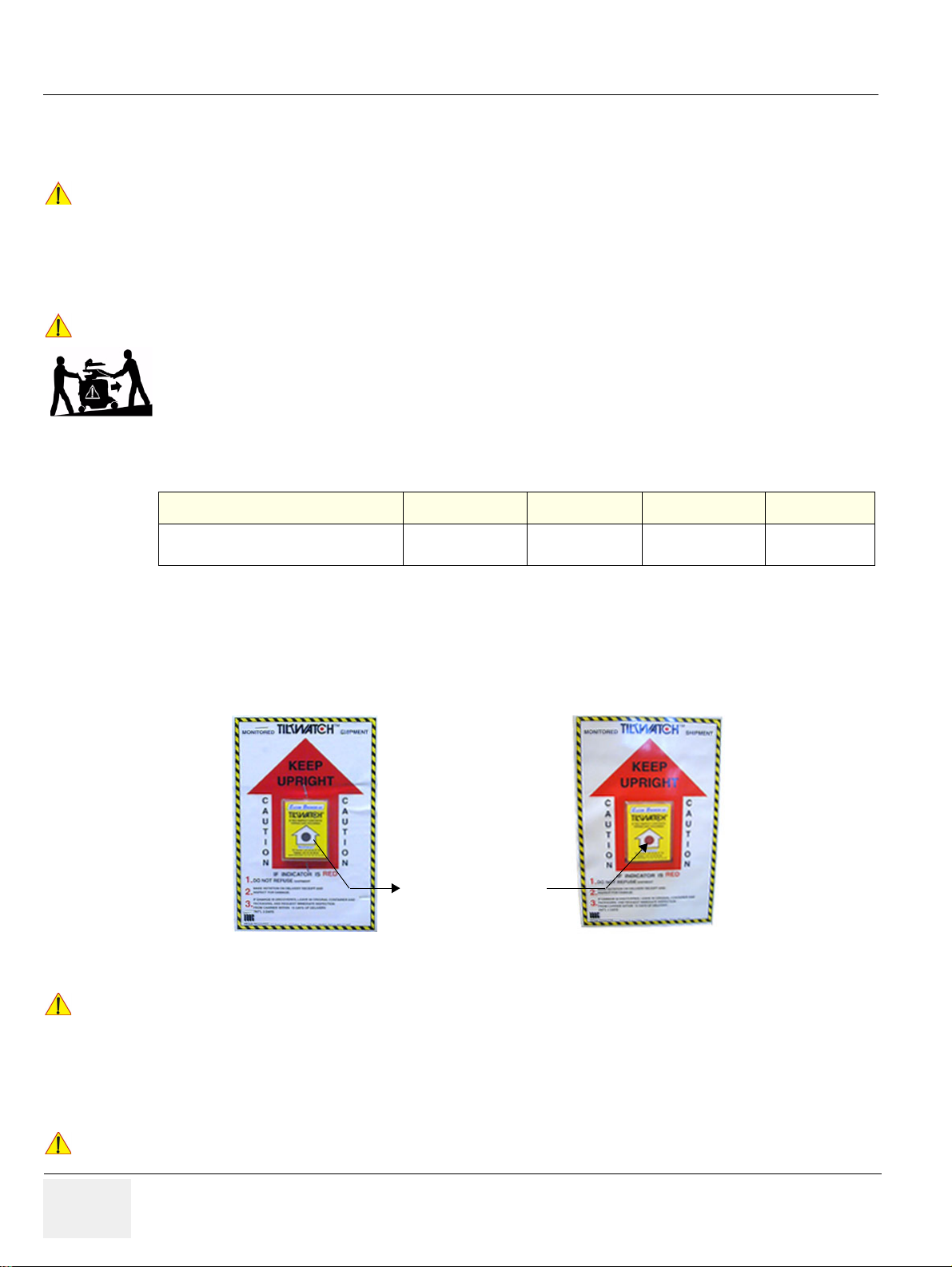
GE HEALTHCARERAFT VOLUSON E8 / VOLUSON E6
CAUTION
CAUTION
NOTICE
NOTICE
Indicator turns Red
D
IRECTION KTD102576, REVISION 7 DRAFT (AUGUST 23, 2012) SERVICE MANUAL
Section 3-3
Receiving and Unpacking the Equipment
Please read this section carefully before unpacking the Voluson E8 / Voluson E6 ultrasound
!! CAUTION:
!! CAUTION:
system and its (optional) peripherals.
The Voluson E8 / Voluson E6 ultrasound system, together with peripherals, probes and accessories are
shipped from the factory in a single durable shipping crate which is mounted on a raised wooden
platform base.
Transport only with forklift or stacker truck.
During transport pay attention to the point of gravity (“tilt and drop” indicator)!
Have two people available to unpack the Voluson E8 / Voluson E6.
Attempts to move the system considerable distances (or on an incline) by one person alone,
could result in personal injury, and/or damage to the system.
Table 3-3 Shipping Carton - Dimensions and Weight
Description Height Width Depth
Voluson E8 / Voluson E6
incl. peripherals and accessories
* Weight is approximate and will vary depending upon the supplied peripherals
1490 mm / 58.6 inch 780 mm / 30.7 inch 1180 mm / 46.5 inch 196 kg / 432 lbs
Weight*
Before unpacking the system:
• Inspect the crate for visible damage.
• Inspect the Drop and Tilt Indicator for evidence of accidental shock or tilting during transit (damage
incident, see: Figure 3-3 below).
Figure 3-3 Drop and Tilt Indicator
The device must only be transported in the original packaging!
!! NOTICE:
Each shipping crate is sealed with cross-head screws. A Phillips 2 screwdriver is needed to open it.
It is recommended to keep and store the shipping crate and all other packing materials (including the
support foams, anti-static plastic cover, etc.), in case the system has to be moved to a different location.
Unpack the devices such a way that packaging can be reused.
For warranty purposes, storage of the above is required for one year from date of purchase.
If the shipping crate is damaged, please inform the GE Healthcare sales representative immediately.
!! NOTICE:
3-4 Section 3-3 - Receiving and Unpacking the Equipment
Page 71
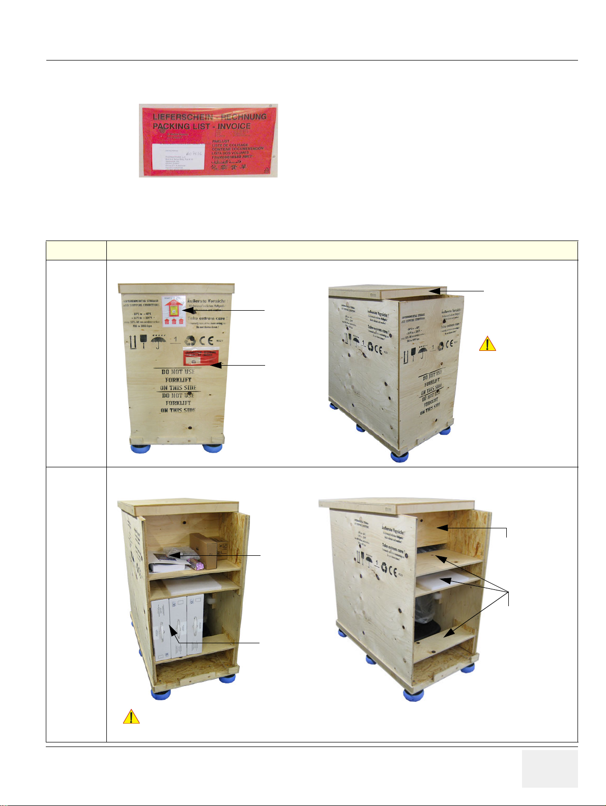
GE HEALTHCAREDRAFT VOLUSON E8 / VOLUSON E6
Check whether delivery is complete
(according to packing list) and check visual damage!
The envelope with delivery address, packing list and
invoice is located on the front panel of the crate.
tilt and drop
indicator
envelope with
packing list
place the top panel
on the crate
(middle of side walls)
CAUTION
!! CAUTION:
DO NOT remove
the top panel.
CAUTION
!! CAUTION:
probes
DO NOT open side panels prior to removing the front panel!
Accessories could drop down and DAMAGE the user interface!
accessories
for accessories
wooden racks
horizontal
finally remove
vertical board
D
IRECTION KTD102576, REVISION 7 DRAFT (AUGUST 23, 2012) SERVICE MANUAL
Section 3-3 Receiving and Unpacking the Equipment (cont’d)
Figure 3-4 envelope at front panel of the crate
Table 3-4 Unpacking Procedure
Step Task
1.
Loosen the screws. DO NOT remove the top panel, just place it on the crate (about middle of side walls).
2.
Take off the front panel, then remove probes and accessories from the wooden box.
Afterwards pull out all the horizontal wooden racks for accessories, finally remove also the vertical board.
Chapter 3 - Setup Instructions 3-5
Page 72
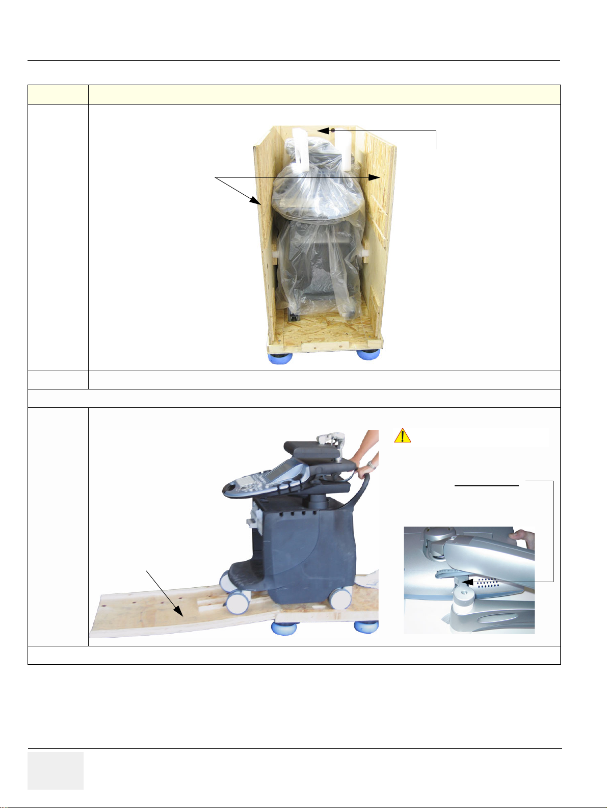
GE HEALTHCARERAFT VOLUSON E8 / VOLUSON E6
remove side walls
finally remove rear panel
(used for the ramp)
rear panel
is used for ramp
(bottom side up)
NOTICE
!! NOTICE:
THE SYSTEM IS LOWERED TO ITS
MINIMUM HEIGHT, WITH MONITOR
FLAPPED AND LOCKED DOWN.
T
HE CONTROL CONSOLE IS
CENTERED AND LOCKED IN POSITION.
D
IRECTION KTD102576, REVISION 7 DRAFT (AUGUST 23, 2012) SERVICE MANUAL
Table 3-4 Unpacking Procedure
Step Task
3.
Remove the left and right side walls, finally remove also the rear panel of the crate; the rear panel is used for the ramp.
4.
Caution: Two people are needed in the next step due to the weight of the equipment.
5.
Note: Packing crate and material should be stored for future use.
Carefully remove foam packing material and plastic bag from the ultrasound system and monitor.
Disengage the brakes, grasp the system at the handle, then slowly move system down the ramp (bottom side of the rear panel).
3-6 Section 3-3 - Receiving and Unpacking the Equipment
Page 73
GE HEALTHCAREDRAFT VOLUSON E8 / VOLUSON E6
NOTICE
b
D
IRECTION KTD102576, REVISION 7 DRAFT (AUGUST 23, 2012) SERVICE MANUAL
Section 3-4
Preparing for Set Up
3-4-1 Verify Customer Order
1.) After unpacking the equipment, it is important to verify th at all items order ed by the cu stomer have
been received. Compare all items listed on the packing slip (delivery note) with those received.
It is recommended to keep and store the shipping carton and all other packing materials (includin g the
!! NOTICE:
Step Item Recommended Procedure
1
2
support foams, anti-static plastic cover, etc.), in case the system has to be moved to a different location.
Unpack the devices such a way that packaging can be reused.
For warranty purposes, storage of the above is required for one year from date of purchase.
2.) Visually inspect the system components using the following checklist.
Table 3-5 Damage Inspection Checklist - Voluson E8 / Voluson E6 System
Rating Plate Enter Serial Number: _________________________ (printed on rating plate, see: Figure 1-2 on page 1-14)
Console Verify that the system is switched OFF and unplugged. Clean the console and control panel.
3
Control Console
4
Probes
5
LCD Display
6
Fans Verify that the system’s cooling fans and peripheral fans are operating.
7
Rear Panel
8
Covers
9
Peripherals
10
Power Cord
System Voltage
11
setting
Physically inspect the control console for missing or damaged items.
After switching on the system, verify the proper illumination of all the control panel buttons.
Check all probes for wear and tear on the lens, cable, and connector. Look for bent or damaged pins on the
connector and in the connector socket on the system. Verify that the EMI fingers around the probe connector
socket housing are intact. Check the probe locking mechanism and probe switch.
Clean the LCD display by gently wiping with a dry, soft, lint-free non-abrasive folded cloth. Inspect the monitor
for scratches and raster burn.
Check the rear panel connectors for bent pins, loose connections and loose or missing hardware. Screw all
the cable connectors tightly to the connector sockets on the panel. Verify that the labeling is in good condition.
Check that all screws are tightly secured in place, that there are no dents or scratches and that no internal
parts are exposed.
Check and clean the peripherals in accordance with the manufacturer’s directions.
To prevent EMI or system overheating, dress the peripheral cables inside the peripheral cover.
Check the power cord for cuts, loose hardware, tire marks, exposed insulation, or any deterioration.
Verify continuity. Replace the power cord, as required.
Verify that the Voluson E8 / Voluson E6 ultrasound system is set to the correct voltage.
see: Section 3-4-2 "System Voltage Settings" on page 3-8
NOTE: Report any items that are missing, back-ordered, or damaged, to your GE Healthcare sales
representative. The contact address is shown in Contact Information on page 1-17.
Chapter 3 - Setup Instructions 3-7
Page 74

GE HEALTHCARERAFT VOLUSON E8 / VOLUSON E6
WARNINGWARNING
D
IRECTION KTD102576, REVISION 7 DRAFT (AUGUST 23, 2012) SERVICE MANUAL
3-4-2 System Voltage Settings
Verify that the scanner is set to the correct voltage. The Voltage setting for the Voluson E8 / Voluson
E6 Scanner is found on the identification plate (see: Figure 1-2 o n page 1-14) on the rear of the system.
CONNECTING A Voluson E8 / Voluson E6 SCANNER TO THE WRONG VOLTAGE
!! WARNING:
LEVEL WILL MOST LIKELY DESTROY THE SCANNER.
3-4-3 EMI Protection
This system has been designed to minimize the effects of Elec to-Magnetic Interference (EMI). Many of
the covers, shields, and screws are provided primarily to protect the system from image artifacts caused
by this interference. For this reason, it is imperative that all covers and hardware are installed and
secured before the system is put into operation.
Ensure that the system is protected from electromagnetic interference (EMI), as follows:
• Operate the system at least 15 feet away from equipment that emits strong electromagnetic
radiation.
• Operate the system in an area enclosed by walls, floors and ceilings comprised of wood, plaster or
concrete, which help prevent EMI.
• Shield the system when operating it in the vicinity of radio broadcast equipment, if necessary.
• Do not operate mobile phones or other EMI emitting devices in the ultrasound room.
• Verify that all EMI rules listed in the following table are follow e d :
The Voluson E8 / Voluson E6
environmentally qualified facilities, in terms of the prevention of radio wave interference. Operation of
the ultrasound system
in an inappropriate environment can cause electronic in terference to radios and
television sets situated near the medical equipment.
For further details and EMI Prevention/Abatement refer to Section 2-2-3 "EMI Limitations" on page 2-4.
ultrasound system is approved for use in hospitals, clinics and other
3-8 Section 3- 4 - Preparing for Set Up
Page 75
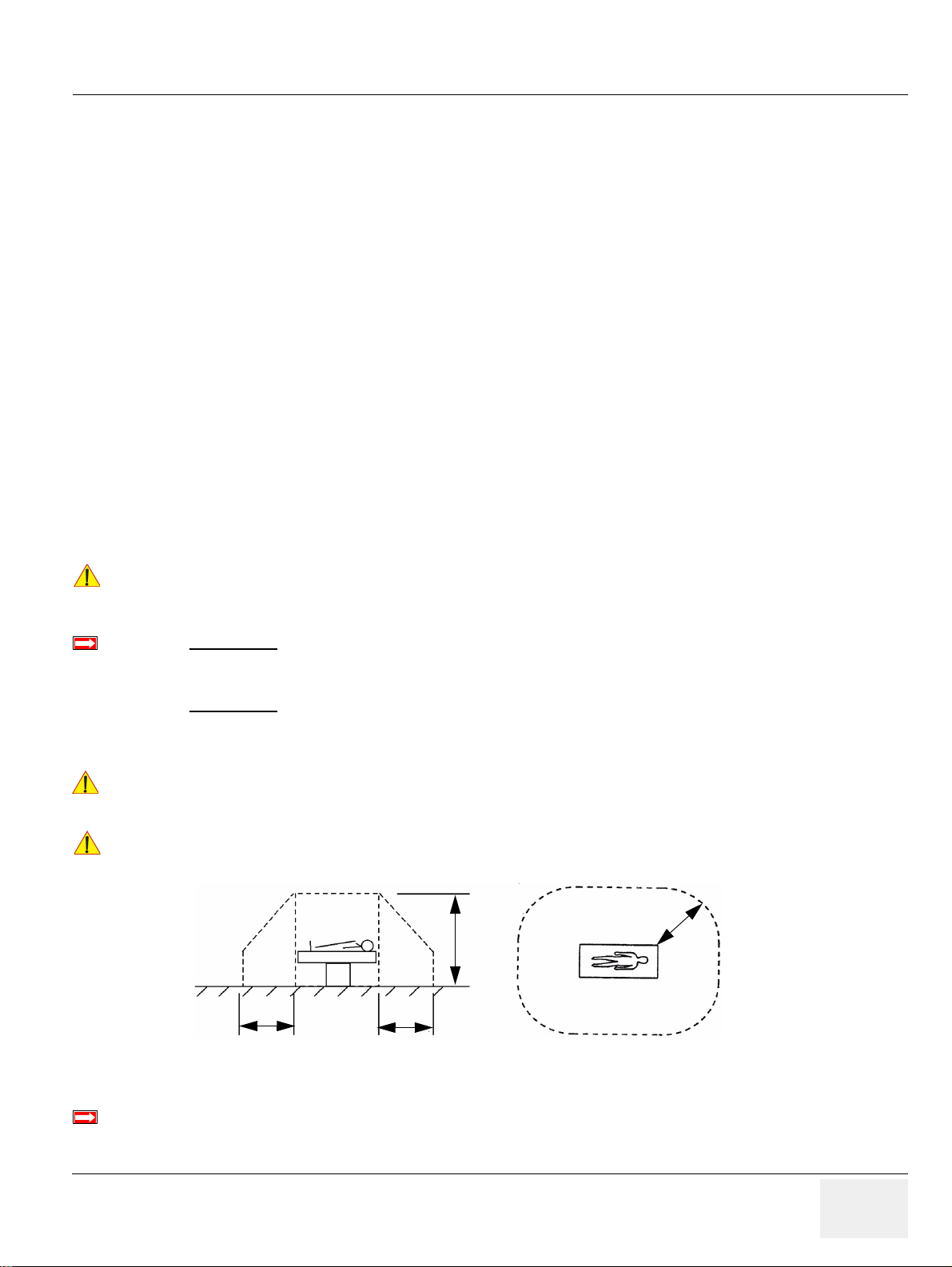
GE HEALTHCAREDRAFT VOLUSON E8 / VOLUSON E6
NOTICE
BT Version:
WARNINGWARNING
CAUTION
BT Version:
2,5 m
1,5 m
1,5 m1,5 m
D
IRECTION KTD102576, REVISION 7 DRAFT (AUGUST 23, 2012) SERVICE MANUAL
Section 3-5
Connection of Auxiliary Devices
Hardware installation procedures described in the sub-sections:
3-5-1 Connecting the LCD Monitor . . . . . . . . . . . . . . . . . . . . . . . . . . . . . . . . . . . . . . . . . . . . . 3-10
3-5-2 Connecting the Black & White Printer. . . . . . . . . . . . . . . . . . . . . . . . . . . . . . . . . . . . . . . 3-11
3-5-3 Connecting the Color Printer . . . . . . . . . . . . . . . . . . . . . . . . . . . . . . . . . . . . . . . . . . . . . 3-13
3-5-4 Connecting the DeskJet Color Printer . . . . . . . . . . . . . . . . . . . . . . . . . . . . . . . . . . . . . . 3-15
3-5-5 Connecting the DVD Recorder. . . . . . . . . . . . . . . . . . . . . . . . . . . . . . . . . . . . . . . . . . . . 3-16
3-5-6 Connecting the Wireless Network Adapter. . . . . . . . . . . . . . . . . . . . . . . . . . . . . . . . . . . 3-22
3-5-7 Connecting the VGA Image (Video) Resizer . . . . . . . . . . . . . . . . . . . . . . . . . . . . . . . . . 3-23
3-5-8 Connecting the 19” LCD Secondary “Patient” Monitor . . . . . . . . . . . . . . . . . . . . . . . . . . 3-25
3-5-9 Connecting the Footswitch . . . . . . . . . . . . . . . . . . . . . . . . . . . . . . . . . . . . . . . . . . . . . . . 3-27
3-5-10 Connecting the ECG-preamplifier. . . . . . . . . . . . . . . . . . . . . . . . . . . . . . . . . . . . . . . . . . 3-28
3-5-11 Connecting the USB Flash Memory Stick. . . . . . . . . . . . . . . . . . . . . . . . . . . . . . . . . . . . 3-29
3-5-12 Connecting the external USB Hard disk (Handydrive) . . . . . . . . . . . . . . . . . . . . . . . . . . 3-29
3-5-13 General Remarks and Hints when using external USB-Devices . . . . . . . . . . . . . . . . . . 3-30
NOTE: Always observe the instructions given in the manual of the peripheral/auxiliary device.
It is impossible to attach a Black&White printer, a Color printer and a DVD recorder in the console at
!! NOTICE:
the same time, as there is not enough space for them all.
At the left shelf you can place either a Color printer or a DVD recorder.
BT09/BT10:
Only one recording device - DVD Recorder or VCR (VideoCa ssette Recorder) - can be connected at a
time to the Voluson E8 / Voluson E6.
BT12/
BT13:
Only one recording device (either the optional “built-in” DVR-Drive or a standard VCR/DVD Recorder)
can be connected at a time to the Voluson® E6 / Voluson® E8 system. Not both together!
After each installation, the leakage currents have to be measured according to
!! WARNING:
!! CAUTION:
IEC 60601-1 respectively UL 60601-1.
Please observe that some printers may not be medical devices! If the Bluetooth Printer and/or
Line Printers are not medical devices, they have to be located outside of the patient
environment (according to IEC 60601-1 / UL 60601-1).
BT-Version:
NOTE: For more detailed Safety Considerations when connecting auxiliary devices to the Voluson E8 / Voluson
E6 system, please review: Chapter 1 - Auxiliary Devices Safety, on page 1-12.
The main outlet for auxiliary devices on Back of the Console (see: Table 3-55 on page 3-55) is not
available at systems with BT10/BT12/BT13 hardware version
(or, if the main harness has been replaced).
Chapter 3 - Setup Instructions 3-9
Page 76
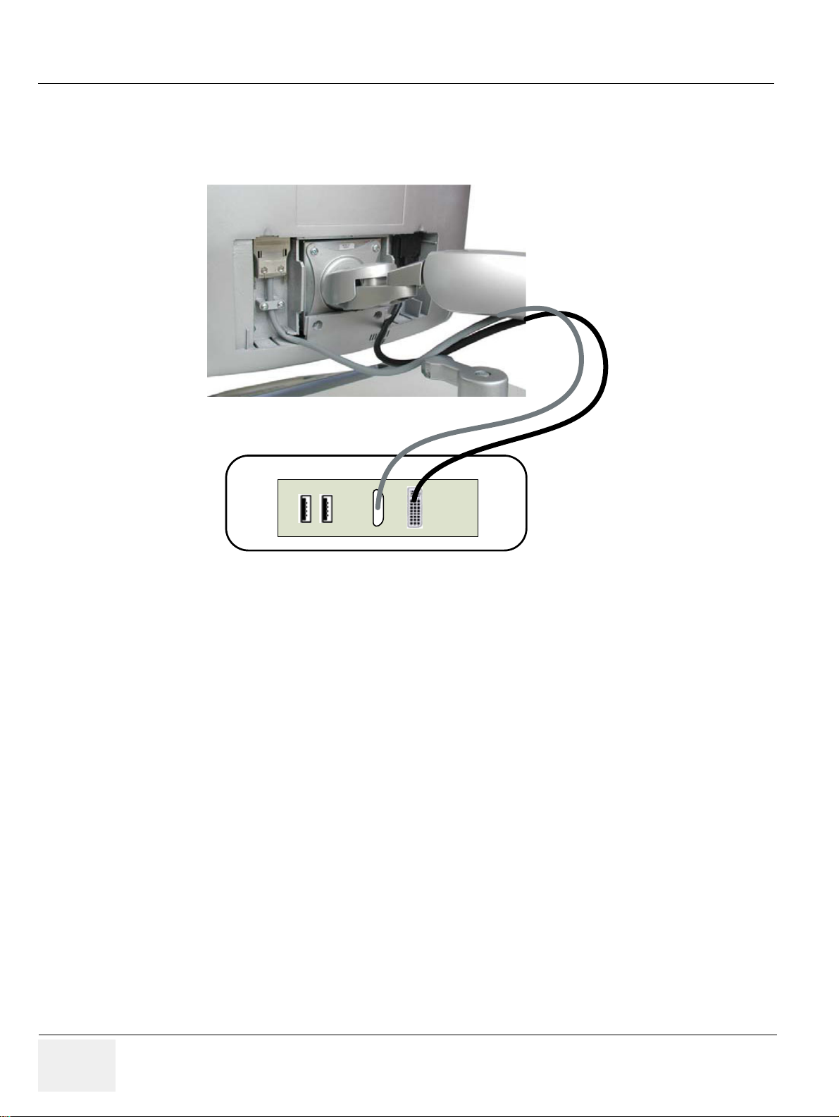
GE HEALTHCARERAFT VOLUSON E8 / VOLUSON E6
Console back
D
IRECTION KTD102576, REVISION 7 DRAFT (AUGUST 23, 2012) SERVICE MANUAL
3-5-1 Connecting the LCD Monitor
NOTE: The LCD monitor comes pre-installed with the system.
Figure 3-5 Connection Scheme - LCD Monitor
3-10 Section 3-5 - Connection of Auxiliary Devices
Page 77
GE HEALTHCAREDRAFT VOLUSON E8 / VOLUSON E6
Please
Note
WARNINGWARNING
D
IRECTION KTD102576, REVISION 7 DRAFT (AUGUST 23, 2012) SERVICE MANUAL
3-5-2 Connecting the Black & White Printer
1.) Power OFF/Shutdown the system as described in: Section 3-6-3 on page 3-34.
2.) Connect the Black & White printer according to connection scheme, see: Figure 3-6 on p age 3-12.
NOTE: The B&W printer should be connected to the USB3 port of the Voluson E8 / Voluson E6´s PC-part.
Location of the USB3 port depends on the installed PC-Motherboard.
3.) When all the cables are connected, press the Power ON switch on the Black & White printer.
4.) Power ON/Boot up the Voluson E8 / Voluson E6 system as described in Section 3-6-2 on page 3-
31. All software drivers are pre-installed for the designated Black & White printer only.
If the printer driver for the Mitsubishi P95D B&W printer is not pre-installed, install it manually by means
of the “Found New Hardware Wizard” and the printer dr iver disk which is included with this new printer.
5.) After physical connection to the Voluson E8 / Voluson E6 system, assign the printer to a remote key
(P1
, P2, P3 and/or P4) as described in Section 3-7-5 "Remote Control Selection" on page 3-48.
6.) Verify the correct settings in the printer “Properties”, see: Section 3-7-4 "Adjustment of Printer
Settings" on page 3-41.
!! WARNING:
After each installation, the leakage currents have to be measured according to
IEC 60601-1 respectively UL 60601-1.
Chapter 3 - Setup Instructions 3-11
Page 78
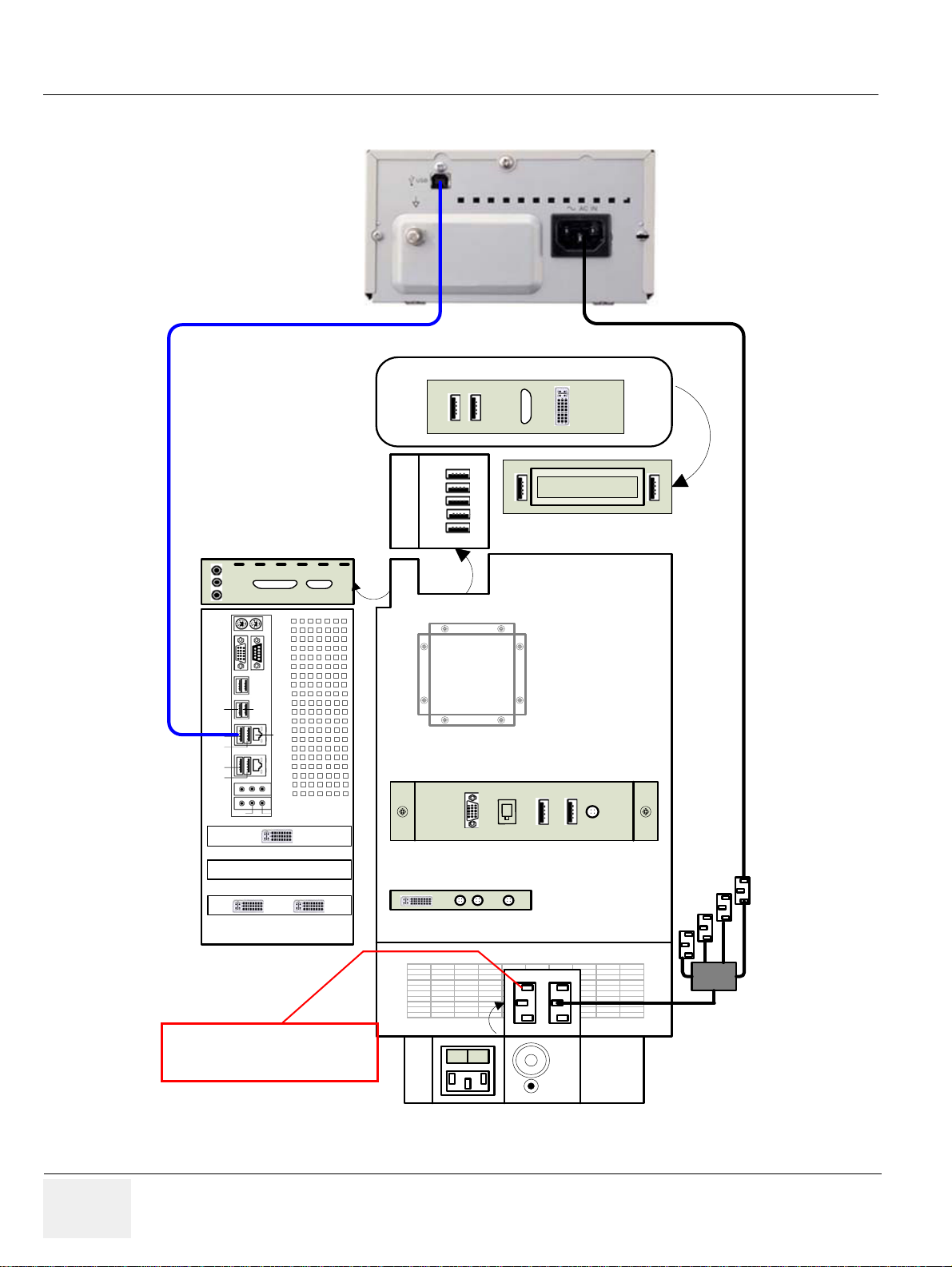
GE HEALTHCARERAFT VOLUSON E8 / VOLUSON E6
Lift
Aux
Lift is only used for the lifter
(230V - can not be changed)
Black & White Printer
(e.g., Sony UP-D897)
D
IRECTION KTD102576, REVISION 7 DRAFT (AUGUST 23, 2012) SERVICE MANUAL
3-5-2-1 Connection Scheme: B&W Printer
Line
PC
USB
USB 3
USB 4
USB 5
USB 6
Audio
RS232
UI
Line Out
to USB3
In
Out
Mic
UI-Top
USB Hub
Top
Line In
LAN
ECG
Console back
A
BC
DE
text
DVD Writer
DVI Out
S - Video
DVI - In
Monitor
DVI - Out
Figure 3-6 B&W Printer connection
3-12 Section 3-5 - Connection of Auxiliary Devices
Out InOut
I
O
Page 79
GE HEALTHCAREDRAFT VOLUSON E8 / VOLUSON E6
Please
Note
WARNINGWARNING
D
IRECTION KTD102576, REVISION 7 DRAFT (AUGUST 23, 2012) SERVICE MANUAL
3-5-3 Connecting the Color Printer
1.) Power OFF/Shutdown the system as described in: Section 3-6-3 on page 3-34.
2.) Connect the Color printer according to connection scheme, see: Figure 3-7 on page 3-14
NOTE: The Color printer should be connec te d to th e USB4 port of th e Volu so n E8 / Voluson E6´s PC-part.
Location of the USB4 port depends on the installed PC-Motherboard.
3.) When all the cables are connected, press the Power ON switch on the Color printer.
4.) Power ON/Boot up the Voluson E8 / Voluson E6 system as described in Section 3-6-2 on page 3-
31. All software drivers are pre-installed for the designated Co lor printer only.
If the printer driver for the Sony UP-D25MD or Mitsubi shi CP30D color printer is not pre-installed, install
it manually by means of the “Found New Hardware Wizard” and the printer driver disk which is included
with this new printer.
5.) After physical connection to the Voluson E8 / Voluson E6 system, assign the printer to a remote key
(P1
, P2, P3 and/or P4) as described in Section 3-7-5 "Remote Control Selection" on page 3-48.
6.) Verify the correct settings in the printer “Properties”, see: Section 3-7-4 "Adjustment of Printer
Settings" on page 3-41.
!! WARNING:
After each installation, the leakage currents have to be measured according to
IEC 60601-1 respectively UL 60601-1.
Chapter 3 - Setup Instructions 3-13
Page 80
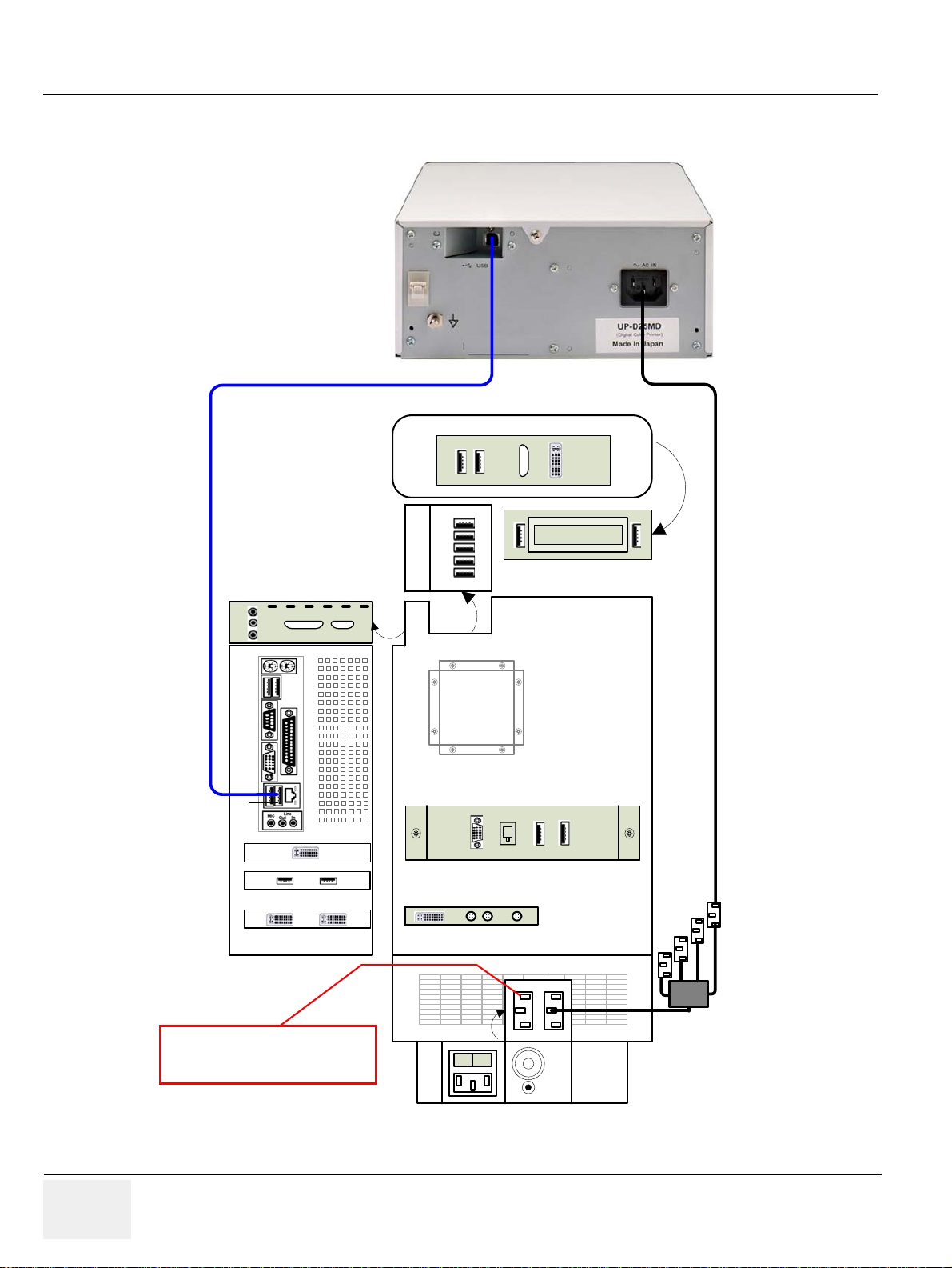
GE HEALTHCARERAFT VOLUSON E8 / VOLUSON E6
Lift
Aux
Lift is only used for the lifter
(230V - can not be changed)
Color Printer
(e.g., Sony UP-D25MD)
D
IRECTION KTD102576, REVISION 7 DRAFT (AUGUST 23, 2012) SERVICE MANUAL
3-5-3-1 Connection Scheme: Color Printer
to USB4
Console back
A
BC
DE
text
DVD Writer
In
Line
Out
Mic
PC
USBUIUSB Hub
Top
RS232
Out
USB3
USB4
Audio
USB5 USB6
DVI - In
UI-Top
DVI Out
LAN
ECG
Monitor
DVI - Out
I
S - Video
Out InOut
O
Figure 3-7 Color Printer connection
3-14 Section 3-5 - Connection of Auxiliary Devices
Page 81
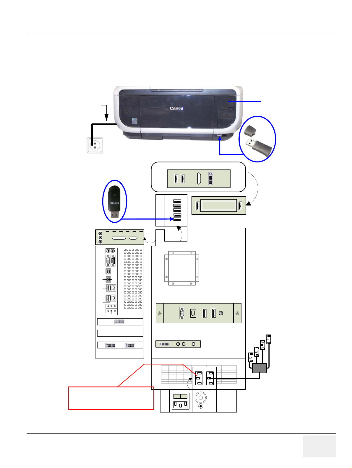
GE HEALTHCAREDRAFT VOLUSON E8 / VOLUSON E6
text
Console back
DVD Writer
I
O
UI-Top
ECG
S - Video
Out InOut
DVI - Out
Mic
Line
Out
In
A
BC
DE
PC
DVI Out
DVI - In Monitor
RS232
USBUIUSB Hub
Top
LAN
USB 3
USB 4
USB 5
USB 6
Audio
Line Out
Line In
PC
Lift
Aux
Lift is only used for the lifter
(230V - can not be changed)
USB Bluetooth Adapter
connected to USB port E
Power Cable
connected to the rear side
Bluetooth
Printer Adapter
of the Canon printer
DeskJet Color Printer
(e.g., Canon Pixma MP610)
D
IRECTION KTD102576, REVISION 7 DRAFT (AUGUST 23, 2012) SERVICE MANUAL
3-5-4 Connecting the DeskJet Color Printer
3-5-4-1 Connection via Bluetooth Adapter
The DeskJet Color Printer can be connected to an externa l, non-isola ted power sour ce. The bluetoo th
adapter should be directly connected to the indicated USB port E on the RTB Distribution Board Botto m.
Figure 3-8 DeskJet Color Printer connection (via Bluetooth Adapter)
Chapter 3 - Setup Instructions 3-15
Page 82
GE HEALTHCARERAFT VOLUSON E8 / VOLUSON E6
CAUTION
CAUTION
NOTICE
BT Version:
NOTICE
WARNINGWARNING
D
IRECTION KTD102576, REVISION 7 DRAFT (AUGUST 23, 2012) SERVICE MANUAL
3-5-4-1 Connection via Bluetooth Adapter (cont’d)
Please observe that the complete Bluetooth Printer Assembly has to be located outside of the
!! CAUTION:
patient environment (according to IEC 60601-1 / UL 60601-1).
The printer being used may not be a medical device. The Bluetooth Printer Set and the Power
!! CAUTION:
Supply of the Bluetooth Printer Adapter is also not a medical device.
The equipment meets the requirements of the EN 60950 Standard.
Please use the proper Bluetooth Printer Connection set.
!! NOTICE:
see: Chapter 9 - Printers, on page 9-31.
3-5-5 Connecting the DVD Recorder
At BT12 (SW12.x.x) and BT13 (EC200, 13.x.x) systems , the common recording device is the optional
“built-in” DVR drive (instead of the “normal” DVD drive).
The Sony DVO-1000MD DVD recorder is only able to read and write on DVD+RW (ReWriteable)
!! NOTICE:
media! Please check on your DVD case before using.
1.) Power OFF/Shutdown the system as described in: Section 3-6-3 on page 3-34.
2.) Connect the DVD Recorder according to connection scheme, see: Figure 3-9 on page 3-17.
NOTE: The DVD recorder should be connected to the USB port A of the RTB Distribution board inside the
Voluson E8 / Voluson E6.
3.) When all power and signal cables are connected to the system and recorder, proceed as follows:
a.) Press the power ON switch on the DVD recorder.
b.) Turn ON the power of the Voluson E8 / Voluson E6 system.
4.) After physical connection to the Voluson E8 / Voluson E6 system:
a.) Adjust the DVD Recorder settings as described in Section 3-5-5-2 on page 3-18.
b.) Check and if necessary change the Video Norm, see: Section 3-8-1-6 on page 3-52.
c.) Check and if necessary change the Recorder Type, see: Section 3-8-1-7 on page 3-52.
d.) Assign the recorder control to a remote key P1
, P2, P3 and/or P4 as described in
Section 3-7-5 "Remote Control Selection" on page 3-48.
After each installation, the leakage currents have to be measured according to
!! WARNING:
IEC 60601-1 respectively UL 60601-1.
3-16 Section 3-5 - Connection of Auxiliary Devices
Page 83
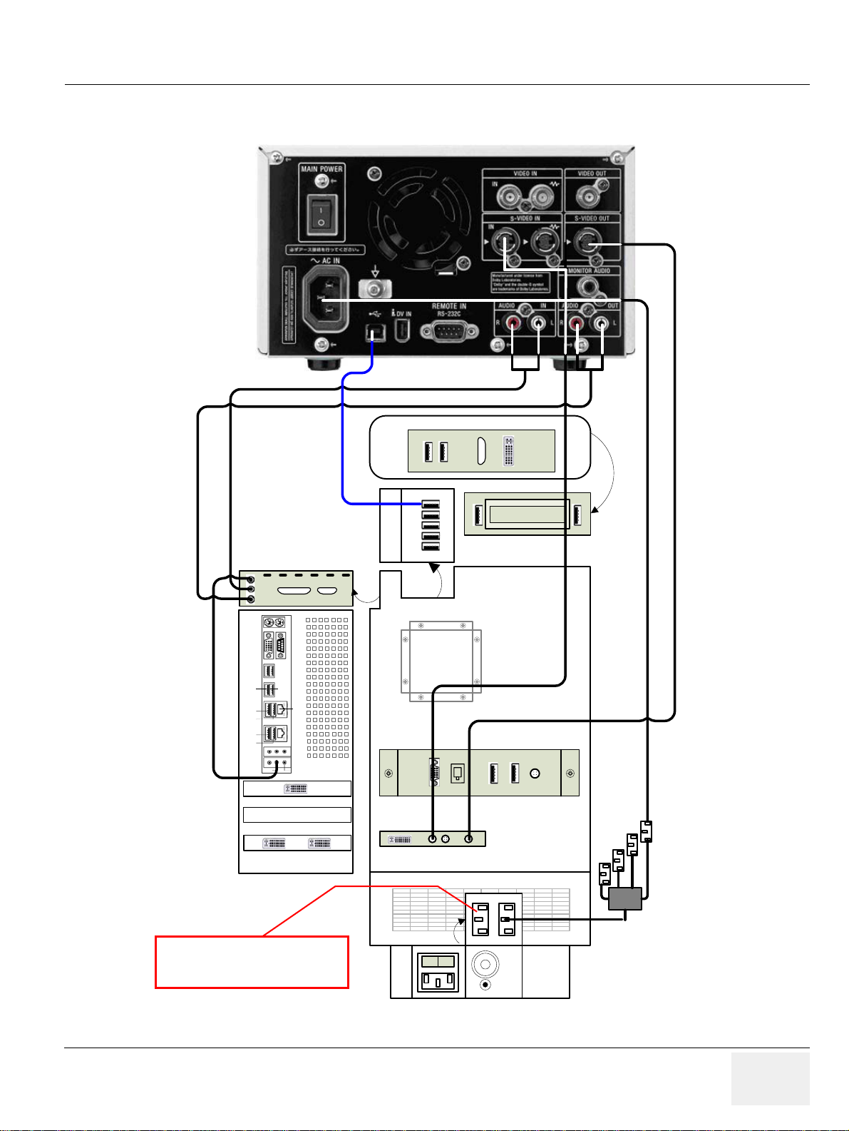
GE HEALTHCAREDRAFT VOLUSON E8 / VOLUSON E6
Lift
Aux
Lift is only used for the lifter
(230V - can not be changed)
D
IRECTION KTD102576, REVISION 7 DRAFT (AUGUST 23, 2012) SERVICE MANUAL
3-5-5-1 Connection Scheme: DVD Recorder
Console back
In
Line
Out
UI-Top
Mic
PC
RS232
USBUIUSB Hub
Top
USB 3
USB 4
USB 5
USB 6
Audio
Line Out
DVI Out
DVI - In Monitor
LAN
Line In
ECG
to USB port A
DVI - Out
A
BC
DE
S - Video
Out InOut
text
DVD Writer
I
O
Figure 3-9 DVD Recorder connection
Chapter 3 - Setup Instructions 3-17
Page 84
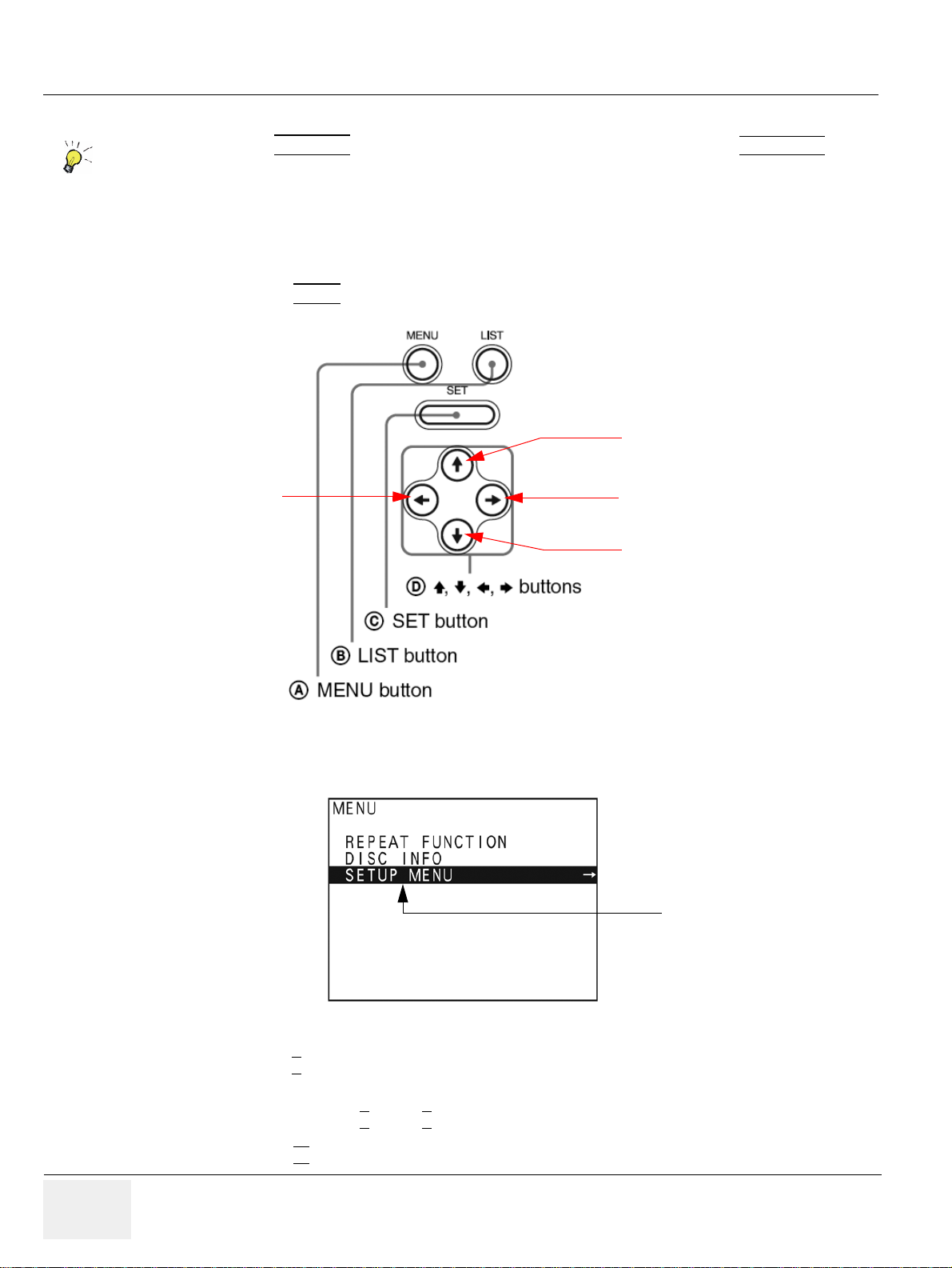
GE HEALTHCARERAFT VOLUSON E8 / VOLUSON E6
Please
Note
Up
Down
Right
Left
select [SETUP MENU]
D
IRECTION KTD102576, REVISION 7 DRAFT (AUGUST 23, 2012) SERVICE MANUAL
3-5-5-2 Adjustment of the DVD Recorder Settings
If you press the UTILITIES key on the Voluson E8 / Voluson E6 console and then EXT.VIDEO,
you will see the actual screens (as shown here in this manual).
You can use the on-screen programming menu's instead of the LCD to setup the DVD recorder.
This ensures that all cables have been properly connected first!
3-5-5-2-1 Changing the Remote Interface to USB
1.) If not already done, switch on the Sony DVO-1000MD DVD recorder.
2.) Press the MENU
button (A) located on the front of the DVD recorder see Figure 3-10 below.
Figure 3-10 Keys on the front of the recorder
3.) The “Main Menu” appears on the LCD screen of the DVD recorder, see: Figure 3-11 below.
Figure 3-11 “Main Menu” - [SETUP MENU] highlighted
4.) Press the ↓
(down) button on the front of the recorder repeatedly until the [SETUP MENU] item
is highlighted.
NOTE: Each time you press the
5.) Press the →
↑
(up) or ↓ (down) button, the highlight cursor moves up/down item by item.
(right) button. The “Setup Menu” appears.
3-18 Section 3-5 - Connection of Auxiliary Devices
Page 85
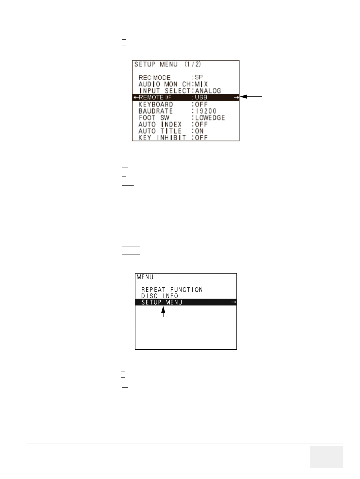
GE HEALTHCAREDRAFT VOLUSON E8 / VOLUSON E6
change REMOTE I/F
to USB
select [SETUP MENU]
D
IRECTION KTD102576, REVISION 7 DRAFT (AUGUST 23, 2012) SERVICE MANUAL
6.) Press the ↓ (down) button on the front of the recorder repeatedly until [REMOTE I/F] is
highlighted, see Figure 3-14 on page 3-20.
Figure 3-12 “Main Menu” - [REMOTE I/F] highlighted
7.) Press the →
8.) Press the ↓
9.) Press the SET
(right) button to enter the REMOTE I/F menu.
(down) button until you see USB on the screen.
button (C) - on the front of the DVD recorder - to select USB.
Your DVD recorder is now using USB Remote Interface.
3-5-5-2-2 Changing TV System (Video Format)
NOTE: To check Video format needed, see: Table 3-6, “TV-System and Region Code,” on page 3-21.
1.) If not already done, switch on the Sony DVO-1000MD DVD recorder.
2.) Press the MENU
button (A) located on the front of the DVD, see: Figure 3-10 on page 3-18.
3.) The “Main Menu” appears on the LCD screen of the DVD recorder, see: Figure 3-13 below.
Figure 3-13 “Main Menu” - [SETUP MENU] highlighted
4.) Press the ↓
is highlighted.
5.) Press the →
(down) button on the front of the recorder repeatedly until the [SET UP MENU] item
(right) button. The “Setup Menu” appears, see Figure 3-14 on page 3-20.
Chapter 3 - Setup Instructions 3-19
Page 86
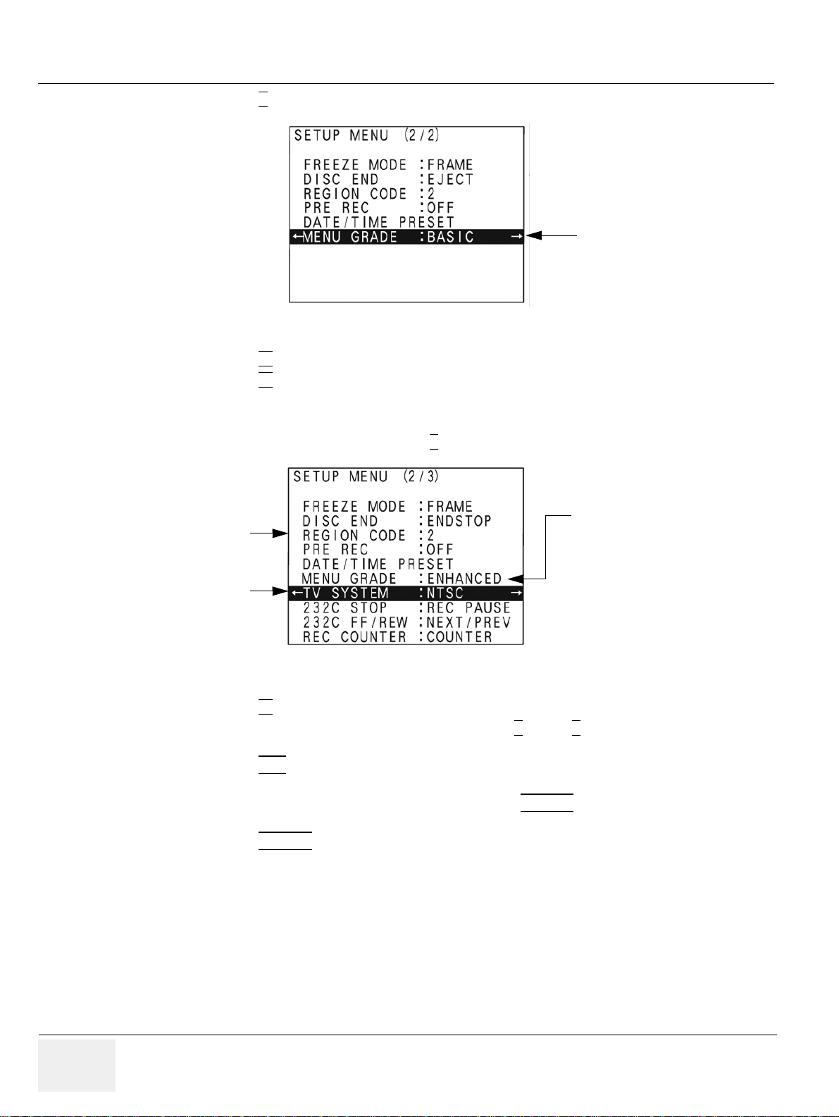
GE HEALTHCARERAFT VOLUSON E8 / VOLUSON E6
change MENU GRADE
to ENHANCED
Menu Grade: ENHANCED
TV SYSTEM
REGION CODE
D
IRECTION KTD102576, REVISION 7 DRAFT (AUGUST 23, 2012) SERVICE MANUAL
6.) Press the ↓ (down) button repeatedly, until [MENU GRADE] is highlighted .
Figure 3-14 “Setup Menu” - [MENU GRADE] highlighted
7.) Press the →
8.) Press the ←
(right) button and select [ENHANCED].
(left) button, to exit the “Menu Grade” menu.
NOTE: Now additional items (see: Figure 3-15 on page 3-20) are displayed in the “Setup Menu”.
9.) Select [TV SYSTEM] by pressing the ↓
(down) button.
Figure 3-15 “Setup Menu” - [TV SYSTEM] highlighted
10.)Press the →
11.)Select the appropriate video signal by pressing the ↑
(right) button. The “TV System” Sub menu appears.
(up) or ↓ (down) button respectively.
To check the video signal, see: Table 3-6, “TV-System and Region Code,” on page 3-21.
12.)Press the SET
button (C).
The message “Now loading...” appears and the system starts to save the settings.
13.)When “Power off” appears on the display, press the POWER
switch on the front of the DVD
recorder to turn power off.
14.)Press the POWER
switch again to turn power on.
3-20 Section 3-5 - Connection of Auxiliary Devices
Page 87
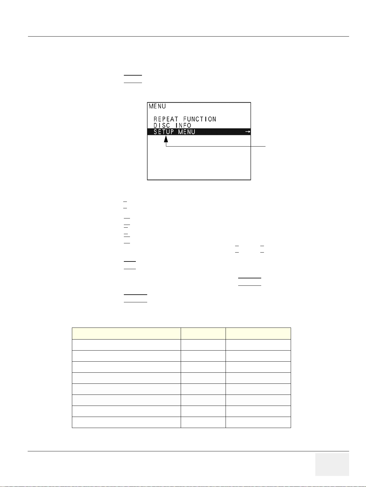
GE HEALTHCAREDRAFT VOLUSON E8 / VOLUSON E6
select [SETUP MENU]
D
IRECTION KTD102576, REVISION 7 DRAFT (AUGUST 23, 2012) SERVICE MANUAL
3-5-5-2-3 Change the Region Code
NOTE: To specify the correct region code, see: Table 3-6, “TV-System and Region Code,” on page 3-21.
1.) If not already done, switch on the Sony DVO-1000MD DVD recorder.
2.) Press the MENU
button (A) located on the front of the DVD, see: Figure 3-10 on page 3-18.
3.) The “Main Menu” appears on the LCD screen of the DVD recorder, see: Figure 3-16 below.
Figure 3-16 “Main Menu” - [SETUP MENU] highlighted
4.) Press the ↓
(down) button on the front of the recorder repeatedly until the [SET UP MENU] item
is highlighted.
5.) Press the →
6.) Press the ↓
7.) Press the →
(right) button. The “Setup Menu” appears, see Figure 3-15 on page 3-20.
(down) button repeatedly, until [REGION COD E] is highlighted.
(right) button. The “Region Code Menu” appears.
8.) Select the appropriate region code by pressing the ↑
To check the region code, see: Table 3-6, “TV-System and Region Code,” on page 3-21.
9.) Press the SET
button (C).
The message “Now loading...” appears and the system starts to save the settings.
10.)When “Power off” appears on the display, press the POWER
recorder to turn power off.
11.)Press the POWER
switch again to turn power on.
Table 3-6 TV-System and Region Code
Country Region Code TV-System
USA and Canada
Western Europe, Middle East, South Africa
Japan
Southeast Asia, incl. Hong Kong
Central and South America, Australia
Africa
Eastern Europe, Russia, Central Asia incl. India
China
1NTSC
2 PAL
2NTSC
3 PAL/NTSC
4 PAL
5 NTSC
5 PAL
6 PAL
(up) or ↓ (down) button respectively.
switch on the front of the DVD
Chapter 3 - Setup Instructions 3-21
Page 88
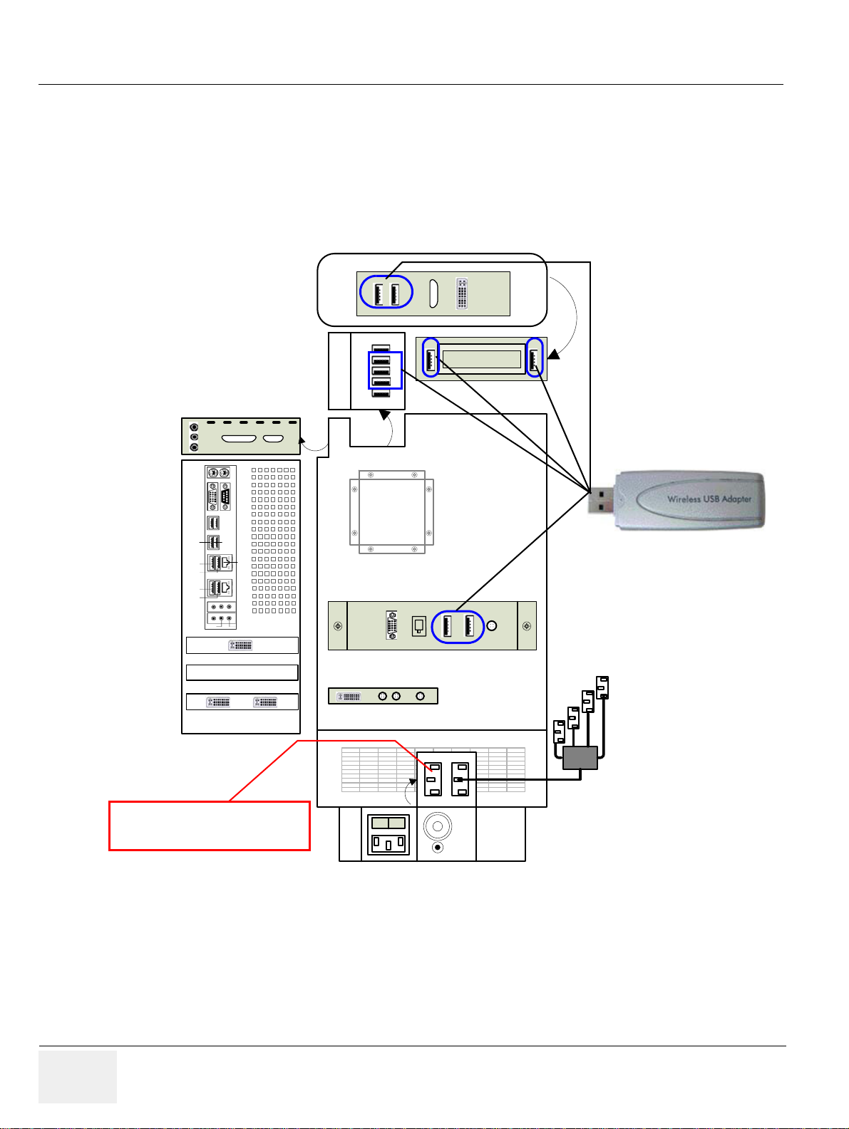
GE HEALTHCARERAFT VOLUSON E8 / VOLUSON E6
Lift is only used for the lifter
(230V - can not be changed)
D
IRECTION KTD102576, REVISION 7 DRAFT (AUGUST 23, 2012) SERVICE MANUAL
3-5-6 Connecting the Wireless Network Adapter
1.) Turn ON the power of the system and wait till the system has booted.
2.) Plug the Wireless Network adapter into an accessible USB port of the Voluson E8 / Voluson E6.
All software drivers are pre-installed for the designated Wireless Network adapter only.
The Wireless Network Adapter can be connected to any accessible USB port of the Voluson E8 /
Voluson E6.
Console back
A
PC
BC
DE
In
Line
Out
Mic
RS232
UI-Top
ECG
text
DVD Writer
USBUIUSB Hub
Top
USB 3
USB 4
USB 5
USB 6
Audio
Line Out
LAN
Line In
DVI Out
DVI - In Monitor
DVI - Out
S - Video
Out InOut
I
O
Figure 3-17 Connection Scheme - Wireless (USB) Network Adapter
NOTE: Connection of the WLAN Adapter is always the same
(no differences between PC-Motherboard and/or BT-version of the system).
NOTE: After physical connection of the WLAN adapter to the Voluson E8 / Voluson E6 system, follow the
procedure described in Section 3-11-2 "Wireless Network Configuration" on page 3-62.
3-22 Section 3-5 - Connection of Auxiliary Devices
Page 89
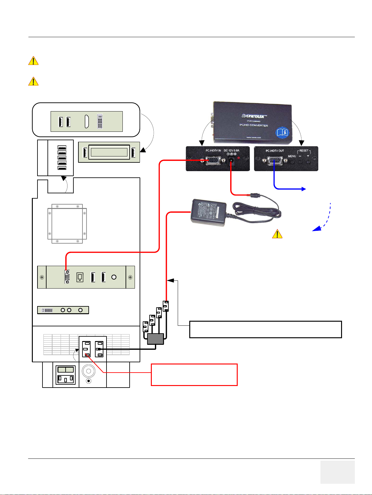
GE HEALTHCAREDRAFT VOLUSON E8 / VOLUSON E6
NOTICE
NOTICE
Power Supply
VGA Image
to Secondary
“Patient” Monitor
Lift is only used for the lifter
(230V - can not be changed)
CAUTION
!! CAUTION:
A Secondary “Patient” Monitor MUST NEVER be connected to
the Voluson E6 / Voluson E8 systems mains supply directly!
Always connect it to an appropriate Isolation Transformer
(see: Chapter 9 - Optional Equipment, on page 9-33)
Resizer box
Connect the power supply of the VGA Image Resizer to the
power cable plug behind the door on the right side cover.
D
IRECTION KTD102576, REVISION 7 DRAFT (AUGUST 23, 2012) SERVICE MANUAL
3-5-7 Connecting the VGA Image (Video) Resizer
For more detailed description, how to replace/mount the VGA Image Resizer, refer to:
!! NOTICE:
!! NOTICE:
Console back
Chapter 8 - Replacing optional Peripherals / How to mount Peripherals at a later date, on page 8-25.
The VGA Image (Video) Resizer is required whenever the used Secondary “Patient” Monitor has a
different screen resolution than the Voluson E8 / Voluson E6 system!
A
BC
DE
text
DVD Writer
DVI - Out
S - Video
Out InOut
I
O
Figure 3-18 Connection Scheme - VGA Image Resizer
NOTE: After physical connection of the VGA Image Resizer to the Voluson system, follow the procedure
described in Section 3-5-7-1 "Adjustment of the VGA Image Resizer Settings " on page 3-24 .
Chapter 3 - Setup Instructions 3-23
Page 90
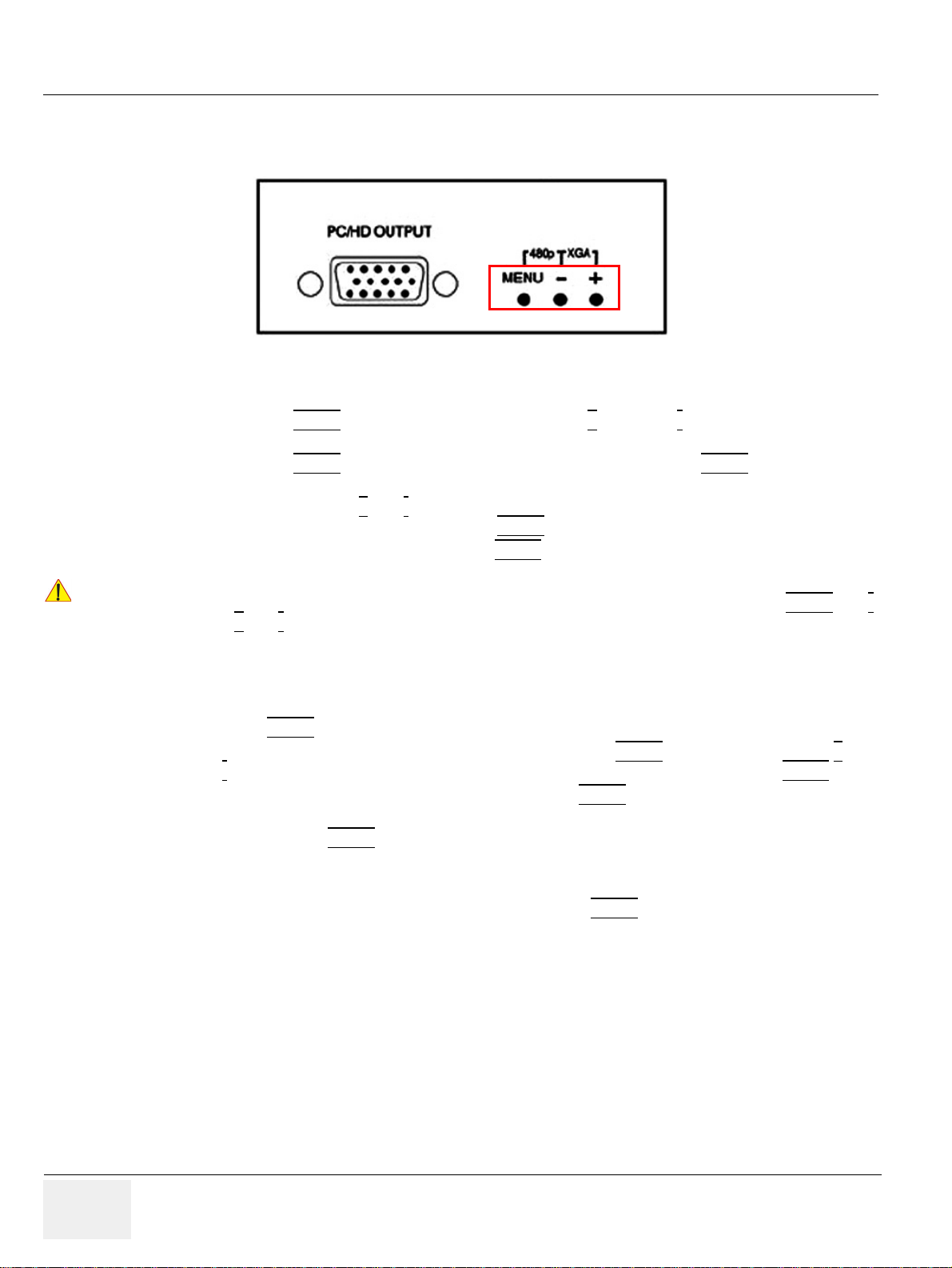
GE HEALTHCARERAFT VOLUSON E8 / VOLUSON E6
NOTICE
D
IRECTION KTD102576, REVISION 7 DRAFT (AUGUST 23, 2012) SERVICE MANUAL
3-5-7-1 Adjustment of the VGA Image Resizer Settings
To get the best results in image quality out of this Resizer Box you should make the following settings.
Figure 3-19 keys on Image Resizer
1.) Set the output resolution of the Image Resizer to the native resolution of the monitor:
!! NOTICE:
a.) Press the MENU
key at the Image Resizer and use + (plus) and - (minus) key to navigate to
Output Setup using the On Screen Menu.
b.) Press the MENU
key to enter the sub menu output setup, press the MENU key again to
highlight the Mode Setting.
c.) Choose mode with +
When correct mode is displayed press MENU
d.) Navigate to menu item Exit and press MENU
and - key.
key to activate the setting.
key to leave the On Screen Menu.
Changes get effective immediately. If monitor is not showing anything after a change, your setting might
be wrong. To reset the Image Resizer in case th at an ythi ng we nt wrong, p re ss eith er the MENU
key or the +
and - key until the image reappears. Try other settings that are supp orted by your monitor.
2.) Use high quality Video cables especially for longer distances. High quality cables improve overall
image quality due to lower sensitivity on electromagnetic interferences.
3.) Set Brightness & Contrast for best and detailed image display.
a.) Press MENU
b.) Select first item Cont. (means contrast) by pressing the MENU
-
key) until you think you get the best result on your monitor and then press the MENU key.
c.) Na vig at e to Bright. (means brightness) and press MENU
key, select Picture Adj. using the On Screen Menu.
key and adjust it (using + and
key again to highlight item.
d.) Set brightness to any value you think it results in the best quality image for your monitor and
then press the MENU
key.
NOTE: You may change the Color setting in the same way if you think adjustment is necessary.
and -
e.) When everything is done, navigate to Exit and press MENU
3-24 Section 3-5 - Connection of Auxiliary Devices
key to leave the On Screen Menu.
Page 91

GE HEALTHCAREDRAFT VOLUSON E8 / VOLUSON E6
CAUTION
NOTICE
NOTICE
NOTICE
D
IRECTION KTD102576, REVISION 7 DRAFT (AUGUST 23, 2012) SERVICE MANUAL
3-5-8 Connecting the 19” LCD Secondary “Patient” Monitor
The 19” LCD Secondary “Patient” Monitor MUST NEVER be connected to the Voluson E8 /
!! CAUTION:
!! NOTICE:
!! NOTICE:
!! NOTICE:
Voluson E6 ultrasound systems mains supply directly!
Always connect it to the supplied Isolation Transformer!
The Secondary Monitor is the only item to be connected to the Transformer.
The 19” LCD Secondary Monitor is NOT intended for diagnostic use.
It is an additional device used to allow the patient to watch the proceedings.
Take your time to think about the best position of the monitor in your facilities.
Patients should be able to view the monitor easily and without having to bend or turn around.
DO NOT connect the 19” LCD Secondary Monitor to the Voluson E8 / Voluson E6 via USB cable.
Use the supplied VGA cable.
For more detailed description, how to replace/mount the 19” LCD Second ary “Patient” Monitor, refer to:
Chapter 8 - Replacing optional Peripherals / How to mount Peripherals at a later date, on page 8-25.
1.) Power OFF/Shutdown the system as described in: Section 3-6-3 on page 3-34.
2.) Connect the Secondary Monitor according to connection scheme (see: F i gure3-20 on page 3-26).
NOTE: Connection of the 19” LCD Secondary “Patient” Monitor is always the same
(no differences between PC-Motherboard and/or BT-version of the system).
Chapter 3 - Setup Instructions 3-25
Page 92
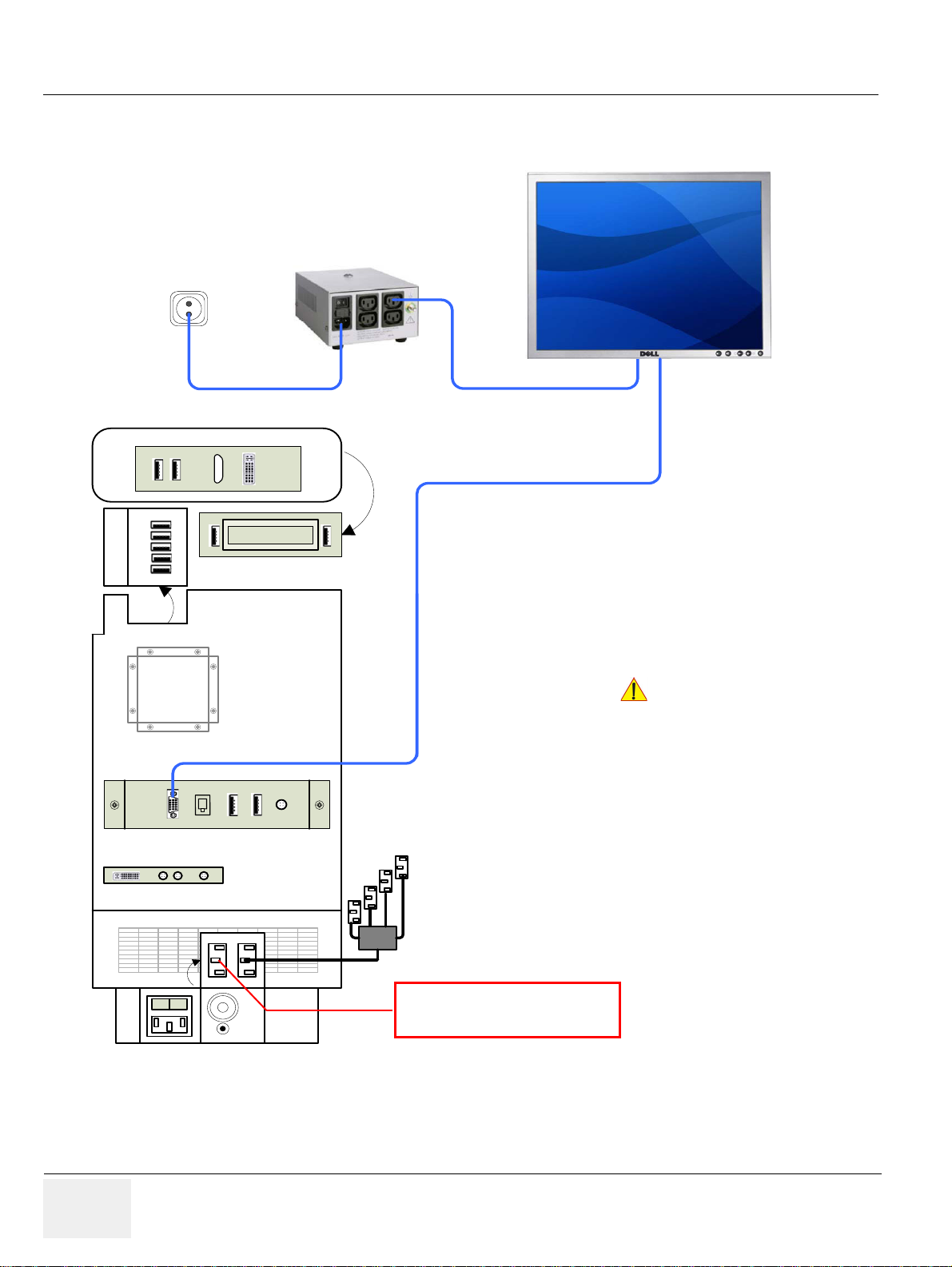
GE HEALTHCARERAFT VOLUSON E8 / VOLUSON E6
Lift is only used for the lifter
(230V - can not be changed)
19” LCD
Secondary Monitor
appropriate
VGA cable
connected to the
rear side of the
2nd Monitor
Transformer
A Secondary “Patient” Monitor MUST NEVER
be connected to the Voluson E8 / Voluson E6 ultrasound
systems mains supply directly!
Always connect it to an appropriate Isolation Transformer
(see: Chapter 9 - Optional Equipment, on page 9-33)
CAUTION
!! CAUTION:
D
IRECTION KTD102576, REVISION 7 DRAFT (AUGUST 23, 2012) SERVICE MANUAL
3-5-8 Connecting the 19” LCD Secondary “Patient” Monitor (cont’d)
Console back
A
BC
DE
text
DVD Writer
DVI - Out
S - Video
Out InOut
I
O
Figure 3-20 Connection Scheme - 19” Secondary LCD Monitor
3-26 Section 3-5 - Connection of Auxiliary Devices
Page 93
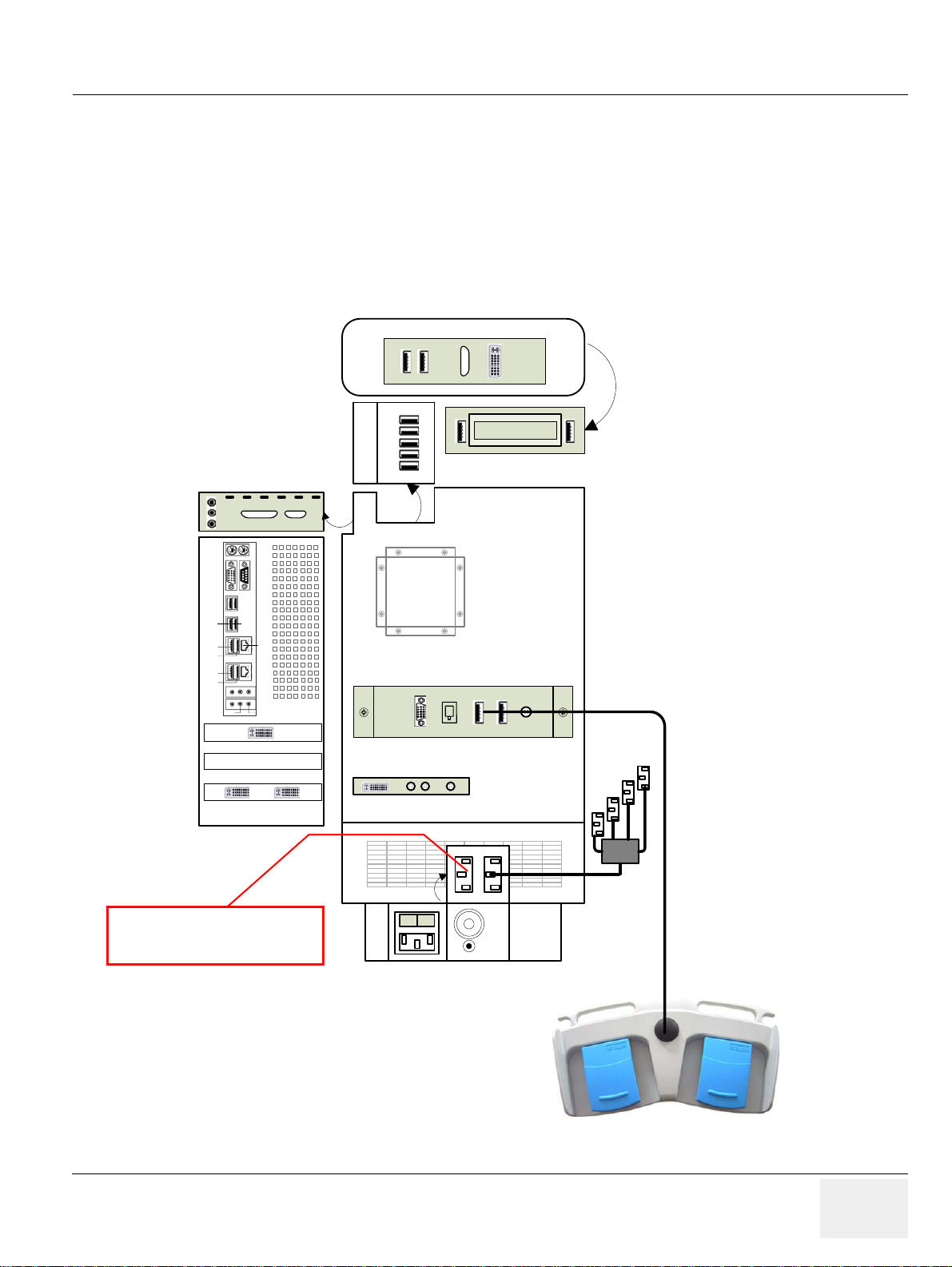
GE HEALTHCAREDRAFT VOLUSON E8 / VOLUSON E6
Lift
Aux
Lift is only used for the lifter
(230V - can not be changed)
D
IRECTION KTD102576, REVISION 7 DRAFT (AUGUST 23, 2012) SERVICE MANUAL
3-5-9 Connecting the Footswitch
The footswitch should be directly connected to any accessible USB-port on the Voluson E8 / Voluson
E6 (e.g., on rear of the system).
NOTE: Connection of the Footswitch is always the same
(no differences between PC-Motherboard and/or BT-version of the system).
After physical connection, adjust the Footswitch (Left/Right) as described in
Section 3-8-1-8 "How to adjust function of the Footswitch" on page 3-52.
Console back
A
PC
BC
DE
In
Line
Out
Mic
RS232
UI-Top
ECG
text
DVD Writer
USBUIUSB Hub
USB 3
USB 4
USB 5
USB 6
Audio
Line Out
DVI - In Monitor
Top
DVI Out
LAN
Line In
DVI - Out
S - Video
Out InOut
I
O
Figure 3-21 Connection Scheme - Footswitch
Chapter 3 - Setup Instructions 3-27
Page 94
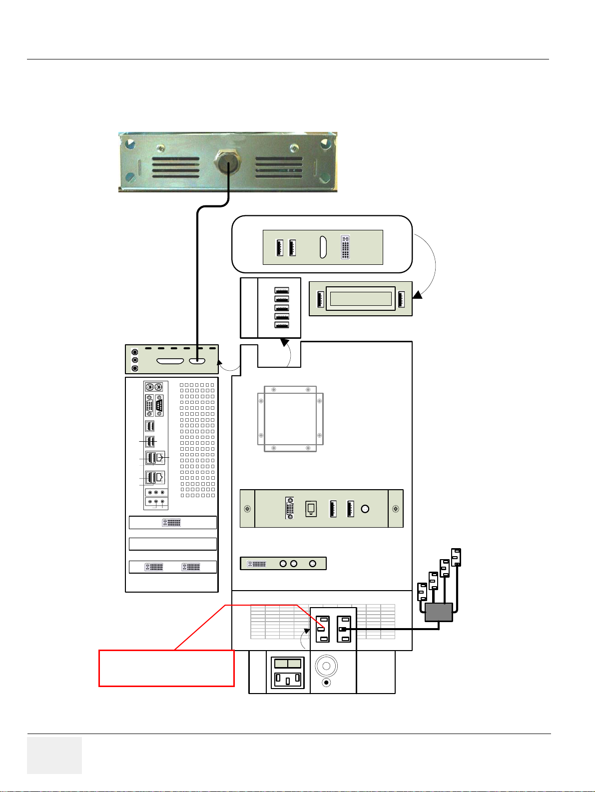
GE HEALTHCARERAFT VOLUSON E8 / VOLUSON E6
Lift
Aux
Lift is only used for the lifter
(230V - can not be changed)
D
IRECTION KTD102576, REVISION 7 DRAFT (AUGUST 23, 2012) SERVICE MANUAL
3-5-10 Connecting the ECG-preamplifier
NOTE: Connection of the ECG is always the same
(no differences between PC-Motherboard and/or BT-version of the system).
Console back
A
BC
DE
text
DVD Writer
In
Line
Out
UI-Top
Mic
PC
RS232
USBUIUSB Hub
Top
USB 3
USB 4
USB 5
USB 6
Audio
Line Out
Line In
DVI Out
DVI - In Monitor
LAN
ECG
DVI - Out
S - Video
Out InOut
I
O
Figure 3-22 Connection Scheme - ECG-preamplifier
3-28 Section 3-5 - Connection of Auxiliary Devices
Page 95

GE HEALTHCAREDRAFT VOLUSON E8 / VOLUSON E6
NOTICE
NOTICE
NOTICE
NOTICE
D
IRECTION KTD102576, REVISION 7 DRAFT (AUGUST 23, 2012) SERVICE MANUAL
3-5-11 Connecting the USB Flash Memory Stick
Before connecting an USB device, please read General Remarks and Hints when using external USB-
!! NOTICE:
Devices on page 3-30.
The USB Flash Memory Stick may be connected to an accessible USB port of the Voluson E8 / Voluson
E6 system (e.g., on back of control console).
An external USB Flash Memory Stick can be connected once the system is powered ON, or after
shutdown. The Voluson E8 / Voluson E6, Windows detects the device and automatically installs a
driver. During this process several dialogs may pop up, starting with the „Found New Hardware ” dialog.
NOTE: Memory drives or sticks may be sensitive to EMC interference.
This may affect system performance and/or image quality.
Before disconnecting an external USB-device (e.g., USB Stick), the system has to be informed about
!! NOTICE:
the removal of the device! For this purpose press the USB
button on the keyboard.
For further details refer to: Section 3-5-13-2 "External USB-Devices - Disconnection" on page 3-30.
3-5-12 Connecting the external USB Hard disk (Handydrive)
Before connecting an USB device, please read General Remarks and Hints when using external USB-
!! NOTICE:
Devices on page 3-30.
The external “Handydrive” HDD may be connected to an accessible USB port of the Voluson E8 /
Voluson E6 system (e.g., on back of control console).
An external USB Hard Disk Drive can be connected once the system is powered ON, or after shutdown.
The Voluson E8 / Voluson E6, Windows detects the device and automatically installs a driver. During
this process several dialogs may pop up, starting with the „Found New Hardware“ dialog.
NOTE: Memory drives or sticks may be sensitive to EMC interference.
This may affect system performance and/or image quality.
Before disconnecting an external USB-device (e.g., USB Hard disk), the system has to be informed
!! NOTICE:
about the removal of the device! For this purpose press the USB
For further details refer to: Section 3-5-13-2 "External USB-Devices - Disconnection" on page 3-30.
button on the keyboard.
Chapter 3 - Setup Instructions 3-29
Page 96
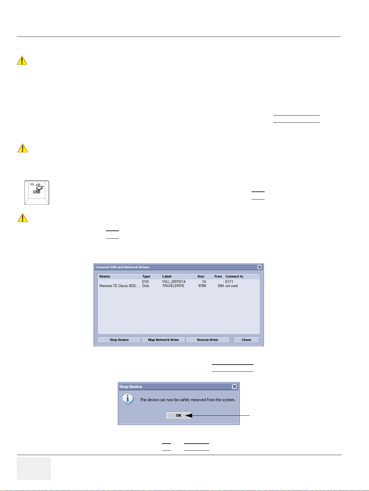
GE HEALTHCARERAFT VOLUSON E8 / VOLUSON E6
WARNINGWARNING
NOTICE
CAUTION
D
IRECTION KTD102576, REVISION 7 DRAFT (AUGUST 23, 2012) SERVICE MANUAL
3-5-13 General Remarks and Hints when using external USB-Devices
Do not connect or disconnect any external USB-devices to or from the system while
!! WARNING:
3-5-13-1 External USB-Devices - Connection
scanning a patient! The appearing dialogs could distract you from the scan!
When an external USB-storage device (such as a USB-memory stick or an external hard disk) is
connected to the Voluson E8 / Voluson E6, Windows detects the device and automatically installs a
driver. During this process, several dialogs may pop up, starting with th e “Found New Hardware “ dialog.
NOTE: If an external drive was not recognized automatically after connecting it, click RESCAN DRIVE
The device is then accessible using the drive letter the system assigned to it.
When connecting external USB devices, be sure to execute Safety Directions found in the
!! NOTICE:
Voluson E8 / Voluson E6 Basic User Manual.
3-5-13-2 External USB-Devices - Disconnection
Before an external USB-device (e.g., USB-memory stick) can be disconnected, the system has to be
informed about the removal of the device! For this purpose press the USB
button on the keyboard.
Unplugging or ejecting USB devices without first stopping them can often cause the system to
!! CAUTION:
crash and possibly result in loss of valuable data.
By pressing the USB
key on the keyboard, a dialog window (see: Figure 3-23 below) is displayed.
The “Connect USB and Network Drives” window shows all USB and Network drives connected to the
system. Using this dialog, the USB-devices can be stopped before they are physically disconnected.
.
Figure 3-23 Connect USB and Network Drives
To stop the external device, select it and then click the STO P DE VICE
Figure 3-24 Device can now be safely removed
Confirm the ‘Stop Device‘ dialog with OK
and CANCEL the “Connect USB and Network Drives” window.
3-30 Section 3-5 - Connection of Auxiliary Devices
button.
Page 97
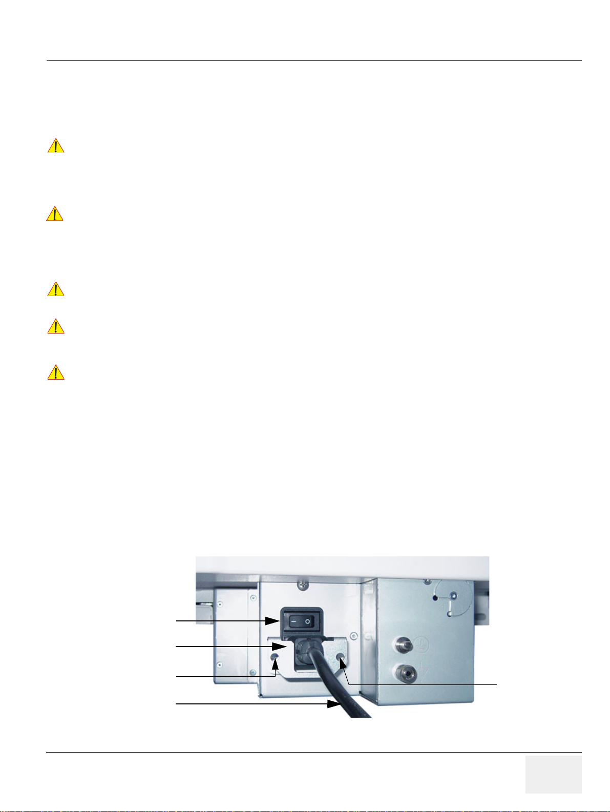
GE HEALTHCAREDRAFT VOLUSON E8 / VOLUSON E6
CAUTION
WARNINGWARNING
NOTICE
CAUTION
CAUTION
Circuit Breaker
Main Power Cable
pull-out protection
1 screw
1 screw
D
IRECTION KTD102576, REVISION 7 DRAFT (AUGUST 23, 2012) SERVICE MANUAL
Section 3-6
Completing the Set Up
3-6-1 Connecting the System to a Power Source
Prior to connect the Voluson system to a power source, verify compliance with all electrical and
!! CAUTION:
!! WARNING:
!! NOTICE:
!! CAUTION:
safety requirements. Check the power cord to verify that it is intact and of hospital-grade.
Products equipped with a power source (wall outlet) plug should be connected to the fixed
power socket that has a protective grounding conductor. Never use an adapter or converter to
connect with a power source plug (for example, a three-prong to two-prong converter).
The system’s power must be supplied from a separate, properly rated outlet to avoid
risk of fire. Refer to Section 2-2-2-1 "V oluson E8 / V oluson E6 Po wer Requirements" on
page 2-3 for rating information.
The power cord should not, under any circumstances, be altered to a configuration
rated less than that specified for the current.
Use only the power cords, cables and plugs provided by or designated by GE Healthcare to connect
the system to the power source.
Whenever disconnecting the Voluson system from the electrical outlet, always observe the
safety precautions. First unplug the main power cable from the wall outlet socket, then from the
system itself. Remove by pulling on the cable connector - DO NOT pull on the cable.
The Voluson E8 / Voluson E6 requires all covers!
!! CAUTION:
Operate this system only when all board covers and frame panels are securely in place.
The covers are required for safe operation, good system performance and cooling purposes.
3-6-2 Power On / Boot Up
3-6-2-1 Scanner Power On
1.) Connect the Main Power Cable to the back of the system.
2.) If not already done, screw on the pull-out protection of the mains power cable with the 2 screws.
3.) Connect the Main Power Cable to a hospital grade power outlet with the proper rated voltage.
Never use an adapter that would defeat the safety ground.
4.) Switch ON the Circuit Breaker at the rear of the system.
Figure 3-25 Circuit Breaker, pull-out protection and main power cable at rear of system
Chapter 3 - Setup Instructions 3-31
Page 98
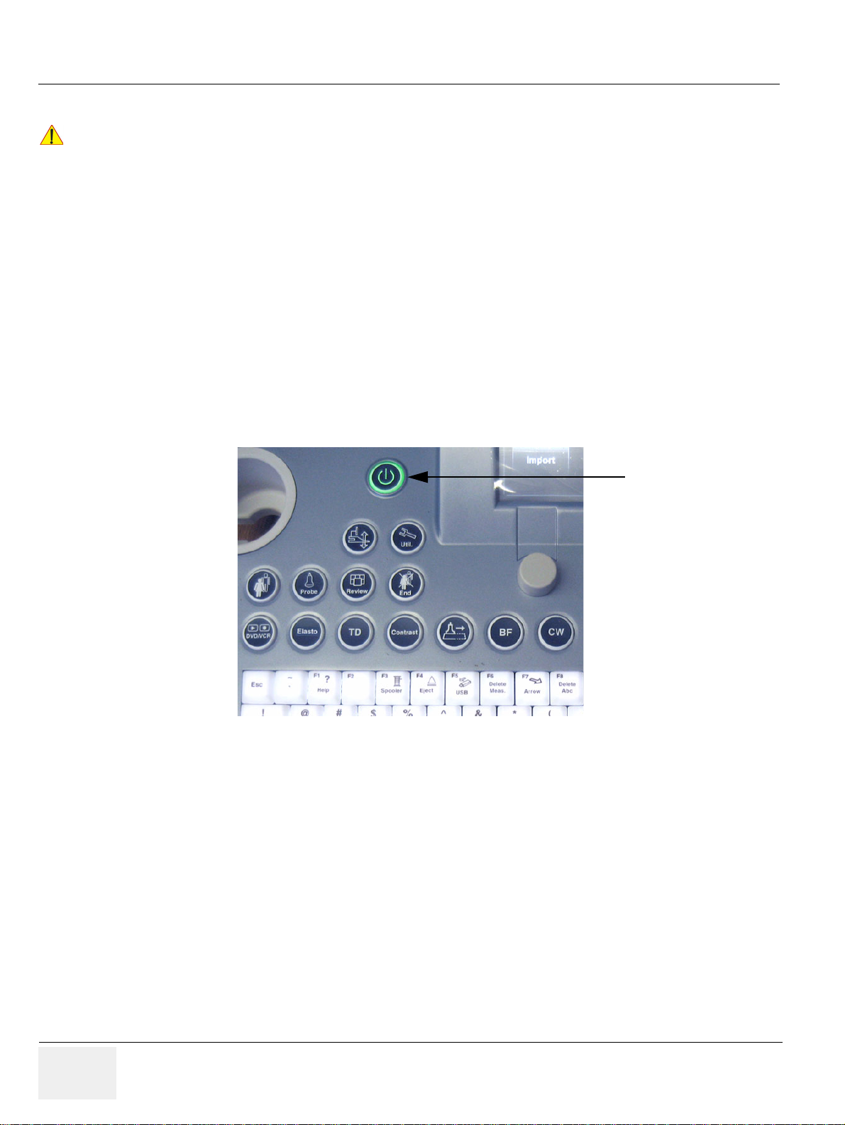
GE HEALTHCARERAFT VOLUSON E8 / VOLUSON E6
NOTICE
ON/OFF Standby
button
D
IRECTION KTD102576, REVISION 7 DRAFT (AUGUST 23, 2012) SERVICE MANUAL
3-6-2-2 Back End Processor Boot Up
When AC power is applied to the scanner, the ON/OFF Standby button on the control panel illuminates
!! NOTICE:
amber, indicating that the System (including the Back-end Processor) is in Standby mode.
5.) Hold down the ON/OFF Standby
button (see: Figure 3-26) on the control panel for ~3 seconds.
NOTE: The mains outlet of the system for peripheral auxiliary equipment are commonly switched with the
ON/OFF Standby button. The power switch of any attached printer(s) needs to be in ON position before
starting the system. However, be aware some auxiliary equipment may switch itself to standby mode
(e.g., Color video printer) and must therefore be switched on separately.
When the ON/OFF Stan dby button on the control panel is pressed, the System (including the Back-end
Processor) starts and the operating system is loaded which then leads the application software to
activate the scanner.
The system automatically performs an initialization sequence which includes the following:
- Loading the operating system.
- Running a quick diagnostic check of the system.
- Detecting connected probes
Figure 3-26 ON/OFF Standby button on Control Panel
As soon as the software has been loaded, the system enters 2D-Mode with the probe and application
that were used before the system was shut down.
NOTE: Total time used for start-up is about 2 minutes.
6.) Adjust Height and position of control console.
Refer to Section 6-5 "Control Console Positioning" on page 6-7.
3-32 Section 3-6 - Completing the Set Up
Page 99
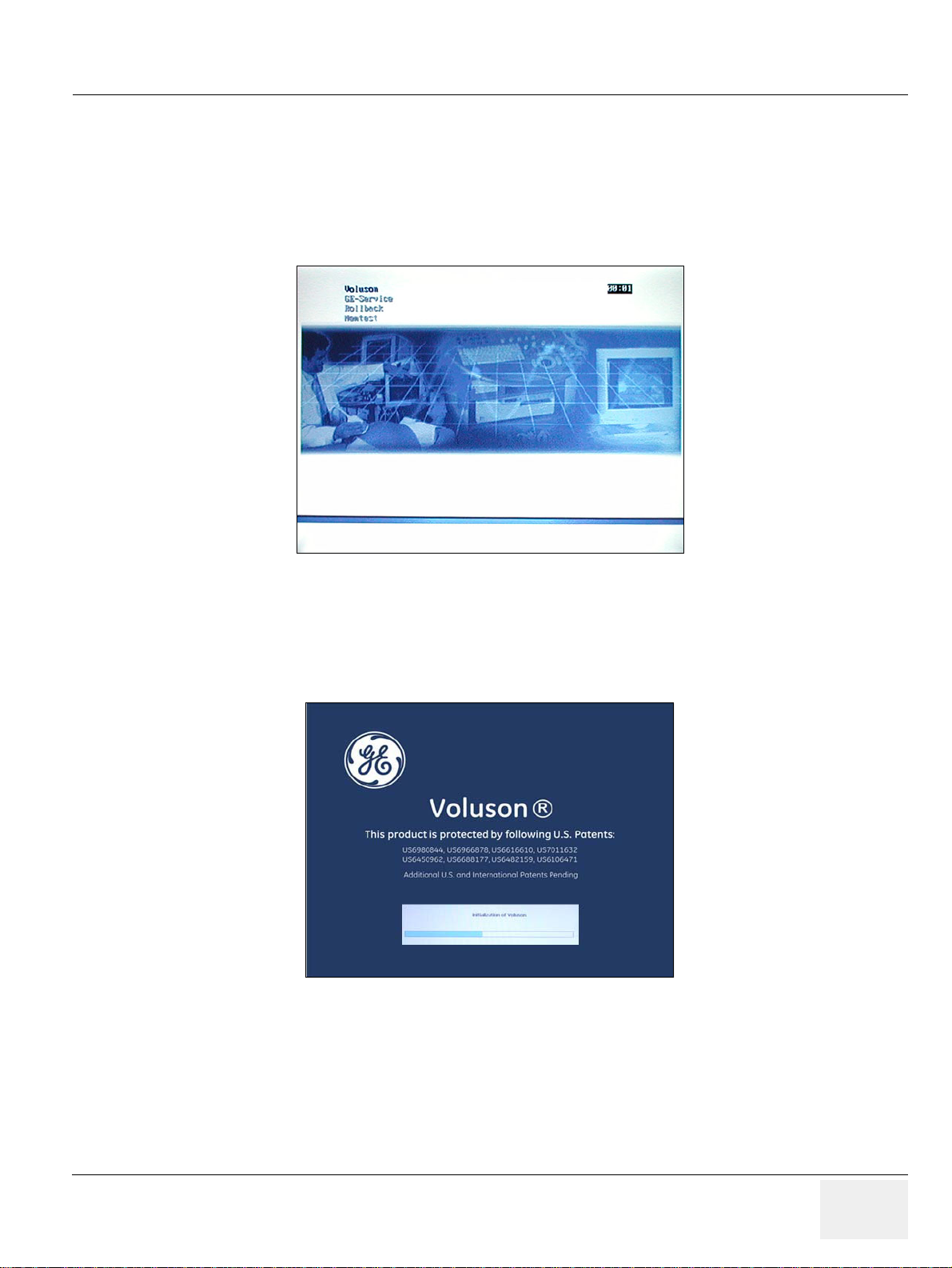
GE HEALTHCAREDRAFT VOLUSON E8 / VOLUSON E6
D
IRECTION KTD102576, REVISION 7 DRAFT (AUGUST 23, 2012) SERVICE MANUAL
3-6-2-3 During a normal boot, you may observe
A.) Power is distributed to Peripherals, Control panel, Monitor, Front-End and
Back-End Processor.
B.) The Back-End Processor and rest of the scanner starts with the sequence listed in following steps:
1.) First of all, the BIOS version is shown on the monitor.
2.) Afterwards the “Boot Screen” is displayed. (Voluson is highlighted, Figure 3-27 below).
Figure 3-27 Boot screen (e.g., BT12)
3.) Back-End Processor is turned ON and starts to load the software.
4.) The Start Screen (Voluson) is displayed on the monitor.
5.) Start-up progress bars indicating software loading procedures, are displayed on the monitor,
as shown in Figure 3-28 below.
Figure 3-28 GE Healthcare wallpaper with progress bar
6.) The software initiates and sets up the Front-End electronics and the rest of the scanner
(incl. the clicking sound of the relays on the RTF board).
7.) The Keyboard backlight is lit.
8.) As soon as the software has been loaded, the 2D screen is displayed on the monitor.
Chapter 3 - Setup Instructions 3-33
Page 100
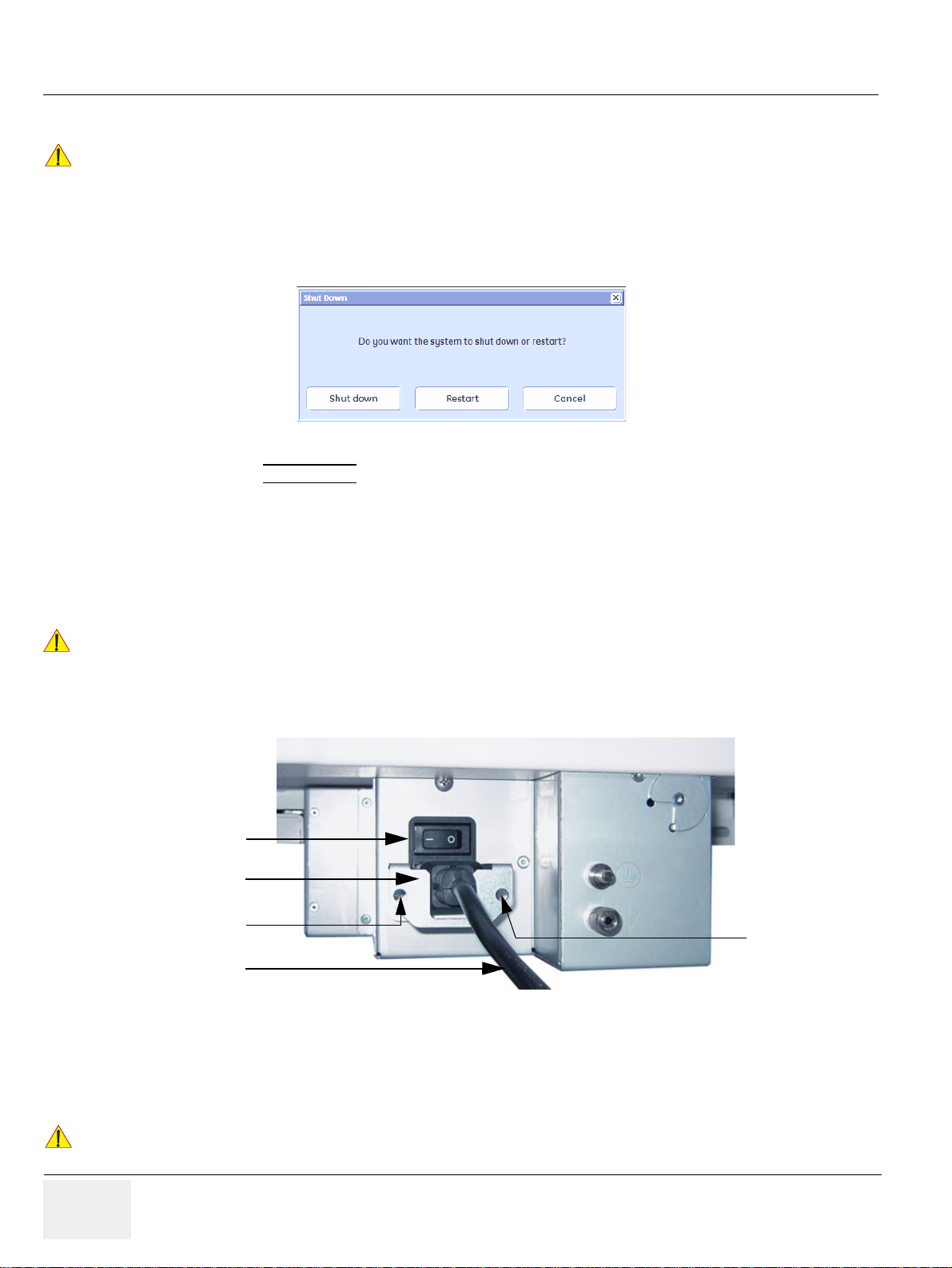
GE HEALTHCARERAFT VOLUSON E8 / VOLUSON E6
NOTICE
WARNINGWARNING
CAUTION
Circuit Breaker
Main Power Cable
pull-out protection
1 screw
1 screw
D
IRECTION KTD102576, REVISION 7 DRAFT (AUGUST 23, 2012) SERVICE MANUAL
3-6-3 Power Off / Shutdown
After turning off a system, wait at least 10 seconds before turning it on again.
!! NOTICE:
3-6-3-1 Scanner Shutdown
The system may not be able to boot if power is recycled too quickly.
1.) If not already in read mode, freeze the image.
2.) Press the ON/OFF Standby button (Figure 3-26) on the control panel. Follo wing dialog appears.
Figure 3-29 Shutdown, Restart or Cancel
3.) Select the SHUTDOWN
button. The system performs an automatic full shutdown sequence.
NOTE: Full shut down is also performed when pressing the ON/OFF Standby button on the control panel twice.
4.) Switch OFF the Circuit Breaker at the rear of the system.
NOTE: The mains outlet of the system for peripheral auxiliary equipment are commonly switched with the
ON/OFF Standby button. So the auxiliary equipment need not to be switched ON/OFF separately.
Disconnection of the Main Power Cable is necessary!
!! WARNING:
For Example: When repairing the system.
5.) After complete power down, unscrew the 2 screws and remove the pull-out protection to disco nnect
the main power cable from the system or unplug it from the AC wall outlet socket.
Figure 3-30 Circuit Breaker, pull-out protection and main power cable at rear of system
6.) Press on the brakes to block the front caster wheels.
7.) Disconnect probes. (Turn the probe locking handle counterclockwise and then pull the connector
straight out of the probe port.)
DO NOT disconnect a probe while running (Live Scan “Write” mode)!
!! CAUTION:
3-34 Section 3-6 - Completing the Set Up
A software error may occur. In this case switch the system OFF (perform a reset).
 Loading...