

Page 1

PRELIMINARY
11.SEP.2015
FN091065_BSP-BT12-VS5N-
GE
Vivid™ S5 N and Vivid™ S6 N
Service Manual
Vivid S5 N and Vivid S6 N software v12.x
BASIC SERVICE DOCUMENTATION.
COPYRIGHT GENERAL ELECTRIC COMPANY.
© 2013 and 2015 General Electric Company.
All Rights Reserved.
Part Number: FN091065
Revision: 2
Page 2

Page 3
PRELIMINARY
GE
P
ART NUMBER FN091065, REVISION 2 VS5 N AND VS6 N SERVICE MANUAL
Important Precautions
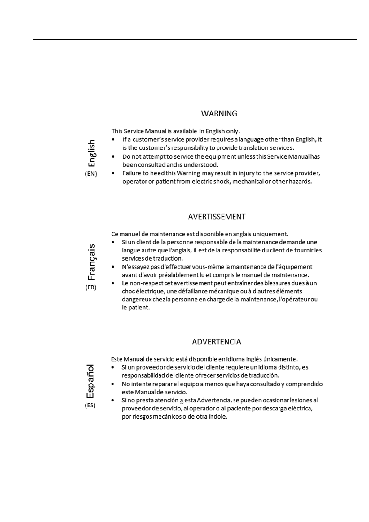
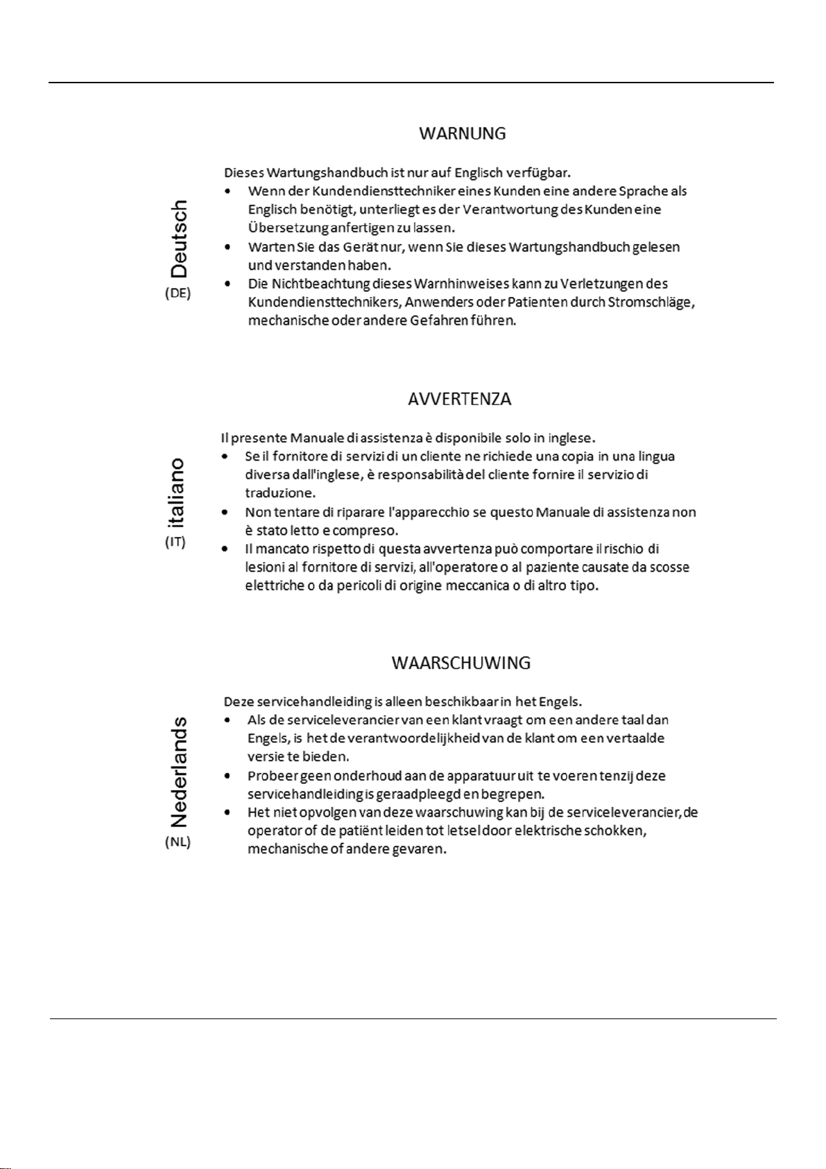
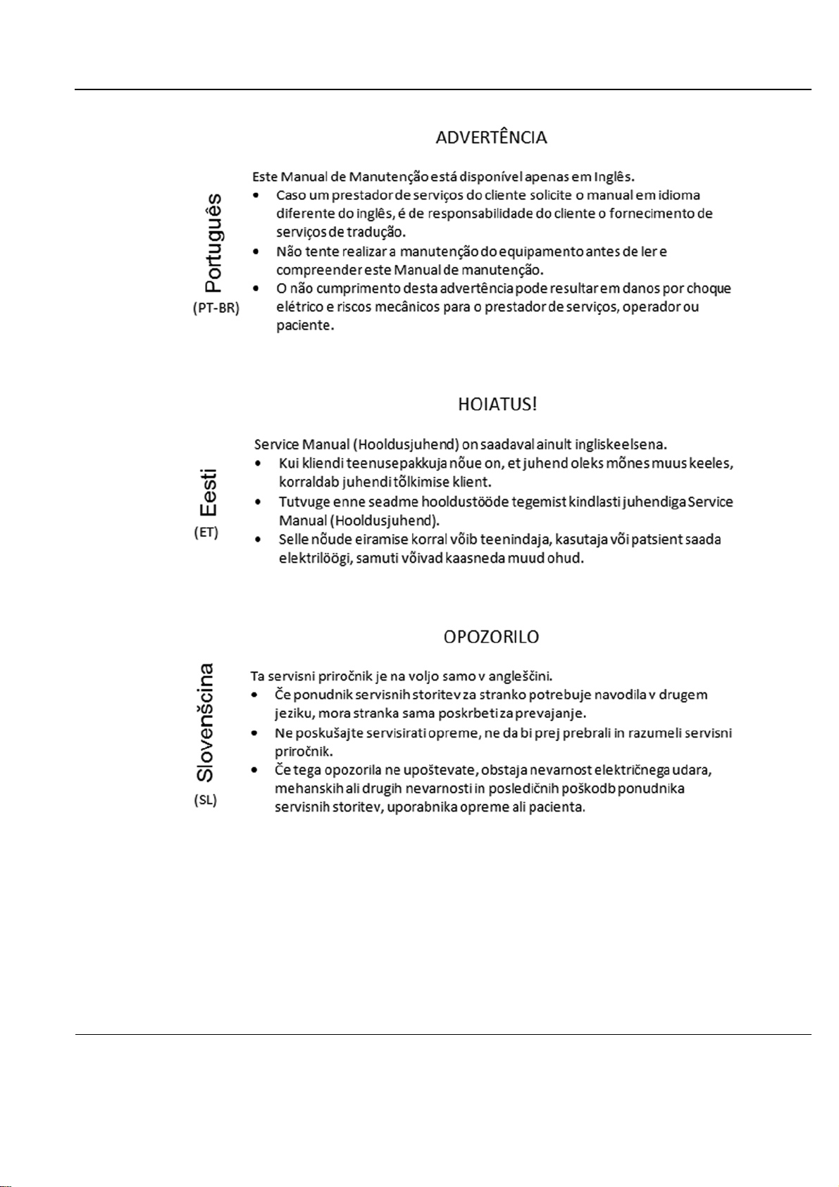
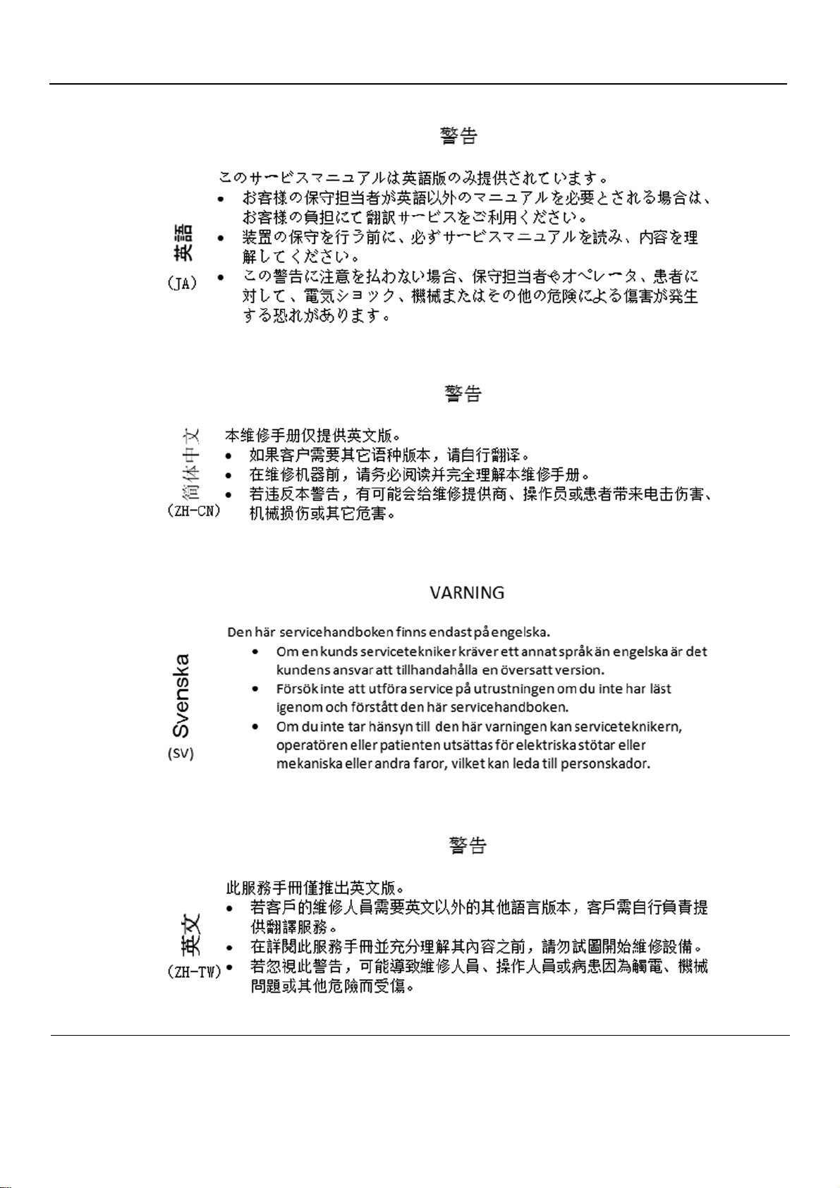
TRANSLATION POLICY
- i
Page 4
PRELIMINARY
GE
P
ART NUMBER FN091065, REVISION 2 VS5 N AND VS6 N SERVICE MANUAL
ii -
Page 5
PRELIMINARY
GE
P
ART NUMBER FN091065, REVISION 2 VS5 N AND VS6 N SERVICE MANUAL
- iii
Page 6
PRELIMINARY
GE
P
ART NUMBER FN091065, REVISION 2 VS5 N AND VS6 N SERVICE MANUAL
iv -
Page 7
PRELIMINARY
GE
P
ART NUMBER FN091065, REVISION 2 VS5 N AND VS6 N SERVICE MANUAL
- v
Page 8
PRELIMINARY
GE
P
ART NUMBER FN091065, REVISION 2 VS5 N AND VS6 N SERVICE MANUAL
vi -
Page 9
PRELIMINARY
GE
P
ART NUMBER FN091065, REVISION 2 VS5 N AND VS6 N SERVICE MANUAL
- vii
Page 10
PRELIMINARY
GE
P
ART NUMBER FN091065, REVISION 2 VS5 N AND VS6 N SERVICE MANUAL
viii -
Page 11
PRELIMINARY
GE
P
ART NUMBER FN091065, REVISION 2 VS5 N AND VS6 N SERVICE MANUAL
- ix
Page 12
PRELIMINARY
GE
P
ART NUMBER FN091065, REVISION 2 VS5 N AND VS6 N SERVICE MANUAL
x -
Page 13
PRELIMINARY
GE
P
ART NUMBER FN091065, REVISION 2 VS5 N AND VS6 N SERVICE MANUAL
- xi
Page 14
PRELIMINARY
GE
P
ART NUMBER FN091065, REVISION 2 VS5 N AND VS6 N SERVICE MANUAL
xii -
Page 15

PRELIMINARY
DANGER
WARNINGWARNING
GE
P
ART NUMBER FN091065, REVISION 2 VS5 N AND VS6 N SERVICE MANUAL
DAMAGE IN TRANSPORTATION
All packages should be closely examined at time of delivery. If damage is apparent write “Damage In
Shipment” on ALL copies of the freight or express bill BEFORE delivery is accepted or “signed for” by
a GE representative or hospital receiving agent. Whether noted or concealed , damage MUST be
reported to the carrier immediately upon discovery, or in any event, within 14 days after receipt, and the
contents and containers held for inspection by the carrier. A transportation company will not pay a claim
for damage if an inspection is not requested within this 14 day period.
CERTIFIED ELECTRICAL CONTRACTOR STATEMENT - FOR USA ONLY
All electrical Installations that are preliminary to positioning of the equipment at the site prepared for the
equipment shall be performed by licensed electrical contractors. Othe r conn ections between pieces o f
electrical equipment, calibrations and testing sh all be per fo rme d by qu a lifie d GE pe rso nne l. In
performing all electrical work on these products, GE will use its own specially trained field engineers.
All of GE’s electrical work on these products will comply with the requirements of the applicable
electrical codes.
The purchaser of GE equipment shall only utilize qualified personnel (i.e., GE’s field engineers,
personnel of third-party service companies with equivalent training, or licensed e lectricians) to perform
electrical servicing on the equipment.
OMISSIONS & ERRORS
If there are any omissions, errors or suggestions for improving this documentation, please contact the
GE Global Documentation Group with specific information listing the system type, manual title, part
number, revision number, page number and suggestion details.
Mail the information to:
Service Documentation,
GE Vingmed Ultrasound AS
P.O.Box: 141
NO 3191 HORTEN
NORWAY
GE Healthcare employees should use TrackWise to report service documentation issues. These issues
will then be in the internal problem reporting tool and communicated to the writer.
SERVICE SAFETY CONSIDERATIONS
DANGEROUS VOLTAGES, CAPABLE OF CAUSING DEATH, ARE PRESENT IN
THIS EQUIPMENT. USE EXTREME CAUTION WHEN HANDLING, TESTING AND
ADJUSTING.
Use all Personal Protection Equipment (PPE) such as gloves, safety shoes, safety
glasses, and kneeling pad, to reduce the risk of injury.
For a complete review of all safety requirement s, se e Section 1-3 "Safety Considerations" on page 1- 7.
- xiii
Page 16

PRELIMINARY
GE
P
ART NUMBER FN091065, REVISION 2 VS5 N AND VS6 N SERVICE MANUAL
LEGAL NOTES
The contents of this publication may not be copied or duplicated in any form, in whole or in part, without
prior written permission of GE.
GE may revise this publication from time to time without written notice.
TRADEMARKS
All products and their name brands are trademarks of their respective holders.
COPYRIGHTS
© 2013 and 2015 by General Electric Company Inc. All Rights Reserved.
xiv -
Page 17

PRELIMINARY
GE
P
ART NUMBER FN091065, REVISION 2 VS5 N AND VS6 N SERVICE MANUAL
Revision History
Revision Date Reason for change
1 2013 APR 23 Initial release (per BT12).
2 2015 SEP 11 Updated content.
List of Effected Pages (LOEP)
Pages Revision Pages Revision Pages Revision
Title Page 2 4-1 to 4-48 2 10-1 to 10-32 2
Front Matter 2 5-1 to 5-56 2 Back Cover N/A
TOC 2 6-1 to 6-10 2
1-1 to 1-30 2 7-1 to 7-142 2
2-1 to 2-14 2 8-1 to 8-256 2
3-1 to 3-193 2 9-1 to 9-18 2
- xv
Page 18

PRELIMINARY
GE
P
ART NUMBER FN091065, REVISION 2 VS5 N AND VS6 N SERVICE MANUAL
This page was intentionally left blank.
xvi -
Page 19

PRELIMINARY
GE
P
ART NUMBER FN091065REVISION 2 VS5 N AND VS6 N SERVICE MANUAL
CHAPTER 1
Introduction
Overview. . . . . . . . . . . . . . . . . . . . . . . . . . . . . . . . . . . . . . . . . . . . . . . . . . . . . . . . . 1 - 1
Purpose of Chapter 1 . . . . . . . . . . . . . . . . . . . . . . . . . . . . . . . . . . . . . . . . . 1 - 1
Purpose of Service Manual . . . . . . . . . . . . . . . . . . . . . . . . . . . . . . . . . . . . . 1 - 2
Typical Users of the Service Manual (This Manual) . . . . . . . . . . . . . . . . . . 1 - 2
Vivid™ S5 N and Vivid™ S6 N Models Covered in this Manual . . . . . . . . . 1 - 3
Product Description . . . . . . . . . . . . . . . . . . . . . . . . . . . . . . . . . . . . . . . . . . 1 - 4
Purpose of Operator Manual(s) . . . . . . . . . . . . . . . . . . . . . . . . . . . . . . . . . 1 - 4
Important Conventions . . . . . . . . . . . . . . . . . . . . . . . . . . . . . . . . . . . . . . . . . . . . . . 1 - 5
Conventions Used in this Manual . . . . . . . . . . . . . . . . . . . . . . . . . . . . . . . . 1 - 5
Safety Considerations . . . . . . . . . . . . . . . . . . . . . . . . . . . . . . . . . . . . . . . . . . . . . . 1 - 7
Introduction . . . . . . . . . . . . . . . . . . . . . . . . . . . . . . . . . . . . . . . . . . . . . . . . . 1 - 7
Human Safety . . . . . . . . . . . . . . . . . . . . . . . . . . . . . . . . . . . . . . . . . . . . . . . 1 - 7
Mechanical Safety . . . . . . . . . . . . . . . . . . . . . . . . . . . . . . . . . . . . . . . . . . . 1 - 9
Electrical Safety . . . . . . . . . . . . . . . . . . . . . . . . . . . . . . . . . . . . . . . . . . . . . 1 - 11
Vivid S5 N / Vivid S6 N Battery Safety . . . . . . . . . . . . . . . . . . . . . . . . . . . . 1 - 14
Patient Data Safety . . . . . . . . . . . . . . . . . . . . . . . . . . . . . . . . . . . . . . . . . . . 1 - 15
Dangerous Procedure Warnings . . . . . . . . . . . . . . . . . . . . . . . . . . . . . . . . 1 - 16
Lockout/Tagout (LOTO) requirements . . . . . . . . . . . . . . . . . . . . . . . . . . . . . . . . . . 1 - 17
Product Labels and Icons. . . . . . . . . . . . . . . . . . . . . . . . . . . . . . . . . . . . . . . . . . . . 1 - 18
Product Labels (Label, General info) . . . . . . . . . . . . . . . . . . . . . . . . . . . . . 1 - 18
Label Descriptions and Locations . . . . . . . . . . . . . . . . . . . . . . . . . . . . . . . . 1 - 20
Vivid™ S5 N and Vivid™ S6 N External Labels . . . . . . . . . . . . . . . . . . . . . 1 - 23
Returning/Shipping Probes and Repair Parts. . . . . . . . . . . . . . . . . . . . . . . . . . . . . 1 - 24
EMC, EMI, and ESD. . . . . . . . . . . . . . . . . . . . . . . . . . . . . . . . . . . . . . . . . . . . . . . . 1 - 25
Electromagnetic Compatibility (EMC) . . . . . . . . . . . . . . . . . . . . . . . . . . . . . 1 - 25
CE Compliance . . . . . . . . . . . . . . . . . . . . . . . . . . . . . . . . . . . . . . . . . . . . . . 1 - 25
Electrostatic Discharge (ESD) Prevention . . . . . . . . . . . . . . . . . . . . . . . . . 1 - 25
General Caution . . . . . . . . . . . . . . . . . . . . . . . . . . . . . . . . . . . . . . . . . . . . . 1 - 25
Customer Assistance . . . . . . . . . . . . . . . . . . . . . . . . . . . . . . . . . . . . . . . . . . . . . . . 1 - 27
Contact Information . . . . . . . . . . . . . . . . . . . . . . . . . . . . . . . . . . . . . . . . . . 1 - 27
System manufacturer . . . . . . . . . . . . . . . . . . . . . . . . . . . . . . . . . . . . . . . . . 1 - 29
- xvii
Page 20

PRELIMINARY
GE
P
ART NUMBER FN091065REVISION 2 VS5 N AND VS6 N SERVICE MANUAL
CHAPTER 2
Site Preparations
Overview . . . . . . . . . . . . . . . . . . . . . . . . . . . . . . . . . . . . . . . . . . . . . . . . . . . . . . . . . 2 - 1
Purpose of Chapter 2 . . . . . . . . . . . . . . . . . . . . . . . . . . . . . . . . . . . . . . . . . . 2 - 1
Console Requirements . . . . . . . . . . . . . . . . . . . . . . . . . . . . . . . . . . . . . . . . . . . . . . 2 - 2
Unit Environmental Requirements . . . . . . . . . . . . . . . . . . . . . . . . . . . . . . . . 2 - 2
Cooling Requirements . . . . . . . . . . . . . . . . . . . . . . . . . . . . . . . . . . . . . . . . . 2 - 2
Lighting Requirements . . . . . . . . . . . . . . . . . . . . . . . . . . . . . . . . . . . . . . . . . 2 - 2
Time and Manpower Requirements . . . . . . . . . . . . . . . . . . . . . . . . . . . . . . . 2 - 3
Electrical Requirements . . . . . . . . . . . . . . . . . . . . . . . . . . . . . . . . . . . . . . . . 2 - 4
EMI Limitations . . . . . . . . . . . . . . . . . . . . . . . . . . . . . . . . . . . . . . . . . . . . . . . 2 - 5
Probe Environmental Requirements . . . . . . . . . . . . . . . . . . . . . . . . . . . . . . 2 - 6
Facility Needs . . . . . . . . . . . . . . . . . . . . . . . . . . . . . . . . . . . . . . . . . . . . . . . . . . . . . 2 - 7
Purchaser Responsibilities . . . . . . . . . . . . . . . . . . . . . . . . . . . . . . . . . . . . . . 2 - 7
Mandatory Site Requirements . . . . . . . . . . . . . . . . . . . . . . . . . . . . . . . . . . . 2 - 8
Site Recommendations . . . . . . . . . . . . . . . . . . . . . . . . . . . . . . . . . . . . . . . . 2 - 8
Networking Pre-Installation Requirements . . . . . . . . . . . . . . . . . . . . . . . . . . 2 - 10
Connectivity Installation Worksheet. . . . . . . . . . . . . . . . . . . . . . . . . . . . . . . . . . . . . 2 - 11
xviii -
Page 21

PRELIMINARY
GE
P
ART NUMBER FN091065REVISION 2 VS5 N AND VS6 N SERVICE MANUAL
CHAPTER 3
System Setup
Overview. . . . . . . . . . . . . . . . . . . . . . . . . . . . . . . . . . . . . . . . . . . . . . . . . . . . . . . . . 3 - 1
Purpose of Chapter 3 . . . . . . . . . . . . . . . . . . . . . . . . . . . . . . . . . . . . . . . . . 3 - 1
Installation Reminders . . . . . . . . . . . . . . . . . . . . . . . . . . . . . . . . . . . . . . . . . . . . . . 3 - 2
Average Installation Time . . . . . . . . . . . . . . . . . . . . . . . . . . . . . . . . . . . . . . 3 - 2
Installation Warnings . . . . . . . . . . . . . . . . . . . . . . . . . . . . . . . . . . . . . . . . . 3 - 2
Safety Reminders . . . . . . . . . . . . . . . . . . . . . . . . . . . . . . . . . . . . . . . . . . . . 3 - 3
Receiving and Unpacking the Equipment. . . . . . . . . . . . . . . . . . . . . . . . . . . . . . . . 3 - 4
Unpacking the Cardboard Shipping Carton . . . . . . . . . . . . . . . . . . . . . . . . 3 - 8
Verifying the Shipping Carton Contents . . . . . . . . . . . . . . . . . . . . . . . . . . . 3 - 13
Physical Inspection . . . . . . . . . . . . . . . . . . . . . . . . . . . . . . . . . . . . . . . . . . . 3 - 13
EMI Protection . . . . . . . . . . . . . . . . . . . . . . . . . . . . . . . . . . . . . . . . . . . . . . 3 - 13
Preparing for Installation. . . . . . . . . . . . . . . . . . . . . . . . . . . . . . . . . . . . . . . . . . . . . 3 - 14
Confirming Customer Order . . . . . . . . . . . . . . . . . . . . . . . . . . . . . . . . . . . . 3 - 14
Language Change . . . . . . . . . . . . . . . . . . . . . . . . . . . . . . . . . . . . . . . . . . . 3 - 14
Component Inspection . . . . . . . . . . . . . . . . . . . . . . . . . . . . . . . . . . . . . . . . 3 - 18
System Voltage Confirmation . . . . . . . . . . . . . . . . . . . . . . . . . . . . . . . . . . . 3 - 24
Ensuring Protection from EMI . . . . . . . . . . . . . . . . . . . . . . . . . . . . . . . . . . . 3 - 25
Completing the Hardware Installation. . . . . . . . . . . . . . . . . . . . . . . . . . . . . . . . . . . 3 - 26
Connecting Printers . . . . . . . . . . . . . . . . . . . . . . . . . . . . . . . . . . . . . . . . . . 3 - 27
Connecting Peripherals . . . . . . . . . . . . . . . . . . . . . . . . . . . . . . . . . . . . . . . 3 - 66
Connecting Probes . . . . . . . . . . . . . . . . . . . . . . . . . . . . . . . . . . . . . . . . . . . 3 - 71
Connecting the ECG . . . . . . . . . . . . . . . . . . . . . . . . . . . . . . . . . . . . . . . . . . 3 - 73
Connecting the Unit to a Power Source . . . . . . . . . . . . . . . . . . . . . . . . . . . 3 - 75
Switching the System ON/OFF . . . . . . . . . . . . . . . . . . . . . . . . . . . . . . . . . . 3 - 79
Configuration . . . . . . . . . . . . . . . . . . . . . . . . . . . . . . . . . . . . . . . . . . . . . . . . . . . . . 3 - 80
Vivid S5 N and Vivid S6 N Configuration . . . . . . . . . . . . . . . . . . . . . . . . . . 3 - 80
Service Screen Set-up . . . . . . . . . . . . . . . . . . . . . . . . . . . . . . . . . . . . . . . . 3 - 85
Configuring Peripherals . . . . . . . . . . . . . . . . . . . . . . . . . . . . . . . . . . . . . . . 3 - 92
Software Options Configuration . . . . . . . . . . . . . . . . . . . . . . . . . . . . . . . . . 3 - 95
Connectivity Setup . . . . . . . . . . . . . . . . . . . . . . . . . . . . . . . . . . . . . . . . . . . . . . . . . 3 - 96
Connectivity Introduction . . . . . . . . . . . . . . . . . . . . . . . . . . . . . . . . . . . . . . 3 - 96
Physical Connection . . . . . . . . . . . . . . . . . . . . . . . . . . . . . . . . . . . . . . . . . . 3 - 103
Connectivity Configuration . . . . . . . . . . . . . . . . . . . . . . . . . . . . . . . . . . . . . 3 - 109
Set Up Connection to a DICOM Server in a Network . . . . . . . . . . . . . . . . . 3 - 120
- xix
Page 22

PRELIMINARY
GE
P
ART NUMBER FN091065REVISION 2 VS5 N AND VS6 N SERVICE MANUAL
Setup Connection to HL7 Server in a Network . . . . . . . . . . . . . . . . . . . . . . 3 - 125
Query/Retrieve (Q/R) Setup . . . . . . . . . . . . . . . . . . . . . . . . . . . . . . . . . . . . . 3 - 129
MPEGVue Export Configuration . . . . . . . . . . . . . . . . . . . . . . . . . . . . . . . . . 3 - 136
eVue Dataflow Configuration . . . . . . . . . . . . . . . . . . . . . . . . . . . . . . . . . . . . 3 - 141
Using MPEGVue/eVue on a Remote PC . . . . . . . . . . . . . . . . . . . . . . . . . . . 3 - 145
Storing and Transporting the Unit . . . . . . . . . . . . . . . . . . . . . . . . . . . . . . . . . . . . . . 3 - 186
Safety Precautions for Moving the Vivid S5 N or Vivid S6 N Unit . . . . . . . . 3 - 186
Cardboard Shipping Carton and Packaging Materials . . . . . . . . . . . . . . . . . 3 - 191
Completing the Installation Paperwork . . . . . . . . . . . . . . . . . . . . . . . . . . . . . . . . . . 3 - 192
Installation Acceptance Test Criteria . . . . . . . . . . . . . . . . . . . . . . . . . . . . . . 3 - 192
System Installation Details . . . . . . . . . . . . . . . . . . . . . . . . . . . . . . . . . . . . . . 3 - 192
Product Locator Installation . . . . . . . . . . . . . . . . . . . . . . . . . . . . . . . . . . . . . 3 - 192
User Manual(s) . . . . . . . . . . . . . . . . . . . . . . . . . . . . . . . . . . . . . . . . . . . . . . . 3 - 193
xx -
Page 23

PRELIMINARY
GE
P
ART NUMBER FN091065REVISION 2 VS5 N AND VS6 N SERVICE MANUAL
CHAPTER 4
Functional Checks
Overview. . . . . . . . . . . . . . . . . . . . . . . . . . . . . . . . . . . . . . . . . . . . . . . . . . . . . . . . . 4 - 1
Purpose of Chapter 4 . . . . . . . . . . . . . . . . . . . . . . . . . . . . . . . . . . . . . . . . . 4 - 1
Specific Equipment Required . . . . . . . . . . . . . . . . . . . . . . . . . . . . . . . . . . . 4 - 1
General Procedures . . . . . . . . . . . . . . . . . . . . . . . . . . . . . . . . . . . . . . . . . . . . . . . . 4 - 2
Overview . . . . . . . . . . . . . . . . . . . . . . . . . . . . . . . . . . . . . . . . . . . . . . . . . . . 4 - 2
Power ON/Boot-up . . . . . . . . . . . . . . . . . . . . . . . . . . . . . . . . . . . . . . . . . . . 4 - 2
Power Shut Down . . . . . . . . . . . . . . . . . . . . . . . . . . . . . . . . . . . . . . . . . . . . 4 - 7
Log On to the System as ADM . . . . . . . . . . . . . . . . . . . . . . . . . . . . . . . . . . 4 - 10
Using Removable Media . . . . . . . . . . . . . . . . . . . . . . . . . . . . . . . . . . . . . . . 4 - 12
Labeling Removable Media . . . . . . . . . . . . . . . . . . . . . . . . . . . . . . . . . . . . 4 - 14
Formatting Removable Media . . . . . . . . . . . . . . . . . . . . . . . . . . . . . . . . . . . 4 - 14
DICOM Repair of Removable Media . . . . . . . . . . . . . . . . . . . . . . . . . . . . . 4 - 15
Archiving and Restoring System Configuration . . . . . . . . . . . . . . . . . . . . . 4 - 15
Functional Checks . . . . . . . . . . . . . . . . . . . . . . . . . . . . . . . . . . . . . . . . . . . . . . . . . 4 - 18
Basic Controls . . . . . . . . . . . . . . . . . . . . . . . . . . . . . . . . . . . . . . . . . . . . . . . 4 - 18
Peripherals . . . . . . . . . . . . . . . . . . . . . . . . . . . . . . . . . . . . . . . . . . . . . . . . . 4 - 33
Mechanical Functional Tests . . . . . . . . . . . . . . . . . . . . . . . . . . . . . . . . . . . 4 - 35
Back End Processor Tests . . . . . . . . . . . . . . . . . . . . . . . . . . . . . . . . . . . . . 4 - 37
Image Testing. . . . . . . . . . . . . . . . . . . . . . . . . . . . . . . . . . . . . . . . . . . . . . . . . . . . . 4 - 38
2D Mode (B Mode) Checks . . . . . . . . . . . . . . . . . . . . . . . . . . . . . . . . . . . . 4 - 38
M Mode Checks . . . . . . . . . . . . . . . . . . . . . . . . . . . . . . . . . . . . . . . . . . . . . 4 - 39
Color Mode Checks . . . . . . . . . . . . . . . . . . . . . . . . . . . . . . . . . . . . . . . . . . 4 - 40
PW/CW Doppler Mode Checks . . . . . . . . . . . . . . . . . . . . . . . . . . . . . . . . . 4 - 42
Tissue Velocity Imaging (TVI) Checks . . . . . . . . . . . . . . . . . . . . . . . . . . . . 4 - 43
Probe/Connectors Check . . . . . . . . . . . . . . . . . . . . . . . . . . . . . . . . . . . . . . 4 - 44
System Turnover Checklist. . . . . . . . . . . . . . . . . . . . . . . . . . . . . . . . . . . . . . . . . . . 4 - 45
Software Configuration Checks . . . . . . . . . . . . . . . . . . . . . . . . . . . . . . . . . 4 - 45
Site Log . . . . . . . . . . . . . . . . . . . . . . . . . . . . . . . . . . . . . . . . . . . . . . . . . . . . . . . . . 4 - 46
- xxi
Page 24

PRELIMINARY
GE
P
ART NUMBER FN091065REVISION 2 VS5 N AND VS6 N SERVICE MANUAL
CHAPTER 5
Components and Function (Theory)
Overview . . . . . . . . . . . . . . . . . . . . . . . . . . . . . . . . . . . . . . . . . . . . . . . . . . . . . . . . . 5 - 1
Purpose of Chapter 5 . . . . . . . . . . . . . . . . . . . . . . . . . . . . . . . . . . . . . . . . . . 5 - 1
General Information. . . . . . . . . . . . . . . . . . . . . . . . . . . . . . . . . . . . . . . . . . . . . . . . . 5 - 1
Introduction . . . . . . . . . . . . . . . . . . . . . . . . . . . . . . . . . . . . . . . . . . . . . . . . . 5 - 2
Signal Flow . . . . . . . . . . . . . . . . . . . . . . . . . . . . . . . . . . . . . . . . . . . . . . . . . . 5 - 3
Vivid™ S5 N and Vivid™ S6 N Systems - Block Diagram . . . . . . . . . . . . . . 5 - 4
Front End Unit . . . . . . . . . . . . . . . . . . . . . . . . . . . . . . . . . . . . . . . . . . . . . . . . . . . . . 5 - 5
General Information . . . . . . . . . . . . . . . . . . . . . . . . . . . . . . . . . . . . . . . . . . . 5 - 5
Front End Unit - Location in the System . . . . . . . . . . . . . . . . . . . . . . . . . . . 5 - 8
RFI_AM Board . . . . . . . . . . . . . . . . . . . . . . . . . . . . . . . . . . . . . . . . . . . . . . . 5 - 10
TR32 Boards (Transmitter/Receiver) . . . . . . . . . . . . . . . . . . . . . . . . . . . . . . 5 - 14
Probe Select Board (PSB) . . . . . . . . . . . . . . . . . . . . . . . . . . . . . . . . . . . . . . 5 - 17
Probe Interface Board (PIB) . . . . . . . . . . . . . . . . . . . . . . . . . . . . . . . . . . . . . 5 - 19
Back End Processor . . . . . . . . . . . . . . . . . . . . . . . . . . . . . . . . . . . . . . . . . . . . . . . . 5 - 22
Introduction . . . . . . . . . . . . . . . . . . . . . . . . . . . . . . . . . . . . . . . . . . . . . . . . . 5 - 22
ETX SBC Central Processing Unit (CPU) . . . . . . . . . . . . . . . . . . . . . . . . . . 5 - 24
ETX Base Board . . . . . . . . . . . . . . . . . . . . . . . . . . . . . . . . . . . . . . . . . . . . . 5 - 25
Hard Disk . . . . . . . . . . . . . . . . . . . . . . . . . . . . . . . . . . . . . . . . . . . . . . . . . . . 5 - 26
Fan Control . . . . . . . . . . . . . . . . . . . . . . . . . . . . . . . . . . . . . . . . . . . . . . . . . 5 - 27
Temperature Control . . . . . . . . . . . . . . . . . . . . . . . . . . . . . . . . . . . . . . . . . . 5 - 27
RTC Battery . . . . . . . . . . . . . . . . . . . . . . . . . . . . . . . . . . . . . . . . . . . . . . . . . 5 - 27
Back End Processor - Location of Components . . . . . . . . . . . . . . . . . . . . . 5 - 28
Internal and External Input/Output (I/O). . . . . . . . . . . . . . . . . . . . . . . . . . . . . . . . . . 5 - 31
DIB - Interconnections . . . . . . . . . . . . . . . . . . . . . . . . . . . . . . . . . . . . . . . . . 5 - 34
Power Supply System . . . . . . . . . . . . . . . . . . . . . . . . . . . . . . . . . . . . . . . . . . . . . . . 5 - 38
Electrical Power . . . . . . . . . . . . . . . . . . . . . . . . . . . . . . . . . . . . . . . . . . . . . . 5 - 38
Introduction . . . . . . . . . . . . . . . . . . . . . . . . . . . . . . . . . . . . . . . . . . . . . . . . . 5 - 38
AC Distribution Panel . . . . . . . . . . . . . . . . . . . . . . . . . . . . . . . . . . . . . . . . . . 5 - 39
Power Supply Unit Components . . . . . . . . . . . . . . . . . . . . . . . . . . . . . . . . . 5 - 42
DC Source Selector . . . . . . . . . . . . . . . . . . . . . . . . . . . . . . . . . . . . . . . . . . . 5 - 42
Rechargeable Battery Pack Assy (GPA) . . . . . . . . . . . . . . . . . . . . . . . . . . . 5 - 43
Top Console with Monitor and Operator Panel . . . . . . . . . . . . . . . . . . . . . . . . . . . . 5 - 45
Keyboard and Operator Panel . . . . . . . . . . . . . . . . . . . . . . . . . . . . . . . . . . . 5 - 45
Keyboard and Operator Panel Components . . . . . . . . . . . . . . . . . . . . . . . . 5 - 46
xxii -
Page 25

PRELIMINARY
GE
P
ART NUMBER FN091065REVISION 2 VS5 N AND VS6 N SERVICE MANUAL
ECG Module. . . . . . . . . . . . . . . . . . . . . . . . . . . . . . . . . . . . . . . . . . . . . . . . . . . . . . 5 - 50
Overview . . . . . . . . . . . . . . . . . . . . . . . . . . . . . . . . . . . . . . . . . . . . . . . . . . . 5 - 50
ECG Patient I/O Module Specifications . . . . . . . . . . . . . . . . . . . . . . . . . . . 5 - 51
Isolation . . . . . . . . . . . . . . . . . . . . . . . . . . . . . . . . . . . . . . . . . . . . . . . . . . . 5 - 51
Peripherals . . . . . . . . . . . . . . . . . . . . . . . . . . . . . . . . . . . . . . . . . . . . . . . . . . . . . . . 5 - 52
Introduction . . . . . . . . . . . . . . . . . . . . . . . . . . . . . . . . . . . . . . . . . . . . . . . . . 5 - 52
Cooling System . . . . . . . . . . . . . . . . . . . . . . . . . . . . . . . . . . . . . . . . . . . . . . . . . . . 5 - 54
General Information . . . . . . . . . . . . . . . . . . . . . . . . . . . . . . . . . . . . . . . . . . 5 - 54
Common Service Platform . . . . . . . . . . . . . . . . . . . . . . . . . . . . . . . . . . . . . . . . . . . 5 - 55
Introduction . . . . . . . . . . . . . . . . . . . . . . . . . . . . . . . . . . . . . . . . . . . . . . . . . 5 - 55
Global Service User Interface (GSUI) . . . . . . . . . . . . . . . . . . . . . . . . . . . . . 5 - 55
- xxiii
Page 26

PRELIMINARY
GE
P
ART NUMBER FN091065REVISION 2 VS5 N AND VS6 N SERVICE MANUAL
CHAPTER 6
Service Adjustments
Overview . . . . . . . . . . . . . . . . . . . . . . . . . . . . . . . . . . . . . . . . . . . . . . . . . . . . . . . . . 6 - 1
Purpose of Chapter 6 . . . . . . . . . . . . . . . . . . . . . . . . . . . . . . . . . . . . . . . . . . 6 - 1
LCD Display Adjustments and Calibration . . . . . . . . . . . . . . . . . . . . . . . . . . 6 - 1
Keyboard Adjustments . . . . . . . . . . . . . . . . . . . . . . . . . . . . . . . . . . . . . . . . . 6 - 9
Trackball Speed Setting . . . . . . . . . . . . . . . . . . . . . . . . . . . . . . . . . . . . . . . . 6 - 9
Beamformer Calibration . . . . . . . . . . . . . . . . . . . . . . . . . . . . . . . . . . . . . . . . 6 - 9
xxiv -
Page 27

PRELIMINARY
GE
P
ART NUMBER FN091065REVISION 2 VS5 N AND VS6 N SERVICE MANUAL
CHAPTER 7
Diagnostics/Troubleshooting
Overview. . . . . . . . . . . . . . . . . . . . . . . . . . . . . . . . . . . . . . . . . . . . . . . . . . . . . . . . . 7 - 1
Purpose of Chapter . . . . . . . . . . . . . . . . . . . . . . . . . . . . . . . . . . . . . . . . . . . 7 - 1
Diagnostics. . . . . . . . . . . . . . . . . . . . . . . . . . . . . . . . . . . . . . . . . . . . . . . . . . . . . . . 7 - 2
Diagnostic Tools . . . . . . . . . . . . . . . . . . . . . . . . . . . . . . . . . . . . . . . . . . . . . 7 - 2
Diagnostic Procedure Summary . . . . . . . . . . . . . . . . . . . . . . . . . . . . . . . . . 7 - 2
Accessing the Diagnostic Test Window . . . . . . . . . . . . . . . . . . . . . . . . . . . 7 - 3
Diagnostic Test Window Menu Options . . . . . . . . . . . . . . . . . . . . . . . . . . . 7 - 11
Performing Full System Diagnostics. . . . . . . . . . . . . . . . . . . . . . . . . . . . . . . . . . . . 7 - 21
Accessing the Full System Diagnostic Options . . . . . . . . . . . . . . . . . . . . . 7 - 22
Performing Front End (FE) Diagnostics . . . . . . . . . . . . . . . . . . . . . . . . . . . . . . . . . 7 - 26
Accessing the Front End Diagnostic Options . . . . . . . . . . . . . . . . . . . . . . . 7 - 27
Calibration Tests . . . . . . . . . . . . . . . . . . . . . . . . . . . . . . . . . . . . . . . . . . . . . 7 - 27
Radio Frequency Interface (RFI) Diagnostic Tests . . . . . . . . . . . . . . . . . . . 7 - 33
TR 32 Diagnostic Tests . . . . . . . . . . . . . . . . . . . . . . . . . . . . . . . . . . . . . . . 7 - 47
Probe Interface Board Diagnostic Tests . . . . . . . . . . . . . . . . . . . . . . . . . . . 7 - 62
Probe Select Board Diagnostic Tests . . . . . . . . . . . . . . . . . . . . . . . . . . . . . 7 - 63
Monitoring Tests. . . . . . . . . . . . . . . . . . . . . . . . . . . . . . . . . . . . . . . . . . . . . . . . . . . 7 - 90
Accessing the Monitoring Diagnostic Test Options . . . . . . . . . . . . . . . . . . 7 - 90
Performing Back End Diagnostics on the System . . . . . . . . . . . . . . . . . . . . . . . . . 7 - 113
Accessing the Back End Diagnostic Test Options . . . . . . . . . . . . . . . . . . . 7 - 113
Automatic Error Log . . . . . . . . . . . . . . . . . . . . . . . . . . . . . . . . . . . . . . . . . . . . . . . . 7 - 132
Adding Bookmarks . . . . . . . . . . . . . . . . . . . . . . . . . . . . . . . . . . . . . . . . . . . 7 - 132
Extracting Logs . . . . . . . . . . . . . . . . . . . . . . . . . . . . . . . . . . . . . . . . . . . . . . 7 - 132
- xxv
Page 28

PRELIMINARY
GE
P
ART NUMBER FN091065REVISION 2 VS5 N AND VS6 N SERVICE MANUAL
CHAPTER 8
Replacement Procedures
Overview . . . . . . . . . . . . . . . . . . . . . . . . . . . . . . . . . . . . . . . . . . . . . . . . . . . . . . . . . 8 - 1
Purpose of Chapter 8 . . . . . . . . . . . . . . . . . . . . . . . . . . . . . . . . . . . . . . . . . . 8 - 1
Cover Replacement Procedures . . . . . . . . . . . . . . . . . . . . . . . . . . . . . . . . . . . . . . . 8 - 2
Overview of Covers . . . . . . . . . . . . . . . . . . . . . . . . . . . . . . . . . . . . . . . . . . . 8 - 2
Right Side Cover Replacement Procedure . . . . . . . . . . . . . . . . . . . . . . . . . 8 - 4
Left Side Cover Replacement Procedure . . . . . . . . . . . . . . . . . . . . . . . . . . . 8 - 6
Right Rear Cover Replacement Procedures . . . . . . . . . . . . . . . . . . . . . . . . 8 - 10
Left Rear Cover Replacement Procedures . . . . . . . . . . . . . . . . . . . . . . . . . 8 - 13
Front Cover Replacement Procedures . . . . . . . . . . . . . . . . . . . . . . . . . . . . . 8 - 17
Basket Replacement Procedure . . . . . . . . . . . . . . . . . . . . . . . . . . . . . . . . . 8 - 20
Rear Folder Box Replacement Procedure . . . . . . . . . . . . . . . . . . . . . . . . . . 8 - 21
Tray Replacement Procedure . . . . . . . . . . . . . . . . . . . . . . . . . . . . . . . . . . . 8 - 22
Bottom Rear Cover Replacement Procedures . . . . . . . . . . . . . . . . . . . . . . . 8 - 23
DVD Cover Replacement Procedure . . . . . . . . . . . . . . . . . . . . . . . . . . . . . . 8 - 24
Control Console Components Replacement Procedures . . . . . . . . . . . . . . . . . . . . 8 - 26
Monitor Replacement Procedure . . . . . . . . . . . . . . . . . . . . . . . . . . . . . . . . . 8 - 26
Monitor Arm Replacement Procedure . . . . . . . . . . . . . . . . . . . . . . . . . . . . . 8 - 30
Monitor Cover Replacement Procedure . . . . . . . . . . . . . . . . . . . . . . . . . . . . 8 - 37
Keyboard Assembly Replacement Procedure . . . . . . . . . . . . . . . . . . . . . . . 8 - 39
Keyboard Interface Assembly Replacement Procedure . . . . . . . . . . . . . . . 8 - 44
Probe Shelf Replacement Procedure . . . . . . . . . . . . . . . . . . . . . . . . . . . . . . 8 - 52
Swivel and Up-Down Handle Replacement Procedure . . . . . . . . . . . . . . . . 8 - 53
Rear Handle Replacement Procedure . . . . . . . . . . . . . . . . . . . . . . . . . . . . . 8 - 56
Keyboard Assembly Replacement Procedures . . . . . . . . . . . . . . . . . . . . . . . . . . . . 8 - 59
Keyboard Bottom Cover Replacement Procedure . . . . . . . . . . . . . . . . . . . . 8 - 59
Upper Arm Replacement Procedure . . . . . . . . . . . . . . . . . . . . . . . . . . . . . . 8 - 61
Joint Assembly Replacement Procedure . . . . . . . . . . . . . . . . . . . . . . . . . . . 8 - 65
Alphanumeric Keyboard Replacement Procedure . . . . . . . . . . . . . . . . . . . . 8 - 69
Mechanical Trackball and Housing Replacement Procedure . . . . . . . . . . . 8 - 71
TGC Board Replacement Procedure (New-type Operator Panel) . . . . . . . . 8 - 74
TGC Board Replacement Procedure (Old-type Operator Panel) . . . . . . . . . 8 - 77
Extended Keyboard Replacement Procedure (New-type Operator Panel) . 8 - 79
Extended Keyboard Replacement Procedure (Old-type Operator Panel) . . 8 - 82
LEDs and Soft Menu Board Replacement (New-type OP) . . . . . . . . . . . . . 8 - 86
LEDs and Soft Menu Board Replacement (Old-type OP) . . . . . . . . . . . . . . 8 - 88
Alphanumeric Keycap Replacement Procedure . . . . . . . . . . . . . . . . . . . . . 8 - 90
xxvi -
Page 29

PRELIMINARY
GE
P
ART NUMBER FN091065REVISION 2 VS5 N AND VS6 N SERVICE MANUAL
Rotary Knob Replacement Procedure . . . . . . . . . . . . . . . . . . . . . . . . . . . . 8 - 91
ATGC Keycap Replacement Procedure . . . . . . . . . . . . . . . . . . . . . . . . . . . 8 - 92
Speaker Replacement Procedure . . . . . . . . . . . . . . . . . . . . . . . . . . . . . . . . 8 - 93
Cable Replacement Procedures. . . . . . . . . . . . . . . . . . . . . . . . . . . . . . . . . . . . . . . 8 - 95
Keyboard and Monitor Cable Replacement Procedure . . . . . . . . . . . . . . . 8 - 95
Lower Section Components Replacement Procedures . . . . . . . . . . . . . . . . . . . . . 8 - 109
Opening and Removing the Cabinet Cage Assembly . . . . . . . . . . . . . . . . 8 - 109
Battery Replacement Procedure . . . . . . . . . . . . . . . . . . . . . . . . . . . . . . . . . 8 - 116
Battery Bracket Replacement Procedure . . . . . . . . . . . . . . . . . . . . . . . . . . 8 - 119
Hard Disk Replacement Procedure . . . . . . . . . . . . . . . . . . . . . . . . . . . . . . 8 - 122
BEP Replacement Procedure . . . . . . . . . . . . . . . . . . . . . . . . . . . . . . . . . . 8 - 134
ECG Module Assembly Replacement Procedure . . . . . . . . . . . . . . . . . . . . 8 - 140
DC-to-DC Power Supply Replacement Procedure . . . . . . . . . . . . . . . . . . . 8 - 145
PSB (Probe Select Board) Board Replacement Procedure . . . . . . . . . . . . 8 - 148
PIB (Probe Interface Board) Board Replacement Procedure . . . . . . . . . . . 8 - 153
TR32 and RFI Boards Replacement Procedure . . . . . . . . . . . . . . . . . . . . . 8 - 156
Fans and Fan Board Replacement Procedure . . . . . . . . . . . . . . . . . . . . . . 8 - 164
Peripherals AC Outlet Connectors Panel Replacement Procedure . . . . . . 8 - 167
Sub-woofer Assembly Replacement Procedure . . . . . . . . . . . . . . . . . . . . . 8 - 172
DIB (Distribution Interface Board) Replacement Procedure . . . . . . . . . . . . 8 - 174
AC Distribution Box (Type B) Replacement Procedure . . . . . . . . . . . . . . . 8 - 177
AC Distribution Box (Type A-to-Type B) Replacement Procedure . . . . . . . 8 - 180
AC Distribution Box (Type A) Replacement Procedure . . . . . . . . . . . . . . . 8 - 184
Mechanical Components Replacement Procedures . . . . . . . . . . . . . . . . . . . . . . . 8 - 189
Foot Rest Replacement Procedure . . . . . . . . . . . . . . . . . . . . . . . . . . . . . . 8 - 189
Brake and Swivel Locking Wheels Replacement Procedure . . . . . . . . . . . 8 - 191
Lower Arm Replacement Procedure . . . . . . . . . . . . . . . . . . . . . . . . . . . . . . 8 - 193
Gas Spring Replacement Procedure . . . . . . . . . . . . . . . . . . . . . . . . . . . . . 8 - 198
Probe Cable Holder Replacement Procedure . . . . . . . . . . . . . . . . . . . . . . 8 - 203
Software Loading . . . . . . . . . . . . . . . . . . . . . . . . . . . . . . . . . . . . . . . . . . . . . . . . . . 8 - 207
Software Upgrade Procedure Overview . . . . . . . . . . . . . . . . . . . . . . . . . . . 8 - 207
Preparation . . . . . . . . . . . . . . . . . . . . . . . . . . . . . . . . . . . . . . . . . . . . . . . . . 8 - 209
Software Upgrade/Installation/Reinstallation - BT10 to BT12 . . . . . . . . . . . 8 - 213
Vivid™ S5 N and Vivid™ S6 N Software Re-Installation Procedure . . . . . 8 - 222
Loading Latest Version User Manuals . . . . . . . . . . . . . . . . . . . . . . . . . . . . 8 - 226
Setting the BIOS . . . . . . . . . . . . . . . . . . . . . . . . . . . . . . . . . . . . . . . . . . . . . 8 - 228
Formatting and Partitioning the Hard Disk - Automatic Procedure . . . . . . . 8 - 230
Alphanumeric Keyboard Firmware Update . . . . . . . . . . . . . . . . . . . . . . . . . 8 - 232
Performing a Complete System Back-up . . . . . . . . . . . . . . . . . . . . . . . . . . 8 - 233
- xxvii
Page 30

PRELIMINARY
GE
P
ART NUMBER FN091065REVISION 2 VS5 N AND VS6 N SERVICE MANUAL
How to Restore User-defined Presets . . . . . . . . . . . . . . . . . . . . . . . . . . . . . 8 - 233
Peripherals - Replacement Procedures. . . . . . . . . . . . . . . . . . . . . . . . . . . . . . . . . . 8 - 234
Wireless USB Network Adaptor Replacement Procedure . . . . . . . . . . . . . . 8 - 234
DVD/CD-RW Drive Replacement Procedure . . . . . . . . . . . . . . . . . . . . . . . . 8 - 236
MOD Drive Replacement Procedure . . . . . . . . . . . . . . . . . . . . . . . . . . . . . . 8 - 240
External USB Hard Disk Replacement Procedure . . . . . . . . . . . . . . . . . . . . 8 - 242
Black and White Printer Replacement Procedure . . . . . . . . . . . . . . . . . . . . 8 - 247
Peripherals Console Replacement Procedure . . . . . . . . . . . . . . . . . . . . . . . 8 - 250
Digital Color Printer Replacement Procedure . . . . . . . . . . . . . . . . . . . . . . . 8 - 253
DeskJet Color Printer Replacement Procedure . . . . . . . . . . . . . . . . . . . . . . 8 - 255
xxviii -
Page 31

PRELIMINARY
GE
P
ART NUMBER FN091065REVISION 2 VS5 N AND VS6 N SERVICE MANUAL
CHAPTER 9
Renewal Parts
Overview. . . . . . . . . . . . . . . . . . . . . . . . . . . . . . . . . . . . . . . . . . . . . . . . . . . . . . . . . 9 - 1
Purpose of Chapter 9 . . . . . . . . . . . . . . . . . . . . . . . . . . . . . . . . . . . . . . . . . 9 - 1
List of Abbreviations. . . . . . . . . . . . . . . . . . . . . . . . . . . . . . . . . . . . . . . . . . . . . . . . 9 - 2
Covers . . . . . . . . . . . . . . . . . . . . . . . . . . . . . . . . . . . . . . . . . . . . . . . . . . . . . . . . . . 9 - 3
Mechanical Hardware Parts . . . . . . . . . . . . . . . . . . . . . . . . . . . . . . . . . . . . . . . . . . 9 - 5
Electro Mechanical Parts . . . . . . . . . . . . . . . . . . . . . . . . . . . . . . . . . . . . . . . . . . . . 9 - 7
Electronic Parts . . . . . . . . . . . . . . . . . . . . . . . . . . . . . . . . . . . . . . . . . . . . . . . . . . . 9 - 8
Cables . . . . . . . . . . . . . . . . . . . . . . . . . . . . . . . . . . . . . . . . . . . . . . . . . . . . . . . . . . 9 - 11
Software . . . . . . . . . . . . . . . . . . . . . . . . . . . . . . . . . . . . . . . . . . . . . . . . . . . . . . . . . 9 - 15
Probes . . . . . . . . . . . . . . . . . . . . . . . . . . . . . . . . . . . . . . . . . . . . . . . . . . . . . . . . . . 9 - 16
Peripherals . . . . . . . . . . . . . . . . . . . . . . . . . . . . . . . . . . . . . . . . . . . . . . . . . . . . . . . 9 - 18
- xxix
Page 32

PRELIMINARY
GE
P
ART NUMBER FN091065REVISION 2 VS5 N AND VS6 N SERVICE MANUAL
CHAPTER 10
Care and Maintenance
Overview . . . . . . . . . . . . . . . . . . . . . . . . . . . . . . . . . . . . . . . . . . . . . . . . . . . . . . . . . 10 - 1
Periodic Maintenance Inspections . . . . . . . . . . . . . . . . . . . . . . . . . . . . . . . . 10 - 1
Purpose of Chapter 10 . . . . . . . . . . . . . . . . . . . . . . . . . . . . . . . . . . . . . . . . . 10 - 1
Warnings . . . . . . . . . . . . . . . . . . . . . . . . . . . . . . . . . . . . . . . . . . . . . . . . . . . 10 - 2
Why Perform Maintenance Procedures?. . . . . . . . . . . . . . . . . . . . . . . . . . . . . . . . . 10 - 3
Keeping Records . . . . . . . . . . . . . . . . . . . . . . . . . . . . . . . . . . . . . . . . . . . . . 10 - 3
Quality Assurance . . . . . . . . . . . . . . . . . . . . . . . . . . . . . . . . . . . . . . . . . . . . 10 - 3
Maintenance Task Schedule . . . . . . . . . . . . . . . . . . . . . . . . . . . . . . . . . . . . . . . . . . 10 - 4
How Often Should Care & Maintenance Procedures be Performed? . . . . . 10 - 4
System Maintenance . . . . . . . . . . . . . . . . . . . . . . . . . . . . . . . . . . . . . . . . . . . . . . . . 10 - 6
Preliminary Checks . . . . . . . . . . . . . . . . . . . . . . . . . . . . . . . . . . . . . . . . . . . 10 - 6
Functional Checks . . . . . . . . . . . . . . . . . . . . . . . . . . . . . . . . . . . . . . . . . . . . 10 - 7
Input Power Checks . . . . . . . . . . . . . . . . . . . . . . . . . . . . . . . . . . . . . . . . . . . 10 - 8
Cleaning . . . . . . . . . . . . . . . . . . . . . . . . . . . . . . . . . . . . . . . . . . . . . . . . . . . . 10 - 9
Physical Inspection . . . . . . . . . . . . . . . . . . . . . . . . . . . . . . . . . . . . . . . . . . . 10 - 13
Optional Diagnostic Checks . . . . . . . . . . . . . . . . . . . . . . . . . . . . . . . . . . . . . 10 - 14
Probe Maintenance . . . . . . . . . . . . . . . . . . . . . . . . . . . . . . . . . . . . . . . . . . . . . . . . . 10 - 15
Probe Checks . . . . . . . . . . . . . . . . . . . . . . . . . . . . . . . . . . . . . . . . . . . . . . . . 10 - 15
Probe Handling . . . . . . . . . . . . . . . . . . . . . . . . . . . . . . . . . . . . . . . . . . . . . . 10 - 15
Basic Probe Care . . . . . . . . . . . . . . . . . . . . . . . . . . . . . . . . . . . . . . . . . . . . . 10 - 16
Probe Cleaning . . . . . . . . . . . . . . . . . . . . . . . . . . . . . . . . . . . . . . . . . . . . . . 10 - 16
Returning and Shipping of Defective Probes . . . . . . . . . . . . . . . . . . . . . . . . 10 - 19
Electrical Safety Tests . . . . . . . . . . . . . . . . . . . . . . . . . . . . . . . . . . . . . . . . . . . . . . . 10 - 20
Safety Test Overview . . . . . . . . . . . . . . . . . . . . . . . . . . . . . . . . . . . . . . . . . . 10 - 20
Current Leakage Limits . . . . . . . . . . . . . . . . . . . . . . . . . . . . . . . . . . . . . . . . 10 - 21
Outlet Test Wiring Arrangement - USA & Canada . . . . . . . . . . . . . . . . . . . . 10 - 22
Grounding Continuity . . . . . . . . . . . . . . . . . . . . . . . . . . . . . . . . . . . . . . . . . 10 - 23
Chassis Current Leakage Test . . . . . . . . . . . . . . . . . . . . . . . . . . . . . . . . . . . 10 - 24
Isolated Patient Lead (Source) Leakage – Lead-to-Ground . . . . . . . . . . . . 10 - 26
Isolated Patient Lead (Source) Leakage – Lead-to-Lead . . . . . . . . . . . . . . 10 - 27
Isolated Patient Lead (Sink) Leakage - Isolation Test . . . . . . . . . . . . . . . . . 10 - 27
Probe Current Leakage Test . . . . . . . . . . . . . . . . . . . . . . . . . . . . . . . . . . . . 10 - 29
Excessive Current Leakage. . . . . . . . . . . . . . . . . . . . . . . . . . . . . . . . . . . . . . . . . . . 10 - 32
Possible Causes of Excessive Current Leakage . . . . . . . . . . . . . . . . . . . . . 10 - 32
xxx -
Page 33

PRELIMINARY
GE
P
ART NUMBER FN091065, REVISION 2 VS5 N AND VS6 N SERVICE MANUAL
Chapter 1
Introduction
Section 1-1 Overview
1-1-1 Purpose of Chapter 1
This chapter describes important issues related to safely servicing the Vivid S5 N and Vivid S6 N
ultrasound scanner. The service provider mu st read and under stand all the information presented here
before installing or servicing a unit.
Table 1-1 Contents in Chapter 1
Section Description Page Number
1-1
1-2
1-3
1-4
1-5
1-6
1-7
1-8
Overview
Important Conventions
Safety Considerations
Lockout/Tagout (LOTO) requirements
Product Labels and Icons
Returning/Shipping Probes and Repair Parts
EMC, EMI, and ESD
Customer Assistance
1-1
1-5
1-7
1-17
1-18
1-24
1-25
1-27
Chapter 1 - Introduction 1-1
Page 34

PRELIMINARY
GE
P
ART NUMBER FN091065, REVISION 2 VS5 N AND VS6 N SERVICE MANUAL
1-1-2 Purpose of Service Manual
This manual provides installation and service information for the Vivid S5 N and Vivid S6 N ul trasound
scanners, and contains the following chapters:
• Chapter 1 - Introduction
Contains a content summary and warnings.
• Chapter 2 - Site Preparations
Contains pre-installation requirements for the Vivid S5 N and Vivid S6 N ultrasound scanner.
• Chapter 3 - System Setup
Contains installation procedures and an installation checklist.
• Chapter 4 - Functional Checks
Contains functional checks that must be performed as part of the installation, or as required during
servicing and periodic maintenance.
• Chapter 5 - Components and Function (Theory)
Contains block diagrams and functional explanations of the electronic circuits.
• Chapter 6 - Service Adjustments
Contains instructions for performing service adjustments to the Vivid S5 N and Vivid S6 N
ultrasound scanner.
• Chapter 7 - Diagnostics/Troubleshooting
Provides instructions for setting up and running diagnostic, troubleshooting and other related
routines for the Vivid S5 N and Vivid S6 N ultrasound scanner.
• Chapter 8 - Replacement Procedures
Provides disassembly and reassembly procedures for all Field Replaceable Units (FRUs).
• Chapter 9 - Renewal Parts
Contains a complete list of field replaceable parts for the Vivid S5 N and Vivid S6 N ultrasound
scanner.
• Chapter 10 - Care and Maintenance
Provides periodic maintenance procedures for the Vivid S5 N and Vivid S6 N ultrasound scanner.
1-1-3 Typical Users of the Service Manual (This Manual)
This manual is intended for the following categories of users:
• Hospital service personnel.
• Contractors (some parts of Chapter 2 - Site Preparations).
1-2 -
Page 35
PRELIMINARY
GE
P
ART NUMBER FN091065, REVISION 2 VS5 N AND VS6 N SERVICE MANUAL
1-1-4 Vivid™ S5 N and Vivid™ S6 N Models Covered in this Manual
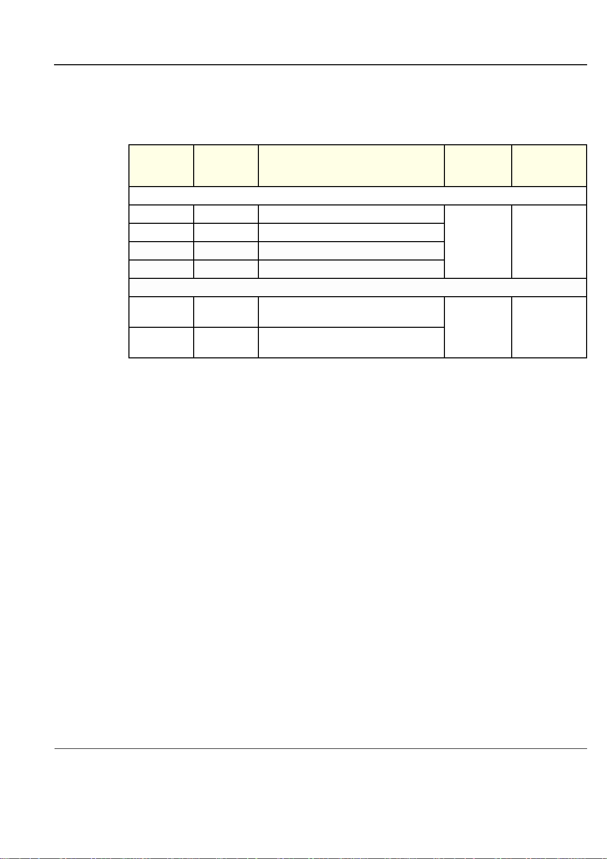
The Vivid™ S5 N and Vivid™ S6 N models documented in this manual are shown in Table 1-2 below.
Table 1-2 Vivid S5 N and Vivid S6 N Models and Hardware/Software Compatibility
MODEL
CAT NO.
Vivid S5 N
H45571WG FN200082
H45571WH FN200083
H45571SH FN000073
H45571SJ FN000074
Vivid S6 N
H45571WF FN000081
H45571SB FN000100
NUMBER DESCRIPTION
Vivid S5 N - 15" LCD - BT12 - 220-240V
Vivid S5 N - 17" LCD - BT12 - 220-240V
Vivid S5 N - 15" LCD - BT12 - 220-240V
Vivid S5 N - 17" LCD - BT12 - 220-240V
Vivid S6 N - 17" LCD - BT12 - 100-240V
Introduced 2013
Vivid S6 N - 17" LCD - BT12 - 220-240V
Introduced 2013
SYSTEM
SOFTWARE
VERSION(s)
v3.0.10 v12.2 Build 53
v3.0.10 v12.2 Build 53
APPLICATION
SOFTWARE
VERSION(s)
Chapter 1 - Introduction 1-3
Page 36

PRELIMINARY
GE
P
ART NUMBER FN091065, REVISION 2 VS5 N AND VS6 N SERVICE MANUAL
1-1-5 Product Description
1-1-5-1 Overview of the Vivid™ S5 N and Vivid™ S6 N Ultrasound system
The Vivid Vivid™ S5 N and Vivid™ S6 N is a compact, phased, linear array ultrasound imaging
scanner.
Weighing only 65 Kgs (144 lbs), each Ultrasound system is extremely versatile and, depending upon
the installed software, can be used for a variety of applications.
The Vivid™ S5 N and Vivid™ S6 N Ultrasound system is based on parallel products in the Vivid family.
Using the same advanced technology, the innovative features and versatility of the system represent
the future of ultrasound scanning.
NOTE: Upgrade op tions may be available with future versions.
NOTE: No upgrade from Vivid S5 N to Vivid S6 N is possible.
1-1-6 Purpose of Operator Manual(s)
The Operator Manual(s) should be fully read and understood before operating the Vivid S5 N or Vivid
S6 N system, and also kept near the unit for quick reference.
1-4 -
Page 37

PRELIMINARY
DANGER
WARNINGWARNING
CAUTION
NOTICE
GE
P
ART NUMBER FN091065, REVISION 2 VS5 N AND VS6 N SERVICE MANUAL
Section 1-2 Important Conventions
1-2-1 Conventions Used in this Manual
1-2-1-1 Model Designations
This manual covers the Vivid™ S5 N and Vivid™ S6 N ultrasound units listed in Table 1- 2 "Vivid S5 N
and Vivid S6 N Models and Hardware/Software Compatibility" on page 1-3.
1-2-1-2 Icons
Pictures, or icons, are used wherever they will reinforce the printed message. The icons, labels and
conventions used on the product and in the service information are described in this chapter.
1-2-1-3 Safety Precaution Messages
Various levels of safety precaution messages may be found on the equipment and in the service
information. The different levels of concern are identi fied by a flag word that precedes the precautionary
message. Known or potential hazards to personal are labeled in one of three ways:
•DANGER
• WARNING
•CAUTION
When a hazard is present that can cause pr ope rty damag e, but ha s absolu tely no pe rsonal in jur y risk,
a NOTICE is used.
DANGER IS USED TO INDICATE THE PRESENCE OF A HAZARD THAT WILL
CAUSE SEVERE PERSONAL INJURY OR DEATH IF THE INSTRUCTIONS ARE
IGNORED.
WARNING IS USED TO INDICATE THE PRESENCE OF A HAZARD THAT CAN CAUSE
SEVERE PERSONAL INJURY AND PROPERTY DAMAGE IF INSTRUCTIONS ARE
IGNORED.
CAUTION IS USED TO INDICATE THE PRESENCE OF A HAZARD THAT WILL OR CAN CAUSE
MINOR PERSONAL INJURY AND PROPERTY DAMAGE IF INSTRUCTIONS ARE IGNORED.
EQUIPMENT DAMAGE POSSIBLE.
Notice is used when a hazard is present that can cause property damage but has absolutely no
personal injury risk.
Example: Disk drive may crash.
NOTE: Notes are used to provide important information about an item or a procedure.
NOTE: Be sure to read the notes as the information they contain can often save you time or effort.
Chapter 1 - Introduction 1-5
Page 38
PRELIMINARY
LASER
LIGHT
Signed
Date
TAG
&
LOCKOUT
OR
GE
P
ART NUMBER FN091065, REVISION 2 VS5 N AND VS6 N SERVICE MANUAL
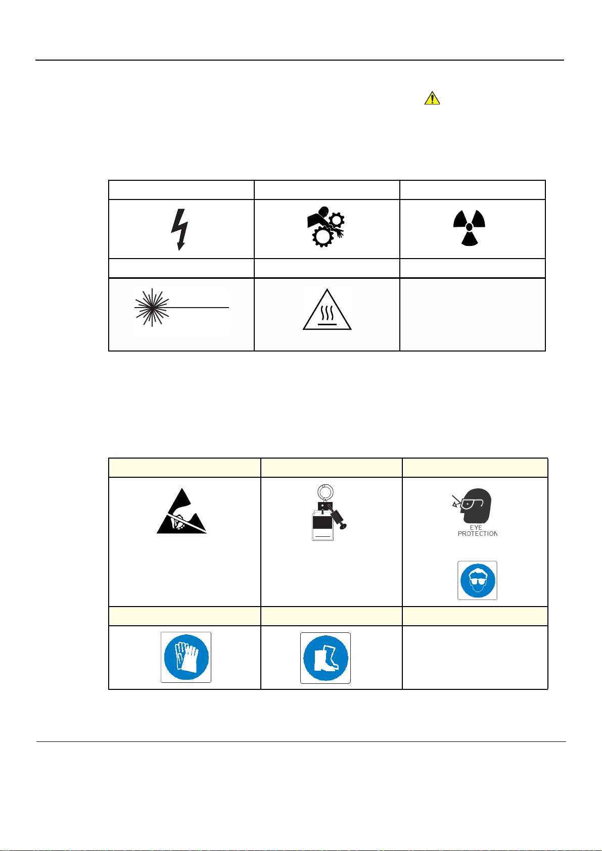
1-2-1-4 Standard Hazard Icons
Important information will always be preceded by the exclamation point contained within a triangle,
as seen throughout this chapter. In addition to text, several different graphical icons (symbols) may be
used to make you aware of specific types of hazards that could possibly cause harm. Even if a symbol
isn’t used in this manual, it may be included for your reference.
Table 1-3 Standard hazard icons
ELECTRICAL MECHANICAL RADIATION
LASER HEAT
Some others icons make you aware of specific procedures that should be followed.
NOTE: The Vivid Vivid S5 N / Vivid S6 N system has no unintended or motorized moving parts that
could cause pinching; all moving parts are mechanically o perated by the user. Pay attention to
move such parts carefully (e.g. LCD arm).
Table 1-4 Standard Icons that indicates that a special procedure is to be used
AVOID STATIC ELECTRICITY TAG AND LOCK OUT WEAR EYE PROTECTION
HAND PROTECTION FOOT PROTECTION
1-6 Section 1-2 - Important Conventions
Page 39
PRELIMINARY
DANGER
WARNINGWARNING
WARNINGWARNING
WARNINGWARNING
WARNINGWARNING
WARNINGWARNING
GE
P
ART NUMBER FN091065, REVISION 2 VS5 N AND VS6 N SERVICE MANUAL
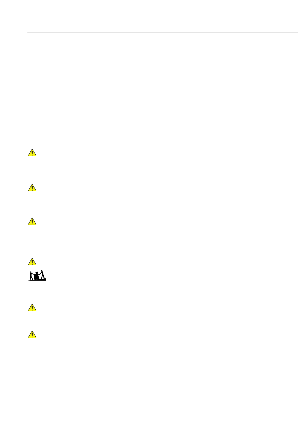
Section 1-3 Safety Considerations
1-3-1 Introduction
The following safety precautions must be observed duri ng all phases of operation, service and repair of
this equipment. Failure to comply with these precautions or with specific warnings elsewhere in this
manual, violates safety standards of design, manufacture and intended use of the equipment.
1-3-2 Human Safety
• Operating personnel must not remove the system covers.
• Servicing should be performed by authorized personnel only.
• Only personnel who have participated in a Vivid S5 N and Vivid S6 N Training Seminar are
authorized to service the equipment.
• Local laws may restrict this device for sale or use by or on the order of a physician.
DANGEROUS VOLTAGES, CAPABLE OF CAUSING DEATH, ARE PRESENT IN
THIS EQUIPMENT. USE EXTREME CAUTION WHEN HANDLING, TESTING AND
ADJUSTING.
IF THE COVERS ARE REMOVED FROM AN OPERATING Vivid S5 N and Vivid S6 N,
SOME METAL SURFACES MAY BE WARM ENOUGH TO POSE A POTENTIAL HEAT
HAZARD IF TOUCHED, EVEN WHILE IN SHUT DOWN MODE.
BECAUSE OF THE LIMITED ACCESS TO CABINETS AND EQUIPMENT IN THE FIELD,
PLACING PEOPLE IN AWKWARD POSITIONS, GE HAS LIMITED THE LIFTING WEIGHT
FOR ONE PERSON IN THE FIELD TO 16 KG (35 LBS). ANYTHING OVER 16 KG (35 LBS)
REQUIRES 2 PEOPLE.
HAVE TWO PEOPLE AVAILABLE TO DELIVER AND UNPACK THE Vivid S5 N and Vivid
S6 N.
ATTEMPTS TO MOVE THE UNIT CONSIDERABLE DISTANCES OR ON AN INCLINE BY
ONE PERSON COULD RESULT IN INJURY OR DAMAGE OR BOTH.
USE ALL PERSONAL PROTECTION EQUIPMENT (PPE) SUCH AS GLOVES, SAFETY
SHOES, SAFETY GLASSES, AND KNEELING PAD, TO REDUCE THE RISK OF INJUR Y.
EXPLOSION WARNING
DO NOT OPERATE THE EQUIPMENT IN AN EXPLOSIVE ATMOSPHERE. OPERATION
OF ANY ELECTRICAL EQUIPMENT IN SUCH AN ENVIRONMENT CONSTITUTES A
DEFINITE SAFETY HAZARD.
Chapter 1 - Introduction 1-7
Page 40
PRELIMINARY
WARNINGWARNING
WARNINGWARNING
CAUTION
CAUTION
CAUTION
GE
P
ART NUMBER FN091065, REVISION 2 VS5 N AND VS6 N SERVICE MANUAL
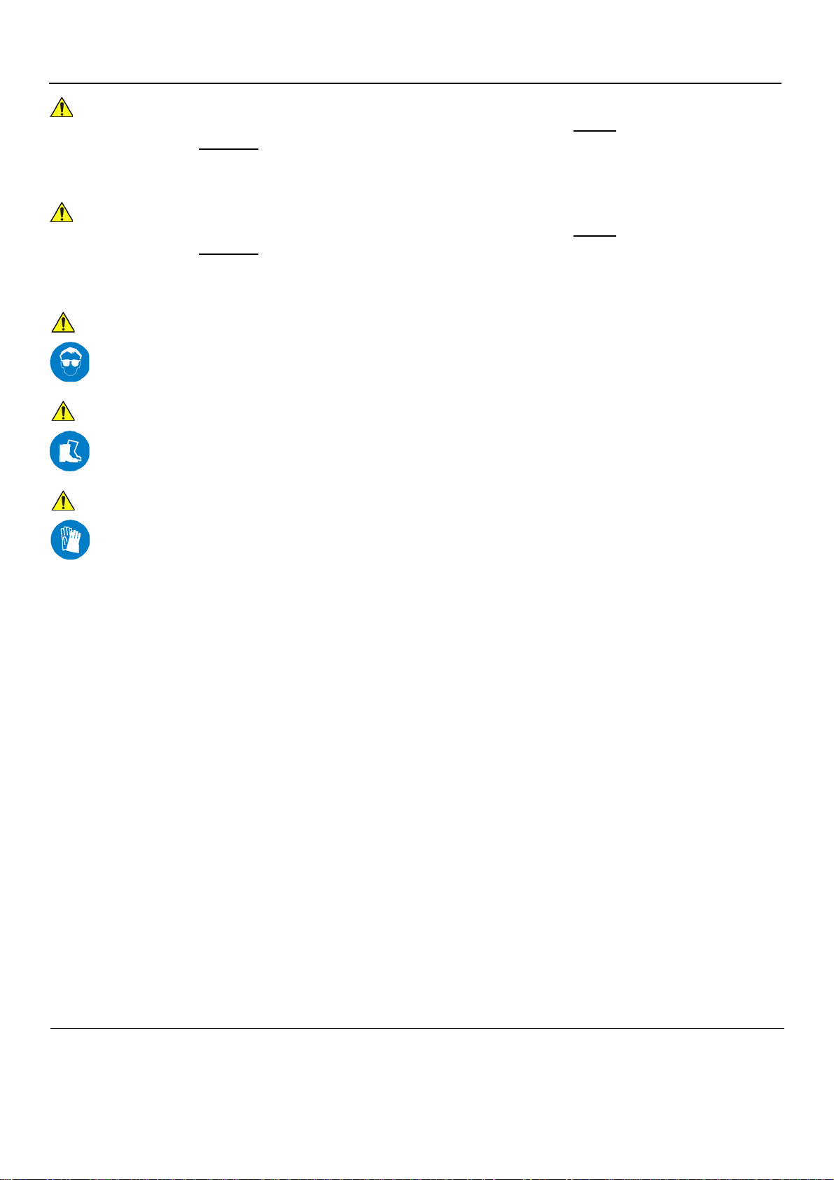
DO NOT SUBSTITUTE PARTS OR MODIFY EQUIPMENT
Because of the danger of introducing additional hazards, ONLY
parts. DO NOT
perform any unauthorized modification of the equipment.
DO NOT SUBSTITUTE PARTS OR MODIFY EQUIPMENT
Because of the danger of introducing additional hazards, ONLY
parts. DO NOT
USE PROTECTIVE GLASSES DURING DRILLING, FILING AND DURING ALL OTHER WORK
WHERE EYES NEED PROTECTION.
USE SAFETY SHOES WHEN DOING WORK WHERE THERE IS ANY CHANCE OF FOOT
DAMAGE.
perform any unauthorized modification of the equipment.
install GE approved
install GE approved
USE PROTECTIVE GLOVES WHEN DRILLING AND CUTTING.
1-8 Section 1-3 - Safety Considerations
Page 41
PRELIMINARY
WARNINGWARNING
WARNINGWARNING
DANGER
DANGER
DANGER
CAUTION
WARNINGWARNING
WARNINGWARNING
GE
P
ART NUMBER FN091065, REVISION 2 VS5 N AND VS6 N SERVICE MANUAL
1-3-3 Mechanical Safety
WHILE THE SOFTWARE INSTALL PROCEDURE IS DESIGNED TO PRESERVE DATA,
YOU SHOULD SAVE ANY PATIENT DATA, IMAGES, SYSTEM SETUPS TO A DVD OR
HARDCOPY BEFORE DOING A SOFTWARE UPGRADE.
PRIOR TO ELEVATING SCANNER, VERIFY THAT THE KEYBOARD IS LOCKED IN ITS
LOWEST POSITION. VERIFY THAT THE FRONT BRAKE IS LOCKED AND THE
SCANNER IS UNABLE TO SWIVEL. VERIFY THAT THE REAR BRAKES ARE IN THE
LOCKED POSITION.
WHENENVER THE UNIT IS TO BE MOVED ALONG ANY INCLINE, USE EXTREME
CAUTION. MAKE SURE THAT THE VIVID S5 N OR VIVID S6 N SCANNER AND ALL
PERIPHERALS ARE SECURELY MOUNTED IN PLACE BEFORE ATTEMPTING TO MOVE
IT.
ULTRASOUND PROBES ARE HIGHLY SENSITIVE MEDICAL INSTRUMENTS THAT CAN
EASILY BE DAMAGED BY IMPROPER HANDLING. USE CARE WHEN HANDLING AND
PROTECT FROM DAMAGE WHEN NOT IN USE. DO NOT USE A DAMAGED OR
DEFECTIVE PROBE. FAILURE TO FOLLOW THESE PRECAUTIONS CAN RESULT IN
SERIOUS INJURY AND EQUIPMENT DAMAGE.
NEVER USE A PROBE THAT HAS BEEN SUBJECTED TO MECHANICAL SHOCK OR
IMPACT. EVEN IF THE PROBE APPEARS TO BE UNBROKEN, IT MAY IN FACT BE
DAMAGED.
THE Vivid S5 N or Vivid S6 N portable ultrasound scanner WEIGHS 65KG (144 L BS.) OR MORE,
DEPENDING ON CARRY-ON PERIPHERALS WHEN READY FOR USE.
Care must be used when moving the unit or replacing its part s. Failure to follow the precautions
listed could result in injury, uncontrolled motion and costly damage.
ALWAYS:
• Use two people when moving on inclines or lifting more than 16 kg (35 lbs)
• Use the handle to move the system
• Be sure the pathway is clear.
• Use slow, careful motions.
• Do not let the system strike walls or door frames.
• When moving the system on inclines, make sure that the Vivid™ S5 N and Vivid™ S6 N scanner and all peripherals are securely
mounted in place before attempting to move the scanner.
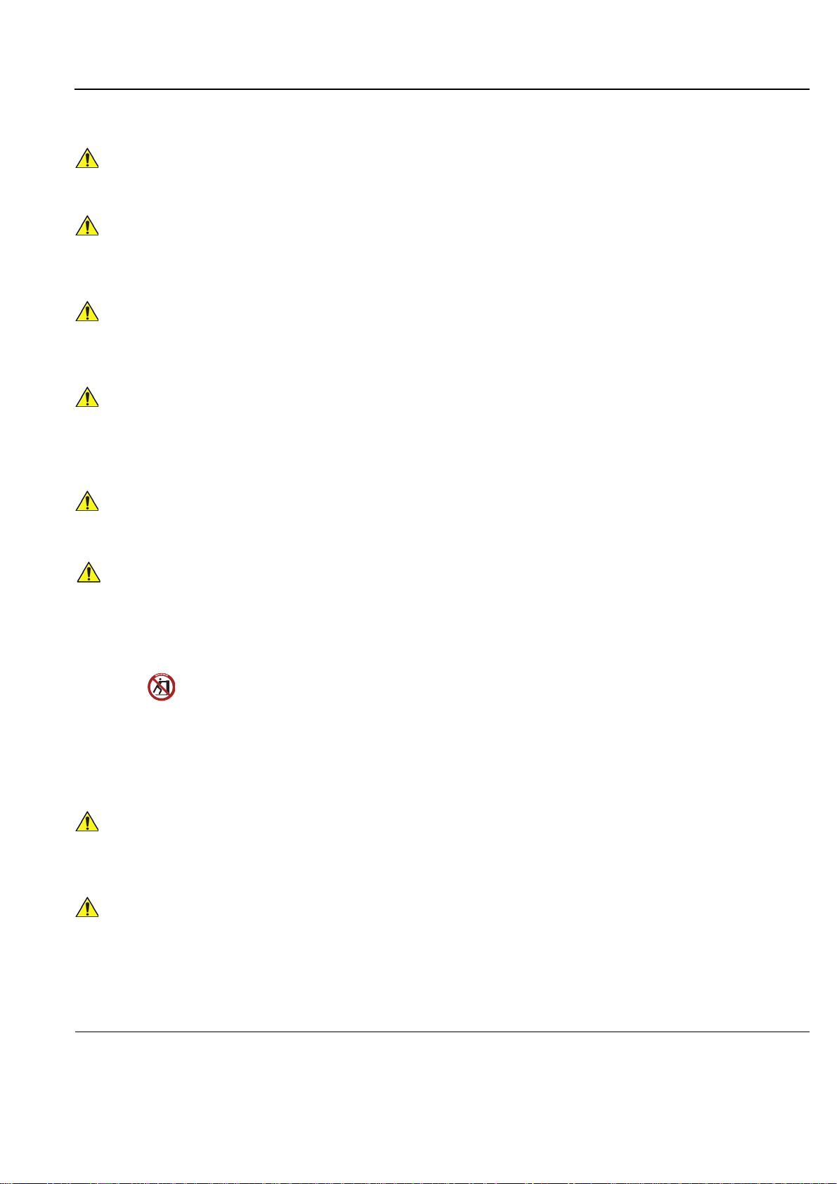
• The rear handle should only be used for pushing the system. Do NOT use it for pulling the ultrasound scanner (in any direction)
as this may cause the system to become unstable in the event of colliding with obstacles.
THE SYSTEM SHOULD NOT BE MOVED WITH THE OPERATING PANEL EXTENDED.
POSITION THE OPERATING PANEL IN ITS CENTERED AND LOCKED POSITION.
LOWER THE OPERATING PANEL AS MUCH AS POSSIBLE BEFORE MOVING THE
SYSTEM.
REMEMBER: IF THE FRONT CASTER SWIVEL LOCK IS ENGAGED FOR
TRANSPORTATION, PRESSING THE RELEASE PEDAL ONCE DISENGAGES THE
SWIVEL LOCK. YOU MUST DEPRESS THE RELEASE PEDAL A SECOND TIME TO
ENGAGE THE BRAKE.
Chapter 1 - Introduction 1-9
Page 42

PRELIMINARY
CAUTION
CAUTION
CAUTION
CAUTION
CAUTION
CAUTION
WARNINGWARNING
WARNINGWARNING
WARNINGWARNING
WARNINGWARNING
GE
P
ART NUMBER FN091065, REVISION 2 VS5 N AND VS6 N SERVICE MANUAL
1-3-3 Mechanical Safety (cont’d)
Before you move or transport the system, make sur e to lock the LCD monitor arm firmly and flip
down the monitor to prevent damage to the system.
Always lock the system in its parked (lock ed) position after moving. Failure to do so could result
in personal injury or equipment damage.
To avoid injury when you move the LCD monitor and the monitor arm, do not put your finger,
hand, or object on the joint of the monitor or the monitor arm.
Ensure that no-one touches the console arm/frogleg when moving the operator panel.
Do not move the unit if the operator panel is in unlocked position.
Keep the heat venting holes on the monitor unobstructed to avoid overheating of the monitor.
THE SYSTEM SHOULD NOT BE MOVED WITH THE OPERATING PANEL EXTENDED.
POSITION THE OPERATING PANEL IN ITS CENTERED AND LOCKED POSITION.
LOWER THE OPERATING PANEL AS MUCH AS POSSIBLE BEFORE MOVING THE
SYSTEM.
Do not transport the Vivid S5 N or Vivid S6 N system in a vehicle without locking the
casters (wheels) and securing it as described in Section 3-8 "Storing an d Transporting
the Unit" on page 3-186.
Equipment damage could result if special care is not taken when transporting the
Vivid™ S5 N and Vivid™ S6 N system in a vehicle.
ALWAYS:
• Eject any media from the media storage devices DVD, MOD (if installed).
• Ensure that monitor is in folded and locked position.
• Ensure that the Vivid™ S5 N and Vivid™ S6 N system is well prepared and packed in its
original packaging before transporting. Special care must b e taken to correctly positio n the
packing material, using all screws and brackets.
For further information, refer to Chapter 3 - System Setup.
• Place the probes in their carrying case.
• Secure the system in an full down position and lock the wheels (brake).
• Ensure that the Vivid™ S5 N and Vivid™ S6 N system is firmly secured while inside the
vehicle.
• Secure the system with straps or as directed otherwise to pre vent motion during transport.
• Prevent vibration damage by driving cautiously . Avoid unpaved roads, excessive speeds,
and erratic stops or starts.
Always lock the system in its parked (locked) position after moving. Failure to do so
could result in personal injury or equipment damage.
1-10 Section 1-3 - Safety Considerations
Page 43

PRELIMINARY
WARNINGWARNING
GE
P
ART NUMBER FN091065, REVISION 2 VS5 N AND VS6 N SERVICE MANUAL
1-3-4 Electrical Safety
To minimize shock hazard, the equipment must be connected to a well grounded power source. The
system is equipped with a three-conductor AC power cable. This must be plugged into an approved
electrical outlet with safety grounding.
To ensure proper grounding, connect this equipment to a receptacle marked “HOSPITAL ONLY” OR
“HOSPITAL GRADE”.
The power outlet used for this equipment should not be shared with other types of eq uipment. Both the
system power cable and the power connector must meet international electrical standards.
Connecting a Vivid™ S5 N and Vivid™ S6 N scanner to the wrong voltage level will
most likely destroy it.
1-3-4-1 Probes
All the probes for the Vivid™ S5 N and Vivid™ S6 N ultrasound unit are design ed and manufactured to
provide trouble-free, reliable service. To ensure this, correct handling of probes is important and the
following points should be noted:
• Do not drop a probe or strike it against a hard surface, as this may damage the transducer elements,
acoustic lens, or housing.
• Do not use a cracked or damaged probe. In this event, call your field service representative
immediately to obtain a replacement.
• Avoid pulling, pinching or kinking the probe cable, since a damaged cable may compromise the
electrical safety of the probe.
• To avoid the risk of a probe accidentally falling, do not allow the probe cables to become entangled,
or to be caught in the system’s wheels.
Follow these guidelines before connecting a probe to the scanner:
• Inspect the probe prior to each use for damage or degradation to the:
•housing
• cable strain relief
• lens
•seal
• connector pins
• locking mechanism
• Do not use a damaged or defective probe.
• Never immerse the probe connector or adapter into any liquid.
• The system has more than one type of probe port. Use th e appropriate probe por t designed for the
probe you are connecting.
NOTE: For detailed information on handling endocavity probes, refer to the appropriate supplementary
instructions for each probe. In addition, refer to the Vivid S5 N or Vivid S6 N User Manual for detailed
probe handling instructions.
Chapter 1 - Introduction 1-11
Page 44
PRELIMINARY
WARNINGWARNING
WARNINGWARNING
GE
P
ART NUMBER FN091065, REVISION 2 VS5 N AND VS6 N SERVICE MANUAL
1-3-4-2 Peripherals
Safety and Environmental Guidelines
Environmental Dangers
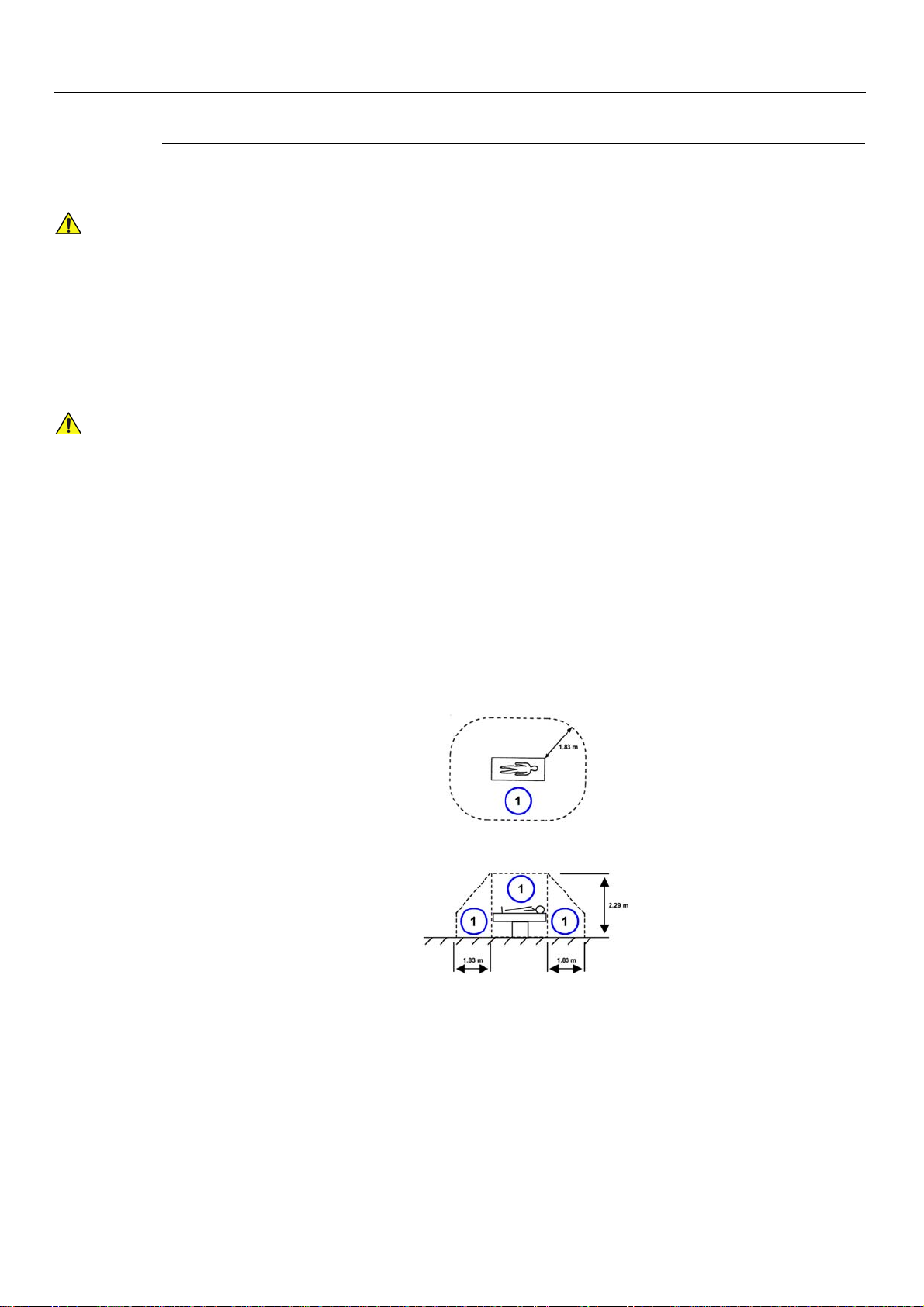
All devices meeting IEC60950 must be kept outside the patient environment as defined
in IEC60601-1-1, unless the devices, according to IEC60601-1-1, are equipped with the
following:
A) Additional Earth Protection
or:
B) An Extra Isolating Transformer
Commercial devices such as laser cameras, printers, VCRs and external monitors,
usually exceed allowable leakage current limits and, when plugged into separate AC
outlets, are in violation of patient safety standards. Suitable electrical isolation of such
external AC outlets, or the provision of extra protective earth for the device, is required
in order to meet UL60601-1 and IEC60601-1-1 standards for electrical leakage.
• Patient Vicinity UL60601-1 (USA)
2.12.20DV (UL60601-1:2003)
In area in which patients are normally cared for, the patient vicinity is the space with surfaces
likely to be contacted by the patient or attendant who can touch the patient. This encloses a
space within the room 1.83 m (6 ft.) beyond the perimeter of the bed (examination table, dental
chair, treatment booth, and the like) in its intended location, and extending vertically 2.29 m
(7.5 ft.) above the floor.
1. Patient environment
1-12 Section 1-3 - Safety Considerations
Page 45
PRELIMINARY
CAUTION
1
GE
P
ART NUMBER FN091065, REVISION 2 VS5 N AND VS6 N SERVICE MANUAL
• Patient Environment IEC60601-1 (IEC60601-1-1) and ANSI AAMI ES60601-1
Sub Clause 2.202 and figure 201 (IEC60601-1-1:2000)
Sub Clause 3.79 and figure A.9 (IEC60601-1:2005 and ANSI AAMI ES60601-1:2005)
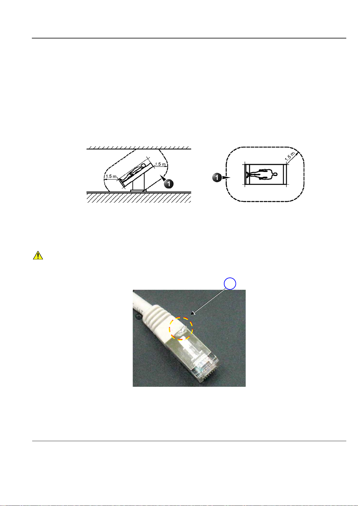
Such an area is an environment in which medical diagnosis, monitoring or treatment is carried
out. It is very difficult to attach unique dimensions to the PATIENT ENVIROMENT.
In practice a distance of 2,5 m (8.2 f t.) above the floo r on which the medical person nel st and and
a horizontal distance of 1,5 m (4.9 f t.) have justified themselves as indica tive of the dimensions of
the Patient Environment.
The patient environment/vicinity will be depicted as a dashed line in this procedure. See example
below.
1 - Patient environment
Figure 1-1 Patient environment
When connecting a peripheral directly to the Vivi d S5 N or Vivid S6 N scanner, if a network cable
(RJ45 LAN) is used, the cable shielding should not be soldered to the LAN connector.
1. Do NOT use a soldered LAN connector when connecting the scann er directly to a peripheral device.
Figure 1-2 Example of Soldered LAN Connector
Chapter 1 - Introduction 1-13
Page 46

PRELIMINARY
CAUTION
WARNINGWARNING
WARNINGWARNING
CAUTION
GE
P
ART NUMBER FN091065, REVISION 2 VS5 N AND VS6 N SERVICE MANUAL
1-3-5 Vivid S5 N / Vivid S6 N Battery Safety
NOTE: The Vivid S6 N ultrasound scann er is supplied with a lithium ion battery in the battery ba y, as standard.
For the Vivid S5 N, it is supplied as an option.
The lithium ion battery provides power to safe ly shutdown the system or place it in Standby mode, when
an AC power source is not available. Lithium ion batteries last longer than conventional batteries and
do not require replacement as often. You ca n ex pect 4 h ours of batte ry life with a sing le, fully-charg ed
battery supporting Standby mode.
The lithium ion technology used in the system’s battery is significantly less hazardous to the
environment than the lithium metal technology used in some other batteries (such a watch batteries).
Used batteries should not be placed with common household waste products. Contact local authorities
for the location of a chemical waste collection program nearest you.
NOTE: Regulations var y for different countries. Dispose of a used battery in accordance with local regula tions.
Use only batteries approved by GE HEALTHCARE as suitable for use with th e Vivid S5 N / Vivid
S6 N ultrasound scanner
THE VIVID S5 N / VIVID S6 N BATTERY HAS A SAFETY DEVICE.
DO NOT ATTEMPT TO DIS-ASSEMBLE OR ALTER THE BATTERY!
ALWAYS OBSERVE THE FOLLOWING PRECAUTIONS:
• Charge batteries only when the ambient temperature is between 0
o
and discharge the batteries between -10
• Do not short-circuit the battery by directly connecting the negative terminals with metal objects.
• Do not heat the battery or discard it in a fire.
• Do not expose the battery to temperatures over 60
other heat sources.
• Do not charge the battery near a heat source, such as, a fire or heater.
• Do not leave the battery in direct sunlight.
• Do not pierce the battery with a sharp object, hit it, or step on it.
• Do not use a damaged battery.
• Do not apply solder to a battery.
• Do not connect the battery to an electrical power outlet.
and 55o C (14o and 131o F)
o
C (140o F). Keep the battery away from fire and
o
and 65o C (32o and 149o F).
In the event that the Vivid S5 N or Vivid S6 N ultrasound scanner will not be used for a
long period, it is recommended to remove the battery from the system while not in use.
To prevent the battery bursting, igniting, or f umes from the batter y causing equipment dama ge,
always observe the following precautions:
• Do not immerse the battery in water or allow it to get wet.
• Do not place the battery into a microwave oven or pressurized container.
• If the battery leaks or emits an odor, remove it from all possible flammable sources.
• If the battery emits an odor or heat, is deformed or discolored, or in a way ap pears abnormal during
use, recharging or storage, immediately remove it and stop using it.
• If you have any questions about the battery, consult your local GE representative.
1-14 Section 1-3 - Safety Considerations
Page 47

PRELIMINARY
WARNINGWARNING
GE
P
ART NUMBER FN091065, REVISION 2 VS5 N AND VS6 N SERVICE MANUAL
1-3-5 Vivid S5 N / Vivid S6 N Battery Safety (cont’d)
• Storage of the battery pack:
o
Short-term (less than 1 month): between 0
Long-term (more than 3 months): between 10
NOTE: When storing a battery pack for more than 6 mo nths, it is necessary to charge the battery pack
at least once every 6 months in order to prevent leakage and deterioration in performance (as
a result of self-discharging).
NOTE: When charging the battery for the first time after long-term stor age, recover the battery pack to
original performance through repeating several cycles of full charging and discharging.
NOTE: When shipped, the Vivid S5 N or Vivid S6 N with the battery it is in a state of being approximately 30% charged.
Before use, it is necessary to fully charge and discharge the battery pack up to 3 times, in order to utilize Li-lon
smart packs.
1-3-6 Patient Data Safety
C (32o F) and 50o C (122o F).
o
C (50o F) and 35o C (95o F)
While the software install procedure is designed to preserve data, you should save any
patient data, images, system setups to a DVD or hardcopy before doing a software
upgrade.
Chapter 1 - Introduction 1-15
Page 48

PRELIMINARY
DANGER
WARNINGWARNING
WARNINGWARNING
WARNINGWARNING
GE
P
ART NUMBER FN091065, REVISION 2 VS5 N AND VS6 N SERVICE MANUAL
1-3-7 Dangerous Procedure Warnings
Warnings, such as the examples below, precede potentially dangerous procedures throughout this
manual. Instructions contained in the warnings must be followed.
DANGEROUS VOLTAGES, CAPABLE OF CAUSING DEATH, ARE PRESENT IN
THIS EQUIPMENT. USE EXTREME CAUTION WHEN HANDLING, TESTING AND
ADJUSTING.
If the covers are removed from an operating Vivid S5 N or Vivid S6 N system, some
metal surfaces may be warm enough to pose a potential heat hazard if touched, even
while in shut down mode.
Explosion Warning
Do not operate the equipment in an explosive atmosphere. Operation of any electrical
equipment in such an environment constitutes a definite safety hazard.
Do not substitute parts or modify equipment
Because of the danger of introducing additional hazards, do not in stall substitute parts or
perform any unauthorized modification of the equipment.
1-16 Section 1-3 - Safety Considerations
Page 49
PRELIMINARY
WARNINGWARNING
Signed
Date
TAG
&
LOCKOUT
GE
P
ART NUMBER FN091065, REVISION 2 VS5 N AND VS6 N SERVICE MANUAL
Section 1-4 Lockout/Tagout (LOTO) requirements
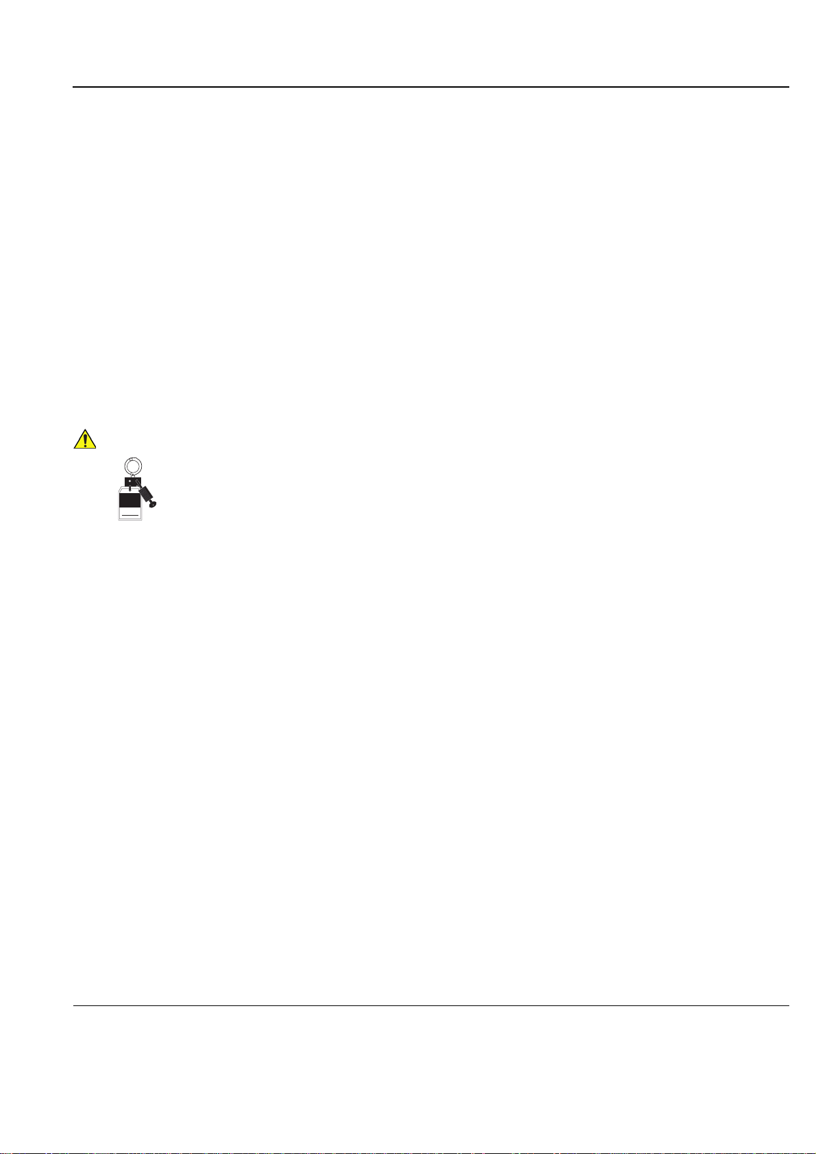
Follow OSHA Lockout/Tagout requirements (USA) or local Lockout/Tagout requirements by ensuring
you are in total control of the AC power plug at all times during the service process. This will protect
service personnel from injuries caused by unexpected energizing or start-up of equipment during
service, repair, or maintenance.
To apply Lockout/Tagout (LOTO):
1.) Plan and prepare for shutdown.
2.) Shutdown the equipment.
3.) Isolate the equipment.
4.) Apply Lockout/Tagout Devices.
5.) Control all stored and residual energy.
6.) Verify isolation.
All potentially hazardous stored or residual energy is relieved.
ENERGY CONTROL AND POWER LOCKOUT FOR Vivid S5 N and Vivid S6 N.
WHEN SERVICING PARTS OF THE SYSTEM WHERE THERE IS EXPOSURE TO
VOLTAGE GREATER THAN 30 VOLTS:
1. FOLLOW LOCK OUT/TAG OUT PROCEDURES.
2. TURN OFF THE BREAKER.
3. UNPLUG THE Vivid S5 N and Vivid S6 N.
4. MAINTAIN CONTROL OF THE POWER PLUG.
5. WAIT FOR AT LEAST 20 SECONDS FOR CAPACITORS TO DISCHARGE, AS THERE ARE NO TEST POINTS TO
VERIFY ISOLATION. THE AMBER LIGHT ON THE OP PANEL ON/OFF BUTTON WILL TURN OFF.
BEWARE THAT THE MAIN POWER SUPPLY AND BACK END PROCESSOR MAY BE ENERGIZED EVEN IF THE POWER
IS TURNED OFF WHEN THE CORD IS STILL PLUGGED INTO THE AC OUTLET.
Chapter 1 - Introduction 1-17
Page 50
PRELIMINARY
GE
P
ART NUMBER FN091065, REVISION 2 VS5 N AND VS6 N SERVICE MANUAL
Section 1-5 Product Labels and Icons
The Vivid S5 N and Vivid S6 N ultrasound scanner comes equipped with product labels and icons.
These labels and icons represent pertinent information regarding the operation of the unit.
1-5-1 Product Labels (Label, General info)
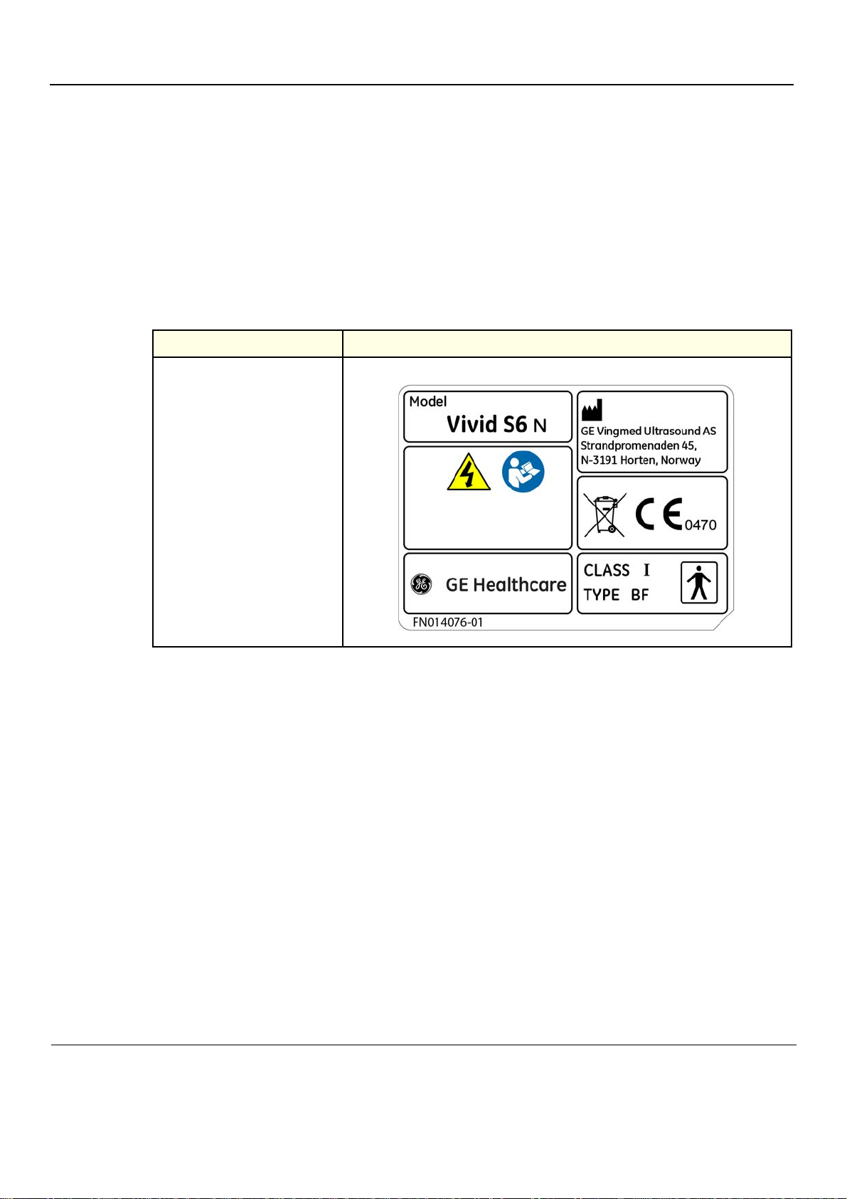
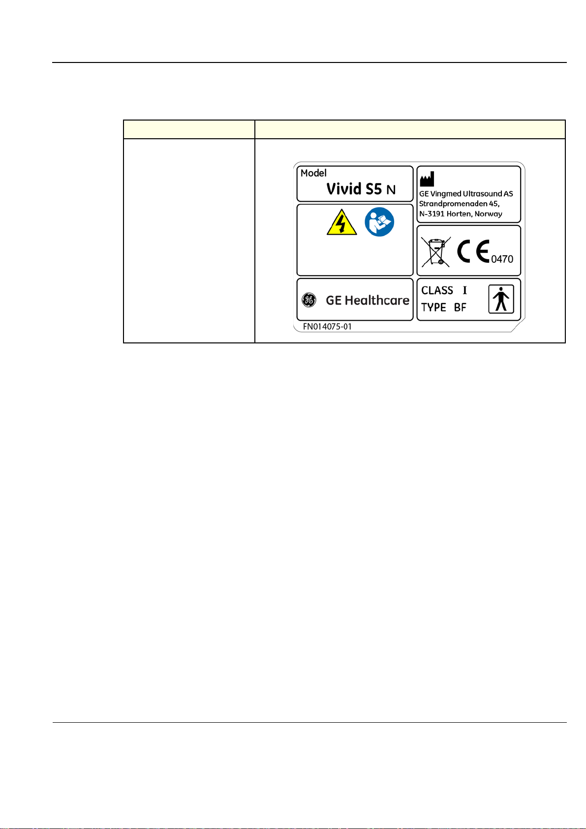
The following tables show the Product Labels (Label, General info) found on the Vivid S5 N / Vivid S6 N
ultrasound units. All the labels and icons are described in Table 1-7 "Product Icons" on page 1-20.
Table 1-5 Product Labels, Vivid S6 N
Description Label
Label, General Info, BT12
1-18 Section 1-5 - Product Labels and Icons
Page 51
PRELIMINARY
GE
P
ART NUMBER FN091065, REVISION 2 VS5 N AND VS6 N SERVICE MANUAL
1-5-1 Product Labels (Label, General info) (cont’d)
Table 1-6 Product Labels, Vivid S5 N
Description Label
Label, General Info, BT12
Chapter 1 - Introduction 1-19
Page 52
PRELIMINARY
GE
P
ART NUMBER FN091065, REVISION 2 VS5 N AND VS6 N SERVICE MANUAL
1-5-2 Label Descriptions and Locations
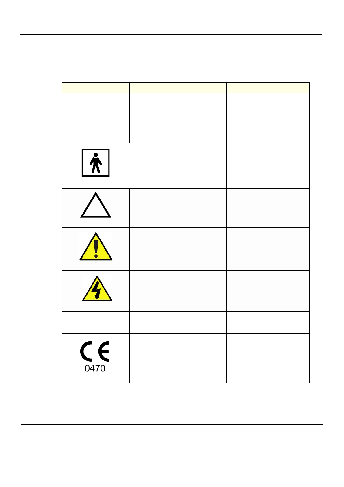
The following table shows the labels and symbols that may be found on th e Vivid S5 N or Vivid S6 N
ultrasound unit, and provides a description of each label’s purpose and location.
Table 1-7 Product Icons
Label Name Description Location
Manufacturer’s name and address.
Identification and Rating Plate
Date of Manufacture.
Model and Serial numbers.
Electrical ratings (Volts, Amps, phase, and
frequency.
Rear of the system.
Type/Class Label
Used to indicate the degree of safety or
protection.
Equipment Type BF (man in the box symbol)
IEC 878-02-03 indicates B Type equipment
having a floating applied part.
“CAUTION” The equilateral triangle is usually
used in combination with other symbols to
advise or warn the user.
“ATTENTION - Consult accompanying
documents” is intended to alert the user to refer
to the User Manual or other instructions when
complete information cannot be provided on
the label.
“CAUTION - Dangerous voltage” (the lightning
flash with arrowhead in equilateral triangle) is
used to indicate electric shock hazards.
Bottom panel of the adapter
Probe connectors.
Various.
Various.
Various.
Device Listing/Certification
Labels
Laboratory logos or labels that denote
conformity with industry safety standards, such
as UL or IEC.
CE certification mark. On the base of the unit
1-20 Section 1-5 - Product Labels and Icons
On the base of the unit
Page 53
PRELIMINARY
GE
P
ART NUMBER FN091065, REVISION 2 VS5 N AND VS6 N SERVICE MANUAL
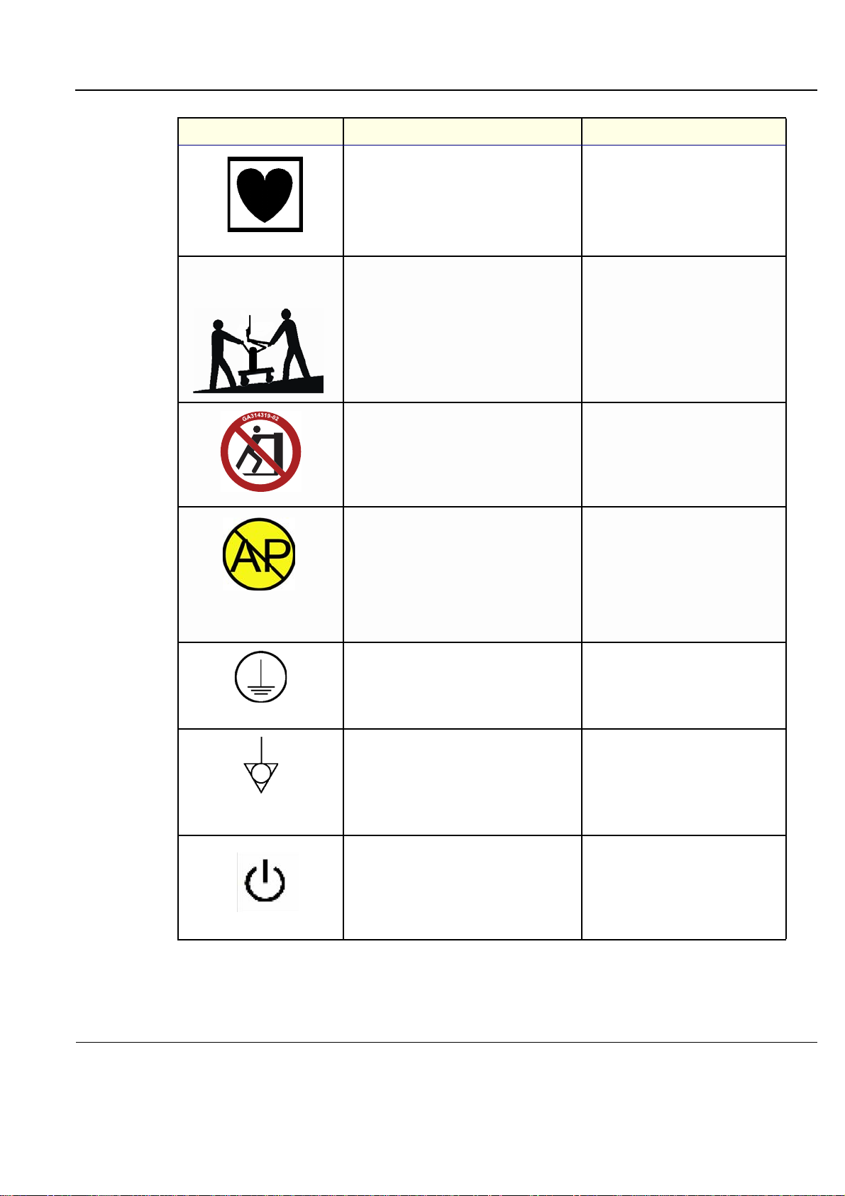
Table 1-7 Product Icons (cont’d)
Label Name Description Location
Equipment Type CF IEC 878-02-05 indicates
Above the ECG inlet, ECG connector
and surgical probes.
Used in the Service and User Manual
which should be adjacent to equipment
at all times for quick reference.
CAUTION - This machine
weighs...Special care must be
used to avoid...
equipment having a floating applied part that
provides a degree of protection suitable for
direct cardiac contact.
This precaution is intended to prevent injury
that may be caused by the weight of the
machine if one person attempts to move it
considerable distances or on an incline.
“DANGER - Risk of explosion
used in...”
Do not push Vivid S5 N and Vivid S6 N
sideways when casters are in break position.
Instability may occur.
The system is not designed for use with
flammable anesthetic gases.
“Protective Earth” Indicates the protective
earth (grounding) terminal.
“Equipotentiality” Indicates the terminal to be
used for connecting equipotential conductors
when interconnecting (grounding) with other
equipment.
Indicated in the Service Manual.
Rear of the system.
Peripherals
“ON” indicates the power ON position of the
power switch. “Standby” indicates the power
stand by position of the power switch.
CAUTION This Power Switch DOES NOT
ISOLATE Mains Supply.
Adjacent to ON/Standby Switch
Chapter 1 - Introduction 1-21
Page 54

PRELIMINARY
GE
P
ART NUMBER FN091065, REVISION 2 VS5 N AND VS6 N SERVICE MANUAL
Table 1-7 Product Icons (cont’d)
Label Name Description Location
Waste Electrical and Electronic Equipment
(WEEE) Disposal
This symbol indicates that waste electrical and
electronic equipment must not be disposed of
as unsorted municipal waste and must be
collected separately.
Please contact an authorized representative of
the manufacturer for information concerning
the decommissioning of your equipment.
On the base of the unit.
On the rear of the system.
1-22 Section 1-5 - Product Labels and Icons
Page 55
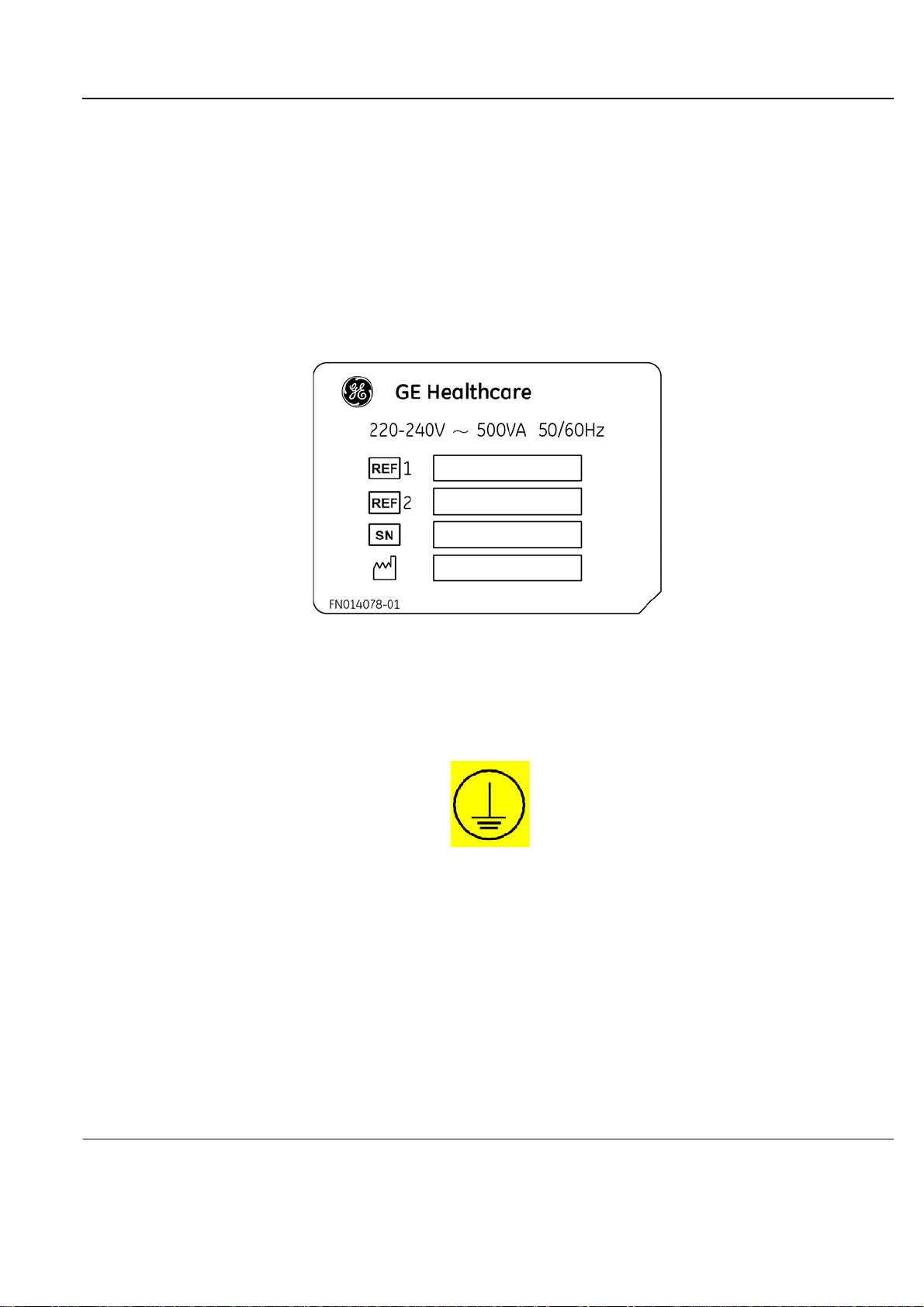
PRELIMINARY
GE
P
ART NUMBER FN091065, REVISION 2 VS5 N AND VS6 N SERVICE MANUAL
1-5-3 Vivid™ S5 N and Vivid™ S6 N External Labels
In addition to the labels described in the previous section, additional labels may be found on the
Vivid S5 N or Vivid S6 N ultrasound unit, as described in the following sections:
• Product Labels section, see below.
• GND Label section, see below.
1-5-3-1 Product Labels
Indicates the ultrasound unit’s basic power compliance and regulatory compliance information
The Product label shown below is located on the base assembly.
1-5-3-2 GND Label
Indicates the protective earth (grounding) terminal. The GND label (shown Figure 1 -4 below) is located
at the rear of the system.
Figure 1-3 Product Label example
Figure 1-4 GND Label
Chapter 1 - Introduction 1-23
Page 56

PRELIMINARY
GE
P
ART NUMBER FN091065, REVISION 2 VS5 N AND VS6 N SERVICE MANUAL
Section 1-6 Returning/Shipping Probes and Repair Parts
Equipment being returned must be clean and free of blood and other in fectious substances.
GE Healtcare policy states that body fluids must be properly removed from any part or equipment prior
to shipment. GE Healtcare employees, as well as customers, are responsible for ensuring that parts/
equipment have been properly decontaminated prior to shipment. Under no circumstance should a part
or equipment with visible body fluids be taken or shipped from a clinic or site (for example, body coils
or an ultrasound probe).
The purpose of the regulation is to protect employees in the transportation industry, as well as the
people who will receive or open this package.
NOTE: The US Department of Transportation (DOT) has ruled that “items that were saturated and/or
dripping with human blood that are now caked with dried blood; or which were used or intended
for use in patient care” are “regulated medical waste” for transportation purpo ses and must be
transported as a hazardous material.
NOTE: The USER/SERVICE staff should dispose of all the waste properly, per federal, state, and local
waste disposal regulations.
The Ultrasound system is not meant to be used for long-term storage of patient data or images. The
user is responsible for the data on the system and a regular backup is highly recommended.
If the system is sent for repair, please ensure that any patient information is backed up and erased from
the system before shipping. It is always possible during system failure and repair to lose patient data.
GE is not responsible for the loss of this data.
If PHI (Patient Healthcare Information) data needs to be sent to GE employees for service purposes,
GE will ascertain agreement from the customer. Patient information shall only be transferred by
approved service processes, tools and devices restricting access, protecting or encrypting data wher e
required, and providing traceability in the form of paper or electronic documents at each stage of the
procedure while maintaining compliance with cross-border restrictions of patient information transfers.
1-24 Section 1-6 - Returning/Shipping Probes and Repair Parts
Page 57
PRELIMINARY
WARNINGWARNING
WARNINGWARNING
CAUTION
GE
P
ART NUMBER FN091065, REVISION 2 VS5 N AND VS6 N SERVICE MANUAL
Section 1-7 EMC, EMI, and ESD
1-7-1 Electromagnetic Compatibility (EMC)
Electromagnetic compatibility describes a level of performance of a device within its electromagnetic
environment. This environment consists of the device itself and its surroundings, including other
equipment, power sources and persons with which the device must interface. Inadequate compatibility
results when a susceptible device fails to perform as intended due to interference from its environment,
or when the device produces unacceptable levels of emission. This interference is often refe rred to as
radio–frequency or electromagnetic interference (RFI/EMI) and can be radiated through space or
conducted over interconnecting power or signal cables. In addition to electromagnetic energy, EMC
also includes possible effects from electrical fields, magnetic fields, electrostatic discharge and
disturbances in the electrical power supply.
1-7-2 CE Compliance
The Vivid S5 N and Vivid S6 N ultrasound scanners conform to all applicable conducted and radiated
emission limits and to immunity from electrostatic discharge, radiated and conducted RF fields,
magnetic fields and power line transient requirements.
For applicable standards refer to the Safety Chapter in the Vivid S5 N or Vivid S6 N User Manual.
NOTE: For CE Compliance, it is critical that all covers, screws, shielding, gaskets, mesh and clamps are in good
condition and installed tightly without skew or stress. Proper installation following all comments noted
in this service manual is required in order to achieve full EMC performance.
1-7-3 Electrostatic Discharge (ESD) Prevention
DO NOT TOUCH ANY BOARDS WITH INTEGRATED CIRCUITS PRIOR TO TAKING THE
NECESSARY ESD PRECAUTIONS.
1. ALWAYS CONNECT YOURSELF, VIA AN ARM-WRIST STRAP, TO THE ADVISED
ESD CONNECTION POINT LOCATED ON THE REAR OF THE SCANNER (NEAR THE
POWER CONNECTOR).
2. FOLLOW GENERAL GUIDELINES FOR HANDLING OF ELECTROSTATIC SENSITIVE
EQUIPMENT.
RISK OF ELECTRICAL SHOCK, SYSTEM MUST BE TURNED OFF. AVOID ALL
CONTACT WITH ELECTRICAL CONTACTS, CONDUCTORS AND COMPONENTS.
ALWAYS USE NON-CONDUCTIVE HANDLES DESIGNED FOR THE REMOVAL AND
REPLACEMENT OF ESD SENSITIVE PARTS. ALL PARTS THAT HAVE THE POTENTIAL
FOR STORING ENERGY MUST BE DISCHARGED OR ISOLATED BEFORE MAKING
CONTACT.
1-7-4 General Caution
Any changes to accessories, peripheral units or any other part of t he system must be approved
by the manufacturer. Ignoring this advice may compromise the regulatory approvals obtained
for the product.
Chapter 1 - Introduction 1-25
Page 58

PRELIMINARY
GE
P
ART NUMBER FN091065, REVISION 2 VS5 N AND VS6 N SERVICE MANUAL
Equipment being returned must be clean and free of blood and other in fectious substances.
GE Healtcare policy states that body fluids must be properly removed from any part or equipment prior
to shipment. GE Healtcare employees, as well as customers, are responsible for ensuring that parts/
equipment have been properly decontaminated prior to shipment. Under no circumstance should a part
or equipment with visible body fluids be taken or shipped from a clinic or site (for example, body coils
or an ultrasound probe).
The purpose of the regulation is to protect employees in the transportation industry, as well as the
people who will receive or open this package.
NOTE: The US Department of Transportation (DOT) has ruled that “items that were saturated and/or
dripping with human blood that are now caked with dried blood; or which were used or intended
for use in patient care” are “regulated medical waste” for transportation purpo ses and must be
transported as a hazardous material.
NOTE: The USER/SERVICE staff should dispose of all the waste properly, per federal, state, and local
waste disposal regulations.
The Ultrasound system is not meant to be used for long-term storage of patient data or images. The
user is responsible for the data on the system and a regular backup is highly recommended.
If the system is sent for repair, please ensure that any patient information is backed up and erased from
the system before shipping. It is always possible during system failure and repair to lose patient data.
GE is not responsible for the loss of this data.
If PHI (Patient Healthcare Information) data needs to be sent to GE employees for service purposes,
GE will ascertain agreement from the customer. Patient information shall only be transferred by
approved service processes, tools and devices restricting access, protecting or encrypting data wher e
required, and providing traceability in the form of paper or electronic documents at each stage of the
procedure while maintaining compliance with cross-border restrictions of patient information transfers.
1-26 Section 1-7 - EMC, EMI, and ESD
Page 59

PRELIMINARY
GE
P
ART NUMBER FN091065, REVISION 2 VS5 N AND VS6 N SERVICE MANUAL
Section 1-8 Customer Assistance
1-8-1 Contact Information
If this equipment does not work as indicated in this service manual or in the user manual, or if you
require additional assistance, please contact the local distributor or appropriate support resource, as
listed below.
Before you call, identify the following information, and acquire image (Alt+D) to send to the Customer
Care team:
• System ID serial number.
• Software version.
• Date and time of occurrence.
• Sequence of events leading to issue.
• Is the issue repeatable?
• Imaging mode, probe, preset/application.
• Media brand, speed, capacity, type.
• Save secondary image capture, cine loop, 4D multi-volume loop.
• Detailed description of any problem encountered.
• Where applicable, save the appropriate log files. Remember to save the log files for each day on a
separate media, labelled accordingly.
Restart the application before resuming clinical scanning.
Chapter 1 - Introduction 1-27
Page 60
PRELIMINARY
GE
P
ART NUMBER FN091065, REVISION 2 VS5 N AND VS6 N SERVICE MANUAL
Table 1-8 Phone numbers for Customer Assistance
1-28 Section 1-8 - Customer Assistance
Page 61

PRELIMINARY
GE
P
ART NUMBER FN091065, REVISION 2 VS5 N AND VS6 N SERVICE MANUAL
1-8-2 System manufacturer
Table 1-9 System manufacturer
MANUFACTURER PHONE NUMBER FAX NUMBER
GE VINGMED ULTRASOUND A/S
STRANDPROMENADEN 45
P.O. BOX 141
NO-3191 HORTEN
NORWAY
+47 3302 1100 +47 3302 1350
Chapter 1 - Introduction 1-29
Page 62

PRELIMINARY
GE
P
ART NUMBER FN091065, REVISION 2 VS5 N AND VS6 N SERVICE MANUAL
This page was intentionally left blank.
1-30 Section 1-8 - Customer Assistance
Page 63
PRELIMINARY
GE
P
ART NUMBER FN091065, REVISION 2 VS5 N AND VS6 N SERVICE MANUAL
Chapter 2
Site Preparations
Section 2-1 Overview
2-1-1 Purpose of Chapter 2
This chapter provides the information required to plan and p repare for the installation of a Vivid S5 N or
Vivid S6 N ultrasound unit. Included are descriptions of the electrical and facility requirements that must
be met by the purchaser. A worksheet is provided at th e en d of this cha p te r (refe r to Figure 2-2 on
page 2-11) to help ensure that all the required network information is available, prior to installation.
Table 2-1 Contents in Chapter 2
Section Description Page Number
2-1
2-2
2-3
Overview
Console Requirements
Facility Needs
2-1
2-2
2-7
Chapter 2 - Site Preparations 2-1
Page 64
PRELIMINARY
CAUTION
GE
P
ART NUMBER FN091065, REVISION 2 VS5 N AND VS6 N SERVICE MANUAL
Section 2-2 Console Requirements
2-2-1 Unit Environmental Requirements
Table 2-2 Environmental Requirements
Relative Humidity
Requirement Temperature
(non-condensing)
Air Pressure
Operational
Storage
Transport
10 — 40
-20 — 60
-20 — 60
o
C (50 — 104oF)
o
C (-4 — 140oF)
o
C (-4 — 140oF)
30 — 85%
30 — 70%
30 — 70%
700 — 1060 hPa
700 — 1060 hPa
700 — 1060 hPa
NOTE: The Vivid™ S5 N and Vivid™ S6 N system may be operated at an altitude of up to 300 0 meters
(9842 ft)
If the system has been in storage or has been transported, please see the acclimation
requirements before powering
ON and/or using the system. 3-2-2 "Installation Warnings" on
page 3-2.
NOTE: After a long period of storage, or after transportation of the system with the monitor in the folded-down
position, it is highly recommended to place the monitor in the upright position - and to leave it in this
position for a period of longer than 1 hour before use. This will enable it to properly adjust to the
environmental conditions.
2-2-2 Cooling Requirements
The cooling requirement for the Vivid S5 N or Vivid S6 N ultr asound unit environment is 3500 BTU/hr.
This figure does not include the cooling required for lights, people, or other equipment in the room.
NOTE: Each person in the room places an additional 300 BTU/hr demand on the environmental
cooling.
2-2-3 Lighting Requirements
For system installation, updates and repairs, bright lighting is required. However, operator and patient
comfort may be optimized if the room lighting is subdued and indirect when a scan is being per formed.
Therefore, a combination lighting system (dim/bright) is recommended. Keep in mind that monitor
lighting can be adjusted automatically on the Vivid S6 N if this option is used.
2-2 Section 2-2 - Console Requirements
Page 65

PRELIMINARY
CAUTION
GE
P
ART NUMBER FN091065, REVISION 2 VS5 N AND VS6 N SERVICE MANUAL
2-2-4 Time and Manpower Requirements
Site preparation takes time. Begin pre-installation checks as soon as possible to allow sufficient time to
make any required changes. If possible, begin these checks as many as six weeks before system
delivery.
Only one person is required to unpack the Vivid S5 N or Vivid S6 N ultrasound unit; at least two
people must be available to roll the system down the wheeling ramp. Attempts to move the system
considerable distances (or on an incline) by one person alone, could result in personal injury, and/
or damage to the system.
Chapter 2 - Site Preparations 2-3
Page 66
PRELIMINARY
GE
P
ART NUMBER FN091065, REVISION 2 VS5 N AND VS6 N SERVICE MANUAL
2-2-5 Electrical Requirements
NOTE: GE HEALTHCARE requir es a dedicated mains power line and Gr ound for the proper operation
of its Ultrasound equipment. This dedicated power line shall originate at the last distribution
panel before the system.
Sites with a mains power system with defined Neutral and Live:
The dedicated line shall consist of one phase, a neutral (not shared with any other circuit), and a full
size Ground wire from the distribution panel to the Ultrasound outlet.
Sites with a mains power system without a defined Neutral:
The dedicated line shall consist of one phase (two lines), not shared with any other circuit, and a full
size Ground wire from the distribution panel to the Ultrasound outlet.
NOTE: Please note that image artifacts can occur, if at any time within the facility, the Ground from the
main facility's incoming power source to the Ultrasound unit is only a conduit.
2-2-5-1 Vivid™ S5 N and Vivid™ S6 N Power Requirements
Electrical specifications for the Vivid™ S5 N and Vivid™ S6 N sys tem ar e as follows:
Table 2-3 Electrical Requirements
Input Voltage Tolerances Op. Current Frequency
100V AC to 240V AC ±10% 0.5 to 1A 50-60 Hz
2-2-5-2 Inrush Current
Inrush current is not a factor for consideration, due to the inrush current limiting prop erties of the power
supplies.
Table 2-4 Inrush Current
Voltage
240 V 2.3 A 4.5 A
2-2-5-3 Site Power Outlets
A dedicated AC power outlet must be within reach of the unit without requiring the use of extension
cords. Other outlets adequate for the external peripherals, medical and test equipment required to
support this unit must also be present and located within 1 m (3.2 ft) of the unit. Two dedicated outle ts
for peripherals - located at the rear of the system - should be used for all peripherals attached to the
system, unless otherwise indicated. Electrical installation must meet all current local, state, and national
electrical codes.
Inrush Current
Console Only Console with all Peripherals
2-2-5-4 Mains Power Plug
The Vivid™ S5 N and Vivid™ S6 N portable ultrasound scanner is supplied with a mains power plug,
as standard. In the event that the unit arrives without a power plug, or with the wrong plu g, contact your
GE dealer. When necessary, the installation engineer will supply the appropriate power plug to meet
the applicable local regulations.
2-4 Section 2-2 - Console Requirements
Page 67

PRELIMINARY
GE
P
ART NUMBER FN091065, REVISION 2 VS5 N AND VS6 N SERVICE MANUAL
2-2-5 Electrical Requirements (cont’d)
2-2-5-5 Power Stability Requirements
• Voltage drop-out
Max 10 ms.
• Power Transients
(All applications)
Less than 25% of nominal peak voltage for less than 1 millisecond for any type of transient, including
line frequency, synchronous, asynchronous, or aperiodic transients.
2-2-6 EMI Limitations
Ultrasound machines are susceptible to Electromagnetic Interference (EMI) from radio frequencies,
magnetic fields, and transients in the air or wiring. They also generate EMI. The Vivid™ S5 N and
Vivid™ S6 N ultrasound unit complies with limits as stated on the EMC label. However, there is no
guarantee that interference will not occur in a particular installation.
NOTE: Possible EMI sou rces should be identified before the unit is in stalled, and should not be on the
same line as the ultrasound system. A dedicated line should be used for the ultrasound system.
Electrical and electronic equipment may produce EMI unintentionally as the result of a defe ct. Sources
of EMI include the following:
• Medical lasers.
• Scanners.
• Cauterizing guns.
•Computers.
•Monitors.
•Fans.
• Gel warmers.
• Microwave ovens.
• Portable phones.
• Broadcast stations and mobile broadcasting machines.
Chapter 2 - Site Preparations 2-5
Page 68
PRELIMINARY
GE
P
ART NUMBER FN091065, REVISION 2 VS5 N AND VS6 N SERVICE MANUAL
2-2-6 EMI Limitations (cont’d)
The following table lists recommendations for preventing EMI:
Table 2-5 EMI Prevention/ Abatement
EMI Rule Details
Ground the unit.
Be aware of RF sources.
Replace and/or reassemble
all screws, RF gaskets,
covers and cores.
Replace broken RF gaskets.
Do not place labels where
RF gaskets touch metal.
Use GE-specified harnesses
and peripherals.
Take care with cellular
phones.
Properly address peripheral
cables.
Poor grounding is the most likely reason an ultrasound unit will have noisy images.
Check the grounding of the power cord and power outlet.
Keep the unit at least 5m (16.4 ft) away from other EMI sources. Special shielding may
be required to eliminate interference problems caused by high frequency, high powered
radio or video broadcast signals.
After you finish repairing or updating the system, replace all covers and tighten all
screws. Any cable with an external connection requires a magnet wrap at each end.
Install the shield over the front of the card cage. Loose or missing covers or RF gaskets
allow radio frequencies to interfere with the ultrasound signals.
If more than 20% or a pair of the fingers on an RF gasket are broken, replace the gasket.
Do not turn ON the unit until any loose metallic part is removed and replaced, if required.
Never place a label where RF gaskets meet the unit. Otherwise, the gap created will
permit RF leakage. In case a label has been found in such a location, move the label to
a different, appropriate location.
The interconnect cables are grounded and require ferrite beads and other shielding.
Cable length, material, and routing are all important; do not make any changes that do
not meet all specifications.
Cellular phones may transmit a 5 V/m signal that causes image artifacts.
Do not allow cables to lie across the top of the system. Loop any peripheral cable excess
length into one bundle.
2-2-7 Probe Environmental Requirements
Table 2-6 Probe Operation and Storage Temperatures
Electronics
Operation 10 — 40
Storage -20 — 50oC(-4 — 122oF)
NOTE: System and electro nic probes are designed for storage te mperatures of - 20o to +50o C. When
exposed to large temperature variations, the probes should be kept at room temperatu re for a
minimum of 10 hours before use.
2-6 Section 2-2 - Console Requirements
o
C(50 — 104oF)
Page 69

PRELIMINARY
GE
P
ART NUMBER FN091065, REVISION 2 VS5 N AND VS6 N SERVICE MANUAL
Section 2-3 Facility Needs
2-3-1 Purchaser Responsibilities
The work and materials required to prepare the site are the responsibility of the purchaser. To avoid
delay, complete all pre-installation work before delivery. Use the Pre-installation Check List (provided
in Table 2-7 "Vivid™ S5 N and Vivid™ S6 N Pre-Installation Check List" on page 2-13) to verify that all
the required steps have been completed.
Purchaser responsibilities include:
• Procuring the required materials.
• Completing the preparations prior to delive ry of the ult ra so und sys te m.
• Paying the costs of any alterations and modifi cati ons not specifically provided for in the sales
contract.
NOTE: All relevant preliminary electrical installations at the prepared site must be performed by
licensed electrical contractors. Other connections between electrical equipment, and
calibration and testing, must also be performed by qualified personnel. The products involved
(and the accompanying electrical installations) are hi ghly sophisticated and special engineering
competence is required. All electrical work on these products must comply with the
requirements of applicable electrical codes. The purchaser of GE equipment must utilize only
qualified personnel to perform electrical servicing of the equipment.
To avoid delays during installation, the individual or team who will perform the installation should be
notified at the earliest possible date (preferably prior to installation), of the existence of any of the
following variances:
• Use of any non-listed product(s).
• Use of any customer provided product(s).
• Placement of an approved product further from the system than the interface kit allows.
The prepared site must be clean prior to delivery of the system. Carpeting is not recommende d because
it collects dust and creates static. Potential sources of EMI should also be investigated before delivery.
Dirt, static, and EMI can negatively impact system reliability.
Chapter 2 - Site Preparations 2-7
Page 70

PRELIMINARY
GE
P
ART NUMBER FN091065, REVISION 2 VS5 N AND VS6 N SERVICE MANUAL
2-3-2 Mandatory Site Requirements
The following are mandatory site requirements. Additional (optional) recommendations, as well as a
recommended ultrasound room layout, are provided in section 2-3-3 - Site Recommendations (see
below).
• A dedicated single branch power outlet of adequate amperage (see Table 2-3 "Electrical
Requirements" on p age 2-4) that meets all local and national codes and is located less than 2.5 m
(8.2 ft) from the unit’s proposed location. 2-2-5 "Electrical Requirements" on page 2-4
• A door opening of at least 0.54 m (1.77 ft) in width.
• The proposed location for the unit is at least 0.2 m (0.67 ft) from the walls, to enable cooling.
• Power outlet and place for any external peripheral are within 2 m (6.5 ft.) of each other with
peripheral within 1 m of the unit to connect cables.
• Power outlets for other medical equipment and gel warmer.
• Power outlets for test equipment within 1 m (3.3 ft) of the ultrasound unit.
• Clean and protected space for storage of probes (either in their case or on a rack).
• Material to safely clean probes (perform ed usin g a pla stic container, never metal).
• In the case of a network option:
• An active network outlet in the vicinity of the ultrasound unit.
• A network cable of appropriate length (regular Pin-to-Pin network cable).
• An IT administrator who will assist in configuring the unit to work with your local network. A fixed
IP address may be required when using DICOM. Refer to the form provided in Figure 2-2
"Connectivity Installation Worksheet" on page 2-11 for network details that are required.
NOTE: All relevant preliminary network outlets installations a t the prepar ed site must be perform ed by
authorized contractors. The purchaser of GE equipment must utilize only qualified personnel to
perform servicing of the equipment.
2-3-3 Site Recommendations
The following are (optional) site recommendations. Mandatory site requirements are provided in the
Mandatory Site Requirements section, above.
• Door opening of 92 cm (3 ft) in width.
• Accessible circuit breaker for a dedicated power outlet.
• Sink with hot and cold running water.
• Receptacle for bio–hazardous waste, for example, used probe sh eaths.
• Emergency oxygen supply.
• Storage area for linens and equipment.
• Nearby waiting room, lavatory, and dressing room.
• Dual level lighting (bright and dim).
• Lockable cabinet for software and manuals.
2-8 Sect ion 2-3 - Facility Needs
Page 71
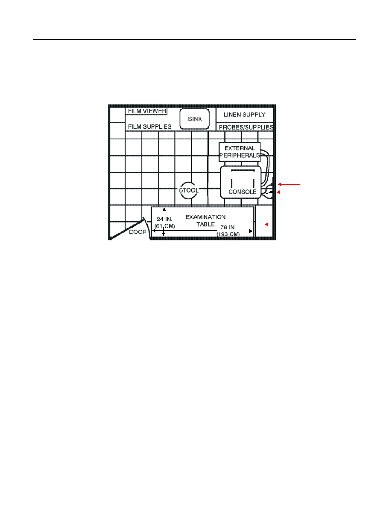
PRELIMINARY
VIVID 3
36 IN.
(92 CM)
Dedicated Power Outlets
Hospital Network
GE Cabinet for
Software and Manuals
(optional)
GE
P
ART NUMBER FN091065, REVISION 2 VS5 N AND VS6 N SERVICE MANUAL
2-3-3-1 Recommended Ultrasound Room Layout
Figure 2-1 below shows a floor plan illustrating the recommended layout of the Ultrasound Room and
depicting the minimal room layout requirements.
Figure 2-1 Recommended Floor Plan 4.3m x 5.2m (14 ft x 17 ft)
Chapter 2 - Site Preparations 2-9
Page 72

PRELIMINARY
GE
P
ART NUMBER FN091065, REVISION 2 VS5 N AND VS6 N SERVICE MANUAL
2-3-4 Networking Pre-Installation Requirements
2-3-4-1 Stand-alone Unit (without Network Connection)
None.
2-3-4-2 Unit Connected to Hospital’s Network
Supported networks:
• Wireless LAN
2-3-4-3 Purpose of the DICOM Network Function
DICOM services provide the operator with clinically useful features for moving images and patient
information over a hospital network. Examples of DICOM services include the transfer of images to
workstations for viewing or transferring images to remote printers. As an added benefit, transferring
images in this manner frees up the on-board moni tor and peripherals, enabling viewing to be done while
scanning continues. With DICOM, images can be archived, stored, and retrieved faster, easier, a nd at
a lower cost.
2-3-4-4 DICOM Option Pre-Installation Requirements
To configure the Vivid S5 N or Vivid S6 N ultrasound unit to work with other network connections, the
network administrator must provide the required information, which should include the following:
• Details: DICOM network details for the Vivid S5 N or Vivid S6 N unit,
including the host name, local port, IP address, AE title and net
mask.
• Routing Information: IP addresses for the default gateway and other routers in use at
the site.
• DICOM Application Information:Details of the DICOM devices in use at the site, including the
DICOM host name, AE title and IP addresses.
2-10 Section 2-3 - Facility Needs
Page 73
PRELIMINARY
Site System Information
Services (Destination Devices)
TCP/IP Settings
Device Type
Manufacturer
Name
IP Address
Port
AE Title
1
2
3
4
5
6
7
8
9
10
11
12
Dept:
Vivid S5 N or
Vivid S6 N SN:
Type:
Floor:
Room:
REV:
Comments:
CONTACT INFORMATION
Name
Title
Phone
E-Mail Address
Site:
Scanner IP Settings
IP Address:
Subnet Mask:
Default Gateway:
(Echo Server/GEMNet Server/EchoPac PC)
Server Name:
Remote DB User Name:
Name - AE Title:
Remote Archive Setup
IP Address:
Subnet Mask:
Default Gateway:
Name - AE Title:
GE
P
ART NUMBER FN091065, REVISION 2 VS5 N AND VS6 N SERVICE MANUAL
Section 2-4 Connectivity Installation Worksheet
Figure 2-2 Connectivity Installation Worksheet
Chapter 2 - Site Preparations 2-11
Page 74
PRELIMINARY
Vivid S5 N or Vivid S6 N
Host Name
AE Title
Local Port
IP Address
Net Mask
...
...
ROUTING INFORMATION
ROUTER2
ROUTER3
ROUTER1
...
...
...
...
...
...
...
Destination
IP Addresses
GATEWAY IP Addresses
Default
DICOM APPLICATION INFORMATION
NAME
Store 2
Store 3
Store 1
MAKE/REVISION IP ADDRESSES PORTAE TITLE
Store 5
Store 6
Store 4
Storage
Commit
MPPS
Work list
...
...
...
...
...
...
...
...
...
GE
P
ART NUMBER FN091065, REVISION 2 VS5 N AND VS6 N SERVICE MANUAL
Section 2-4 Connectivity Installation Worksheet (cont’d)
Figure 2-3 Worksheet for DICOM Network Information
2-12 Section 2-4 - Connectivity Installation Worksheet
Page 75
PRELIMINARY
GE
P
ART NUMBER FN091065, REVISION 2 VS5 N AND VS6 N SERVICE MANUAL
Section 2-4 Connectivity Installation Worksheet (cont’d)
Table 2-7 Vivid™ S5 N and Vivid™ S6 N Pre-Installation Check List
Action Yes No
Schedule at least 3 hours for installation of the system.
Notify installation team of the existence of any variances from the basic installation.
Make sure system and probes have been subject to acclimation period.
Environmental cooling is sufficient.
Lighting is adjustable to adapt to varying operational conditions of the scanner.
Electrical facilities meet system requirements.
EMI precautions have been taken and all possible sources of interference have been
removed.
Mandatory site requirements have been met.
If a network is used, IP address has been set for the system and a dedicated network
outlet is available.
Chapter 2 - Site Preparations 2-13
Page 76

PRELIMINARY
GE
P
ART NUMBER FN091065, REVISION 2 VS5 N AND VS6 N SERVICE MANUAL
This page was intentionally left blank.
2-14 Section 2-4 - Connectivity Installation Worksheet
Page 77

PRELIMINARY
GE
P
ART NUMBER FN091065, REVISION 2 VS5 N AND VS6 N SERVICE MANUAL
Chapter 3
System Setup
Section 3-1 Overview
3-1-1 Purpose of Chapter 3
This chapter provides instructions for installing the Vivid S5 N and Vivid S6 N Ultrasound system. Before
beginning the installation process, an appropriate site must be prepared, as described in Chapter 2.
Once the site has been prepared, installation can proceed as described in this chapter.
Included in this chapter are guidelines for transporting the unit to a new site, as well as procedures tha t
describe how to receive and unpack the equipment, and (if necessary) how to file a damage or loss
claim. Instructions for checking and testing the unit, probes, and external peripherals for electrical safety
are also provided.
NOTE: As described in ‘Installation Acceptance Test Criteria” on page 3-192, a Vivid S5 N / Vivid S6 N
ultrasound scanner is ready for use after the system has been configured successfully in
accordance with the information provided in Chapter 3 (this chapter).
NOTE: Depending on the customer’s specific requirements, the Vivid S5 N or Vivid S6 N portable
ultrasound scanner will have been supplied. Where applicable, the installation procedures for
each scenario are clearly identified in this chapter.
Table 3-1 Contents in Chapter 3
Section Description Page Number
3-1
3-2
3-3
3-4
3-5
3-6
3-7
3-8
3-9
Overview
Installation Reminders
Receiving and Unpacking the Equipment
Preparing for Installation
Completing the Hardware Installation
Configuration
Connectivity Setup
Storing and Transporting the Unit
Completing the Installation Paperwork
3-1
3-2
3-4
3-14
3-26
3-80
3-96
3-186
3-192
Chapter 3 - System Setup 3-1
Page 78
PRELIMINARY
CAUTION
GE
P
ART NUMBER FN091065, REVISION 2 VS5 N AND VS6 N SERVICE MANUAL
Section 3-2 Installation Reminders
3-2-1 Average Installation Time
The Vivid S5 N or Vivid S6 N installation and functional checkout will take approximately one hour; Vivid
S5 N or Vivid S6 N consoles with optional equipment may take slightly longer.
Once the site has been prepared, the average installation time required is shown in Table 3-2 below.
Table 3-2 Average Installation Time
Average
Description
Unpacking the scanner 30 minutes
Installing the scanner 30 minutes Time may vary, according to the required configuration
DICOM Option
(connectivity)
Installation Time
30 minutes Time may vary, according to the required configuration
Comments
3-2-2 Installation Warnings
1.) The Vivid S5 N or Vivid S6 N ultrasound scanner weighs 65 Kgs (143 lbs), without
add-ons/peripherals.
Two people are always required to unpack the system.
2.) There are no operator-serviceable components. To prevent shock, do not remove any covers or
panels. If problems or malfunctions occur, unplug the power cord. Only qualified service personnel
should carry out servicing and troubleshooting.
NOTE: For information on shipping carton labels, refer to Figure 3-1 on page 3-5 and Fig ur e 3- 4 on
page 3-7.
3-2-2-1 System Acclimation Time
Following transport, the Vivid S5 N or Vivid S6 N system may be very cold, or hot. Allow time for the
system to acclimate before being switched ON. Acclimation requires 1 hour for each 2.5
when the temperature of the system is below 10
Turning the system ON after arrival at the site - without allowing time for acclimation - may
cause system damage!
Table 3-3 Vivid™ S5 N and Vivid™ S6 N System Acclimation Time
60 55 50 45 40 35 30 25 20 15 10 5 0 -5 -10 -15 -20 -25 -30 -35 -40
°C
140 131 122 113 104 96 86 77 68 59 50 41 32 23 14 5 -4 -13 -22 -31 -40
°F
o
C or above 35oC.
o
C increment,
864200000002468101214161820
Hrs
NOTE: After a long period of storage, or after transportation of the system with the monitor in the folded-down
position, it is highly recommended to place the monitor in the upright position - and to leave it in this
position for a period of longer than 1 hour before use. This will enable it to properly adjust to the
environmental conditions.
3-2 -
Page 79
PRELIMINARY
DANGER
WARNINGWARNING
CAUTION
CAUTION
CAUTION
CAUTION
WARNINGWARNING
GE
P
ART NUMBER FN091065, REVISION 2 VS5 N AND VS6 N SERVICE MANUAL
3-2-3 Safety Reminders
WHEN USING ANY TEST INSTRUMENT THAT IS CAPABLE OF OPENING THE
AC GROUND LINE (I.E., METER’S GROUND SWITCH IS OPEN), DO NOT TOUCH
THE UNIT!
TWO PEOPLE ARE REQUIRED TO UNPACK THE SYSTEM AS IT IS HEAVY.
TWO PEOPLE ARE ALWAYS REQUIRED WHENEVER A PART WEIGHING 19KG (35 LB.)
OR MORE MUST BE LIFTED.
IF THE UNIT IS VERY COLD OR HOT, DO NOT TURN ON POWER TO THE UNIT UNTIL IT HAS
HAD SUFFICIENT TIME TO ACCLIMATE TO ITS OPERATING ENVIRONMENT.
TO PREVENT ELECTRICAL SHOCK, CONNECT THE UNIT TO A PROPERLY GROUNDED
POWER OUTLET.
DO NOT USE A THREE-PRONG TO TWO-PRONG ADAPTER, AS THIS DEFEATS SAFETY
GROUNDING.
DO NOT WEAR THE ESD WRIST STRAP WHEN YOU WORK ON LIVE CIRCUITS WHERE MORE
THAN 30 V PEAK IS PRESENT.
DO NOT OPERATE THE UNIT UNLESS ALL BOARD COVERS AND FRAME PANELS ARE
SECURELY IN PLACE, TO ENSURE OPTIMAL SYSTEM PERFORMANCE AND COOLING.
(WHEN COVERS ARE REMOVED, EMI MAY BE PRESENT).
ACOUSTIC OUTPUT HAZARD
ALTHOUGH THE ULTRASOUND ENERGY TRANSMITTED FROM THE
Vivid S5 N or Vivid S6 N PORTABLE ULTRASOUND SCANNER IS WITHIN AIUM/NEMA
STANDARDS AND FDA LIMITATIONS, AVOID UNNECESSARY EXPOSURE.
ULTRASOUND ENERGY CAN PRODUCE HEAT AND MECHANICAL DAMAGE
Note: The Vivid S5 N or Vivid S6 N User Manual should be fully read and understood before oper ating
the unit. Keep the manual near the unit for reference.
.
Chapter 3 - System Setup 3-3
Page 80

PRELIMINARY
CAUTION
NOTICE
GE
P
ART NUMBER FN091065, REVISION 2 VS5 N AND VS6 N SERVICE MANUAL
Section 3-3 Receiving and Unpacking the Equipment
Please read this section fully before unpacking the Vivid S5 N or Vivid S6 N ultrasound unit.
The Vivid S5 N or Vivid S6 N ultrasound unit, together with the peripherals, probes, cables, and
accessories, are shipped from the factory in a single cardboard shipping carton mounted on a raised
wooden base - see Figure 3-2 on page 3-6.
Where the specific customer requirements are for a Vivid S5 N or Vivid S6 N ultrasound unit with
peripherals, this is shipped in a smaller-sized cardboard shipping ca rton moun ted on a ra ised wo oden
base, or placed on top of the main cardboard carton that contains the scanner- see Figure 3-3 on
page 3-7.
Unpacking instructions for each type of shipping carton are provided separately in the following
sections:
• ‘Unpacking the Vivid S5 N or Vivid S6 N with Peripherals” on page 3-8
• ‘Unpacking the Vivid S5 N or Vivid S6 N” on page 3-9
NOTE: For details of weights and dimensions of all three shipping cartons, refer to Table 3-4 on page 3-7.
Each cardboard shipping carton is sealed with plastic tape and secured on the outside with plastic
straps. The interior of the carton is fully lined with re-sealable water-proof wrapping to protect the
contents from external moisture; silica gel bags are also placed among the contents to absorb any
condensation or moisture within the carton.
Before unpacking the unit
• Inspect the carton for visible damage.
• Inspect the Drop and Tilt indicators (on the Shock-watch and Tilt-watch labels, respectively) for
evidence of accidental shock or tilting during transit (damage incident) - refer to Figure 3-1
below.
After unpacking the unit:
It is recommended to keep and store the shipping carton and all other packing materials
(including the support foams, anti-static plastic cover, et c.), in c ase the unit ha s to be mov ed to
a different location in the future.
For warranty purposes, storage of the above is required for one year from date of purchase.
3-4 -
Page 81
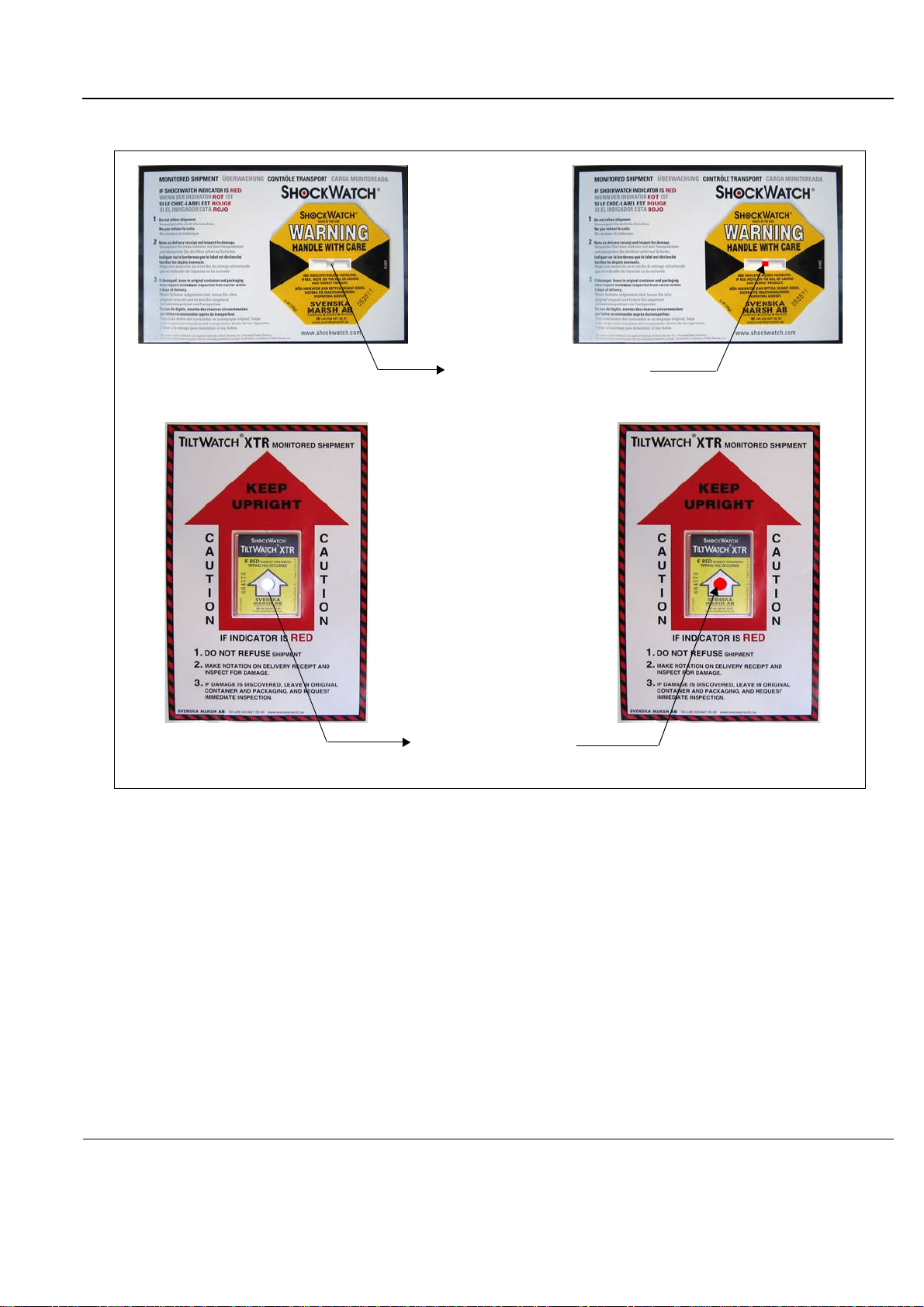
PRELIMINARY
Tilt indicators turn Red
Shock indicators turn Red
GE
P
ART NUMBER FN091065, REVISION 2 VS5 N AND VS6 N SERVICE MANUAL
Figure 3-1 Drop and Tilt Indicators
If the carton is damaged, or if either the Drop or Tilt indicators have turned red (indicating damage
incident), please inform the GE HEALTHCARE sales representative immediately. In addition, mark on
the shipping consignment note or packing slip/post-delivery checklist (in the “Package” column) that the
Tilt and/or Drop indicators show damage incident.
Chapter 3 - System Setup 3-5
Page 82
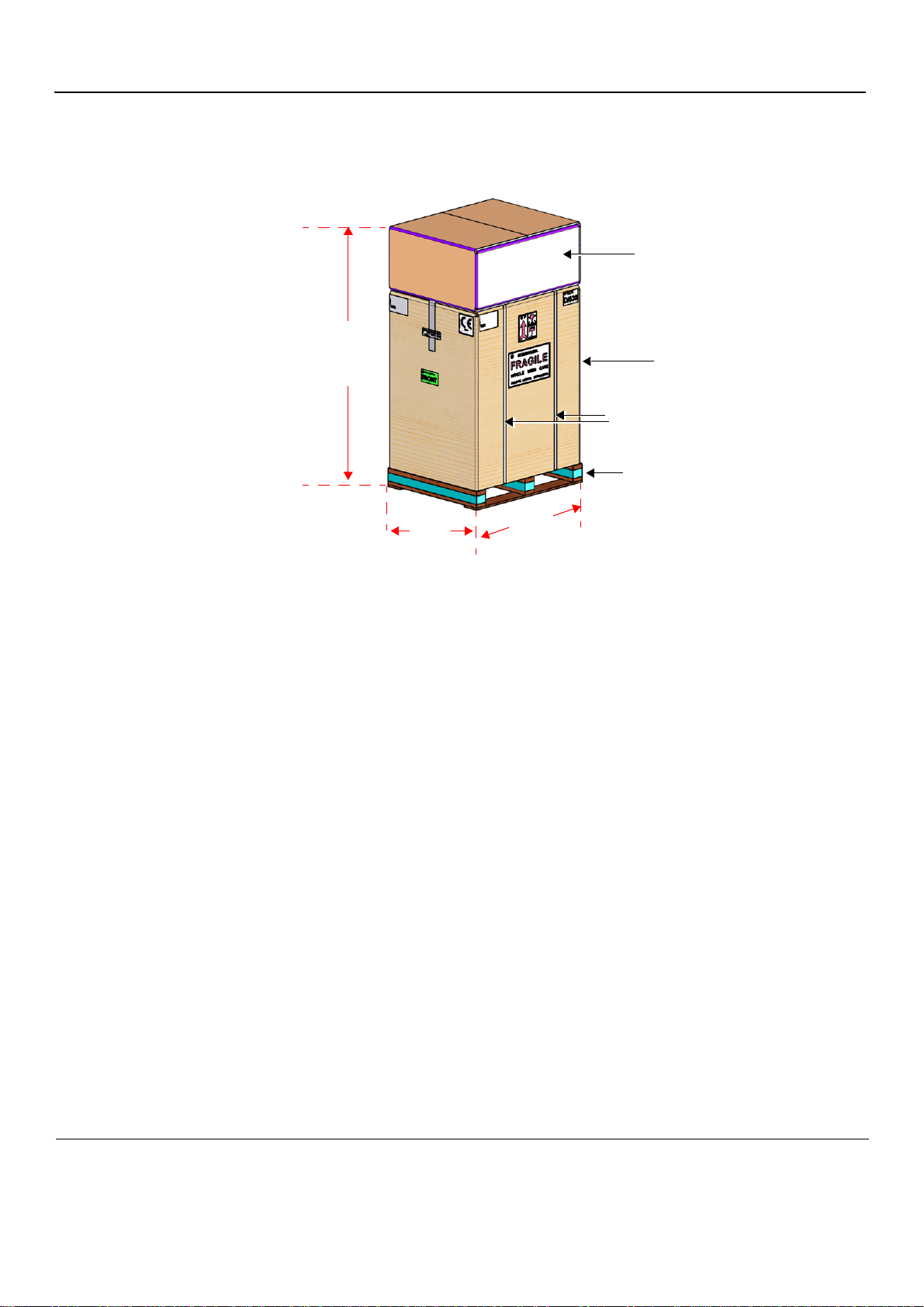
PRELIMINARY
Peripherals
Height
157 cm (62 in)
Width
73 cm (29 in)
FRONT
Depth
87 cm (34 in)
Ultrasound Scanner
Wooden Base
Plastic Straps
Note: Weight = 105 Kgs (231 lbs)
GE
P
ART NUMBER FN091065, REVISION 2 VS5 N AND VS6 N SERVICE MANUAL
Figure 3-2 Shipping Carton - Vivid S5 N and Vivid S6 N with Peripherals
3-6 -
Page 83
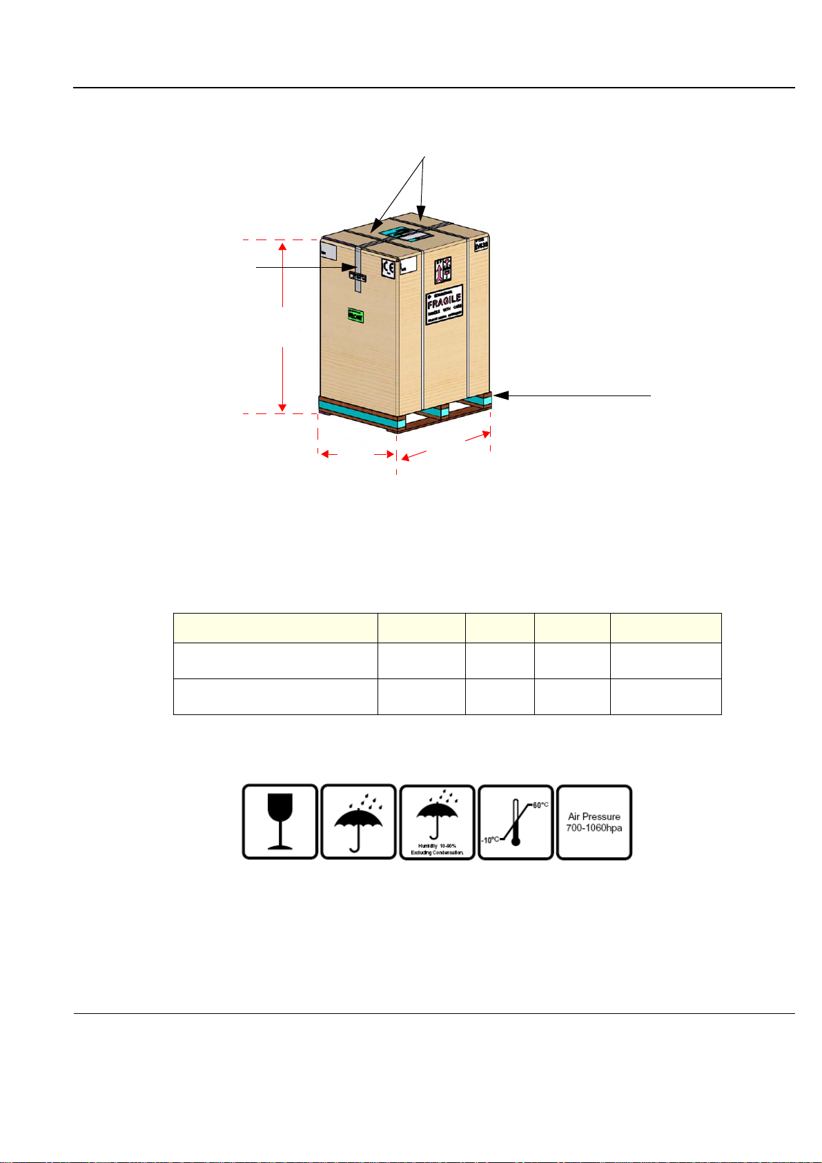
PRELIMINARY
Height
119 cm (47 in)
Width
73 cm (29 in)
FRONT
Depth
87 cm (34 in)
Note: Weight = 95 Kgs (209 lbs)
Plastic Straps
Adhesive Tape
Wooden Base
GE
P
ART NUMBER FN091065, REVISION 2 VS5 N AND VS6 N SERVICE MANUAL
Figure 3-3 Shipping Carton - Vivid S5 N and Vivid S6 N Only
Table 3-4 Shipping Cartons - Dimensions and Weights
Description Height Width Depth
Vivid S5 N or Vivid S6 N scanner
with peripherals and accessories
Vivid S5 N or Vivid S6 N scanner only
a. Weight is approximate and will vary depending upon the supplied peripherals
157 cm
62 ins
119 cm
47 ins
73 cm
29 ins
73 cm
29 ins
Figure 3-4 Additional Labels on Shipping Carton
87 cm
34 ins
87cm
34 ins
Weight
105 kgs
231 lbs
95 kgs
209 lbs
a
Chapter 3 - System Setup 3-7
Page 84

PRELIMINARY
CAUTION
GE
P
ART NUMBER FN091065, REVISION 2 VS5 N AND VS6 N SERVICE MANUAL
3-3-1 Unpacking the Cardboard Shipping Carton
As previously described, the Vivid S5 N or Vivid S6 N ultrasound unit is packed in a single cardboard
shipping carton comprising a durable outer cardboard carton cover and a wooden platform base ; these
are firmly joined together with plastic straps. After completing a visual inspection of the shipping carton
and Drop/Tilt indicators, proceed to the unpacking instructions below, as appropriate
3-3-1-1 Unpacking the Vivid S5 N or Vivid S6 N with Peripherals
1.) Cut the plastic straps securing the shipping carton to the wooden base - see Figure 3-2 on page 3-6.
WHEN USING SHARP TOOLS TO OPEN PACKING MATERIALS, TAKE CARE TO AVOID
CUTTING OR DAMAGING ANY OF THE CONTENTS.
2.) Remove the options peripherals box (smaller-sized cardboa rd shipp i ng ca rton ) fr om the top of the
main cardboard shipping carton that contains the scanner.
3.) Carefully cut the adhesive tape used to close the shipping carton lids, and open the cartons from the top.
4.) Undo the re-sealable water-pr oof carton liners.
5.) Remove the packing slip (shipping consignment note) detailing the contents of the ship ping carton
and keep close to hand ready to mark the check list.
6.) Continue with unpacking the main cardboard shipping carton that contains the scanner, as
indicated in ‘Unpacking the Vivid S5 N or Vivid S6 N” on page 3-9.
3-8 -
Page 85
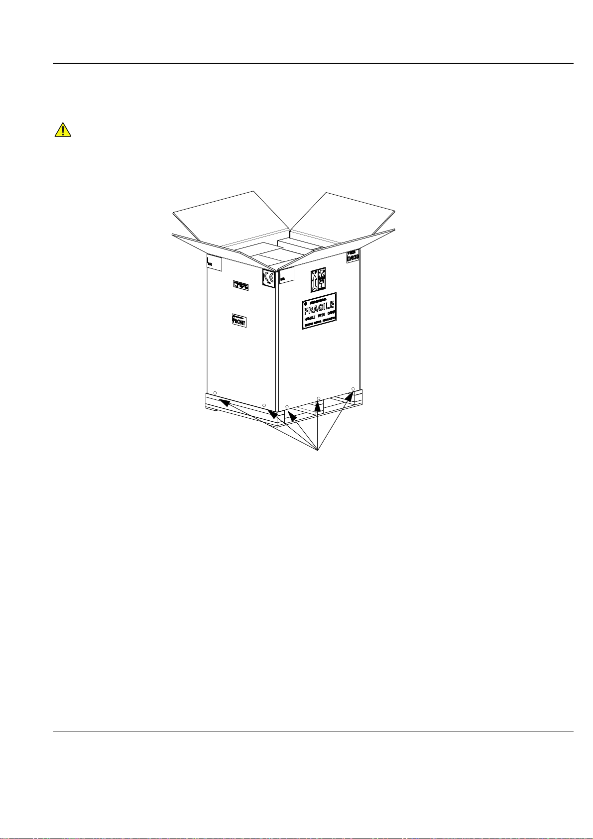
PRELIMINARY
CAUTION
Remove Screws
GE
P
ART NUMBER FN091065, REVISION 2 VS5 N AND VS6 N SERVICE MANUAL
3-3-1-2 Unpacking the Vivid S5 N or Vivid S6 N
1.) Cut the two plastic straps securing the shipping carton to the wooden base - see Figure 3-3 on
page 3-7.
WHEN USING SHARP TOOLS TO OPEN PACKING MATERIALS, TAKE CARE TO AVOID
CUTTING OR DAMAGING ANY OF THE CONTENTS.
2.) Carefully cut the adhesive tape used to close the shipping carton upper lid and open the four folded
flaps - see Figure 3-5.
Figure 3-5 Opening the Shipping Carton
3.) From each side, remove the screws securing the outer cardboard to the wooden base.
4.) Remove the outer cardboard walls pulling them gently upwards and away from the system
(Figure 3-6).
Chapter 3 - System Setup 3-9
Page 86
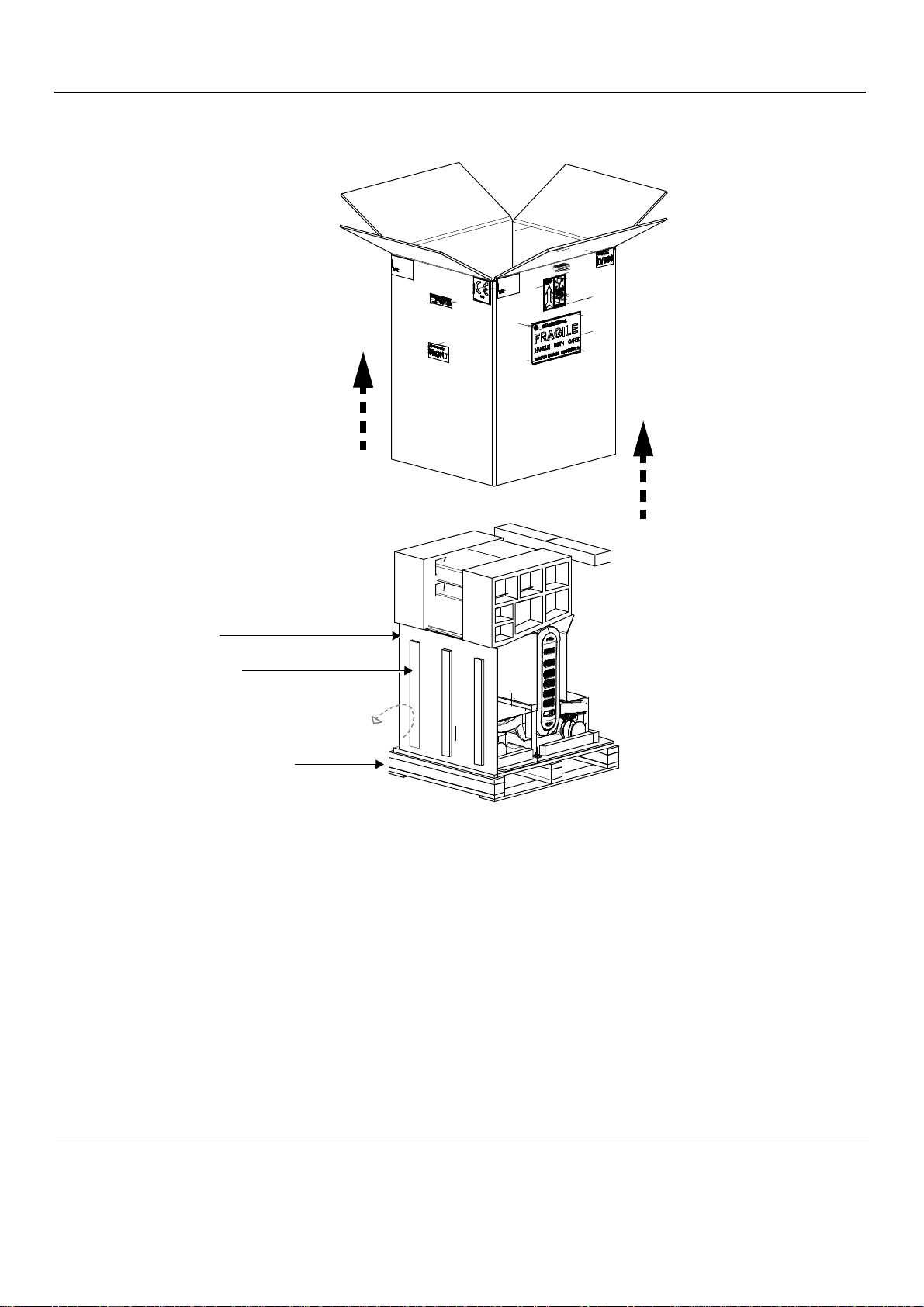
PRELIMINARY
Wooden Base
Guide Rail
Wheeling Ramp
(in upright position)
GE
P
ART NUMBER FN091065, REVISION 2 VS5 N AND VS6 N SERVICE MANUAL
Figure 3-6 Wheeling Ramp in Upright Position
Note: The front side of the carton is reinforced with wooden guide rails and, when dropped down
in the open position, these form a strong ramp used for wheeling the system out of the
shipping carton.
5.) Remove the packing slip (shipping consignment note) detailing the contents of the ship ping carton
and keep close to hand ready to mark the check list.
3-10 -
Page 87
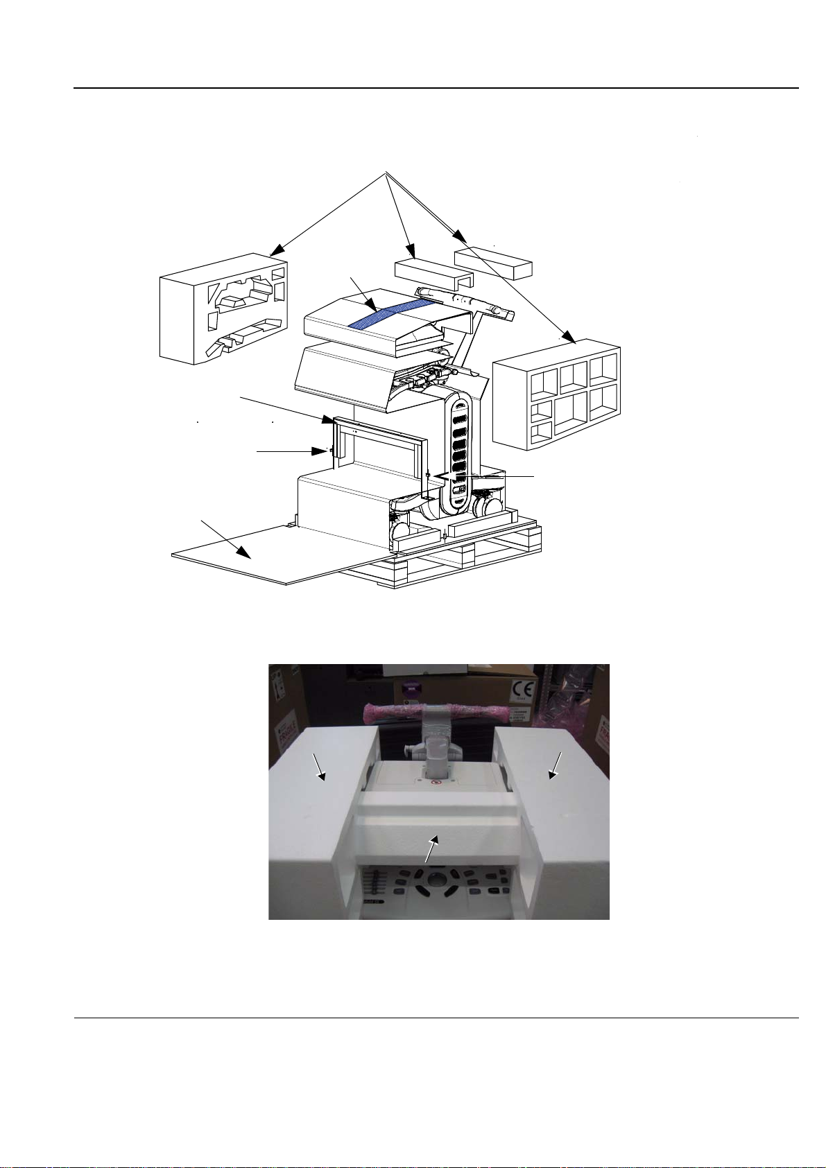
PRELIMINARY
Foam Supports
Console Holder
Unscrew to remove
Console Holder
Unscrew to remove
Console Holder
Wheeling Ramp
Adhesive tape
GE
P
ART NUMBER FN091065, REVISION 2 VS5 N AND VS6 N SERVICE MANUAL
6.) Lower the wheeling ramp into the unloading position, as shown in Figure 3-7 on page 3-11.
Figure 3-7 Wheeling Ramp in Unloading Position for Scanner Removal
7.) Carefully remove the three foam supports (from the side and top of the monitor) - see Figure 3-8.
Figure 3-8 Foam Supports Protecting the LCD Screen
Chapter 3 - System Setup 3-11
Page 88
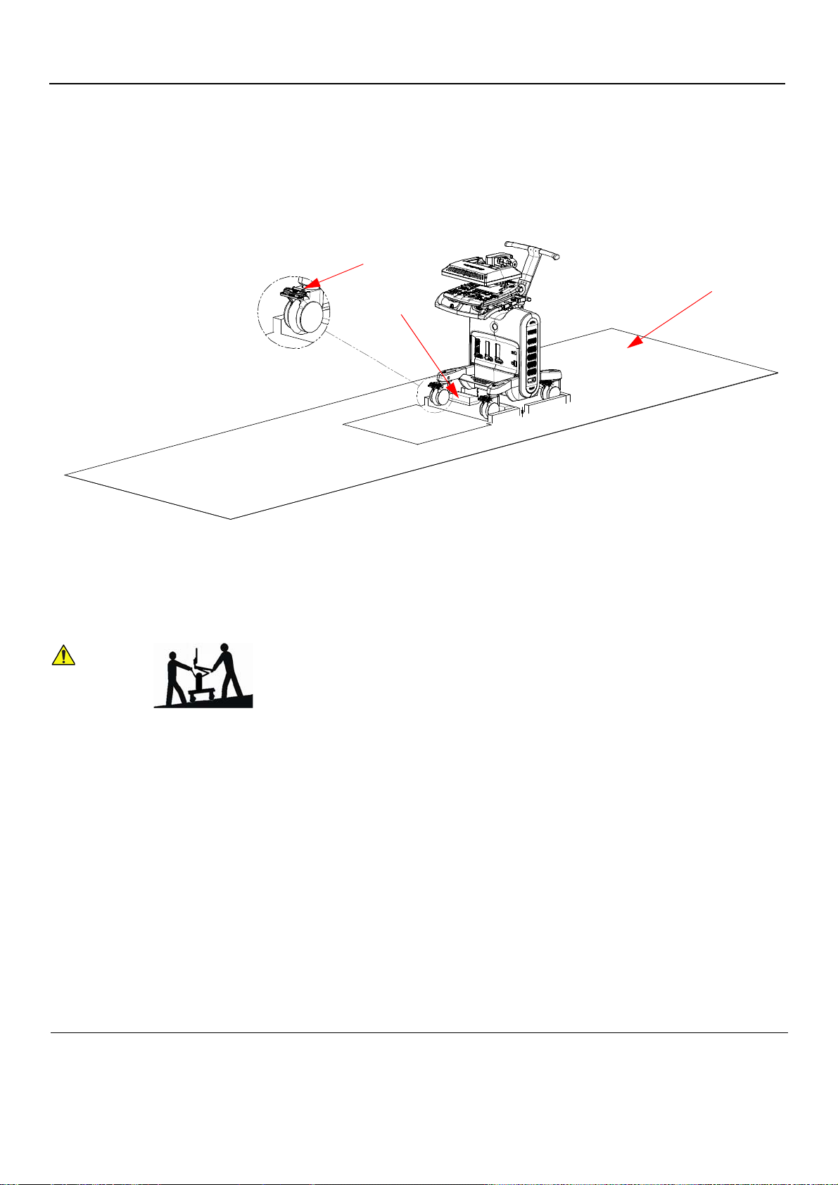
PRELIMINARY
CAUTION
Silica gel bags
Locking brake
Anti-static nylon on floor
GE
P
ART NUMBER FN091065, REVISION 2 VS5 N AND VS6 N SERVICE MANUAL
8.) Remove the two screws that secure the console holder, then remove the holder (Figure 3-7).
9.) Carefully remove the adhesive tape from the top of the syste m and spread the anti-static nylo n o n
the floor.
10.)Remove any additional packing material from in front of and surrounding the system.
11.)Remove the two silica gel bags (Figure 3-9).
Figure 3-9 Locking Wheel Brake
12.)Press down on the locking brake to unlock the wheel. Repeat for the three other wheels.
13.)Using two people, carefully roll the scanner forwards down the unloading ramp to remove it
completely from the shipping carton.
TWO PEOPLE ARE REQUIRED WHEN MOVING THE Vivid S5 N or Vivid S6 N
SCANNER.
This precaution is intended to prevent injury that may be caused by the weight of the
system if one person attempts to move the scanner considerable distances or on an
incline.
14.)Make sure the system is standing firmly on the floor before applying the locking brake.
15.)Remove the foam sections from the top of the system and from between the main shelf and
probe shelf.
16.)Using the up/down handle, raise the main shelf up to appropriate height.
17.)Pull the monitor locking pin towards you and lift the monitor into the upright position.
18.)Before commencing the installation procedure, follow the instructions for ‘Verifying the Shipping
Carton Contents” on page 3-13.
3-12 -
Page 89

PRELIMINARY
NOTICE
WARNINGWARNING
GE
P
ART NUMBER FN091065, REVISION 2 VS5 N AND VS6 N SERVICE MANUAL
3-3-2 Verifying the Shipping Carton Contents
After unpacking, it is important to verify that all items ordered by the customer have been received.
Compare all items listed on the packing slip (shipping consign ment note) with those received and report
any items that are missing, back-ordered, or dam aged, to your GE HEALTHCARE sales representative.
The contact address is shown in ‘Contact Information” on page 1-27.
IT IS RECOMMENDED TO KEEP AND STORE THE SHIPPING CARTON AND ALL OTHER
PACKING MATERIALS (INCLUDING THE SUPPORT FOAMS, ANTI-STATIC PLASTIC COVER,
ETC.), IN CASE THE UNIT HAS TO BE MOVED TO A DIFFERENT LOCATION IN THE FUTURE.
FOR WARRANTY PURPOSES, STORAGE OF THE ABOVE IS REQUIRED FOR ONE YEAR FROM
DATE OF PURCHASE.
3-3-3 Physical Inspection
3-3-3-1 System Voltage Settings
Verify that the Vivid S5 N or Vivid S6 N ultrasound AC is set to the correct voltage.
The Voltage settings are:
• 220-240V AC - Europe, all Asia excluding Japan and Taiwan.
• 100-120V AC - Americas, Japan and Taiwan.
NOTE: Applicable to Vivid S5 N / Vivid S6 N systems with AC Distribution Box Type B or Type A.
SETTING THE Vivid S5 N or Vivid S6 N ULTRASOUND COMPONENTS TO THE WRONG
VOLTAGE SETTING WILL MOST LIKELY DESTROY THE EQUIPMENT.
3-3-4 EMI Protection
The Vivid S5 N or Vivid S6 N Ultrasound Unit has been designed to minimize the effects of Electro
Magnetic Interference (EMI). Many of the covers, shields, and screws are provided primarily to protect
the system from image artifacts caused by this interference. For this reason, it is imperative that all
covers and hardware are installed and secured before the unit is put into operation.
Chapter 3 - System Setup 3-13
Page 90
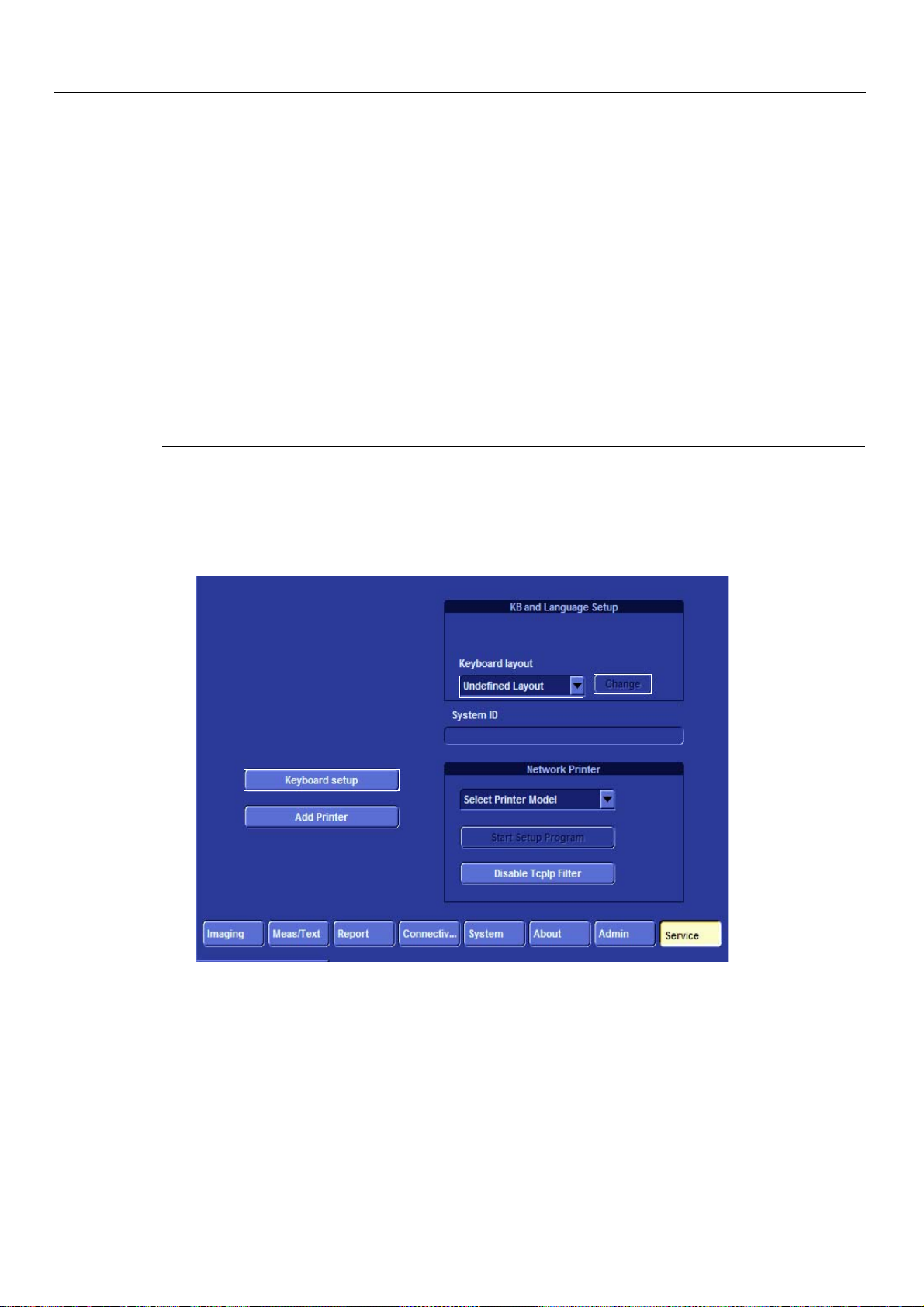
PRELIMINARY
GE
P
ART NUMBER FN091065, REVISION 2 VS5 N AND VS6 N SERVICE MANUAL
Section 3-4 Preparing for Installation
3-4-1 Confirming Customer Order
When preparing for installation of a Vivid S5 N or Vivid S6 N system, after unpacking the equipment, it
is important to verify that all items ordered by the customer have been received. Comp are all items listed
on the packing slip (delivery note/shipping consignment note) with tho se received and report any items
that are missing, back-ordered, or damaged, to your GE sales representative.
3-4-1-1 Probes
The shipping carton will contain the probes that have been ordered with the system.
For a list of probes available for use with the Vivid S5 N or Vivid S6 N portab le ultrasound scanner, refer
to Section 9-9 "Probes" on page 9-16.
3-4-2 Language Change
Language Selection
1.) Switch on the Vivid S5 N or Vivid S6 N system.
2.) Once the system has booted up, press Config and log on to the system.
3.) Click the Service button to open the Service screen - see Figure 3-10.
Figure 3-10 Service Screen
4.) From the Keyboard Layout dropdown list, select the required language and click Change.
NOTE: Always select the general name of the language and not sub-dialects. For example, s elect
“German” (Germany) and not German (Austria).
3-14 Section 3-4 - Preparing for Installation
Page 91
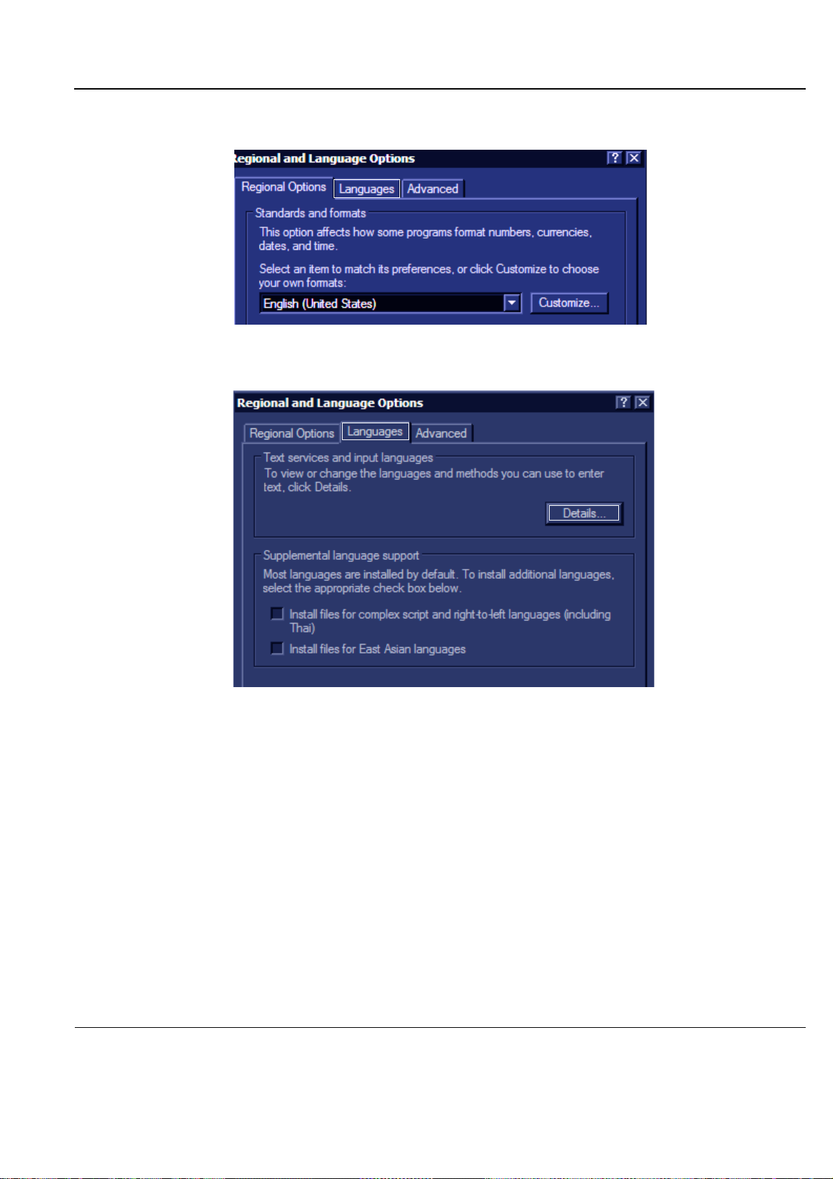
PRELIMINARY
GE
P
ART NUMBER FN091065, REVISION 2 VS5 N AND VS6 N SERVICE MANUAL
5.) From the Service screen, click Keyboard Setup. The Regional Language Option window op ens see Figure 3-11.
Figure 3-11 Regional Language Options window
6.) Select the Languages tab and in the next window click the Details... button - see Figure 3-12.
Figure 3-12 Regional Language Options
Chapter 3 - System Setup 3-15
Page 92
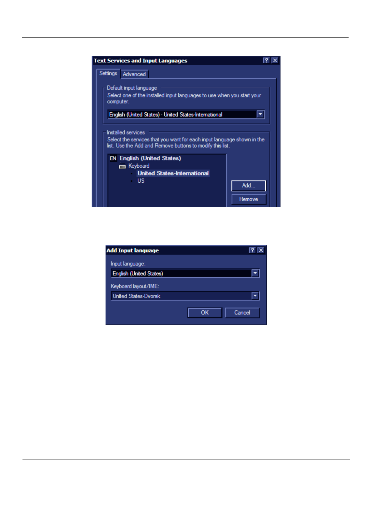
PRELIMINARY
GE
P
ART NUMBER FN091065, REVISION 2 VS5 N AND VS6 N SERVICE MANUAL
7.) The Text Services and Input Languages window opens - see Figure 3-13.
Figure 3-13 Text Services and Input Languages window
8.) From the Text Services and Input Languages screen, click Add. T he Add Inpu t Langu age dia log
box opens - see Figure 3-14.
Figure 3-14 Add Input Language dialog box
9.) From the Input Language dropdown list, select the language to be installed and click OK. The Text
Services and Input Languages screen opens.
10.)From the Default Input Language box, select the language to be installed and click Apply.
11.)Click OK and in the following screens click OK again to return to the Service window.
12.)From the console, press Escape and restart the system.
13.)Proceed to verify the language change - see ‘Verifying the Language Change” on page 3-17.
3-16 Section 3-4 - Preparing for Installation
Page 93

PRELIMINARY
GE
P
ART NUMBER FN091065, REVISION 2 VS5 N AND VS6 N SERVICE MANUAL
Verifying the Language Change
Once the language is installed, it is necessary to verify that the language change was correctly
implemented. This test requires the selection of various special language keys used in the
newly-installed language and to verify their correct display on the screen.
1.) Log on in Maintenance mode.
2.) From the Desktop screen, open Microsoft Notepad.
3.) Press the Alt Gr key and at the same time press a sp ecial language key and verify that the selected
letter/symbol is displayed on the screen.
4.) Repeat the previous step using other special language keys to confirm that the language change
has been correctly implemented.
Chapter 3 - System Setup 3-17
Page 94

PRELIMINARY
GE
P
ART NUMBER FN091065, REVISION 2 VS5 N AND VS6 N SERVICE MANUAL
3-4-3 Component Inspection
After verifying that all the required parts are included in the shipping crate, inspect the system
components using the checklist supplied below. In addition, ensure that all the labels described in
Chapter 1 - are present, accurate and in good condition, and enter the serial number printed on the
main label into the system installation details card, as described in System Installation Details on page
3-192.
3-4-3-1 Damage Inspection Checklist
Visually inspect the contents of the shipping carton for damage. If any parts are damaged or missing,
contact an authorized GE Service Representative.
A Damage Inspection Checklist for th e Vivid S5 N or Vivid S6 N portable ultrasound scanner is provided
in Table 3-5 below.
Table 3-5 Damage Inspection Checklist - Vivid S5 N and Vivid S6 N Syste m s
Step Item Recommended Procedure
1
Console
2
Control Console
3
Probes
4
LCD Display
5
Fans
6
Rear Panel
7
Covers
8
Peripherals
10
Probe Holders Clean the gel wells with warm water and a damp cloth to remove all traces of gel.
13
Covers Check that all screws are in place, all chassis and internal covers are installed.
Verify that the system is switched OFF and unplugged. Clean the console and
control panel.
Physically inspect the control console for missing or damaged items. Verify the
proper illumination of all the control panel buttons.
Check all probes for wear and tear on the lens, cable, and connector. Look for bent
or damaged pins on the connector and in the connector socket on the unit. Verify
that the EMI fingers around the probe connector socket housing are intact. Check
the probe locking mechanism and probe switch.
Clean the LCD display by gently wiping with a dry, soft, lint-free non-abrasive
folded cloth. Inspect the monitor for scratches and raster burn.
Turn on the system and verify that the system’s cooling fans and peripheral fans
are operating.
Check the rear panel connectors for bent pins, loose connections and loose or
missing hardware. Screw all the cable connectors tightly to the connector sockets
on the panel. Verify that the labeling is in good condition.
Check that all screws are tightly secured in place, that there are no dents or
scratches and that no internal parts are exposed.
Check and clean the peripherals in accordance with the manufacturer’s directions.
To prevent EMI or system overheating, dress the peripheral cables inside the
peripheral cover.
14
15
Peripherals
AC System
Check and clean the peripherals in accordance with the manufacturer’s directions.
To prevent EMI or system overheating, dress the peripheral cables inside the
peripheral cover.
Check the AC board connectors and the associated cabling for good connection
and proper insulation. Verify that the connections are secured.
3-18 Section 3-4 - Preparing for Installation
Page 95
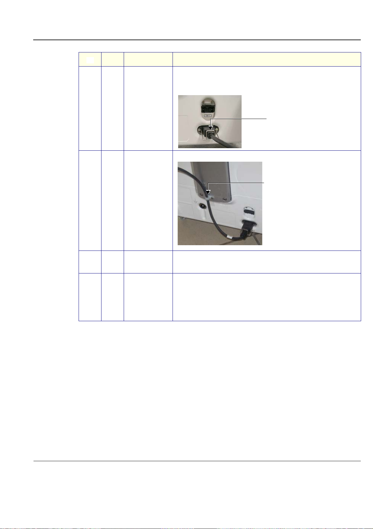
PRELIMINARY
Clamp securing power cord
AC cable secured with plastic clamp
GE
P
ART NUMBER FN091065, REVISION 2 VS5 N AND VS6 N SERVICE MANUAL
Table 3-5 Damage Inspection Checklist - Vivid S5 N and Vivid S6 N Systems (cont’d)
Step Item Recommended Procedure
Check the power cord for cuts, loose hardware, tire marks, exposed insulation, or
any deterioration. Verify continuity.
Tighten the clamps that secure the power cord to the unit and the outlet plug to the
cord. Replace the power cord and/or clamp, as required.
16
Power Cord
Secure the cable to the back of the system using the plastic clamp provided.
17
18
19
Front Castors
Rear Castors
Check that the front castors can roll and swivel, and can be placed in the locked
position by pressing the foot brake (lower lever) down on each.
Ensure that the wheels are locked and there is no movement in any direction.
For Vivid S6 N systems:
Check that the rear castors can roll and swivel, and can be placed in the locked
position by pressing the foot brake (lower lever) down on each.
Ensure that the wheels are locked, unable to swivel left or right, and that there is
no movement forwards or backwards.
For Vivid S5 N systems:
Check that the rear castors can roll and swivel freely.
Chapter 3 - System Setup 3-19
Page 96
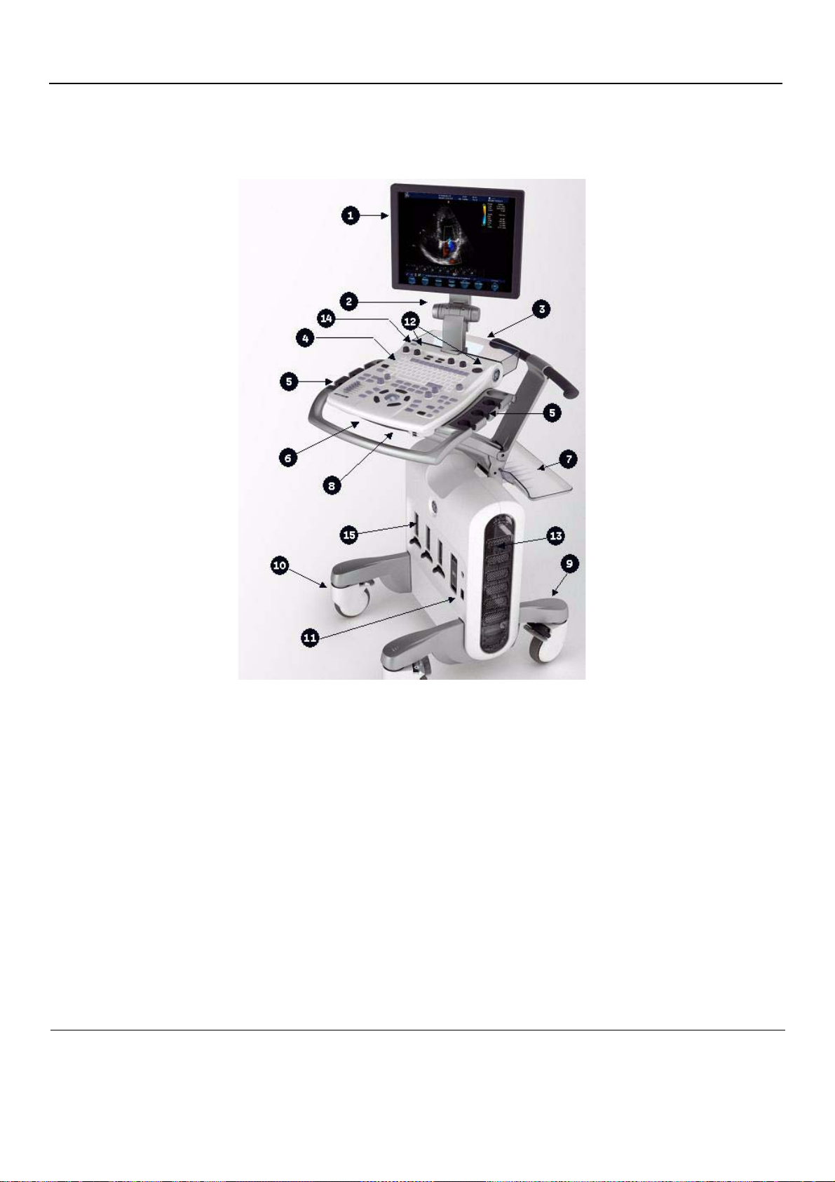
PRELIMINARY
GE
P
ART NUMBER FN091065, REVISION 2 VS5 N AND VS6 N SERVICE MANUAL
3-4-3-2 Front View of the Vivid S5 N or Vivid S6 N Ultrasound Unit
Figure 3-15 below shows the Vivid S5 N or Vivid S6 N ultrasound unit components that are visible from
the front and side of the ultrasound unit.
Figure 3-15 Front and Side View of the Vivid S5 N or Vivid S6 N Ultrasound Scanner
1
Display Monitor: Tilts up and down and swivels left and right.
2
Monitor Release pin: Enables locking of the monitor in the 90 degree position
3
Rear Basket: Holds paper and other utensils that may be required
4
Control Panel Contains the alphanumeric keyboard and the buttons used to operate
the ultrasound unit.
5 Probe holders: Provides a safe, rubber-cushioned resting place for probes.
6 Control Panel swivel release handle:
Enables locking of the control panel in position; swivelling it left or right.
Rear shelf (tray): Provides a surface that may be used for external peripherals.
7
Note: the rear shelf should be used only for small-footprint items of a
total weight not exceeding 1 Kg (2.2 lbs).
3-20 Section 3-4 - Preparing for Installation
Page 97
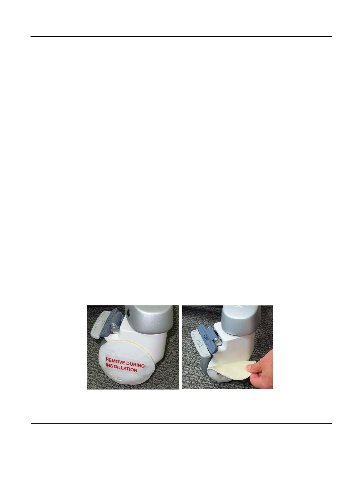
PRELIMINARY
GE
P
ART NUMBER FN091065, REVISION 2 VS5 N AND VS6 N SERVICE MANUAL
8 Control Panel up/down release handle:
Enables locking of the control panel in position, or changing the
location of the arm by moving it upwards and away from the user,
or downwards and away from the system. This provides leg room
for the user who may then be seated beside the system.
9 Rear Caster: Enables free rolling and swiveling. On Vivid S6 N systems, also
enables full-locking of swivel motion.
10 Front Caster: Enables full-locking of swivel motion, or free rolling and swiveling.
NOTE: Each Front an d Rear Caster wheel is covered with an adhesive p ad to provide protection and eliminate
the risk of possible damage during shipping. After installation, carefully remove the protective pads from
all casters, as illustrated Figure 3-16, below.
11 ECG Connector: Provides External ECG input connection to an ECG monitor device
outlet, or direct patient three-contact ECG lead connection.
Important: Do not use the Vivid 7 ECG cable with the
Vivid S5 N or Vivid S6 N system.
12 Speakers: Two loudspeakers provided for Doppler sound.
13 Air inlet and Sub woofer: Air flow is via a built-in filter on the side cover, for system air
cooling. A sub-woofer speaker provides superb sound.
14 ON/OFF: Power ON/OFF knob enables the user turn ON the system (when
power is connected and the system is either in Shutdown or
Standby mode).
15 Probe Connectors: Vivid S6 N system
5 active probe connectors
(3 RS probe connectors, one connector for a pencil probe, and one
LOGIQ-type connector for TEE probes).
Vivid S5 N system
4 active probe connectors
(3 RS probe connectors, and one connector for a pencil probe
Figure 3-16 Removing Protective Pad from Caster Wheels
Chapter 3 - System Setup 3-21
Page 98
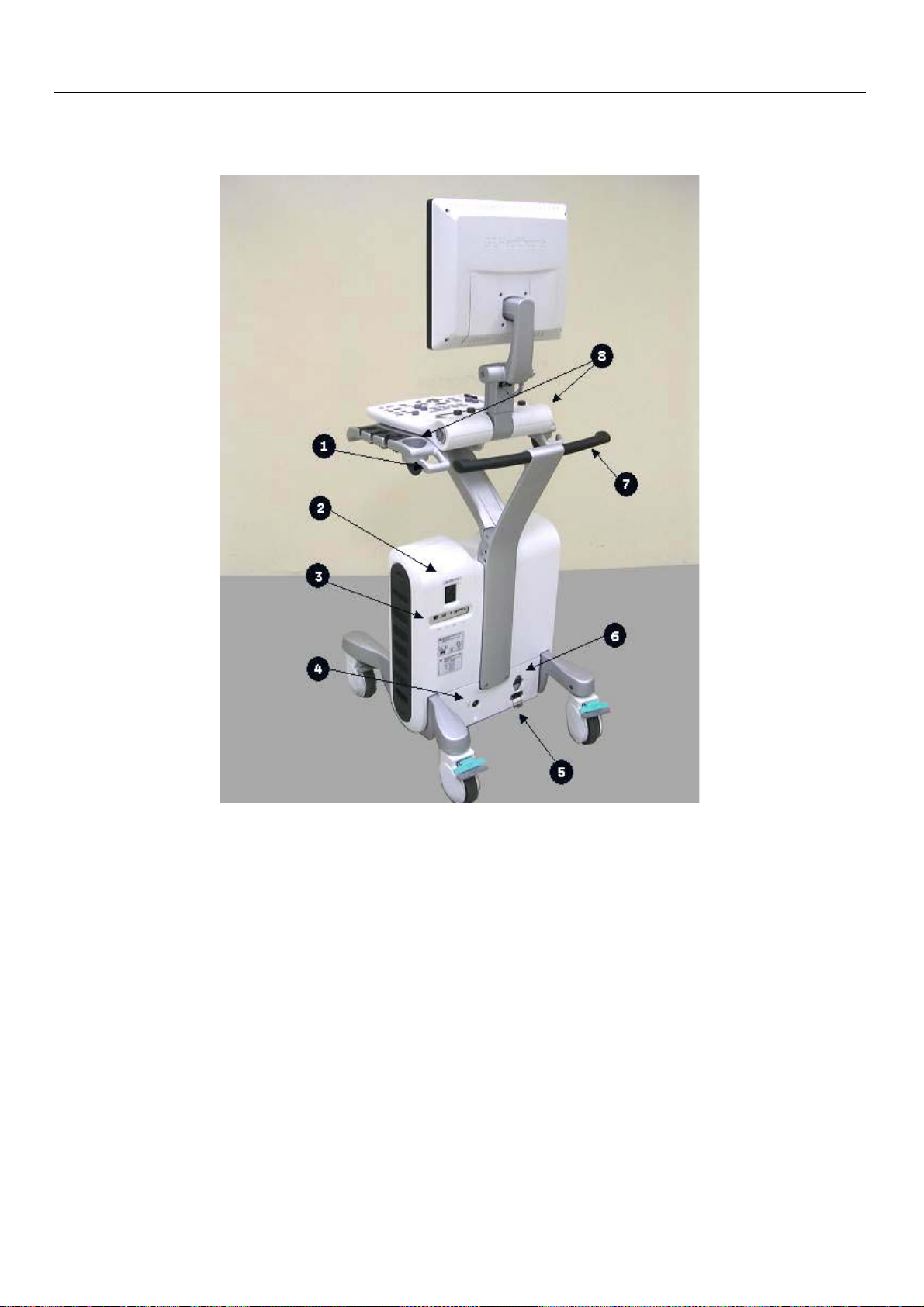
PRELIMINARY
GE
P
ART NUMBER FN091065, REVISION 2 VS5 N AND VS6 N SERVICE MANUAL
3-4-3-3 Rear View of the Vivid S5 N or Vivid S6 N Ultrasound Unit
Figure 3-17 Vivid S5 N or Vivid S6 N Rear View
1
Rear Cable Hooks:Provides a cable management solution for probes and ECG leads.
2
AC Outlet:Two isolated AC outlets for peripherals attached to the scanner.
3
I/O panel:Provides LAN, DVI, Audio and 2 USB 2.0 ports.
4
Ground:Detachable Ground plug.
5
Main AC IN:Main AC input plug, secured by a safety spring.
6
Main Circuit Breaker:Provides power to the scanner.
7
Rear Handle:Used to pull/push the scanner and place it in the desired position.
8
Gel Holders:Provides convenient storage for US Gel bottles. Holders are situated on either side
of the control console, and on the top surface on either side of the monitor.
3-22 Section 3-4 - Preparing for Installation
Page 99
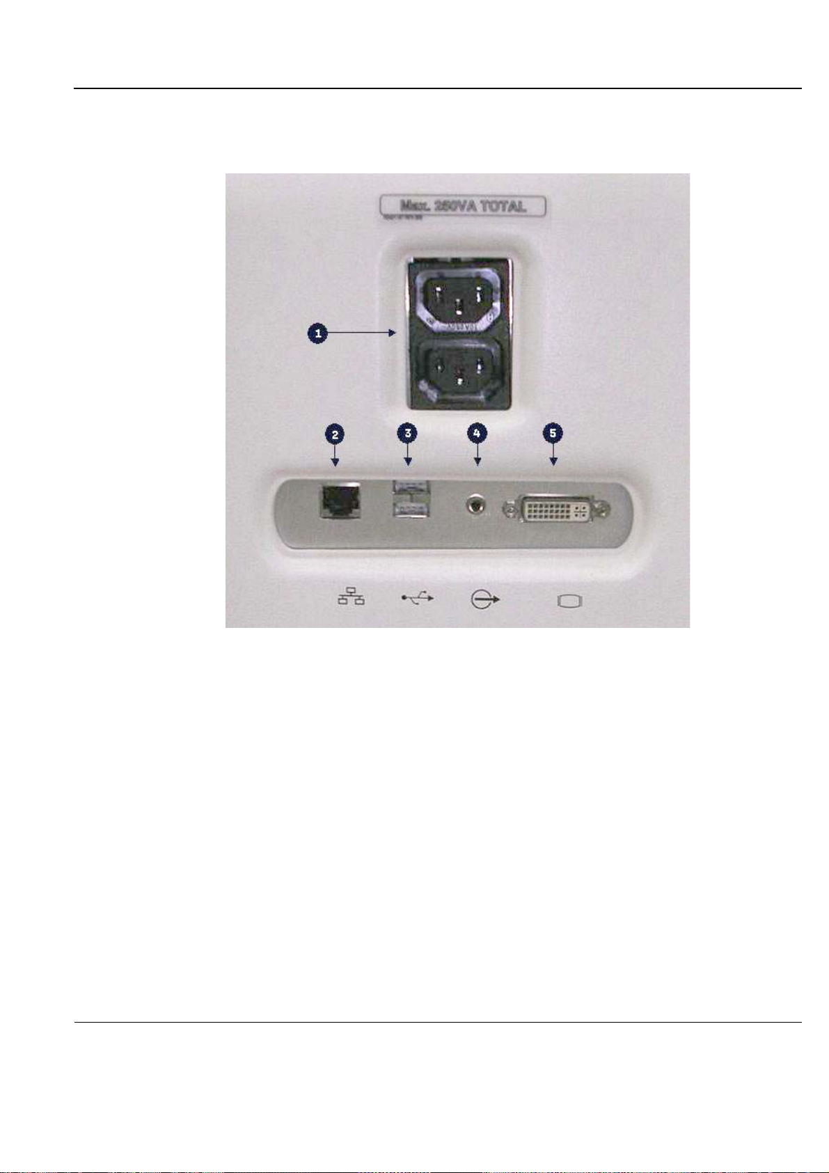
PRELIMINARY
GE
P
ART NUMBER FN091065, REVISION 2 VS5 N AND VS6 N SERVICE MANUAL
3-4-3-4 Rear Panel of the Vivid S5 N or Vivid S6 N Ultrasound Unit
Figure 3-18 shows a view of the Vivid S5 N or Vivid S6 N ultrasound unit rear panel and external
peripheral/accessory connectors:
Figure 3-18 View of the Vivid S5 N or Vivid S6 N Rear Panel
1 Peripherals 230VA AC outlet, isolated - provides power to external peripherals connected to
scanner.
2 LAN 10/100 Base-TX Ethernet network connector.
3 Two interchangeable USB ports (for digital printer, MOD and other peripherals).
4 Audio outlet.
5 DVI Output (VCR option or CRT monitor option).
Chapter 3 - System Setup 3-23
Page 100
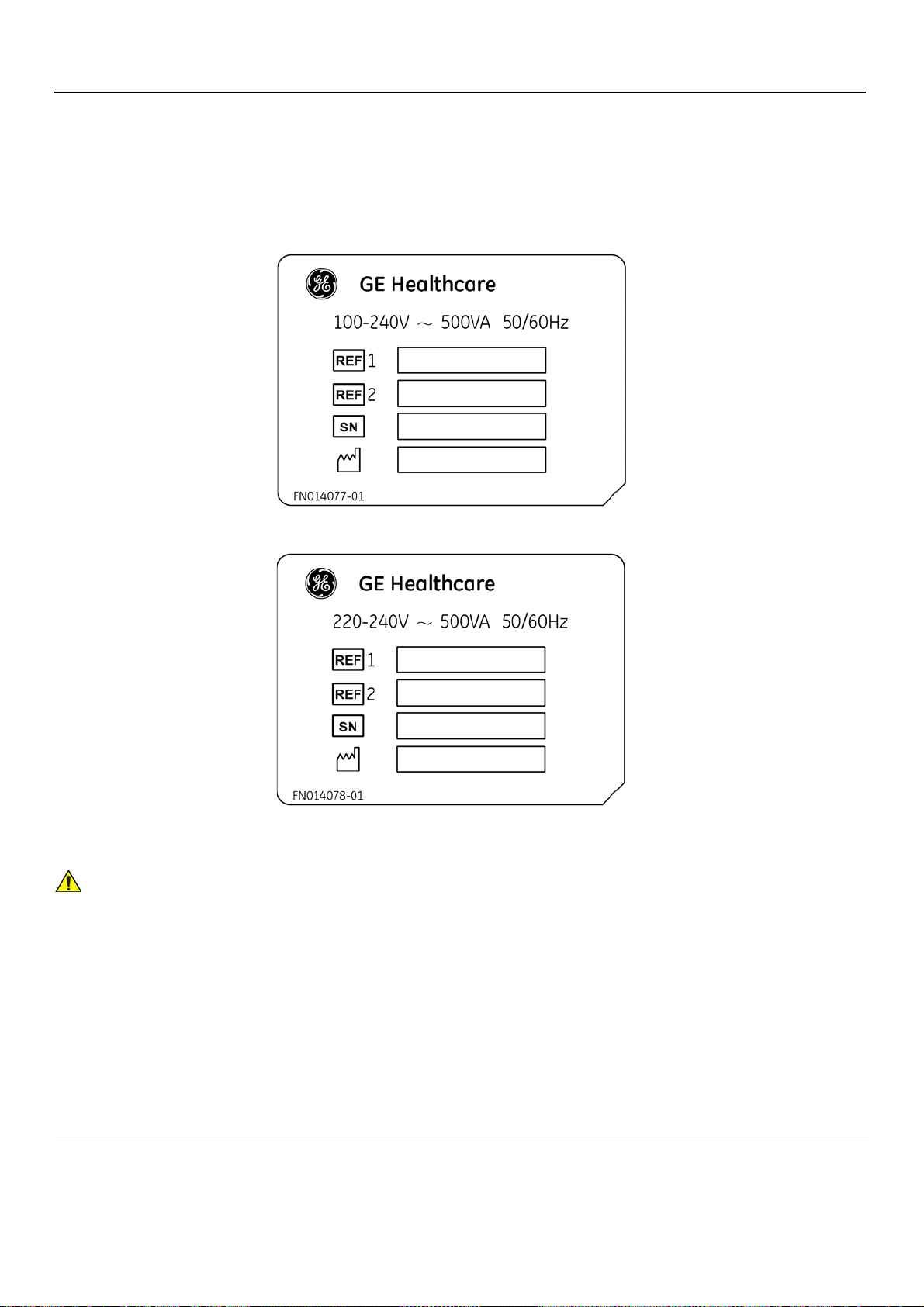
PRELIMINARY
WARNINGWARNING
Systems with Type-B Power Supply:
Systems with Type-A Power Supply:
GE
P
ART NUMBER FN091065, REVISION 2 VS5 N AND VS6 N SERVICE MANUAL
3-4-4 System Voltage Confirmation
3-4-4-1 System Voltage Settings
Verify that the Vivid S5 N or Vivid S6 N ultrasound scanner is set to the correct voltage.
The voltage settings are found on the system rear cover.
Figure 3-19 Safety Rating Plate - Examples
CONNECTING THE UNIT TO THE WRONG VOLTAGE LEVEL WILL MOST LIKELY
DESTROY THE SCANNER.
3-24 Section 3-4 - Preparing for Installation
 Loading...