

Page 1

Technical
Publication
Part Number FC091194
Revision 02
GE Medical Systems
GE Medical Systems
Vivid 7 / Vivid 7 PRO Service Manual
Copyright© 2002 General Electric Co.
All rights reserved
Page 2

Page 3

GE MEDICAL SYSTEMS
DIRECTION FC091194, REVISION 02 VIVID 7 / VIVID 7 PRO SERVICE MANUAL
IMPORTANT PRECAUTIONS
LANGUAGE
• THIS SERVICE MANUAL IS AVAILABLE IN ENGLISH ONLY.
• IF A CUSTOMER’S SERVICE PROVIDER REQUIRES A
LANGUAGE OTHER THAN ENGLISH, IT IS THE CUSTOMER’S
RESPONSIBILITY TO PROVIDE TRANSLATION SERVICES.
WARNING
AVERTISSEMENT
• DO NOT ATTEMPT TO SERVICE THE EQUIPMENT UNLESS THIS
SERVICE MANUAL HAS BEEN CONSULTED AND IS
UNDERSTOOD.
• FAILURE TO HEED THIS WARNING MAY RESULT IN INJURY TO
THE SERVICE PROVIDER, OPERATOR OR PATIENT FROM
ELECTRIC SHOCK, MECHANICAL OR OTHER HAZARDS.
• CE MANUEL DE MAINTENANCE N’EST DISPONIBLE QU’EN
ANGLAIS.
• SI LE TECHNICIEN DU CLIENT A BESOIN DE CE MANUEL DANS
UNE AUTRE LANGUE QUE L’ANGLAIS, C’EST AU CLIENT QU’IL
INCOMBE DE LE FAIRE TRADUIRE.
• NE PAS TENTER D’INTERVENTION SUR LES ÉQUIPEMENTS
TANT QUE LE MANUEL SERVICE N’A PAS ÉTÉ CONSULTÉ ET
COMPRIS.
• LE NON-RESPECT DE CET AVERTISSEMENT PEUT ENTRAÎNER
CHEZ LE TECHNICIEN, L’OPÉRATEUR OU LE PATIENT DES
BLESSURES DUES À DES DANGERS ÉLECTRIQUES,
MÉCANIQUES OU AUTRES.
WARNUNG
• DIESES KUNDENDIENST-HANDBUCH EXISTIERT NUR IN
ENGLISCHER SPRACHE.
• FALLS EIN FREMDER KUNDENDIENST EINE ANDERE SPRACHE
BENÖTIGT, IST ES AUFGABE DES KUNDEN FÜR EINE
ENTSPRECHENDE ÜBERSETZUNG ZU SORGEN.
• VERSUCHEN SIE NICHT, DAS GERÄT ZU REPARIEREN, BEVOR
DIESES KUNDENDIENST-HANDBUCH NICHT ZU RATE
GEZOGEN UND VERSTANDEN WURDE.
• WIRD DIESE WARNUNG NICHT BEACHTET, SO KANN ES ZU
VERLETZUNGEN DES KUNDENDIENSTTECHNIKERS, DES
BEDIENERS ODER DES PATIENTEN DURCH ELEKTRISCHE
SCHLÄGE, MECHANISCHE ODER SONSTIGE GEFAHREN
KOMMEN.
- iii
Page 4

GE MEDICAL SYSTEMS
DIRECTION FC091194, REVISION 02 VIVID 7 / VIVID 7 PRO SERVICE MANUAL
• ESTE MANUAL DE SERVICIO SÓLO EXISTE EN INGLÉS.
• SI ALGÚN PROVEEDOR DE SERVICIOS AJENO A GEMS
SOLICITA UN IDIOMA QUE NO SEA EL INGLÉS, ES
RESPONSABILIDAD DEL CLIENTE OFRECER UN SERVICIO DE
TRADUCCIÓN.
AVISO
• NO SE DEBERÁ DAR SERVICIO TÉCNICO AL EQUIPO, SIN
HABER CONSULTADO Y COMPRENDIDO ESTE MANUAL DE
SERVICIO.
• LA NO OBSERVANCIA DEL PRESENTE AVISO PUEDE DAR
LUGAR A QUE EL PROVEEDOR DE SERVICIOS, EL OPERADOR
O EL PACIENTE SUFRAN LESIONES PROVOCADAS POR
CAUSAS ELÉCTRICAS, MECÁNICAS O DE OTRA NATURALEZA.
• ESTE MANUAL DE ASSISTÊNCIA TÉCNICA SÓ SE ENCONTRA
DISPONÍVEL EM INGLÊS.
• SE QUALQUER OUTRO SERVIÇO DE ASSISTÊNCIA TÉCNICA,
QUE NÃO A GEMS, SOLICITAR ESTES MANUAIS NOUTRO
IDIOMA, É DA RESPONSABILIDADE DO CLIENTE FORNECER
ATENÇÃO
OS SERVIÇOS DE TRADUÇÃO.
• NÃO TENTE REPARAR O EQUIPAMENTO SEM TER
CONSULTADO E COMPREENDIDO ESTE MANUAL DE
ASSISTÊNCIA TÉCNICA.
• O NÃO CUMPRIMENTO DESTE AVISO PODE POR EM PERIGO A
SEGURANÇA DO TÉCNICO, OPERADOR OU PACIENTE DEVIDO
A‘ CHOQUES ELÉTRICOS, MECÂNICOS OU OUTROS.
• IL PRESENTE MANUALE DI MANUTENZIONE È DISPONIBILE
SOLTANTO IN INGLESE.
• SE UN ADDETTO ALLA MANUTENZIONE ESTERNO ALLA GEMS
RICHIEDE IL MANUALE IN UNA LINGUA DIVERSA, IL CLIENTE È
TENUTO A PROVVEDERE DIRETTAMENTE ALLA TRADUZIONE.
• SI PROCEDA ALLA MANUTENZIONE DELL’APPARECCHIATURA
AVVERTENZA
SOLO DOPO AVER CONSULTATO IL PRESENTE MANUALE ED
AVERNE COMPRESO IL CONTENUTO.
• NON TENERE CONTO DELLA PRESENTE AVVERTENZA
POTREBBE FAR COMPIERE OPERAZIONI DA CUI DERIVINO
LESIONI ALL’ADDETTO ALLA MANUTENZIONE,
ALL’UTILIZZATORE ED AL PAZIENTE PER FOLGORAZIONE
ELETTRICA, PER URTI MECCANICI OD ALTRI RISCHI.
iv -
Page 5
GE MEDICAL SYSTEMS
DIRECTION FC091194, REVISION 02 VIVID 7 / VIVID 7 PRO SERVICE MANUAL
DAMAGE IN TRANSPORTATION
(For USA Only)
All packages should be closely examined at time of delivery. If damage is apparent
write “Damage In Shipment” on ALL copies of the freight or express bill BEFORE
delivery is accepted or “signed for” by a GE representative or hospital receiving
agent. Whether noted or concealed, damage MUST be reported to the carrier
immediately upon discovery, or in any event, within 14 days after receipt, and the
contents and containers held for inspection by the carrier. A transportation
company will not pay a claim for damage if an inspection is not requested within
this 14 day period.
For USA Only:
Call Traffic and Transportation, Milwaukee, WI (262) 785-5052 or 8*323 5052
immediately after damage is found. At this time be ready to supply name of carrier,
delivery date, consignee name, freight or express bill number, item damaged and
extent of damage.
For USA Only:
Complete instructions regarding claim procedure are found in Section S of the
Policy And Procedures Bulletins.
14 July 1993
- v
Page 6

GE MEDICAL SYSTEMS
DIRECTION FC091194, REVISION 02 VIVID 7 / VIVID 7 PRO SERVICE MANUAL
CERTIFIED ELECTRICAL CONTRACTOR STATEMENT
(For USA Only)
All electrical Installations that are preliminary to positioning of the equipment at the
site prepared for the equipment shall be performed by licensed electrical
contractors. Other connections between pieces of electrical equipment,
calibrations and testing shall be performed by qualified GE Medical personnel. In
performing all electrical work on these products, GE will use its own specially
trained field engineers. All of GE’s electrical work on these products will comply
with the requirements of the applicable electrical codes.
The purchaser of GE equipment shall only utilize qualified personnel (i.e., GE’s
field engineers, personnel of third-party service companies with equivalent training,
or licensed electricians) to perform electrical servicing on the equipment.
OMISSIONS & ERRORS
If there are any omissions, errors or suggestions for improving this documentation,
please contact the GE Medical Systems Global Documentation Group with specific
information listing the system type, manual title, part number, revision number,
page number and suggestion details. E-mail the information to :
UltrasoundDocError@med.ge.com
GE Medical Systems employees should use the Customer Quality Assurance
(CQA) System to report all documentation omissions, errors or suggestions.
vi -
Page 7

GE MEDICAL SYSTEMS
DIRECTION FC091194, REVISION 02 VIVID 7 / VIVID 7 PRO SERVICE MANUAL
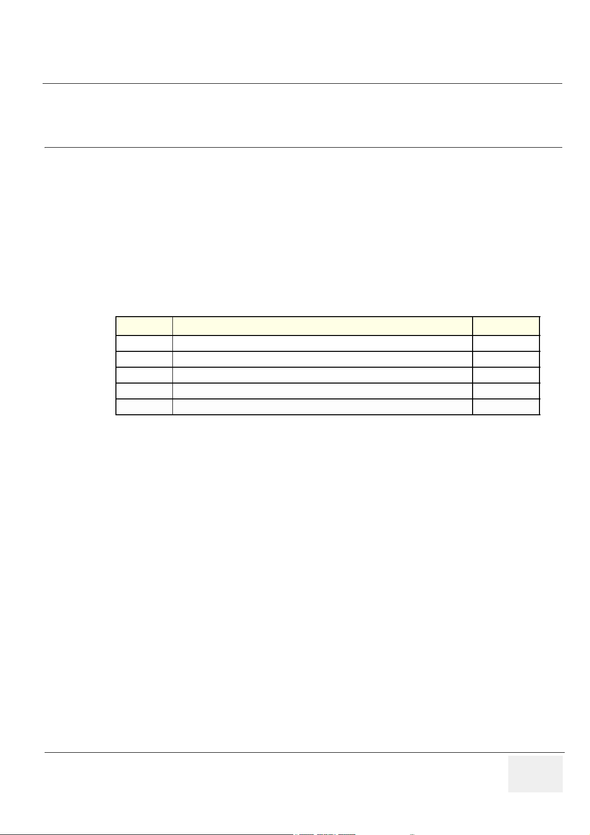
Revision History
REVISION DATE REASON FOR CHANGE
01
02
11. JUN. 2002
30. AUG. 2002 Updated per BT02-M4 release. Included description for BEP-2.
Covers both Vivid 7 and Vivid 7 PRO
Replaces Vivid 7 Service Manual, Part Number FB091202
- vii
Page 8

GE MEDICAL SYSTEMS
DIRECTION FC091194, REVISION 02 VIVID 7 / VIVID 7 PRO SERVICE MANUAL
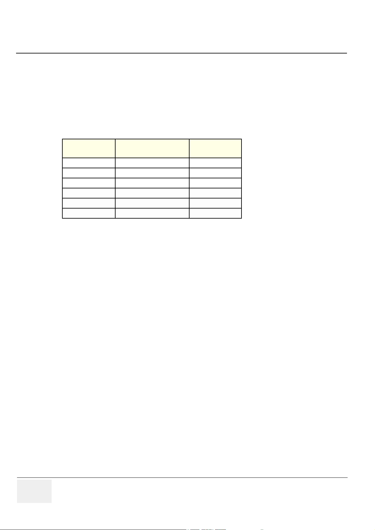
List of Effected Pages
Pages Revision Pages Revision Pages Revision
Title Page 02 4-1 to 4-66 02 9-1 to 9-37 02
Warnings
iii to vi
Rev History/LOEP
vii to viii
1-1 to 1-40 02 7-1 to 7-70 02
2-1 to 2-12 02 8-1 to 8-56 02
3-1 to 3-58 02
02 5-1 to 5-104 02 10-1 to 10-26 02
02 6-1 to 6-8 02 Back Cover N/A
viii -
Page 9

GE MEDICAL SYSTEMS
D
IRECTION FC091194, REVISION 02 VIVID 7 / VIVID 7 PRO SERVICE MANUAL
Table of Contents
CHAPTER 1
Introduction
Overview . . . . . . . . . . . . . . . . . . . . . . . . . . . . . . . . . . . . . . . . . . . . . . . . . . . . . . . . . 1 - 1
Purpose of Chapter 1 . . . . . . . . . . . . . . . . . . . . . . . . . . . . . . . . . . . . . . . . . . 1 - 1
Purpose of Service Manual . . . . . . . . . . . . . . . . . . . . . . . . . . . . . . . . . . . . . 1 - 1
Typical Users of the Service Manual . . . . . . . . . . . . . . . . . . . . . . . . . . . . . . 1 - 2
Vivid 7 / Vivid 7 PRO Models Covered by this Manual . . . . . . . . . . . . . . . . 1 - 2
Purpose of Operator Manual(s) . . . . . . . . . . . . . . . . . . . . . . . . . . . . . . . . . . 1 - 7
Important Conventions. . . . . . . . . . . . . . . . . . . . . . . . . . . . . . . . . . . . . . . . . . . . . . . 1 - 8
Conventions Used in Book . . . . . . . . . . . . . . . . . . . . . . . . . . . . . . . . . . . . . . 1 - 8
Standard Hazard Icons . . . . . . . . . . . . . . . . . . . . . . . . . . . . . . . . . . . . . . . . 1 - 9
Product Icons . . . . . . . . . . . . . . . . . . . . . . . . . . . . . . . . . . . . . . . . . . . . . . . . 1 - 10
Safety Considerations . . . . . . . . . . . . . . . . . . . . . . . . . . . . . . . . . . . . . . . . . . . . . . . 1 - 12
Introduction . . . . . . . . . . . . . . . . . . . . . . . . . . . . . . . . . . . . . . . . . . . . . . . . . 1 - 12
Human Safety . . . . . . . . . . . . . . . . . . . . . . . . . . . . . . . . . . . . . . . . . . . . . . . 1 - 12
Mechanical Safety . . . . . . . . . . . . . . . . . . . . . . . . . . . . . . . . . . . . . . . . . . . . 1 - 12
Electrical Safety . . . . . . . . . . . . . . . . . . . . . . . . . . . . . . . . . . . . . . . . . . . . . . 1 - 13
Labels Locations . . . . . . . . . . . . . . . . . . . . . . . . . . . . . . . . . . . . . . . . . . . . . 1 - 14
Dangerous Procedure Warnings . . . . . . . . . . . . . . . . . . . . . . . . . . . . . . . . . 1 - 36
Lockout/Tagout Requirements (For USA Only) . . . . . . . . . . . . . . . . . . . . . . 1 - 36
EMC, EMI, and ESD . . . . . . . . . . . . . . . . . . . . . . . . . . . . . . . . . . . . . . . . . . . . . . . . 1 - 37
Electromagnetic Compatibility (EMC) and Interference (EMI) . . . . . . . . . . . 1 - 37
CE Compliance . . . . . . . . . . . . . . . . . . . . . . . . . . . . . . . . . . . . . . . . . . . . . . 1 - 37
Electrostatic Discharge (ESD) Prevention . . . . . . . . . . . . . . . . . . . . . . . . . . 1 - 37
Customer Assistance. . . . . . . . . . . . . . . . . . . . . . . . . . . . . . . . . . . . . . . . . . . . . . . . 1 - 38
Contact Information . . . . . . . . . . . . . . . . . . . . . . . . . . . . . . . . . . . . . . . . . . . 1 - 38
System Manufacture . . . . . . . . . . . . . . . . . . . . . . . . . . . . . . . . . . . . . . . . . . 1 - 39
Table of Contents ix
Page 10

GE MEDICAL SYSTEMS
D
IRECTION FC091194, REVISION 02 VIVID 7 / VIVID 7 PRO SERVICE MANUAL
CHAPTER 2
Pre-Installation
Overview . . . . . . . . . . . . . . . . . . . . . . . . . . . . . . . . . . . . . . . . . . . . . . . . . . . . . . . . . 2 - 1
Purpose of Chapter 2 . . . . . . . . . . . . . . . . . . . . . . . . . . . . . . . . . . . . . . . . . . 2 - 1
General Console Requirements. . . . . . . . . . . . . . . . . . . . . . . . . . . . . . . . . . . . . . . . 2 - 2
Console Environmental Requirements . . . . . . . . . . . . . . . . . . . . . . . . . . . . . 2 - 2
Electrical Requirements . . . . . . . . . . . . . . . . . . . . . . . . . . . . . . . . . . . . . . . . 2 - 3
EMI Limitations . . . . . . . . . . . . . . . . . . . . . . . . . . . . . . . . . . . . . . . . . . . . . . . 2 - 4
Probes Environmental Requirements . . . . . . . . . . . . . . . . . . . . . . . . . . . . . 2 - 6
Time and Manpower Requirements . . . . . . . . . . . . . . . . . . . . . . . . . . . . . . . 2 - 6
Facility Needs . . . . . . . . . . . . . . . . . . . . . . . . . . . . . . . . . . . . . . . . . . . . . . . . . . . . . 2 - 7
Purchaser Responsibilities . . . . . . . . . . . . . . . . . . . . . . . . . . . . . . . . . . . . . . 2 - 7
Required Facility Needs . . . . . . . . . . . . . . . . . . . . . . . . . . . . . . . . . . . . . . . . 2 - 8
Desirable Features . . . . . . . . . . . . . . . . . . . . . . . . . . . . . . . . . . . . . . . . . . . . 2 - 9
Minimal Floor Plan Suggestion . . . . . . . . . . . . . . . . . . . . . . . . . . . . . . . . . . 2 - 9
Networking Pre-installation Requirements . . . . . . . . . . . . . . . . . . . . . . . . . . 2 - 10
x Table of Contents
Page 11

GE MEDICAL SYSTEMS
D
IRECTION FC091194, REVISION 02 VIVID 7 / VIVID 7 PRO SERVICE MANUAL
CHAPTER 3
Installation
Overview. . . . . . . . . . . . . . . . . . . . . . . . . . . . . . . . . . . . . . . . . . . . . . . . . . . . . . . . . 3 - 1
Purpose of Chapter 3 . . . . . . . . . . . . . . . . . . . . . . . . . . . . . . . . . . . . . . . . . 3 - 1
Installation Reminders . . . . . . . . . . . . . . . . . . . . . . . . . . . . . . . . . . . . . . . . . . . . . . 3 - 1
Average Installation Time . . . . . . . . . . . . . . . . . . . . . . . . . . . . . . . . . . . . . . 3 - 1
Installation Warnings . . . . . . . . . . . . . . . . . . . . . . . . . . . . . . . . . . . . . . . . . 3 - 2
Receiving and Unpacking the Equipment. . . . . . . . . . . . . . . . . . . . . . . . . . . . . . . . 3 - 3
Introduction . . . . . . . . . . . . . . . . . . . . . . . . . . . . . . . . . . . . . . . . . . . . . . . . . 3 - 3
Receiving Vivid 7 / Vivid 7 PRO . . . . . . . . . . . . . . . . . . . . . . . . . . . . . . . . . . . . . . . 3 - 4
Introduction . . . . . . . . . . . . . . . . . . . . . . . . . . . . . . . . . . . . . . . . . . . . . . . . . 3 - 4
Unpacking Vivid 7 / Vivid 7 PRO . . . . . . . . . . . . . . . . . . . . . . . . . . . . . . . . . . . . . . 3 - 5
Transportation Box Dimensions . . . . . . . . . . . . . . . . . . . . . . . . . . . . . . . . . 3 - 7
Preparing for Installation. . . . . . . . . . . . . . . . . . . . . . . . . . . . . . . . . . . . . . . . . . . . . 3 - 8
Physical Inspection . . . . . . . . . . . . . . . . . . . . . . . . . . . . . . . . . . . . . . . . . . . 3 - 8
EMI Protection . . . . . . . . . . . . . . . . . . . . . . . . . . . . . . . . . . . . . . . . . . . . . . 3 - 8
Completing the Installation . . . . . . . . . . . . . . . . . . . . . . . . . . . . . . . . . . . . . . . . . . . 3 - 8
System Specifications . . . . . . . . . . . . . . . . . . . . . . . . . . . . . . . . . . . . . . . . . 3 - 8
Electrical Specifications . . . . . . . . . . . . . . . . . . . . . . . . . . . . . . . . . . . . . . . 3 - 9
Connect Footswitch . . . . . . . . . . . . . . . . . . . . . . . . . . . . . . . . . . . . . . . . . . 3 - 10
Connect Telephone Line to Modem Connector . . . . . . . . . . . . . . . . . . . . . 3 - 10
Connect ECG . . . . . . . . . . . . . . . . . . . . . . . . . . . . . . . . . . . . . . . . . . . . . . . 3 - 11
Connect Phono . . . . . . . . . . . . . . . . . . . . . . . . . . . . . . . . . . . . . . . . . . . . . . 3 - 11
Connect Pulse Pressure Transducer . . . . . . . . . . . . . . . . . . . . . . . . . . . . . 3 - 12
Connect Ethernet . . . . . . . . . . . . . . . . . . . . . . . . . . . . . . . . . . . . . . . . . . . . 3 - 12
Probe Connection . . . . . . . . . . . . . . . . . . . . . . . . . . . . . . . . . . . . . . . . . . . . 3 - 13
Power ON/Boot Up . . . . . . . . . . . . . . . . . . . . . . . . . . . . . . . . . . . . . . . . . . . 3 - 14
Power Shut Down . . . . . . . . . . . . . . . . . . . . . . . . . . . . . . . . . . . . . . . . . . . . 3 - 17
Switching OFF the Unit . . . . . . . . . . . . . . . . . . . . . . . . . . . . . . . . . . . . . . . . 3 - 17
Configuration . . . . . . . . . . . . . . . . . . . . . . . . . . . . . . . . . . . . . . . . . . . . . . . . . . . . . 3 - 21
Vivid 7 / Vivid 7 PRO Configuration . . . . . . . . . . . . . . . . . . . . . . . . . . . . . . 3 - 22
Service Screen . . . . . . . . . . . . . . . . . . . . . . . . . . . . . . . . . . . . . . . . . . . . . . 3 - 28
Optional Peripherals/Peripheral Connection . . . . . . . . . . . . . . . . . . . . . . . . 3 - 32
Available Probes . . . . . . . . . . . . . . . . . . . . . . . . . . . . . . . . . . . . . . . . . . . . . 3 - 32
Video Specification . . . . . . . . . . . . . . . . . . . . . . . . . . . . . . . . . . . . . . . . . . . 3 - 32
Table of Contents xi
Page 12

GE MEDICAL SYSTEMS
D
IRECTION FC091194, REVISION 02 VIVID 7 / VIVID 7 PRO SERVICE MANUAL
Software Options Configuration . . . . . . . . . . . . . . . . . . . . . . . . . . . . . . . . . . 3 - 33
Connectivity . . . . . . . . . . . . . . . . . . . . . . . . . . . . . . . . . . . . . . . . . . . . . . . . . . . . . . . 3 - 35
Introduction . . . . . . . . . . . . . . . . . . . . . . . . . . . . . . . . . . . . . . . . . . . . . . . . . 3 - 35
Physical Connection . . . . . . . . . . . . . . . . . . . . . . . . . . . . . . . . . . . . . . . . . . . 3 - 35
Connectivity Setup . . . . . . . . . . . . . . . . . . . . . . . . . . . . . . . . . . . . . . . . . . . . 3 - 37
Installation Paperwork . . . . . . . . . . . . . . . . . . . . . . . . . . . . . . . . . . . . . . . . . . . . . . . 3 - 56
User Manual(s) . . . . . . . . . . . . . . . . . . . . . . . . . . . . . . . . . . . . . . . . . . . . . . . 3 - 56
Complete the Post Delivery Check List . . . . . . . . . . . . . . . . . . . . . . . . . . . . 3 - 56
Post Delivery Check List . . . . . . . . . . . . . . . . . . . . . . . . . . . . . . . . . . . . . . . 3 - 57
xii Table of Contents
Page 13

GE MEDICAL SYSTEMS
D
IRECTION FC091194, REVISION 02 VIVID 7 / VIVID 7 PRO SERVICE MANUAL
CHAPTER 4
Functional Checks
Overview. . . . . . . . . . . . . . . . . . . . . . . . . . . . . . . . . . . . . . . . . . . . . . . . . . . . . . . . . 4 - 1
Purpose of Chapter 4 . . . . . . . . . . . . . . . . . . . . . . . . . . . . . . . . . . . . . . . . . 4 - 1
Special Equipment Required . . . . . . . . . . . . . . . . . . . . . . . . . . . . . . . . . . . 4 - 1
General Procedures . . . . . . . . . . . . . . . . . . . . . . . . . . . . . . . . . . . . . . . . . . . . . . . . 4 - 2
Power ON/ Boot Up . . . . . . . . . . . . . . . . . . . . . . . . . . . . . . . . . . . . . . . . . . 4 - 2
Power Shut Down . . . . . . . . . . . . . . . . . . . . . . . . . . . . . . . . . . . . . . . . . . . . 4 - 5
Using Removable Media . . . . . . . . . . . . . . . . . . . . . . . . . . . . . . . . . . . . . . . 4 - 9
Labeling Removable Media . . . . . . . . . . . . . . . . . . . . . . . . . . . . . . . . . . . . 4 - 10
Formatting Removable Media . . . . . . . . . . . . . . . . . . . . . . . . . . . . . . . . . . . 4 - 11
Verifying Removable Media . . . . . . . . . . . . . . . . . . . . . . . . . . . . . . . . . . . . 4 - 11
Archiving and Loading Presets . . . . . . . . . . . . . . . . . . . . . . . . . . . . . . . . . . 4 - 12
Functional Checks . . . . . . . . . . . . . . . . . . . . . . . . . . . . . . . . . . . . . . . . . . . . . . . . . 4 - 14
Preparation . . . . . . . . . . . . . . . . . . . . . . . . . . . . . . . . . . . . . . . . . . . . . . . . . 4 - 14
Basic Controls . . . . . . . . . . . . . . . . . . . . . . . . . . . . . . . . . . . . . . . . . . . . . . . 4 - 14
Performance Tests . . . . . . . . . . . . . . . . . . . . . . . . . . . . . . . . . . . . . . . . . . . 4 - 16
2D Mode (B mode) Checks . . . . . . . . . . . . . . . . . . . . . . . . . . . . . . . . . . . . 4 - 17
M Mode Checks . . . . . . . . . . . . . . . . . . . . . . . . . . . . . . . . . . . . . . . . . . . . . 4 - 24
Color Mode Checks . . . . . . . . . . . . . . . . . . . . . . . . . . . . . . . . . . . . . . . . . . 4 - 28
Doppler Mode Checks . . . . . . . . . . . . . . . . . . . . . . . . . . . . . . . . . . . . . . . . 4 - 34
Tissue Velocity Imaging (TVI) Checks . . . . . . . . . . . . . . . . . . . . . . . . . . . . 4 - 40
Contrast Checks . . . . . . . . . . . . . . . . . . . . . . . . . . . . . . . . . . . . . . . . . . . . . 4 - 46
Stress Echo . . . . . . . . . . . . . . . . . . . . . . . . . . . . . . . . . . . . . . . . . . . . . . . . 4 - 46
Measurements and Multi Image Checks . . . . . . . . . . . . . . . . . . . . . . . . . . 4 - 47
Multi Image Checks . . . . . . . . . . . . . . . . . . . . . . . . . . . . . . . . . . . . . . . . . . 4 - 49
Probe/Connectors Check . . . . . . . . . . . . . . . . . . . . . . . . . . . . . . . . . . . . . . 4 - 50
ECG Check . . . . . . . . . . . . . . . . . . . . . . . . . . . . . . . . . . . . . . . . . . . . . . . . . 4 - 51
Cineloop Check . . . . . . . . . . . . . . . . . . . . . . . . . . . . . . . . . . . . . . . . . . . . . 4 - 52
Backend Processor Checks . . . . . . . . . . . . . . . . . . . . . . . . . . . . . . . . . . . . 4 - 56
Peripheral Checks . . . . . . . . . . . . . . . . . . . . . . . . . . . . . . . . . . . . . . . . . . . 4 - 57
Mechanical Functions Checks . . . . . . . . . . . . . . . . . . . . . . . . . . . . . . . . . . 4 - 61
Application Turnover Check List . . . . . . . . . . . . . . . . . . . . . . . . . . . . . . . . . . . . . . . 4 - 63
Software Configuration Checks . . . . . . . . . . . . . . . . . . . . . . . . . . . . . . . . . 4 - 63
Power Supply . . . . . . . . . . . . . . . . . . . . . . . . . . . . . . . . . . . . . . . . . . . . . . . . . . . . . 4 - 64
Power Supply Test Procedure . . . . . . . . . . . . . . . . . . . . . . . . . . . . . . . . . . 4 - 64
Power Supply Adjustment . . . . . . . . . . . . . . . . . . . . . . . . . . . . . . . . . . . . . . 4 - 64
Table of Contents xiii
Page 14

GE MEDICAL SYSTEMS
D
IRECTION FC091194, REVISION 02 VIVID 7 / VIVID 7 PRO SERVICE MANUAL
Site Log . . . . . . . . . . . . . . . . . . . . . . . . . . . . . . . . . . . . . . . . . . . . . . . . . . . . . . . . . . 4 - 65
xiv Table of Contents
Page 15

GE MEDICAL SYSTEMS
D
IRECTION FC091194, REVISION 02 VIVID 7 / VIVID 7 PRO SERVICE MANUAL
CHAPTER 5
Components and Functions (Theory)
Overview. . . . . . . . . . . . . . . . . . . . . . . . . . . . . . . . . . . . . . . . . . . . . . . . . . . . . . . . . 5 - 1
Purpose of Chapter 5 . . . . . . . . . . . . . . . . . . . . . . . . . . . . . . . . . . . . . . . . . 5 - 1
General Information . . . . . . . . . . . . . . . . . . . . . . . . . . . . . . . . . . . . . . . . . . . . . . . . 5 - 2
Block Diagram . . . . . . . . . . . . . . . . . . . . . . . . . . . . . . . . . . . . . . . . . . . . . . 5 - 3
Front End Processor. . . . . . . . . . . . . . . . . . . . . . . . . . . . . . . . . . . . . . . . . . . . . . . . 5 - 4
General Information . . . . . . . . . . . . . . . . . . . . . . . . . . . . . . . . . . . . . . . . . . 5 - 4
Front End Bus . . . . . . . . . . . . . . . . . . . . . . . . . . . . . . . . . . . . . . . . . . . . . . . 5 - 4
Phased and Linear Array Front End . . . . . . . . . . . . . . . . . . . . . . . . . . . . . . 5 - 4
Transmitter Power Supply . . . . . . . . . . . . . . . . . . . . . . . . . . . . . . . . . . . . . 5 - 5
Mid Processors . . . . . . . . . . . . . . . . . . . . . . . . . . . . . . . . . . . . . . . . . . . . . . 5 - 5
Major Sub-Systems in Vivid 7 / Vivid 7 PRO . . . . . . . . . . . . . . . . . . . . . . . 5 - 11
Front End Subsystem . . . . . . . . . . . . . . . . . . . . . . . . . . . . . . . . . . . . . . . . . 5 - 12
Mid Processors . . . . . . . . . . . . . . . . . . . . . . . . . . . . . . . . . . . . . . . . . . . . . . 5 - 13
Back End Processor. . . . . . . . . . . . . . . . . . . . . . . . . . . . . . . . . . . . . . . . . . . . . . . . 5 - 14
Introduction . . . . . . . . . . . . . . . . . . . . . . . . . . . . . . . . . . . . . . . . . . . . . . . . . 5 - 14
Signal Flow and Processing . . . . . . . . . . . . . . . . . . . . . . . . . . . . . . . . . . . . 5 - 14
Location of the Back End Processor . . . . . . . . . . . . . . . . . . . . . . . . . . . . . . 5 - 14
BEP-1 Block Diagram . . . . . . . . . . . . . . . . . . . . . . . . . . . . . . . . . . . . . . . . . 5 - 15
BEP-1 Description . . . . . . . . . . . . . . . . . . . . . . . . . . . . . . . . . . . . . . . . . . . 5 - 16
BEP-2 Block Diagram . . . . . . . . . . . . . . . . . . . . . . . . . . . . . . . . . . . . . . . . . 5 - 17
BEP-2 Description . . . . . . . . . . . . . . . . . . . . . . . . . . . . . . . . . . . . . . . . . . . 5 - 18
PCVIC Card . . . . . . . . . . . . . . . . . . . . . . . . . . . . . . . . . . . . . . . . . . . . . . . . 5 - 19
UPS Battery Operation . . . . . . . . . . . . . . . . . . . . . . . . . . . . . . . . . . . . . . . . 5 - 19
Internal Storage Devices: . . . . . . . . . . . . . . . . . . . . . . . . . . . . . . . . . . . . . . 5 - 20
Inputs . . . . . . . . . . . . . . . . . . . . . . . . . . . . . . . . . . . . . . . . . . . . . . . . . . . . . 5 - 20
Outputs . . . . . . . . . . . . . . . . . . . . . . . . . . . . . . . . . . . . . . . . . . . . . . . . . . . . 5 - 22
Patient I/O (Physio) . . . . . . . . . . . . . . . . . . . . . . . . . . . . . . . . . . . . . . . . . . . . . . . . 5 - 23
Internal I/O . . . . . . . . . . . . . . . . . . . . . . . . . . . . . . . . . . . . . . . . . . . . . . . . . . . . . . . 5 - 24
Location in the Unit . . . . . . . . . . . . . . . . . . . . . . . . . . . . . . . . . . . . . . . . . . . 5 - 26
LEDs . . . . . . . . . . . . . . . . . . . . . . . . . . . . . . . . . . . . . . . . . . . . . . . . . . . . . . 5 - 26
Fuses . . . . . . . . . . . . . . . . . . . . . . . . . . . . . . . . . . . . . . . . . . . . . . . . . . . . . 5 - 26
Jumpers and Dip-switches . . . . . . . . . . . . . . . . . . . . . . . . . . . . . . . . . . . . . 5 - 26
Inputs . . . . . . . . . . . . . . . . . . . . . . . . . . . . . . . . . . . . . . . . . . . . . . . . . . . . . 5 - 27
Outputs . . . . . . . . . . . . . . . . . . . . . . . . . . . . . . . . . . . . . . . . . . . . . . . . . . . . 5 - 29
Table of Contents xv
Page 16

GE MEDICAL SYSTEMS
D
IRECTION FC091194, REVISION 02 VIVID 7 / VIVID 7 PRO SERVICE MANUAL
Top Console. . . . . . . . . . . . . . . . . . . . . . . . . . . . . . . . . . . . . . . . . . . . . . . . . . . . . . . 5 - 31
Peripherals. . . . . . . . . . . . . . . . . . . . . . . . . . . . . . . . . . . . . . . . . . . . . . . . . . . . . . . . 5 - 32
On-board Peripherals . . . . . . . . . . . . . . . . . . . . . . . . . . . . . . . . . . . . . . . . . . 5 - 32
External Peripherals . . . . . . . . . . . . . . . . . . . . . . . . . . . . . . . . . . . . . . . . . . . 5 - 32
Modem . . . . . . . . . . . . . . . . . . . . . . . . . . . . . . . . . . . . . . . . . . . . . . . . . . . . . . . . . . . 5 - 33
Power Distribution . . . . . . . . . . . . . . . . . . . . . . . . . . . . . . . . . . . . . . . . . . . . . . . . . . 5 - 34
Overall AC Power Distribution . . . . . . . . . . . . . . . . . . . . . . . . . . . . . . . . . . . 5 - 34
Overview . . . . . . . . . . . . . . . . . . . . . . . . . . . . . . . . . . . . . . . . . . . . . . . . . . . 5 - 35
AC Power Distribution Box (PWB) . . . . . . . . . . . . . . . . . . . . . . . . . . . . . . . . 5 - 35
DC Power . . . . . . . . . . . . . . . . . . . . . . . . . . . . . . . . . . . . . . . . . . . . . . . . . . . 5 - 37
TX Power Supply . . . . . . . . . . . . . . . . . . . . . . . . . . . . . . . . . . . . . . . . . . . . . 5 - 41
Circuit Boards . . . . . . . . . . . . . . . . . . . . . . . . . . . . . . . . . . . . . . . . . . . . . . . . . . . . . 5 - 44
Overview . . . . . . . . . . . . . . . . . . . . . . . . . . . . . . . . . . . . . . . . . . . . . . . . . . . 5 - 44
Relay Board, RLY . . . . . . . . . . . . . . . . . . . . . . . . . . . . . . . . . . . . . . . . . . . . 5 - 45
Transmitter Board, TX128 . . . . . . . . . . . . . . . . . . . . . . . . . . . . . . . . . . . . . . 5 - 47
Receiver Board, RX-128 . . . . . . . . . . . . . . . . . . . . . . . . . . . . . . . . . . . . . . . 5 - 50
Beamformer Board(s), BF-64 . . . . . . . . . . . . . . . . . . . . . . . . . . . . . . . . . . . . 5 - 53
Front End Controller Board, FEC-2 . . . . . . . . . . . . . . . . . . . . . . . . . . . . . . . 5 - 56
Transducer Bus Boards, XD BUS Boards . . . . . . . . . . . . . . . . . . . . . . . . . . 5 - 61
RF & Tissue Processor Board, RFT . . . . . . . . . . . . . . . . . . . . . . . . . . . . . . . 5 - 62
Spectrum Doppler Processor Board, SDP . . . . . . . . . . . . . . . . . . . . . . . . . . 5 - 66
Image Port 2 Board, IMP2 . . . . . . . . . . . . . . . . . . . . . . . . . . . . . . . . . . . . . . 5 - 70
Backend Processor . . . . . . . . . . . . . . . . . . . . . . . . . . . . . . . . . . . . . . . . . . . 5 - 74
Patient I/O . . . . . . . . . . . . . . . . . . . . . . . . . . . . . . . . . . . . . . . . . . . . . . . . . . 5 - 78
Internal I/O . . . . . . . . . . . . . . . . . . . . . . . . . . . . . . . . . . . . . . . . . . . . . . . . . . 5 - 79
External I/O . . . . . . . . . . . . . . . . . . . . . . . . . . . . . . . . . . . . . . . . . . . . . . . . . 5 - 87
Interconnect Cabling . . . . . . . . . . . . . . . . . . . . . . . . . . . . . . . . . . . . . . . . . . 5 - 90
Motherboard (Back Plane) . . . . . . . . . . . . . . . . . . . . . . . . . . . . . . . . . . . . . . 5 - 92
Modem . . . . . . . . . . . . . . . . . . . . . . . . . . . . . . . . . . . . . . . . . . . . . . . . . . . . . 5 - 93
Video Specifications. . . . . . . . . . . . . . . . . . . . . . . . . . . . . . . . . . . . . . . . . . . . . . . . . 5 - 95
PAL . . . . . . . . . . . . . . . . . . . . . . . . . . . . . . . . . . . . . . . . . . . . . . . . . . . . . . . 5 - 95
NTSC . . . . . . . . . . . . . . . . . . . . . . . . . . . . . . . . . . . . . . . . . . . . . . . . . . . . . . 5 - 95
System Logs . . . . . . . . . . . . . . . . . . . . . . . . . . . . . . . . . . . . . . . . . . . . . . . . . . . . . . 5 - 95
Board Rack Cooling System . . . . . . . . . . . . . . . . . . . . . . . . . . . . . . . . . . . . . . . . . . 5 - 96
General Description . . . . . . . . . . . . . . . . . . . . . . . . . . . . . . . . . . . . . . . . . . . 5 - 96
Location in the Unit . . . . . . . . . . . . . . . . . . . . . . . . . . . . . . . . . . . . . . . . . . . 5 - 96
xvi Table of Contents
Page 17

GE MEDICAL SYSTEMS
D
IRECTION FC091194, REVISION 02 VIVID 7 / VIVID 7 PRO SERVICE MANUAL
Top Console Movement . . . . . . . . . . . . . . . . . . . . . . . . . . . . . . . . . . . . . . . . . . . . . 5 - 97
General Description Vivid 7 . . . . . . . . . . . . . . . . . . . . . . . . . . . . . . . . . . . . 5 - 97
Transportation of Vivid 7 / Vivid 7 PRO . . . . . . . . . . . . . . . . . . . . . . . . . . . 5 - 97
Location in the Unit . . . . . . . . . . . . . . . . . . . . . . . . . . . . . . . . . . . . . . . . . . . 5 - 98
General Description Vivid 7 PRO . . . . . . . . . . . . . . . . . . . . . . . . . . . . . . . . 5 - 100
Location in the Unit Vivid 7 PRO . . . . . . . . . . . . . . . . . . . . . . . . . . . . . . . . 5 - 100
Common Service Platform . . . . . . . . . . . . . . . . . . . . . . . . . . . . . . . . . . . . . . . . . . . 5 - 101
Introduction . . . . . . . . . . . . . . . . . . . . . . . . . . . . . . . . . . . . . . . . . . . . . . . . . 5 - 101
iLinq Interactive Platform Features . . . . . . . . . . . . . . . . . . . . . . . . . . . . . . . 5 - 101
Global Service User Interface (GSUI) . . . . . . . . . . . . . . . . . . . . . . . . . . . . . 5 - 102
Table of Contents xvii
Page 18

GE MEDICAL SYSTEMS
D
IRECTION FC091194, REVISION 02 VIVID 7 / VIVID 7 PRO SERVICE MANUAL
CHAPTER 6
Service Adjustments
Overview . . . . . . . . . . . . . . . . . . . . . . . . . . . . . . . . . . . . . . . . . . . . . . . . . . . . . . . . . 6 - 1
Purpose of Chapter 6 . . . . . . . . . . . . . . . . . . . . . . . . . . . . . . . . . . . . . . . . . . 6 - 1
Power Supply Adjustments . . . . . . . . . . . . . . . . . . . . . . . . . . . . . . . . . . . . . . . . . . . 6 - 1
Monitor Adjustments . . . . . . . . . . . . . . . . . . . . . . . . . . . . . . . . . . . . . . . . . . . . . . . . 6 - 2
Cautions and Warnings . . . . . . . . . . . . . . . . . . . . . . . . . . . . . . . . . . . . . . . . 6 - 2
Access to Adjustments . . . . . . . . . . . . . . . . . . . . . . . . . . . . . . . . . . . . . . . . . 6 - 2
Adjustment Procedure(s) . . . . . . . . . . . . . . . . . . . . . . . . . . . . . . . . . . . . . . . 6 - 2
Front End Alignment Procedure. . . . . . . . . . . . . . . . . . . . . . . . . . . . . . . . . . . . . . . . 6 - 3
Introduction . . . . . . . . . . . . . . . . . . . . . . . . . . . . . . . . . . . . . . . . . . . . . . . . . 6 - 3
When to do a Front End Alignment Procedure . . . . . . . . . . . . . . . . . . . . . . 6 - 3
Procedure . . . . . . . . . . . . . . . . . . . . . . . . . . . . . . . . . . . . . . . . . . . . . . . . . . . 6 - 3
Direction Lock and Brake Adjustment . . . . . . . . . . . . . . . . . . . . . . . . . . . . . . . . . . . 6 - 4
Front Caster Brakes Adjustment Procedure . . . . . . . . . . . . . . . . . . . . . . . . 6 - 4
Direction Lock Adjustment Procedure . . . . . . . . . . . . . . . . . . . . . . . . . . . . . 6 - 5
Rear Brakes Adjustment . . . . . . . . . . . . . . . . . . . . . . . . . . . . . . . . . . . . . . . 6 - 7
xviii Table of Contents
Page 19

GE MEDICAL SYSTEMS
D
IRECTION FC091194, REVISION 02 VIVID 7 / VIVID 7 PRO SERVICE MANUAL
CHAPTER 7
Diagnostics/Troubleshooting
Overview. . . . . . . . . . . . . . . . . . . . . . . . . . . . . . . . . . . . . . . . . . . . . . . . . . . . . . . . . 7 - 1
Purpose of Chapter 7 . . . . . . . . . . . . . . . . . . . . . . . . . . . . . . . . . . . . . . . . . 7 - 1
Service Software Tools . . . . . . . . . . . . . . . . . . . . . . . . . . . . . . . . . . . . . . . . 7 - 1
Special Service Tool . . . . . . . . . . . . . . . . . . . . . . . . . . . . . . . . . . . . . . . . . . 7 - 1
Frequently Asked Questions . . . . . . . . . . . . . . . . . . . . . . . . . . . . . . . . . . . . 7 - 2
Diagnostics . . . . . . . . . . . . . . . . . . . . . . . . . . . . . . . . . . . . . . . . . . . . . . . . . . . . . . . 7 - 3
Diagnostic Procedure Summary . . . . . . . . . . . . . . . . . . . . . . . . . . . . . . . . . 7 - 3
Common Service Diagnostic Interface (Ultrasound Interface) . . . . . . . . . . 7 - 4
Service Home Page . . . . . . . . . . . . . . . . . . . . . . . . . . . . . . . . . . . . . . . . . . 7 - 5
Description of Screens . . . . . . . . . . . . . . . . . . . . . . . . . . . . . . . . . . . . . . . . 7 - 6
Error Logs . . . . . . . . . . . . . . . . . . . . . . . . . . . . . . . . . . . . . . . . . . . . . . . . . . 7 - 7
Utilities . . . . . . . . . . . . . . . . . . . . . . . . . . . . . . . . . . . . . . . . . . . . . . . . . . . . 7 - 17
Diagnostics . . . . . . . . . . . . . . . . . . . . . . . . . . . . . . . . . . . . . . . . . . . . . . . . . 7 - 23
Image Quality . . . . . . . . . . . . . . . . . . . . . . . . . . . . . . . . . . . . . . . . . . . . . . . 7 - 28
Calibration . . . . . . . . . . . . . . . . . . . . . . . . . . . . . . . . . . . . . . . . . . . . . . . . . . 7 - 29
Configuration . . . . . . . . . . . . . . . . . . . . . . . . . . . . . . . . . . . . . . . . . . . . . . . 7 - 31
Utilities . . . . . . . . . . . . . . . . . . . . . . . . . . . . . . . . . . . . . . . . . . . . . . . . . . . . 7 - 32
Replacement . . . . . . . . . . . . . . . . . . . . . . . . . . . . . . . . . . . . . . . . . . . . . . . . 7 - 42
PM . . . . . . . . . . . . . . . . . . . . . . . . . . . . . . . . . . . . . . . . . . . . . . . . . . . . . . . 7 - 43
Home . . . . . . . . . . . . . . . . . . . . . . . . . . . . . . . . . . . . . . . . . . . . . . . . . . . . . 7 - 43
Exit From Diagnostics . . . . . . . . . . . . . . . . . . . . . . . . . . . . . . . . . . . . . . . . . 7 - 43
Common Diagnostics . . . . . . . . . . . . . . . . . . . . . . . . . . . . . . . . . . . . . . . . . . . . . . . 7 - 44
Common Diagnostics - Utilities . . . . . . . . . . . . . . . . . . . . . . . . . . . . . . . . . . 7 - 45
PC (Backend Processor) Diagnostics, Non-Interactive Tests . . . . . . . . . . 7 - 47
PC (Backend Processor) Diagnostics, Interactive Tests . . . . . . . . . . . . . . 7 - 53
Acquisition Diagnostics. . . . . . . . . . . . . . . . . . . . . . . . . . . . . . . . . . . . . . . . . . . . . . 7 - 59
System Test Diagnostics Summary . . . . . . . . . . . . . . . . . . . . . . . . . . . . . . 7 - 59
Start System Test . . . . . . . . . . . . . . . . . . . . . . . . . . . . . . . . . . . . . . . . . . . . 7 - 59
Beamformer Calibration . . . . . . . . . . . . . . . . . . . . . . . . . . . . . . . . . . . . . . . 7 - 60
System Test . . . . . . . . . . . . . . . . . . . . . . . . . . . . . . . . . . . . . . . . . . . . . . . . 7 - 61
Beamformer Calibration (Front End Alignment) . . . . . . . . . . . . . . . . . . . . . 7 - 65
Troubleshooting . . . . . . . . . . . . . . . . . . . . . . . . . . . . . . . . . . . . . . . . . . . . . . . . . . . 7 - 67
Console Troubleshooting Trees . . . . . . . . . . . . . . . . . . . . . . . . . . . . . . . . . 7 - 67
Table of Contents xix
Page 20

GE MEDICAL SYSTEMS
D
IRECTION FC091194, REVISION 02 VIVID 7 / VIVID 7 PRO SERVICE MANUAL
CHAPTER 8
Replacement Procedures
Overview . . . . . . . . . . . . . . . . . . . . . . . . . . . . . . . . . . . . . . . . . . . . . . . . . . . . . . . . . 8 - 1
Purpose of Chapter 8 . . . . . . . . . . . . . . . . . . . . . . . . . . . . . . . . . . . . . . . . . . 8 - 1
Warnings . . . . . . . . . . . . . . . . . . . . . . . . . . . . . . . . . . . . . . . . . . . . . . . . . . . 8 - 1
Plastic Parts Replacement Procedures . . . . . . . . . . . . . . . . . . . . . . . . . . . . . . . . . . 8 - 2
Overview of Covers and Bumpers . . . . . . . . . . . . . . . . . . . . . . . . . . . . . . . . 8 - 2
Side Covers Replacement Procedure . . . . . . . . . . . . . . . . . . . . . . . . . . . . . 8 - 3
Front Cover Replacement Procedure . . . . . . . . . . . . . . . . . . . . . . . . . . . . . 8 - 5
Filter Cover Replacement Procedure . . . . . . . . . . . . . . . . . . . . . . . . . . . . . . 8 - 6
Filter Replacement Procedure . . . . . . . . . . . . . . . . . . . . . . . . . . . . . . . . . . . 8 - 7
Lower Rear Cover Replacements Procedure . . . . . . . . . . . . . . . . . . . . . . . 8 - 8
SW Loading Procedure . . . . . . . . . . . . . . . . . . . . . . . . . . . . . . . . . . . . . . . . . . . . . . 8 - 9
Introduction . . . . . . . . . . . . . . . . . . . . . . . . . . . . . . . . . . . . . . . . . . . . . . . . . 8 - 9
Customer Provided Prerequisite . . . . . . . . . . . . . . . . . . . . . . . . . . . . . . . . . 8 - 9
Tools Provided With Unit or After a Software Upgrade . . . . . . . . . . . . . . . . 8 - 10
Preparation . . . . . . . . . . . . . . . . . . . . . . . . . . . . . . . . . . . . . . . . . . . . . . . . . . 8 - 11
Prepare MO Disks for Image Storage . . . . . . . . . . . . . . . . . . . . . . . . . . . . . 8 - 12
Move Images . . . . . . . . . . . . . . . . . . . . . . . . . . . . . . . . . . . . . . . . . . . . . . . . 8 - 13
Prepare MO Disk for Patient Archive . . . . . . . . . . . . . . . . . . . . . . . . . . . . . . 8 - 15
Backup of Patient Database and User Presets . . . . . . . . . . . . . . . . . . . . . . 8 - 16
Recording of SW Option Keys, TCP/IP and Service Settings . . . . . . . . . . . 8 - 18
Software Installation . . . . . . . . . . . . . . . . . . . . . . . . . . . . . . . . . . . . . . . . . . . 8 - 24
FRU Replacement Procedures . . . . . . . . . . . . . . . . . . . . . . . . . . . . . . . . . . . . . . . . 8 - 31
AC Transformer Replacement Procedure . . . . . . . . . . . . . . . . . . . . . . . . . . 8 - 31
AC Power Replacement Procedure . . . . . . . . . . . . . . . . . . . . . . . . . . . . . . . 8 - 34
DC Power Replacement Procedure . . . . . . . . . . . . . . . . . . . . . . . . . . . . . . . 8 - 36
TX Power Replacement Procedure . . . . . . . . . . . . . . . . . . . . . . . . . . . . . . . 8 - 38
Rear Casters Replacement Procedure . . . . . . . . . . . . . . . . . . . . . . . . . . . . 8 - 40
Front Casters Replacement Procedure . . . . . . . . . . . . . . . . . . . . . . . . . . . . 8 - 45
Front Bumper Replacement Procedure . . . . . . . . . . . . . . . . . . . . . . . . . . . . 8 - 50
Brake Pedal Replacement Procedure . . . . . . . . . . . . . . . . . . . . . . . . . . . . . 8 - 51
Direction Lock Pedal Replacement Procedure . . . . . . . . . . . . . . . . . . . . . . 8 - 52
Brake Pedal and Direction Lock Assembly Replacement Procedures . . . . . 8 - 53
Power Supply Battery Pack Replacement Procedure . . . . . . . . . . . . . . . . . 8 - 54
xx Table of Contents
Page 21

GE MEDICAL SYSTEMS
D
IRECTION FC091194, REVISION 02 VIVID 7 / VIVID 7 PRO SERVICE MANUAL
CHAPTER 9
Renewal Parts
Overview. . . . . . . . . . . . . . . . . . . . . . . . . . . . . . . . . . . . . . . . . . . . . . . . . . . . . . . . . 9 - 1
Purpose of Chapter 9 . . . . . . . . . . . . . . . . . . . . . . . . . . . . . . . . . . . . . . . . . 9 - 1
List of Abbreviations . . . . . . . . . . . . . . . . . . . . . . . . . . . . . . . . . . . . . . . . . . . . . . . . 9 - 2
Parts List Groups . . . . . . . . . . . . . . . . . . . . . . . . . . . . . . . . . . . . . . . . . . . . . . . . . . 9 - 3
Plastic Parts, Console, Top and Front . . . . . . . . . . . . . . . . . . . . . . . . . . . . . . . . . . 9 - 4
Plastic Parts, Airduct Cover and Cover Boxes . . . . . . . . . . . . . . . . . . . . . . . . . . . . 9 - 5
Plastic Parts, Covers and Bumpers, Left, Right and Rear . . . . . . . . . . . . . . . . . . . 9 - 6
Control Panel Parts . . . . . . . . . . . . . . . . . . . . . . . . . . . . . . . . . . . . . . . . . . . . . . . . 9 - 7
Monitor . . . . . . . . . . . . . . . . . . . . . . . . . . . . . . . . . . . . . . . . . . . . . . . . . . . . . . . . . . 9 - 8
Input /Output Modules . . . . . . . . . . . . . . . . . . . . . . . . . . . . . . . . . . . . . . . . . . . . . . 9 - 9
PCB Boards . . . . . . . . . . . . . . . . . . . . . . . . . . . . . . . . . . . . . . . . . . . . . . . . . . . . . . 9 - 10
Mechanical Parts, Rack, Casters and Frogleg . . . . . . . . . . . . . . . . . . . . . . . . . . . . 9 - 12
Brake Assembly and Console Lock . . . . . . . . . . . . . . . . . . . . . . . . . . . . . . . . . . . . 9 - 13
Cables . . . . . . . . . . . . . . . . . . . . . . . . . . . . . . . . . . . . . . . . . . . . . . . . . . . . . . . . . . 9 - 14
Electrical Part . . . . . . . . . . . . . . . . . . . . . . . . . . . . . . . . . . . . . . . . . . . . . . . . . . . . . 9 - 23
Backend Processor . . . . . . . . . . . . . . . . . . . . . . . . . . . . . . . . . . . . . . . . . . . . . . . . 9 - 24
Peripherals . . . . . . . . . . . . . . . . . . . . . . . . . . . . . . . . . . . . . . . . . . . . . . . . . . . . . . . 9 - 25
Printers On Board . . . . . . . . . . . . . . . . . . . . . . . . . . . . . . . . . . . . . . . . . . . . 9 - 25
Network Printers . . . . . . . . . . . . . . . . . . . . . . . . . . . . . . . . . . . . . . . . . . . . . 9 - 25
Video Cassette Recorder (VCR) . . . . . . . . . . . . . . . . . . . . . . . . . . . . . . . . . 9 - 25
Footswitch . . . . . . . . . . . . . . . . . . . . . . . . . . . . . . . . . . . . . . . . . . . . . . . . . . 9 - 26
Modem . . . . . . . . . . . . . . . . . . . . . . . . . . . . . . . . . . . . . . . . . . . . . . . . . . . . 9 - 27
Probes . . . . . . . . . . . . . . . . . . . . . . . . . . . . . . . . . . . . . . . . . . . . . . . . . . . . . . . . . . 9 - 28
Software . . . . . . . . . . . . . . . . . . . . . . . . . . . . . . . . . . . . . . . . . . . . . . . . . . . . . . . . . 9 - 29
Options . . . . . . . . . . . . . . . . . . . . . . . . . . . . . . . . . . . . . . . . . . . . . . . . . . . . . . . . . . 9 - 30
Table of Contents xxi
Page 22

GE MEDICAL SYSTEMS
D
IRECTION FC091194, REVISION 02 VIVID 7 / VIVID 7 PRO SERVICE MANUAL
Kits . . . . . . . . . . . . . . . . . . . . . . . . . . . . . . . . . . . . . . . . . . . . . . . . . . . . . . . . . . . . . . 9 - 31
Parts Lists for Bumper Kit, Frogleg (Vivid 7 ONLY) . . . . . . . . . . . . . . . . . . . 9 - 32
Parts Lists for Column Cover Kit . . . . . . . . . . . . . . . . . . . . . . . . . . . . . . . . . 9 - 33
Accessory Box, Vivid 7 / Vivid 7 PRO . . . . . . . . . . . . . . . . . . . . . . . . . . . . . . . . . . . 9 - 34
Accessory Box, SERVICE V7, US. . . . . . . . . . . . . . . . . . . . . . . . . . . . . . . . . . . . . . 9 - 36
Packing Parts for Reshipment . . . . . . . . . . . . . . . . . . . . . . . . . . . . . . . . . . . . . . . . . 9 - 37
xxii Table of Contents
Page 23

GE MEDICAL SYSTEMS
D
IRECTION FC091194, REVISION 02 VIVID 7 / VIVID 7 PRO SERVICE MANUAL
CHAPTER 10
Periodic Maintenance
Overview. . . . . . . . . . . . . . . . . . . . . . . . . . . . . . . . . . . . . . . . . . . . . . . . . . . . . . . . . 10 - 1
Purpose of Chapter 10 . . . . . . . . . . . . . . . . . . . . . . . . . . . . . . . . . . . . . . . . 10 - 1
Why do Periodic Maintenance . . . . . . . . . . . . . . . . . . . . . . . . . . . . . . . . . . . . . . . . 10 - 2
Keeping Records . . . . . . . . . . . . . . . . . . . . . . . . . . . . . . . . . . . . . . . . . . . . 10 - 2
Quality Assurance . . . . . . . . . . . . . . . . . . . . . . . . . . . . . . . . . . . . . . . . . . . . 10 - 2
Periodic Maintenance Schedule . . . . . . . . . . . . . . . . . . . . . . . . . . . . . . . . . . . . . . . 10 - 2
How often should PMs be performed? . . . . . . . . . . . . . . . . . . . . . . . . . . . . 10 - 2
Tools Required . . . . . . . . . . . . . . . . . . . . . . . . . . . . . . . . . . . . . . . . . . . . . . . . . . . . 10 - 4
Special Tools, Supplies and Equipment . . . . . . . . . . . . . . . . . . . . . . . . . . . 10 - 4
System Periodic Maintenance . . . . . . . . . . . . . . . . . . . . . . . . . . . . . . . . . . . . . . . . 10 - 5
Preliminary Checks . . . . . . . . . . . . . . . . . . . . . . . . . . . . . . . . . . . . . . . . . . . 10 - 5
Functional Checks (See Also Chapter 4) . . . . . . . . . . . . . . . . . . . . . . . . . . 10 - 6
Input Power . . . . . . . . . . . . . . . . . . . . . . . . . . . . . . . . . . . . . . . . . . . . . . . . . 10 - 7
Cleaning . . . . . . . . . . . . . . . . . . . . . . . . . . . . . . . . . . . . . . . . . . . . . . . . . . . 10 - 7
Physical Inspection . . . . . . . . . . . . . . . . . . . . . . . . . . . . . . . . . . . . . . . . . . . 10 - 8
Optional Diagnostic Checks . . . . . . . . . . . . . . . . . . . . . . . . . . . . . . . . . . . . 10 - 9
Probe Maintenance . . . . . . . . . . . . . . . . . . . . . . . . . . . . . . . . . . . . . . . . . . . 10 - 9
Using a Phantom . . . . . . . . . . . . . . . . . . . . . . . . . . . . . . . . . . . . . . . . . . . . . . . . . . 10 - 10
Electrical Safety Tests . . . . . . . . . . . . . . . . . . . . . . . . . . . . . . . . . . . . . . . . . . . . . . 10 - 10
Safety Test Overview . . . . . . . . . . . . . . . . . . . . . . . . . . . . . . . . . . . . . . . . . 10 - 10
GEMS Leakage Current Limits . . . . . . . . . . . . . . . . . . . . . . . . . . . . . . . . . . 10 - 11
Outlet Test - Wiring Arrangement - USA & Canada . . . . . . . . . . . . . . . . . . 10 - 12
Grounding Continuity . . . . . . . . . . . . . . . . . . . . . . . . . . . . . . . . . . . . . . . . . 10 - 12
Chassis Leakage Current Test . . . . . . . . . . . . . . . . . . . . . . . . . . . . . . . . . . 10 - 14
Isolated Patient Lead (Source) Leakage–Lead to Ground . . . . . . . . . . . . . 10 - 16
Isolated Patient Lead (Source) Leakage–Lead to Lead . . . . . . . . . . . . . . . 10 - 17
Isolated Patient Lead (Sink) Leakage-Isolation Test . . . . . . . . . . . . . . . . . 10 - 18
Probe Leakage Current Test . . . . . . . . . . . . . . . . . . . . . . . . . . . . . . . . . . . 10 - 20
When There's Too Much Leakage Current... . . . . . . . . . . . . . . . . . . . . . . . . . . . . . 10 - 23
IndeX . . . . . . . . . . . . . . . . . . . . . . . . . . . . . . . . . . . . . . . . . . . . . . . . . . . . . . . . . Index - 1
Table of Contents xxiii
Page 24

GE MEDICAL SYSTEMS
D
IRECTION FC091194, REVISION 02 VIVID 7 / VIVID 7 PRO SERVICE MANUAL
This page was intentionally left blank.
xxiv Table of Contents
Page 25
GE MEDICAL SYSTEMS
DIRECTION FC091194, REVISION 02 VIVID 7 / VIVID 7 PRO SERVICE MANUAL
Chapter 1
Introduction
Section 1-1
Overview
1-1-1 Purpose of Chapter 1
This chapter describes important issues related to safely servicing this ultrasound machine. The service
provider must read and understand all the information presented here before installing or servicing a
unit.
Table 1-1 Contents in Chapter 1
Section Description Page Number
1-1 Overview 1-1
1-2 Important Conventions 1-8
1-3 Safety Considerations 1-12
1-4 EMC, EMI, and ESD 1-37
1-5 Customer Assistance 1-38
1-1-2 Purpose of Service Manual
This Service Manual provides installation and service information for the Vivid 7 / Vivid 7 PRO
Ultrasound Scanning unit and contains the following chapters:
1.) Chapter 1 - Introduction: Contains a content summary and warnings.
2.) Chapter 2 - Pre-Installation: Contains any pre-installation requirements for the Vivid 7 / Vivid
7 PRO.
3.) Chapter 3 - Installation: Contains installation procedure with installation checklist.
4.) Chapter 4 - Functional Checks: Contains functional checks that must be performed as part
of the installation, or as required during servicing and periodic maintenance.
5.) Chapter 5 - Components and Functions (Theory): Contains block diagrams and functional
explanations of the electronics.
6.) Chapter 6 - Service Adjustments: Contains instructions on how to make any available
adjustments to the Vivid 7 / Vivid 7 PRO.
7.) Chapter 7 - Diagnostics/Troubleshooting: Provides procedures for running and diagnostic
or related routines for the Vivid 7 / Vivid 7 PRO.
8.) Chapter 8 - Replacement Procedures: Provides disassembly procedures and reassembly
procedures for all changeable FRU.
9.) Chapter 9 - Renewal Parts: Contains a complete list of replacement parts for Vivid 7 / Vivid 7
PRO.
10.)Chapter 10 - Periodic Maintenance: Provides periodic maintenance procedures for Vivid 7 /
Vivid 7 PRO.
Chapter 1 - Introduction 1 - 1
Page 26
GE MEDICAL SYSTEMS
DIRECTION FC091194, REVISION 02 VIVID 7 / VIVID 7 PRO SERVICE MANUAL
1-1-3 Typical Users of the Service Manual
• Service Personnel (installation, maintenance, etc.).
• Hospital’s Service Personnel
• Architectural Planners/Installation Planners (some parts of Chapter 2, Pre-Installation)
1-1-4 Vivid 7 / Vivid 7 PRO Models Covered by this Manual
Table 1-2 Vivid 7 / Vivid 7 PRO Models Covered in this Manual
GE VINGMED
PART NUMBER
FB000030 VIVID 7 (BT ’01) 230 VAC
FC000060 VIVID 7 (BT ’01) 100 - 120 VAC
FC000180 VIVID 7 PRO (BT ’02) 220 - 240 VAC
FC000190 VIVID 7 PRO (BT ’02) 100 - 120 VAC
FC000200 VIVID 7 (BT ’02) 220 - 240 VAC
FC000210 VIVID 7 (BT ’02) 100 - 120 VAC
DESCRIPTION VOLTAGE
1-1-4-1 Overview
• Vivid 7 / Vivid 7 PRO is a phased and linear array ultrasound imaging scanner. It also has provisions
for analog input sources like ECG and phono, and a Doppler probe may be connected and used too.
• The unit can be used for:
- 2D Black and White imaging
-2D Color Flow
- M-Mode Black and White imaging
- Color M-Mode
- Doppler
- a number of combinations of the above
• Vivid 7 / Vivid 7 PRO is a digital beam forming unit and can handle up to 192 element linear probes
by use of multiplexing.
• Signal flow from the Probe Connector Panel to the Front End, then to the Mid Processors and
Backend Processor and finally to the monitor and peripherals.
• System configuration is stored on a hard disk and all necessary software is loaded from the hard
disk on power up.
1 - 2 -
Page 27
GE MEDICAL SYSTEMS
DIRECTION FC091194, REVISION 02 VIVID 7 / VIVID 7 PRO SERVICE MANUAL
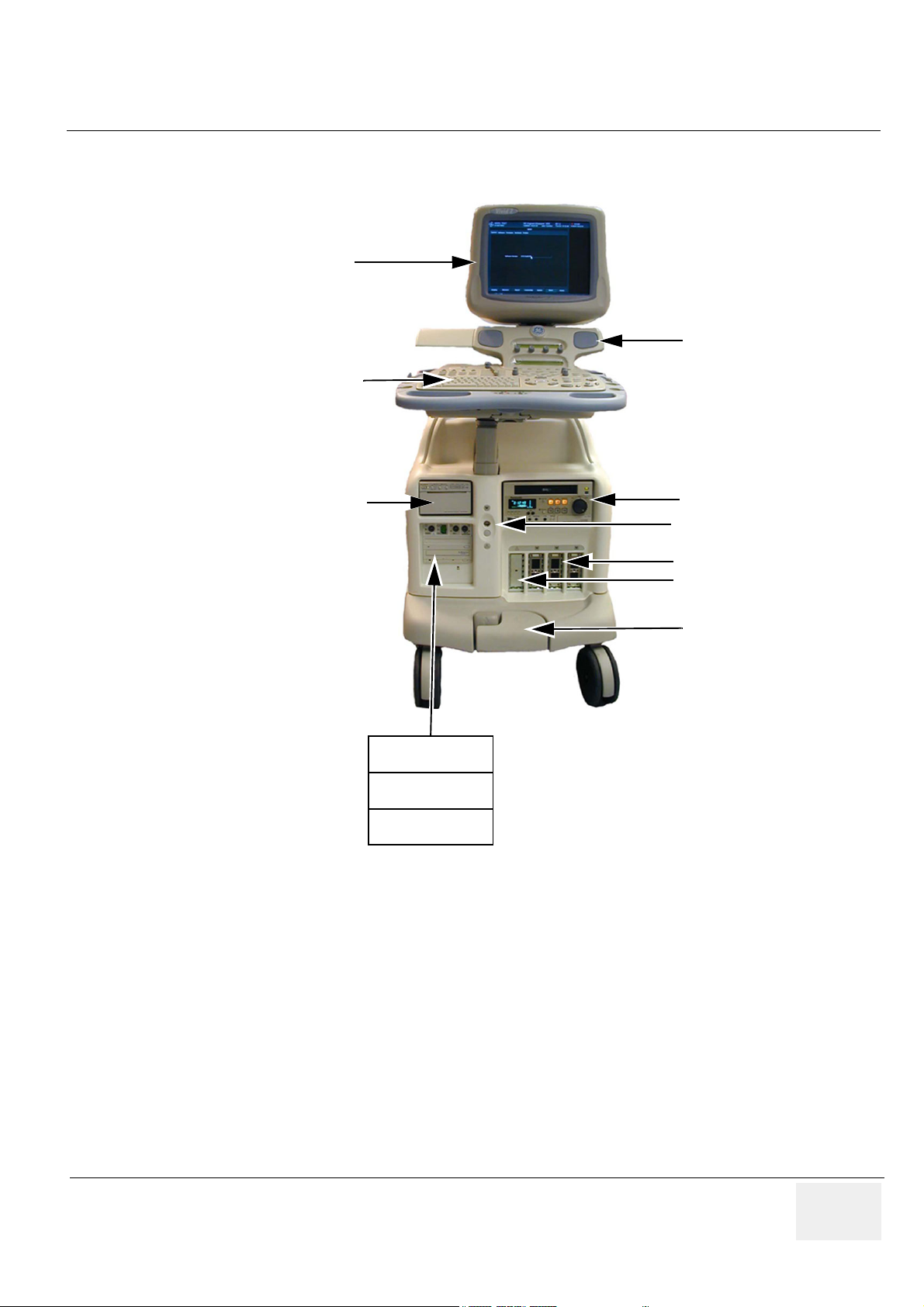
1-1-4-1 Overview (cont’d)
Monitor
Upper Panel With
Stereo Loudspeakers
Control Panel
B/w Video Printer
Figure 1-1 Vivid 7 / Vivid 7 PRO Major Components
VCR
Doppler (PEDOF) connector
Probe Connectors
Parking Slot
Brake Pedals
Patient I/O
MO Disk
CD-R Drive
Chapter 1 - Introduction 1 - 3
Page 28

GE MEDICAL SYSTEMS
DIRECTION FC091194, REVISION 02 VIVID 7 / VIVID 7 PRO SERVICE MANUAL
1-1-4-2 History - Hardware/Software Versions
Use Table 1-3 to verify the correct/needed revision on each card in the Card Rack.
Table 1-3 Required Revisions for Cards and Modules
Card Rack
BT’01
(sw. 1.0)
Func.
Part Number Name
FA200985 Motherboard - 02 - 02 - 02
FB200060 RLY-3 05 06 05 06 05 06
FB200170 TX128-2. A B A B A B
FC200022 TX128-3 - - - - 01 01
FB200831 RX128-3B 01 A 01 A,B 01 A,B
FB200158 XDBUS-2 - 02 - 02 - 02 2x used
FB200900 BF64 - B - C - C/D/E 2x used
FB200165 FEC-II - 03 - 03, 04 - 03, 04
FB200140 RFT1 F B,C F B,C F B, C, D
FB200865 SDP 01 02 01 02 01 02
FB200991 IMP-2B A A A A,B A A,B
FA200945 Power, DC - 02 - 02 - 02
FB200574 Power, TX (TXPS) - 03 - 03 - 03
Rev.
MCD
BT’01
(sw. 1.0 / 1.1 / 1.2)
Func.
Rev.
MCD
BT’02
(sw. 2.0 / 2.1)
Func.
Rev.
MCD
Comments
MCD rev. 07 includes a
noisefix for use of PAMPTE
probe.
For Vivid 7 produced before
June 3, 2002 and for Vivid 7
Replacement for FB200170
used on Vivid 7 produced after
June 3, 2002
Both MCD rev. B, C and D may
be used.
PRO
FB200724 AC Controller - 06 - 06/07 - 08
FC200079 AC Power 100-120V - 01 - 01 - 01
FC200081 AC Power 220-240V - 01 - 01 - 01
FB200198 External I/O Complete 08 08 08, 09, 10
FB200197
Internal I/O Board
Complete
05 06 05 06 05 06
08, 09, 1008, 09, 1008, 09,
1 - 4 -
Covers both 100-120 VAC and
220-240 VAC
AC Power supply for 100-120
VAC
Used as replacement for AC
Controller, FB200724 on 100120 VAC units
AC Power supply for 220-240
VAC
Used as replacement for AC
Controller, FB200724 on 220240 VAC units.
10
Page 29
GE MEDICAL SYSTEMS
DIRECTION FC091194, REVISION 02 VIVID 7 / VIVID 7 PRO SERVICE MANUAL
1-1-4-2 History - Hardware/Software Versions (cont’d)
Table 1-4 Required Revisions for Cards and Modules
Backend Rack
Part Number Name
BT’01
(sw. 1.0)
Func.
Rev.
MCD
BT’01
(sw. 1.0 / 1.1 / 1.2)
Func.
Rev.
MCD
BT’02
(sw. 2.0 / 2.1)
Func.
Rev.
MCD
Comments
BACKEND PROCESSOR Used in Production Before September 2002
FB200480 BACKEND PROCESSOR - 02 - 02 - 02
FA200801
2266548-5
PATIENT I/O MODULE II
(COMPL)
Battery For Backend
Processor UPS
-E-E-E
- N/A - N/A - N/A
MCD revision F, G, H or I may
also be used
BACKEND PROCESSOR - II Used in Production After September 2002
2348186
2348186-20 POWER SUPPLY - - - - - -
2348186-21 CD RW DRIVE - - - - - -
2348186-22 PATIENT IO MODULE - - - - - - Same as FA200801(?)
2348186-24
2348186-25 FAN - - - - - -
BACKEND
PROCESSOR-II
WITHOUT MO DRIVE
MOD DRIVE 9.0G
CAPACITY SCSI
- - - - - -
- - - - - -
Chapter 1 - Introduction 1 - 5
Page 30

GE MEDICAL SYSTEMS
DIRECTION FC091194, REVISION 02 VIVID 7 / VIVID 7 PRO SERVICE MANUAL
1-1-4-3 History - Supported Probes
Table 1-5 Supported Probes and SW Versions
PROBES
Sector
3S (Probe, Sector 3S)
3S, Comfort Scan Probe
M3s (Probe, AMA Sector M3s)
5S (Probe, Sector 5S)
7S (Probe, Sector 7S)
10S (Probe, Sector 10S)
PAMPTE
6T (Probe, TEE 6T)
8T (Probe, TEE 8T)
Linear & Convex & Others
7L (Probe, Linear 7L)
10L (Probe, Linear 10L)
12L (Probe, Linear 12L)
M12L
3.5 C (Probe, Convex 3C)
PART
SUPPORTED MODELS & SW VERSION
NUMBER
2252157 3S PROBE, L500 BT-01 SW ver. 1.x.x BT-02 SW VER. 2.x.x BT-02 SW VER. 2.x.x
2323337
2295649
2290751
2263669 7S PROBE BT-01 SW ver. 1.x.x BT-02 SW VER. 2.x.x BT-02 SW VER. 2.x.x
2298589
KN100022
KN100023
2294521 7L PROBE TYPE (EXP) BT-01 SW ver. 1.x.x BT-02 SW VER. 2.x.x BT-02 SW VER. 2.x.x
2294523
2295377
2294511 M12L MIH PROBE ----------- BT-02 SW VER. 2.x.x BT-02 SW VER. 2.x.x
2296158
NAME
3S COMFORTSCAN
PROBE
2295649 M3S AMA
SECT.
5S SECTOR
TRANSDUCER
10 S SECTOR
TRANSDUCER
KN100022 6T TEE
PROBE
KN100023 8T PED.TEE
PROBE
10L PROBE TYPE
(EXP)
12L PROBE TYPE
(EXP)
3.5C CONVEX
TRANSDUCER
BT-01, V7 BT-02, V7 BT-02, V7 PRO
BT-01 SW ver. 1.x.x BT-02 SW VER. 2.x.x BT-02 SW VER. 2.x.x
BT-01 SW ver. 1.x.x BT-02 SW VER. 2.x.x -----------
BT-01 SW ver. 1.x.x BT-02 SW VER. 2.x.x BT-02 SW VER. 2.x.x
BT-01 SW ver. 1.x.x BT-02 SW VER. 2.x.x BT-02 SW VER. 2.x.x
BT-01 SW ver. 1.x.x BT-02 SW VER. 2.x.x BT-02 SW VER. 2.x.x
BT-01 SW ver. 1.x.x BT-02 SW VER. 2.x.x BT-02 SW VER. 2.x.x
BT-01 SW ver. 1.x.x BT-02 SW VER. 2.x.x BT-02 SW VER. 2.x.x
BT-01 SW ver. 1.x.x BT-02 SW VER. 2.x.x BT-02 SW VER. 2.x.x
BT-01 SW ver. 1.x.x BT-02 SW VER. 2.x.x BT-02 SW VER. 2.x.x
5C (Probe, Convex 5C)
i13L
E8C
Pencil
P2D Pencil Probe
P6D Pencil Probe
2294516 5C PROBE TYPE (EXP) BT-01 SW ver. 1.x.x BT-02 SW VER. 2.x.x BT-02 SW VER. 2.x.x
KW100011
2294641 E8C PROBE ----------- BT-02 SW VER. 2.x.x BT-02 SW VER. 2.x.x
TE100024
TQ100002
KW011 I13L
INTRAOP.PROBE
TE100024 PENCIL
PROBE 2D
TQ100002 PENCIL
PROBE 6D
1 - 6 -
----------- BT-02 SW VER. 2.x.x BT-02 SW VER. 2.x.x
BT-01 SW ver. 1.x.x BT-02 SW VER. 2.x.x BT-02 SW VER. 2.x.x
BT-01 SW ver. 1.x.x BT-02 SW VER. 2.x.x BT-02 SW VER. 2.x.x
Page 31

GE MEDICAL SYSTEMS
DIRECTION FC091194, REVISION 02 VIVID 7 / VIVID 7 PRO SERVICE MANUAL
1-1-4-4 How to Turn the Scanner ON and OFF
Please refer to Chapter 4, section 4-2-1 - Power ON/ Boot Up, for a detailed description of how to turn
the scanner ON and to Chapter 4, section 4-2-2 - Power Shut Down for a detailed description of how to
turn the scanner OFF.
1-1-4-5 How to Check for Hardware/Software Version, Installed Options
• Please refer to "History - Hardware/Software Versions" on page 1-4 to check the hardware versions
on the boards
• Please refer to "Software Configuration Checks" on page 4-63 to check the software versions on
local software on the boards.
• Please refer to "Functional Checks" on page 4-14 to check for installed options.
1-1-5 Purpose of Operator Manual(s)
The Operator Manual(s) should be fully read and understood before operating the Vivid 7 / Vivid 7 PRO
and also kept near the unit for quick reference.
Chapter 1 - Introduction 1 - 7
Page 32

GE MEDICAL SYSTEMS
DIRECTION FC091194, REVISION 02 VIVID 7 / VIVID 7 PRO SERVICE MANUAL
Section 1-2
Important Conventions
1-2-1 Conventions Used in Book
1-2-1-1 Model Designations.
This manual covers the Vivid 7 / Vivid 7 PRO scanners listed in Ta b le 1 -2 .
1-2-1-2 Icons.
Pictures, or icons, are used wherever they will reinforce the printed message. The icons, labels and
conventions used on the product and in the service information are described in this chapter.
1-2-1-3 Safety Precaution Messages.
Various levels of safety precaution messages may be found on the equipment and in the service
information. The different levels of concern are identified by a flag word that precedes the precautionary
message. Known or potential hazards are labeled in one of three ways:
DANGER
Danger is used to indicate the presence of a hazard that will cause severe
personal injury or death if the instructions are ignored.
WARNINGWARNING
CAUTION
NOTICE
NOTE: Notes are used to provide important information about an item or a procedure.
Warning is used to indicate the presence of a hazard that can cause severe personal
injury and property damage if instructions are ignored.
Caution is used to indicate the presence of a hazard that will or can cause minor personal injury
and property damage if instructions are ignored. Equipment Damage Possible.
Notice is used when a hazard is present that can cause property damage but has absolutely no
personal injury risk.
Example: Disk drive will crash.
Be sure to read the notes; the information contained in a note can often save you time or effort.
1 - 8 Section 1-2 - Important Conventions
Page 33

GE MEDICAL SYSTEMS
DIRECTION FC091194, REVISION 02 VIVID 7 / VIVID 7 PRO SERVICE MANUAL
1-2-2 Standard Hazard Icons
Important information will always be preceded by the exclamation point contained within a
triangle, as seen throughout this chapter. In addition to text, several different graphical icons (symbols)
may be used to make you aware of specific types of hazards that could possibly cause harm.
Table 1-6 Standard Hazard Icons
ELECTRICAL MECHANICAL RADIATION
LASER HEAT PINCH
LASER
LIGHT
Some others make you aware of specific procedures that should be followed.
Table 1-7 Standard Icons that indicates that a special procedure is to be used
AVOID STATIC ELECTRICITY TAG AND LOCK OUT WEAR EYE PROTECTION
TAG
&
LOCKOUT
Date
Signed
Chapter 1 - Introduction 1 - 9
Page 34

GE MEDICAL SYSTEMS
DIRECTION FC091194, REVISION 02 VIVID 7 / VIVID 7 PRO SERVICE MANUAL
1-2-3 Product Icons
The following table describes the purpose and location of safety labels and other important information
provided on the equipment.
Table 1-8 Product Icons
LABEL/SYMBOL PURPOSE/MEANING LOCATION
Manufacturer's name and address
Identification and Rating Plate
Date of manufacture
Model and serial numbers
Electrical ratings
Rear of console near power inlet
Type/Class Label
IP Code (IPX8/IP68)
Device Listing/Certification Labels
CAUTION - This unit weighs...Special
care must be used to avoid..."
Used to indicate the degree of safety or
protection.
Indicates the degree of protection
provided by the enclosure per IEC 529.
IPX8 indicates drip proof and may be
used in an Operating Theater.
The footswitch delivered with Vivid 7 /
Vivid 7 PRO is IP68 rated.
Equipment Type BF (man in the box
symbol) IEC 878-02-03 indicates B
Type equipment having a floating
applied part.
Equipment Type CF (heart in the box
symbol) IEC 878-02-05 indicates
equipment having a floating applied part
having a degree of protection suitable
for direct cardiac contact.
Laboratory logo or labels denoting
conformance with industry safety
standards such as UL or IEC.
This precaution is intended to prevent
injury that may result if one person
attempt to move the unit considerable
distances or on an incline due to the
weight of the unit.
Footswitch
Probe connectors including Doppler
probe connector
ECG connector and surgical probes
Rear of console
On the console where easily seen
during transport
"DANGER - Risk of explosion used in..."
The system is not designed for use with
flammable anesthetic gases.
“CAUTION” The equilateral triangle is
usually used in combination with other
symbols to advise or warn the user.
1 - 10 Section 1-2 - Important Conventions
Rear of console
Various
Page 35

GE MEDICAL SYSTEMS
DIRECTION FC091194, REVISION 02 VIVID 7 / VIVID 7 PRO SERVICE MANUAL
Table 1-8 Product Icons (continued)
LABEL/SYMBOL PURPOSE/MEANING LOCATION
“ATTENTION - Consult accompanying
documents” is intended to alert the user
to refer to the operator manual or other
instructions when complete information
cannot be provided on the label.
“CAUTION - Dangerous voltage” (the
lightning flash with arrowhead in
equilateral triangle) is used to indicate
electric shock hazards.
Various
Various
“Mains OFF” Indicates the power off
position of the mains power switch.
“OFF/Standby” Indicates the power off/
standby position of the power switch.
CAUTION
This Power Switch DOES NOT
ISOLATE Mains Supply
“Mains ON” Indicates the Power ON
position of the mains power switch.
“ON” Indicates the power on position of
the power switch.
CAUTION
The Power Switch on the Front Panel
DOES NOT ISOLATE Mains Supply
“Protective Earth” Indicates the
protective earth (grounding) terminal.
“Equipotentiality” Indicates the terminal
to be used for connecting equipotential
conductors when interconnecting
(grounding) with other equipment.
Rear of system adjacent to mains switch
Adjacent to On/Off (Standby) Switch
Used several places inside the scanner.
Rear of console
Chapter 1 - Introduction 1 - 11
Page 36

GE MEDICAL SYSTEMS
DIRECTION FC091194, REVISION 02 VIVID 7 / VIVID 7 PRO SERVICE MANUAL
Section 1-3
Safety Considerations
1-3-1 Introduction
The following safety precautions must be observed during all phases of operation, service and repair of
this equipment. Failure to comply with these precautions or with specific warnings elsewhere in this
manual, violates safety standards of design, manufacture and intended use of the equipment.
1-3-2 Human Safety
Operating personnel must not remove the system covers.
Servicing should be performed by authorized personnel only.
Only personnel who have participated in a Vivid 7 / Vivid 7 PRO Training Seminar are authorized to
service the equipment.
1-3-3 Mechanical Safety
WARNINGWARNING
WARNINGWARNING
WARNINGWARNING
CAUTION
CAUTION
CAUTION
WHEN THE UNIT IS RAISED FOR A REPAIR OR MOVED ALONG ANY INCLINE, USE
EXTREME CAUTION SINCE IT MAY BECOME UNSTABLE AND TIP OVER.
ULTRASOUND PROBES ARE HIGHLY SENSITIVE MEDICAL INSTRUMENTS THAT CAN
EASILY BE DAMAGED BY IMPROPER HANDLING. USE CARE WHEN HANDLING AND
PROTECT FROM DAMAGE WHEN NOT IN USE. DO NOT USE A DAMAGED OR
DEFECTIVE PROBE. FAILURE TO FOLLOW THESE PRECAUTIONS CAN RESULT IN
SERIOUS INJURY AND EQUIPMENT DAMAGE.
NEVER USE A PROBE THAT HAS FALLEN TO THE FLOOR. EVEN IF IT LOOKS OK, IT
MAY BE DAMAGED.
Ensure that nobody touch the console arm/frogleg when moving the keyboard console.
Do not move the unit if the keyboard console is in unlocked position.
Always lock the Control Console in its parking (locked) position before moving the scanner
around.
WARNINGWARNING
WHEN THE TOP CONSOLE IS IN ITS LOCKED POSITION, THE GAS SPRING IS
COMPRESSED AND STORES MECHANICAL ENERGY. DURING NORMAL OPERATION
THE TOP CONSOLE, THE WEIGHT OF THE MONITOR AND THE MECHANICAL FORCE
OF THE GAS SPRING ARE IN BALANCE. TAKE CARE IF/WHEN YOU ACTIVATE THIS
GAS SPRING. PERSONAL INJURY CAN OCCUR AFTER THE PANEL IS REMOVED AND
THE SPRING PRESSURE IS RELEASED. TAKE CARE WHEN YOU REPAIR THE
ELEVATION ASSEMBLY.
1 - 12 Section 1-3 - Safety Considerations
Page 37

GE MEDICAL SYSTEMS
DIRECTION FC091194, REVISION 02 VIVID 7 / VIVID 7 PRO SERVICE MANUAL
1-3-3 Mechanical Safety (cont’d)
CAUTION
VIVID 7 / VIVID 7 PRO weighs 190 kg (419 lbs) or more, depending on installed peripherals, when
ready for use. Care must be used when moving it or replacing its parts. Failure to follow the
precautions listed below could result in injury, uncontrolled motion and costly damage.
CAUTION
-
Do not transport Vivid 7 / Vivid 7 PRO in a vehicle without locking the casters (wheels).
ALWAYS:
- Be sure the pathway is clear.
- Use slow, careful motions.
- Use two people when moving on inclines or lifting more than 23 kg (50 lbs).
NOTE: Special care should be taken when transporting the unit in a vehicle:
• Lock keyboard in place.
• Eject Magneto Optical disk from the MO Drive (if installed).
• Eject CD from CD drive.
• Secure the unit in an upright position.
• Lock the casters (wheels) (brake)
• DO NOT use the Control Panel as an anchor point.
• Place the probes in their carrying case.
CAUTION
Keep the heat venting holes on the monitor unobstructed to avoid overheating of the monitor.
1-3-4 Electrical Safety
1-3-4-1 Safe Practices
Follow these guidelines to minimize shock hazards whenever you are using the scanner;
• The equipment chassis must be connected to an electrical ground.
• The unit is equipped with a three-conductor AC power cable. This must be plugged into an approved
electrical outlet with safety ground.
• The power outlet used for this equipment should not be shared with other types of equipment.
• Both the system power cable and the power connector must meet international electrical standards.
1-3-4-2 Probes
Follow these guidelines before connecting a probe to the scanner;
• Inspect the probe prior to each use for damage or degradation to the;
- housing
- cable strain relief
-lens
- seal
• Do not use a damaged or defective probe.
Chapter 1 - Introduction 1 - 13
Page 38

GE MEDICAL SYSTEMS
DIRECTION FC091194, REVISION 02 VIVID 7 / VIVID 7 PRO SERVICE MANUAL
• Never immerse the probe connector or adapter into any liquid.
1-3-5 Labels Locations
1-3-5-1 Labels on Front of Monitor and Control Panel
Table 1-9 Labels on Front of Monitor and Control Panel
DESCRIPTION ILLUSTRATION
Label, Vivid 7 (Monitor) - BT’01
Label, Vivid 7 (Monitor) - BT’02
Label, Vivid 7 PRO (Monitor) - BT’02
Label, GE Logo
1 - 14 Section 1-3 - Safety Considerations
Page 39

GE MEDICAL SYSTEMS
DIRECTION FC091194, REVISION 02 VIVID 7 / VIVID 7 PRO SERVICE MANUAL
Table 1-9 Labels on Front of Monitor and Control Panel (continued)
DESCRIPTION ILLUSTRATION
Label, On/Off Switch
(Two versions of the label have been
used, the one to the right is the latest
version.)
OR
ON/OFF:
press once
FC314104 03
Label position
Chapter 1 - Introduction 1 - 15
Page 40

GE MEDICAL SYSTEMS
DIRECTION FC091194, REVISION 02 VIVID 7 / VIVID 7 PRO SERVICE MANUAL
1-3-5-2 Labels on Front Handle
Table 1-10 Labels on Front Handle
DESCRIPTION ILLUSTRATION
Label, Front Handle
(Three versions of the label have been
used.
The lower one is the latest version)
OR
OR
OR
1 - 16 Section 1-3 - Safety Considerations
Page 41

GE MEDICAL SYSTEMS
DIRECTION FC091194, REVISION 02 VIVID 7 / VIVID 7 PRO SERVICE MANUAL
1-3-5-3 Labels Near Connectors on Front
Table 1-11 Labels Near Connectors on Front
DESCRIPTION ILLUSTRATION
Label, Probe Connector
(The Label, “Probe Connector” consists
of three labels, named;
- “Main Label Part”,
- “Heart Symbol” and
- “See Manual symbol”.)
Label, Patient I/O Module II
Label CD ROM
(introduced April 2002)
Chapter 1 - Introduction 1 - 17
Page 42

GE MEDICAL SYSTEMS
DIRECTION FC091194, REVISION 02 VIVID 7 / VIVID 7 PRO SERVICE MANUAL
1-3-5-4 Label on External I/O
Table 1-12 Label, External I/O
DESCRIPTION ILLUSTRATION
Label, External. I/O
1 - 18 Section 1-3 - Safety Considerations
Page 43

GE MEDICAL SYSTEMS
DIRECTION FC091194, REVISION 02 VIVID 7 / VIVID 7 PRO SERVICE MANUAL
1-3-5-5 Labels at AC Mains Inlet and Circuit Breaker
Table 1-13 Labels at AC Mains Inlet and Circuit Breaker (used before May 2002)
DESCRIPTION ILLUSTRATION
Label, Warning
System: P/N, Pwr.rating
Label,
Label, System: S/N
or
Ground (GND) Label. (Used on 230 VAC Systems and some 100-120 VAC Systems.) l
or
Label, GND-symbol
Chapter 1 - Introduction 1 - 19
Page 44

GE MEDICAL SYSTEMS
DIRECTION FC091194, REVISION 02 VIVID 7 / VIVID 7 PRO SERVICE MANUAL
Table 1-13 Labels at AC Mains Inlet and Circuit Breaker (used before May 2002) (continued)
DESCRIPTION ILLUSTRATION
l
Hospital Grade Ground
Label, GND-symbol., Hospital Grade
(GND) Label. (Used on some
100-120 VAC Systems)
Table 1-14 Labels at AC Mains Inlet and Circuit Breaker (used after May 2002)
DESCRIPTION ILLUSTRATION
Label, AC Controller
1 - 20 Section 1-3 - Safety Considerations
Page 45

GE MEDICAL SYSTEMS
DIRECTION FC091194, REVISION 02 VIVID 7 / VIVID 7 PRO SERVICE MANUAL
1-3-5-6 Label on Rear Cover
Table 1-15 Label on Rear Cover
DESCRIPTION ILLUSTRATION
l
Label, General Info
(Located on rear of system)
Label used for Vivid 7 before 2 May 2002
Label, General Info
(Located on rear of system)
Label used for Vivid 7 after 2 May 2002
Chapter 1 - Introduction 1 - 21
Page 46

GE MEDICAL SYSTEMS
DIRECTION FC091194, REVISION 02 VIVID 7 / VIVID 7 PRO SERVICE MANUAL
Table 1-15 Label on Rear Cover (continued)
DESCRIPTION ILLUSTRATION
Label, General Info
(Located on rear of system)
Label used for Vivid 7 to China
Label, General Info
(Located on rear of system)
Label used for Vivid 7 PRO
1 - 22 Section 1-3 - Safety Considerations
Page 47

GE MEDICAL SYSTEMS
DIRECTION FC091194, REVISION 02 VIVID 7 / VIVID 7 PRO SERVICE MANUAL
Table 1-15 Label on Rear Cover (continued)
DESCRIPTION ILLUSTRATION
Label, General Info
(Located on rear of system)
Label used for Vivid 7 PRO to China
Chapter 1 - Introduction 1 - 23
Page 48

GE MEDICAL SYSTEMS
DIRECTION FC091194, REVISION 02 VIVID 7 / VIVID 7 PRO SERVICE MANUAL
1-3-5-7 Labels on Internal I/O (Inside Scanner)
Label on Front End Card Cage Side of Internal I/O
Figure 1-2 Labels on Internal I/O (Inside Scanner), Front End Card Cage Side of Internal I/O
1 - 24 Section 1-3 - Safety Considerations
Page 49

GE MEDICAL SYSTEMS
DIRECTION FC091194, REVISION 02 VIVID 7 / VIVID 7 PRO SERVICE MANUAL
1-3-5-8 Labels on Internal I/O (Inside Scanner)
Label on Backend Processor Side of Internal I/O
Figure 1-3 Labels on Internal I/O (Inside Scanner), Backend Processor Side of Internal I/O
Chapter 1 - Introduction 1 - 25
Page 50

GE MEDICAL SYSTEMS
Rack
V
4
n
DIRECTION FC091194, REVISION 02 VIVID 7 / VIVID 7 PRO SERVICE MANUAL
1-3-5-9 Label, Internal Connections (Int.Conn.) - Part 1, Left Part of Label
Located on the outside of the Front End Card Rack’s cover (inside unit).Different versions of the label
has been used since production start. The label shown here, is the latest version.
AC
Cable and Connector num bering and nam ing system u sed:
IIO= Internal IO m odule
EIO= External IO m odule
BEP = B acken d Processor
FEP = Frontend P rocessor
ACP = AC contro ller m o dule
ACD = AC distribution box
ACT = AC iso lation transform er m odule
BEPIO= IO m odule on the BEP
A xx : connectors on IIO with other connections than the BEP
B xx : connectors on IIO that are connected to BEP
C xx : connectors on BEP, except for the BEPIO
D xx : connectors on BEPIO
E xx : connector on the BEP pow er supply
Fxx : connectors on ACP
G xx : connectors on FEP
H xx :external accesable connectors (D oppler probe)
K xx : connectors on MODEM
M xx : connectors on ACT
N xx : connectors on ACD
Lxx : connectors on EIO
connector
to EIO
25
P31
A13
A12
F
F
81
159
M
113
915
81
M
18
69
159
C onnector to
motherboard
1425
P30
A12 S pare pow er (future option)
A13 P ow er to 3D box (future option)
A14 AC pow er control
A15 Signals to rotation adapter (future option)
A16 Signals to 3D box (future option)
M
15
F
A
1
Distribution
box
N5
N4
N3
N2
N1
Monitor
Peripherals
F1 F2 F3 F4
115 V
115 V
or
230 V
230 V
B ack End
M odem
Processor
F5
230
230 V
F6
From Iso lation
transformer
H1
DC-power
BF-64
BF-64
RX-128
TX-128
Relay board
FEC -2
IMP
RFT-1
SDP-2
Not used
G3
G2
G1
TX-pow er
Board location in Front E nd Processor (FEP)
Front End
supply
supply
G
P32
A15
A14
IIO seen from F
EP side
A16
L4: A ud io out (right)
L5: A udio out (left)
L6: T rig out
L7: F oot sw itch
L8: S erial port
L9: R e m ote expose #1
L10: R em ote expose #2
L11: A nalog modem
L12: C om posite video outp u t
L13: B & W video output
L14: S -Video output
L15: S V G A output
L16: U SB
L17: E thernet
L1 L2
Service
use ONLY
(rem ote
pow er on/off
control)
69
M
15
External IO m odule
Figure 1-4 Label, Internal Connections - Part 1, Left Part of Label
1 - 26 Section 1-3 - Safety Considerations
RS-232
C onnect
to InS ite
MODEM
69
M
15
L3
14
Analog ue
phone
C onnect
to InS ite
MODEM
L4 L5
L1 1 L1 2 L13 L14
L6
External
(F ro
L7
Page 51

GE MEDICAL SYSTEMS
e
TX
128
DIRECTION FC091194, REVISION 02 VIVID 7 / VIVID 7 PRO SERVICE MANUAL
1-3-5-10 Label, Internal Connections (Int.Conn.) - Part 2, Right Part of Label
Located on the outside of the Front End Card Rack’s cover (inside unit). Different versions of the label
has been used since production start. The label shown here, is the latest version.
rol
Fan
cont
F9
230 V
115 V
Voltage Selection
on Peripherals
69
15
M
F8
Monitor
Peripherals
M odem
F1 F2 F3 F4
115 V
115 V
or
230 V
230 V
F6
From Iso lation
transformer
230 V
W ARNING !
Live Voltage inside,
B ack End
Processor
Front End
Rack
F5
230 V
do not o p en.
AC pow er control m odule
115V or 230V inlet
voltage selection
230 V
F7
115 V
To Isolation
transformer
115V = 100-
230V = 220-
(½ or 2 times in
voltag
120V
240V
let
e)
supply
BF-64
BF-64
RFT-1
FEC -2
RX-128
SDP-2
ard location in Front E nd Processor (FEP)
L4 L5
L1 1 L1 2 L13 L14
IMP
G2
L6
DC-power
RESET
M
C able to
C15
transformer
L8
L1 5
Iso lation
m odule
F
Cutout in the label
60,0
M1
L9
L1 0
M odem
pow er
K4
L1 6
L1 7
supply
K3
M odem
M T5634Z BA
K1 K2
Not used
G3
supply
TX-pow er
G4
L7
External IO m odule
ue
e
ct
ite
M
(Front view)
Part no. : FB 31474 6
Rev. : 05
Figure 1-5 Label, Internal Connections - Part 1, Right Part of Label
Chapter 1 - Introduction 1 - 27
Page 52

GE MEDICAL SYSTEMS
DIRECTION FC091194, REVISION 02 VIVID 7 / VIVID 7 PRO SERVICE MANUAL
1-3-5-11 Label, Internal Connections (Int.Conn.) - Upper Part
Located on the outside of the Backend Processor’s Cover (inside unit)
Figure 1-6 Label, Internal Connections (Int.Conn.), Upper Part
1 - 28 Section 1-3 - Safety Considerations
Page 53

GE MEDICAL SYSTEMS
DIRECTION FC091194, REVISION 02 VIVID 7 / VIVID 7 PRO SERVICE MANUAL
1-3-5-12 Label, Internal Connections (Int.Conn.) - Lower Part
Located on the outside of the Backend Processor’s Cover (inside unit)
Figure 1-7 Label, Internal Connections (Int.Conn.) - Lower Part
Chapter 1 - Introduction 1 - 29
Page 54

GE MEDICAL SYSTEMS
DIRECTION FC091194, REVISION 02 VIVID 7 / VIVID 7 PRO SERVICE MANUAL
1-3-5-13 Label, Internal Connections (Int.Conn.) - Upper Part
Located on the outside of the Backend Processor’s Cover (inside unit)
Connector to motherboard
de
i
om
r
s
f
)
n
P
e
E
se
B
(
e
r
l
u
so
d
s
o
m
ce
o
r
O
P
lI
a
d
n
n
r
E
e
t
n
i
ck
a
B
915
M
A5
18
15 9
F
A4
81
69
A3
5
M
1
P31
B3
B8
B7
B1 B2
Connectors to/from Back End
A11
A10
F
F
69
1
69
1
6
1
M
M
9
5
5
5
1425
1
26
125
F
50
B4
13
5
69
1
B6
B5
P32
M
B9
B1 USB#1 (top console conection)
B2 USB#2 (external i/o connection)
B3 10/100 Base-TX Ethernet
B4 Audio in to BEP, Audio out from BEP, Microphone in to BEP
B5 PC2IO board signals
B6 PC2IO board signals and power
B7 COM (external i/o connection - setup as COM1)
B8 COM (modem - setup as COM2)
B9 BEP Power Supply control (UPS)
69
5
610
F
51
A2
M
1
15 11
A1
A7
A6
A9
A8
+12V
+5V
+15V
+10V
+6V
+5V
+3.3V
End
Back
From
-15V
-5V
Figure 1-8 Label, Internal Connections (Int.Conn.), Upper Part
1 - 30 Section 1-3 - Safety Considerations
A1 BW printer video, printer remote control
A2 VCR remote control (RS232)
A3 Spare RS232
A4 Signals & power to/from top console
A5 Signals to/from top console
A6 Audio left out to VCR
A7 Audio right out to VCR
A8 Audio left reply from VCR
A9 Audio right reply from VCR
A10 SVideo out to VCR
A11 SVideo in from VCR
Page 55

GE MEDICAL SYSTEMS
e
DIRECTION FC091194, REVISION 02 VIVID 7 / VIVID 7 PRO SERVICE MANUAL
1-3-5-14 Label, Internal Connections (Int.Conn.) - Lower Part
Located on the outside of the Backend Processor’s Cover (inside unit)
Not used
Connector to moth
PCI Bridge
1
6
to B9
UPS Control
Not used
Not used
Not used
Audio Out
C17
F
1
to Front End Rack
LAN
68
C12
50
C10
Audio In
to B3
1425
No external connection
USB #3 to B7
C13C6
F
P32
81
F
Power for i/o boards - to B6
69
1
69
1
6
1
M
M
9
5
5
5
1425
F
50
25
B4
13
5
69
M
1
B6
B5
B9
B1 USB#1 (top console conection)
B2 USB#2 (external i/o connection)
B3 10/100 Base-TX Ethernet
B4 Audio in to BEP, Audio out from BEP, Microphone in to BEP
B5 PC2IO board signals
B6 PC2IO board signals and power
B7 COM (external i/o connection - setup as COM1)
B8 COM (modem - setup as COM2)
B9 BEP Power Supply control (UPS)
F
125
125
Signals to i/o boards - to B5
610
15 11
15 11
15 11
15 11
SVGA in - from C13 SVGA to monitor RGB to Color Printer
D5
51
F
F
610
610
D4
51
51
F
610
D3
51
BEP
FAN
D2
15 9
26
26
D1
50
50
+12V
+5V
+15V
End
Back
From
-15V
35
134
5
F
9
26
F
125
14
USB #6USB #5
C21
14
to Color Printer to BW Printer
C20
C15 C16
SCSI for optional MO drive
Mic
C9
C11
14
14
C18
C19
F
610
51
15 11
to B4
USB #4 NOT
VIDEO to D3
PCI
slot 6
PCI
slot 5
PCI
slot 4
PCI
slot 3
PCI
slot 2
PCI
slot 1
slot
AGP
USED
+10V
-5V
+6V
+5V
+3.3V
A1 BW printer video, printer remote control
A2 VCR remote control (RS232)
A3 Spare RS232
A4 Signals & power to/from top console
A5 Signals to/from top console
A6 Audio left out to VCR
A7 Audio right out to VCR
A8 Audio left reply from VCR
A9 Audio right reply from VCR
A10 SVideo out to VCR
A11 SVideo in from VCR
BEP power supply
E1
M
230V
Voltage
Selection
SHALL be
AC Power
Connect to AC
Control Module
NOT USED
Parallel Port
13
5
1
M
69
COM to B8
C5
C4
C3
14
14
USB #1 to B1
USB #2 to B2
NOT
USED
C1
C2
Mouse
Keyboard
NOT USED
Figure 1-9 Label, Internal Connections (Int.Conn.) - Lower Part
Chapter 1 - Introduction 1 - 31
Page 56

GE MEDICAL SYSTEMS
DIRECTION FC091194, REVISION 02 VIVID 7 / VIVID 7 PRO SERVICE MANUAL
1-3-5-15 Label, Disassembly Nester, Part 1 (Left Part of Label)
Located on the outside of the Front End Card Rack’s Cover (inside unit)
DISASSEMBLY INSTRUCTIONS
Remove all screws on rear side of monitor cover, and remove cover.
Remove all screws on rear side of monitor front cover, and remove front cover.
Remove all screws on the cover located under the shelf underneath the monitor, and remove cover.
Detach monitor by removing four unbrako screws located underneath the monitor neck.
Remove shelf by loosening all screws underneath it and remove speakers from shelf.
Remove all screws underneath operators panel. Disconnect and remove alphanumeric keyboard and
operators panel.
Remove probe holders and front handle.
Remove all unbrako screws, which fasten the top console cable to the console and loosen the cable.
Remove top console and horizontal movement mechanism by unscrewing the big unbrako screw on
top of the rear base of the horizontal movement mechanism.
Remove all quarterturn screws on both sidepanels of the system. Side panels can now be removed.
Remove screws underneath the pedals to remove the pedal plastics.
Remove the footrest bumper by unscrewing four screws.
Remove all screws on the rear-, top- and front covers to loosen the covers.
Remove rear handle by unscrewing all screws.
Remove fan cover by removing all fastening screws.
Remove fan bracket w/fan by removing all fastening screws.
Remove all peripheral units.
Disconnect, then remove all cables.
Detach computer by unscrewing all fastening screws.
Remove external i/o box by unscrewing all fastening screws.
Remove internal i/o box by unscrewing all fastening screws.
Remove ac-power box by unscrewing all fastening screws.
Remove ac-transformer box by unscrewing all fastening screws.
Remove sheet metal cover on electronic rack on lower right side.
Remove all PCB’s from the electronic rack.
Remove the two power supplys from the electronic rack by unscrewing all fastening screws.
Unscrew two screws on the connector (front) panel of the electronic rack, and remove the panel.
Remove the electronic cabinet by unscrewing all fastening screws in front of it and behind of it.
Remove the pedal mechanism by unscrewing all fastening screws.
Remove the wheels by unscrewing all fastening screws.
Figure 1-10 Label, Disassembly Instruction, Part 1 (Left Part of Label)
1 - 32 Section 1-3 - Safety Considerations
Page 57

GE MEDICAL SYSTEMS
DIRECTION FC091194, REVISION 02 VIVID 7 / VIVID 7 PRO SERVICE MANUAL
1-3-5-16 Label, Disassembly Nester, Part 2 (Right Part of Label)
Located on the outside of the Front End Card Rack’s Cover (inside unit)
PARTS DESCRIPTION DISPOSITION
Painted sheet metal, aluzinc steel Recyclable metal after cleaning
Sheet metal, aluzinc Recyclable metal
Printed circuit boards Recycling
Cables Recyclable metal. All cables are UL
listed.
Nuts, steel + nylock Recyclable metal after cleaning
Nuts, steel Recyclable metal
Screws, steel + painted Recyclable metal after cleaning
Screws, steel Recyclable metal
Casters w/rubber Recyclable metal and plastics
Beryllium copper Recyclable metal
Lithium battery To be handled by battery recycler
Covers, made from ABS plastic To be handled by plastics recycler
Bumpers, made from EPP
(expanding polypropylen)
Shelf made from Polyuretan, liquid
painted
Foot pedal, plastics made from EPP
(expanding polypropylen)
Peripheral units Follow disassembly/recycling instructions
Computer Follow disassembly/recycling instructions
Ferrite cores Reusable
Electric fans Reusable
To be handled by plastics recycler
To be handled by plastics recycler
To be handled by plastics recycler
from original manufacturer
from original manufacturer
Figure 1-11 Label, Disassembly Instruction, Part 2 (Right Part of Label)
Chapter 1 - Introduction 1 - 33
Page 58

GE MEDICAL SYSTEMS
DIRECTION FC091194, REVISION 02 VIVID 7 / VIVID 7 PRO SERVICE MANUAL
1-3-5-17 Labels on Footswitch
Table 1-16 Labels on Footswitch
DESCRIPTION ILLUSTRATION
or
Label, Footswitch
Footswitch, underneath
1 - 34 Section 1-3 - Safety Considerations
Page 59

GE MEDICAL SYSTEMS
DIRECTION FC091194, REVISION 02 VIVID 7 / VIVID 7 PRO SERVICE MANUAL
Table 1-16 Labels on Footswitch (continued)
DESCRIPTION ILLUSTRATION
LABEL, GE VINGMED
or
LABEL, GE MEDICAL SYSTEMS
Chapter 1 - Introduction 1 - 35
Page 60

GE MEDICAL SYSTEMS
DIRECTION FC091194, REVISION 02 VIVID 7 / VIVID 7 PRO SERVICE MANUAL
1-3-6 Dangerous Procedure Warnings
Warnings, such as the example below, precede potentially dangerous procedures throughout this
manual. Instructions contained in the warnings must be followed.
DANGER
DANGEROUS VOLTAGES, CAPABLE OF CAUSING DEATH, ARE PRESENT IN
THIS EQUIPMENT. USE EXTREME CAUTION WHEN HANDLING, TESTING AND
ADJUSTING.
WARNINGWARNING
WARNINGWARNING
EXPLOSION WARNING
DO NOT OPERATE THE EQUIPMENT IN AN EXPLOSIVE ATMOSPHERE. OPERATION
OF ANY ELECTRICAL EQUIPMENT IN SUCH AN ENVIRONMENT CONSTITUTES A
DEFINITE SAFETY HAZARD.
DO NOT SUBSTITUTE PARTS OR MODIFY EQUIPMENT.
BECAUSE OF THE DANGER OF INTRODUCING ADDITIONAL HAZARDS, DO NOT
INSTALL SUBSTITUTE PARTS OR PERFORM ANY UNAUTHORIZED MODIFICATION
OF THE EQUIPMENT.
1-3-7 Lockout/Tagout Requirements (For USA Only)
Follow OSHA Lockout/Tagout requirements by ensuring you are in total control of the AC power plug at
all times during the service process.
1 - 36 Section 1-3 - Safety Considerations
Page 61

GE MEDICAL SYSTEMS
DIRECTION FC091194, REVISION 02 VIVID 7 / VIVID 7 PRO SERVICE MANUAL
Section 1-4
EMC, EMI, and ESD
1-4-1 Electromagnetic Compatibility (EMC) and Interference (EMI)
Electromagnetic compatibility describes a level of performance of a device within its electromagnetic
environment. This environment consists of the device itself and its surroundings including other
equipment, power sources and persons with which the device must interface. Inadequate compatibility
results when a susceptible device fails to perform as intended due interference from its environment or
when the device produces unacceptable levels of emission to its environment. This interference is often
referred to as radio–frequency or electromagnetic interference (RFI/EMI) and can be radiated through
space or conducted over interconnecting power of signal cables. In addition to electromagnetic energy,
EMC also includes possible effects from electrical fields, magnetic fields, electrostatic discharge and
disturbances in the electrical power supply.
1-4-2 CE Compliance
Vivid 7 / Vivid 7 PRO conforms to all applicable conducted and radiated emission limits and to immunity
from electrostatic discharge, radiated and conducted RF fields, magnetic fields and power line transient
requirements.
Applicable standards are: 47CFR Part 18, IEC 601–1–2, and 806–13.
NOTE: For CE Compliance, it is critical that all covers, screws, shielding, gaskets, mesh, clamps, are
in good condition, installed tightly without skew or stress. Proper installation following all
comments noted in this service manual is required in order to achieve full EMC performance.
1-4-3 Electrostatic Discharge (ESD) Prevention
WARNINGWARNING
2.)
DO NOT TOUCH ANY BOARDS WITH INTEGRATED CIRCUITS PRIOR TO TAKING THE
NECESSARY ESD PRECAUTIONS:
1. ALWAYS CONNECT YOURSELF, VIA AN ARM-WRIST STRAP, TO THE ADVISED ESD
CONNECTION POINT LOCATED ON THE REAR OF THE SCANNER (TO THE RIGHT OF
THE POWER CONNECTOR).
2. FOLLOW GENERAL GUIDELINES FOR HANDLING OF ELECTROSTATIC SENSITIVE
EQUIPMENT.
Chapter 1 - Introduction 1 - 37
Page 62

GE MEDICAL SYSTEMS
DIRECTION FC091194, REVISION 02 VIVID 7 / VIVID 7 PRO SERVICE MANUAL
Section 1-5
Customer Assistance
1-5-1 Contact Information
If this equipment does not work as indicated in this service manual or in the User Manual, or if you
require additional assistance, please contact the local distributor or appropriate support resource, as
listed below.
Prepare the following information before you call:
- System ID serial number, --see label on rear side of unit.
- Software version.
Table 1-17 Phone Numbers for Customer Assistance
Location Phone Number
USA/ Canada
GE Medical Systems
Ultrasound Service Engineering
4855 W. Electric Avenue
Milwaukee, WI 53219
Customer Answer Center
Latin America
GE Medical Systems
Ultrasound Service Engineering
4855 W. Electric Avenue
Milwaukee, WI 53219
Customer Answer Center
Europe
GE Ultraschall Deutschland GmbH& Co. KG
BeethovenstraBe 239
Postfach 11 05 60, D-42655 Solingen
Germany
Asia (Singapore)
GE Ultrasound Asia
Service Department - Ultrasound
298 Tiong Bahru Road #15-01/06
Central Plaza
Singapore 169730
Tel: 1-800-321-7937
1-800-682-5327
1-262-524-5698
Fax: +1-414-647-4125
Tel: 1-262-524-5300
1-262-524-5698
Fax: +1-414-647-4125
Tel:
+49 212 2802 208 - CARDIAC
+49 212 2802 207 - GENERAL IMAGING
Fax: +49 212 2802 431
Tel: +65-6277-3512
Fax: +65 6272-3997
1 - 38 Section 1-5 - Customer Assistance
Page 63

GE MEDICAL SYSTEMS
DIRECTION FC091194, REVISION 02 VIVID 7 / VIVID 7 PRO SERVICE MANUAL
1-5-2 System Manufacture
Table 1-18 System Manufacture
MANUFACTURER PHONE NUMBER FAX NUMBER
GE Vingmed Ultrasound A/S
Strandpromenaden 45
P.O. Box 141
N-3191 HORTEN
NORWAY
+47 3302 1100 +47 3302 1350
Chapter 1 - Introduction 1 - 39
Page 64

GE MEDICAL SYSTEMS
DIRECTION FC091194, REVISION 02 VIVID 7 / VIVID 7 PRO SERVICE MANUAL
This page was intentionally left blank.
1 - 40 Section 1-5 - Customer Assistance
Page 65

GE MEDICAL SYSTEMS
DIRECTION FC091194, REVISION 02 VIVID 7 / VIVID 7 PRO SERVICE MANUAL
Chapter 2
Pre-Installation
Section 2-1
Overview
2-1-1 Purpose of Chapter 2
This chapter provides the information required to plan and prepare for the installation of a Vivid 7 / Vivid
7 PRO. Included are descriptions of the facility and electrical needs to be met by the purchaser of the
unit.
Table 2-1 Contents in Chapter 2
Section Description Page Number
2-1 Overview 2-1
2-2 General Console Requirements 2-2
2-3 Facility Needs 2-7
Chapter 2 - Pre-Installation 2 - 1
Page 66

GE MEDICAL SYSTEMS
DIRECTION FC091194, REVISION 02 VIVID 7 / VIVID 7 PRO SERVICE MANUAL
Section 2-2
General Console Requirements
2-2-1 Console Environmental Requirements
CAUTION
If the unit is very cold or hot, do not turn on its power until it has had a chance to acclimate to
its operating environment.
Table 2-2 Time for Settlement
°C 60 55 50 45 40 353025201510 5 0 -5-10-15-20-25-30-35-40
°F 140 131 122 113 104 96 86 77 68 59 50 41 32 23 14 5 -4 -13 -22 -31 -40
hrs86420000000246 8101214161820
Table 2-3 Environmental Specifications for Vivid 7 / Vivid 7 PRO Scanners
Operating temperature Storage temperature Humidity Heat dissipation
10 to 35 oC (50 to 95 oF) -20 to 50 oC (- 4 to 122 oF)
< 90% rH non-condensing 3500 BTU pr hour
2-2-1-1 Cooling
The cooling requirement for the Vivid 7 / Vivid 7 PRO is 3500 BTU/hr. This figure does not include
cooling needed for lights, people, or other equipment in the room. Each person in the room places an
additional 300 BTU/hr. demand on the cooling system.
2-2-1-2 Lighting
Bright light is needed for system installation, updates and repairs. However, operator and patient
comfort may be optimized if the room light is subdued and indirect. Therefore a combination lighting
system (dim/bright) is recommended. Keep in mind that lighting controls and dimmers can be a source
of EMI which could degrade image quality. These controls should be selected to minimize possible
interference.
2 - 2 Section 2-2 - General Console Requirements
Page 67

GE MEDICAL SYSTEMS
DIRECTION FC091194, REVISION 02 VIVID 7 / VIVID 7 PRO SERVICE MANUAL
2-2-2 Electrical Requirements
NOTE: GE Medical Systems requires a dedicated power and ground for the proper operation of its Ultrasound
equipment. This dedicated power shall originate at the last distribution panel before the system.
Sites with a mains power system with defined Neutral and Live:
The dedicated line shall consist of one phase, a neutral (not shared with any other circuit), and a full
size ground wire from the distribution panel to the Ultrasound outlet.
Sites with a mains power system without a defined Neutral:
The dedicated line shall consist of one phase (two lines), not shared with any other circuit, and a full
size ground wire from the distribution panel to the Ultrasound outlet.
Please note that image artifacts can occur, if at any time within the facility, the ground from the main
facility's incoming power source to the Ultrasound unit is only a conduit.
2-2-2-1 Electrical Requirements for Vivid 7 and Vivid 7 PRO
Electrical Specifications for Vivid 7 and Vivid 7 PRO. Monitor and on board peripherals are included.
Table 2-4 Electrical Specifications for Vivid 7 / Vivid 7 PRO
GE VINGMED
PART NUMBER
FB000030 VIVID 7 (BT ’01) 230 VAC ±10% 5 A 50-60 Hz
FC000060 VIVID 7 (BT ’01) 115 VAC ±10% 10 A 50-60 Hz
FC000180 VIVID 7 PRO (BT ’02) 230 VAC ±10% 5 A 50-60 Hz
FC000190 VIVID 7 PRO (BT ’02) 115 VAC ±10% 10 A 50-60 Hz
FC000200 VIVID 7 (BT ’02) 230 VAC ±10% 5 A 50-60 Hz
FC000210 VIVID 7 (BT ’02) 115 VAC ±10% 10 A 50-60 Hz
DESCRIPTION VOLTAGE TOLERANCES CURRENT FREQUENCY
2-2-2-2 Inrush Current
• 230 VAC: 12 A
• 120 VAC: 7 A
2-2-2-3 Site Circuit Breaker
It is recommended that the branch circuit breaker for the unit be readily accessible.
CAUTION
POWER OUTAGE MAY OCCUR. The Vivid 7 / Vivid 7 PRO requires a dedicated single branch
circuit. To avoid circuit overload and possible loss of critical care equipment, make sure you
DO NOT have any other equipment operating on the same circuit.
2-2-2-4 Site Power Outlets
A dedicated AC power outlet must be within reach of the unit without extension cords. Other outlets
adequate for the external peripherals, medical and test equipment needed to support this unit must also
be present within 1 m (3.2 ft.) of the unit. Electrical installation must meet all current local, state, and
national electrical codes.
2-2-2-5 Unit Power Plug
If the unit arrives without a power plug, or with the wrong plug, you must contact your GE dealer or the
installation engineer must supply what is locally required.
Chapter 2 - Pre-Installation 2 - 3
Page 68

GE MEDICAL SYSTEMS
DIRECTION FC091194, REVISION 02 VIVID 7 / VIVID 7 PRO SERVICE MANUAL
2-2-2-6 Power Stability Requirements
Voltage drop-out
Max 10 ms.
Power Transients
(All applications)
Less than 25% of nominal peak voltage for less than 1 millisecond for any type of transient, including
line frequency, synchronous, asynchronous, or aperiodic transients.
2-2-3 EMI Limitations
Ultrasound machines are susceptible to Electromagnetic Interference (EMI) from radio frequencies,
magnetic fields, and transients in the air or wiring. They also generate EMI. The Vivid 7 / Vivid 7 PRO
complies with limits as stated on the EMC label. However there is no guarantee that interference will not
occur in a particular installation.
Possible EMI sources should be identified before the unit is installed.
Electrical and electronic equipment may produce EMI unintentionally as the result of a defect. These
sources include:
• medical lasers,
• scanners,
• cauterizing guns,
• computers,
•monitors,
•fans,
• gel warmers,
• microwave ovens,
• light dimmers
• portable phones.
The presence of a broadcast station or broadcast van may also cause interference.
See Table 2-5 on page 2-5 for EMI Prevention tips.
2 - 4 Section 2-2 - General Console Requirements
Page 69

GE MEDICAL SYSTEMS
DIRECTION FC091194, REVISION 02 VIVID 7 / VIVID 7 PRO SERVICE MANUAL
2-2-3 EMI Limitations (cont’d).
Table 2-5 EMI Prevention/abatement
EMI Rule Details
Be aware of RF sources
Ground the unit
Replace all screws, RF
gaskets, covers, cores
Replace broken RF
gaskets
Do not place labels where
RF gaskets touch metal
Use GE specified
harnesses and peripherals
Take care with cellular
phones
Properly dress peripheral
cables
Keep the unit at least 5 meters or 15 feet away from other EMI sources. Special shielding may
be required to eliminate interference problems caused by high frequency, high powered radio
or video broadcast signals.
Poor grounding is the most likely reason a unit will have noisy images. Check grounding of the
power cord and power outlet.
After you finish repairing or updating the system, replace all covers and tighten all screws. Any
cable with an external connection requires a magnet wrap at each end. Install the Card Rack
cover over the Card Rack. Loose or missing covers or RF gaskets allow radio frequencies to
interfere with the ultrasound signals.
If more than 20% or a pair of the fingers on an RF gasket are broken, replace the gasket. Do
not turn on the unit until any loose metallic part is removed.
Never place a label where RF gaskets meet the unit. Otherwise, the gap created will permit
RF leakage. Or, if a label has been found in such a position, move the label.
The interconnect cables are grounded and require ferrite beads and other shielding. Also,
cable length, material, and routing are all important; do not change from what is specified.
Cellular phones may transmit a 5 V/m signal; that could cause image artifacts.
Do not allow cables to lie across the top of the Card Rack or hang out of the peripheral bays.
Loop the excess length for peripheral cables inside the peripheral bays. Attach the monitor
cables to the frame.
Chapter 2 - Pre-Installation 2 - 5
Page 70

GE MEDICAL SYSTEMS
DIRECTION FC091194, REVISION 02 VIVID 7 / VIVID 7 PRO SERVICE MANUAL
2-2-4 Probes Environmental Requirements
Table 2-6 Operation and Storage Temperatures for Probes.
Electronic PAMPTE
Operation:
Storage:
Temperatures in degrees Celsius (oC) conversion to degrees F (oF) = (oC * 9/5) + 32
10 to 40
-20 to 50
o
C (50 to 104 oF) 5 to 42.7 oC (41 to 108,9 oF)
o
C (-4 to 122 oF) -20 to 50 oC (-4 to 122 oF)
CAUTION
Systems and electronic probes are designed for storage temperatures of -20 to + 50 degrees C
(-4 to +122 degrees F). when exposed to large temperature variations, the product should be
kept at room temperature the needed time to stabilize its temperature before use. Refer to
Table 3-3 on page 3-2 to determine the needed settlement time.
2-2-5 Time and Manpower Requirements
Site preparation takes time. Begin Pre-installation checks as soon as possible, if possible, six weeks
before delivery, to allow enough time to make any changes.
CAUTION
Have two people available to deliver and unpack the Vivid 7 / Vivid 7 PRO.
Attempts to move the unit considerable distances or on an incline by one person could result
in injury or damage or both.
2 - 6 Section 2-2 - General Console Requirements
Page 71

GE MEDICAL SYSTEMS
DIRECTION FC091194, REVISION 02 VIVID 7 / VIVID 7 PRO SERVICE MANUAL
Section 2-3
Facility Needs
2-3-1 Purchaser Responsibilities
The work and materials needed to prepare the site is the responsibility of the purchaser. Delay,
confusion, and waste of manpower can be avoided by completing pre installation work before delivery.
Purchaser responsibility includes:
• Procuring the materials required.
• Completing the preparations before delivery of the ultrasound system.
• Paying the costs for any alterations and modifications not specifically provided in the sales contract.
NOTE: All electrical installations that are preliminary to the positioning of the equipment at the site
prepared for the equipment must be performed by licensed electrical contractors. Other
connections between pieces of electrical equipment, calibrations, and testing must also be
performed by qualified personnel. The products involved (and the accompanying electrical
installations) are highly sophisticated and special engineering competence is required. All
electrical work on these products must comply with the requirements of applicable electrical
codes. The purchaser of GE equipment must only utilize qualified personnel to perform
electrical servicing on the equipment.
The desire to use a non–listed or customer provided product or to place an approved product further
from the system than the interface kit allows, presents challenges to the installation team. To avoid
delays during installation, such variances should be made known to the individuals or group performing
the installation at the earliest possible date (preferably prior to the purchase).
The ultrasound suite must be clean prior to delivery of the machine. Carpet is not recommended
because it collects dust and creates static. Potential sources of EMI (electromagnetic interference)
should also be investigated before delivery. Dirt, static, and EMI can negatively impact system reliability.
Chapter 2 - Pre-Installation 2 - 7
Page 72

GE MEDICAL SYSTEMS
DIRECTION FC091194, REVISION 02 VIVID 7 / VIVID 7 PRO SERVICE MANUAL
2-3-2 Required Facility Needs
NOTE: GE Medical Systems requires a dedicated power and ground for the proper operation of its Ultrasound
equipment. This dedicated power shall originate at the last distribution panel before the system.
Sites with a mains power system with defined Neutral and Live:
The dedicated line shall consist of one phase, a neutral (not shared with any other circuit), and a full
size ground wire from the distribution panel to the Ultrasound outlet.
Sites with a mains power system without a defined Neutral:
The dedicated line shall consist of one phase (two lines), not shared with any other circuit, and a full
size ground wire from the distribution panel to the Ultrasound outlet.
Please note that image artifacts can occur, if at any time within the facility, the ground from the main
facility's incoming power source to the Ultrasound unit is only a conduit.
• Dedicated single branch power outlet of adequate amperage (see Table 2-4 on page 2-3) meeting
all local and national codes which is located less than 2.5 m (8 ft.) from the unit’s proposed location
• Door opening is at least 76 cm (30 in) wide
• Proposed location for unit is at least 0.3 m (1 ft.) from the wall for cooling
• Power outlet and place for any external peripheral are within 2 m (6.5 ft) of each other with
peripheral within 1 m of the unit to connect cables.
NOTE: The Vivid 7 / Vivid 7 PRO has four outlets inside the unit. One is for the monitor and three for
on board peripherals.
• Power outlets for other medical equipment and gel warmer
• Power outlets for test equipment within 1 m (3.2 ft) of unit
• Clean and protected space to store transducers (in their cases or on a rack)
• Material to safely clean probes (done with a plastic container, never metal)
2 - 8 Section 2-3 - Facility Needs
Page 73

GE MEDICAL SYSTEMS
S
DIRECTION FC091194, REVISION 02 VIVID 7 / VIVID 7 PRO SERVICE MANUAL
2-3-3 Desirable Features
• Door is at least 92 cm (3 ft.) wide
• Circuit breaker for dedicated power outlet is easily accessible
• Sink with hot and cold water
• Receptacle for bio–hazardous waste, like used probe sheaths
• Emergency oxygen supply
• Storage for linens and equipment
• Nearby waiting room, lavatory, and dressing room
• Dual level lighting (bright and dim)
• Lockable cabinet ordered by GE for its software and proprietary manuals
2-3-4 Minimal Floor Plan Suggestion
cale:
Each square equals one
square foot (app. 31 x 31 cm)
Analog Phone Line Connector (for modem)
Ethernet Connector
Ultrasound
Unit
Power outlet
GE cabinet for
software and
manuals (optional)
Figure 2-1 Minimal Floor Plan, 2.5m x 3m (8 by 10 foot)
Chapter 2 - Pre-Installation 2 - 9
Page 74

GE MEDICAL SYSTEMS
DIRECTION FC091194, REVISION 02 VIVID 7 / VIVID 7 PRO SERVICE MANUAL
2-3-5 Networking Pre-installation Requirements
2-3-5-1 Stand Alone Scanner (without Network Connection)
None.
2-3-5-2 Scanner Connected to Hospital’s Network
Supported networks:
DICOM Network (option)
2-3-5-3 Purpose of the DICOM Network Function
DICOM services provide the operator with clinically useful features for moving images and patient
information over a hospital network. Examples of DICOM services include the transfer of images to
workstations for viewing or transferring images to remote printers. As an added benefit, transferring
images in this manner frees up the on-board monitor and peripherals, enabling viewing to be done while
scanning continues. With DICOM, images can be archived, stored, and retrieved faster, easier, and at
a lower cost.
2-3-5-4 DICOM Option Pre-installation Requirements
To configure the Vivid 7 / Vivid 7 PRO to work with other network connections, the site’s network
administrator must provide information to complete the form in Figure 2-2 - Worksheet for DICOM
Network Information. Ensure that there are no spaces in any field of the form.
Entries must include:
• A host name, local port number, AE Title, IP address and Net Mask for the Vivid 7 / Vivid 7 PRO.
• The IP addresses for the default gateway and other routers at the site for ROUTING
INFORMATION.
• The host name, IP address, port and AE Title for each device the site wants connected to the Vivid
7 / Vivid 7 PRO
the revision of the device, is also included. This information may be useful for error solving.
for DICOM APPLICATION INFORMATION. A field for the make (manufacturer) and
2 - 10 Section 2-3 - Facility Needs
Page 75

GE MEDICAL SYSTEMS
DIRECTION FC091194, REVISION 02 VIVID 7 / VIVID 7 PRO SERVICE MANUAL
2-3-5 Networking Pre-installation Requirements (cont’d).
Vivid 7 /
Vivid 7 PRO
Host Name
Local Port
IP Address
...
AE Title
ROUTING INFORMATION
ROUTER1
ROUTER2
ROUTER3
DICOM APPLICATION INFORMATION
NAME
Store 1
Store 2
Store 3
Store 4
Destination
IP Addresses
...
...
...
MAKE/REVISION IP ADDRESSES PORTAE TITLE
Net Mask
Default
...
GATEWAY IP Addresses
...
...
...
...
...
...
...
...
Store 5
Store 6
Work list
Storage
Commit
MPPS
...
...
...
...
...
Figure 2-2 Worksheet for DICOM Network Information
Chapter 2 - Pre-Installation 2 - 11
Page 76

GE MEDICAL SYSTEMS
DIRECTION FC091194, REVISION 02 VIVID 7 / VIVID 7 PRO SERVICE MANUAL
This page was intentionally left blank.
2 - 12 Section 2-3 - Facility Needs
Page 77

GE MEDICAL SYSTEMS
DIRECTION FC091194, REVISION 02 VIVID 7 / VIVID 7 PRO SERVICE MANUAL
Chapter 3
Installation
Section 3-1
Overview
3-1-1 Purpose of Chapter 3
This chapter contains information needed to install Vivid 7 / Vivid 7 PRO. Included is a procedure that
describes how to receive and unpack the equipment and how to file a damage or loss claim.
How to prepare the facility and unit of the actual installation, and how to check and test the unit, probes,
and external peripherals for electrical safety are included in this procedure. Also included in this section
are guidelines for transporting the unit to a new site.
Table 3-1 Contents in Chapter 3
Section Description Page Number
3-1 Overview 3-1
3-3 Receiving and Unpacking the Equipment 3-3
3-6 Preparing for Installation 3-8
3-7 Completing the Installation 3-8
3-8 Configuration 3-21
3-9 Connectivity 3-35
3-10 Installation Paperwork 3-56
Section 3-2
Installation Reminders
3-2-1 Average Installation Time
Table 3-2 Average Installation Time
Description
Unpacking the scanner 0.5 hour
Install Scanner wo/options 4 hours Dependent on the configuration
DICOM Network Configuration 2 hour Dependent on the configuration
Install InSite / iLink 0.5 hour
Average
Installation
Time
Comments
Chapter 3 - Installation 3 - 1
Page 78

GE MEDICAL SYSTEMS
DIRECTION FC091194, REVISION 02 VIVID 7 / VIVID 7 PRO SERVICE MANUAL
3-2-2 Installation Warnings
DANGER
When using any test instrument that is capable of opening the ac ground line
(i.e., meter’s ground switch is open), don’t touch the unit!
CAUTION
°C 60 55 50 45 40 353025201510 5 0 -5-10-15-20-25-30-35
°F 140 131 122 113 104 96 86 77 68 59 50 41 32 23 14 5 -4 -13 -22 -31
hrs86420000000246 81012141618
CAUTION
CAUTION
If the unit is very cold or hot, do not turn on its power until it has had a chance to acclimate to
its operating environment.
Table 3-3 Time for Settlement
To prevent electrical shock, connect the unit to a properly grounded power outlet. Do not use a
three to two prong adapter. This defeats safety grounding.
Do not wear the ESD wrist strap when you work on live circuits and more than 30 V peak is
present.
-40
-40
20
CAUTION
CAUTION
CAUTION
Do not operate this unit unless all board covers and frame panels are securely in place. System
performance and cooling require this.
OPERATOR MANUAL(S)
The User Manual(s) should be fully read and understood before operating the Vivid 7 / Vivid 7
PRO and kept near the unit for quick reference.
Acoustic Output Hazard
Although the ultrasound energy transmitted from the Vivid 7 / Vivid 7 PRO probe is within AIUM/
NEMA standards, avoid unnecessary exposure. Ultrasound energy can produce heat and
mechanical damage.
3 - 2 -
Page 79

GE MEDICAL SYSTEMS
DIRECTION FC091194, REVISION 02 VIVID 7 / VIVID 7 PRO SERVICE MANUAL
Section 3-3
Receiving and Unpacking the Equipment
CAUTION
Please read this procedure before unpacking the Vivid 7 / Vivid 7 PRO.
3-3-1 Introduction
Vivid 7 / Vivid 7 PRO is a fine tuned electronic equipment, and should be treated properly during
transportation.
If the box is damaged or if the tilt & drop indicators show failure, please inform the sales representative
immediately. Do also fill in that the tilt & drop indicators show failure in the “Package” column on the
Post delivery checklist.
See “Damage In Transportation“ on page v in the beginning of this manual.
We strongly advice you to store the Vivid 7 / Vivid 7 PRO packing material in undamaged condition in
case of future transportation.
The weight of the special designed wooden transportation box, with a Vivid 7 / Vivid 7 PRO and other
normal equipment included, is approximate 300 kg (615 lbs).
CAUTION
Have two people available to unpack the Vivid 7 / Vivid 7 PRO.
Attempts to move the unit considerable distances or on an incline by one person could result
in injury or damage or both.
Chapter 3 - Installation 3 - 3
Page 80

GE MEDICAL SYSTEMS
DIRECTION FC091194, REVISION 02 VIVID 7 / VIVID 7 PRO SERVICE MANUAL
Section 3-4
Receiving Vivid 7 / Vivid 7 PRO
3-4-1 Introduction
Vivid 7 / Vivid 7 PRO is a fine tuned electronic equipment, and should be treated properly during
transportation.
NOTE: If the box is damaged or if the tilt & drop indicators show failure, please inform the sales
representative immediately. Do also fill in that the tilt & drop indicators show failure in the
“Package” column on the Post delivery checklist.
Drop Indicators turn red
Tilt Indicators turn red
Figure 3-1 Tilt and Drop Indicators
We strongly advice you to store the packing materials in undamaged condition in case of future
transportation the equipment.
3 - 4 Section 3-4 - Receiving Vivid 7 / Vivid 7 PRO
Page 81

GE MEDICAL SYSTEMS
DIRECTION FC091194, REVISION 02 VIVID 7 / VIVID 7 PRO SERVICE MANUAL
Section 3-5
Unpacking Vivid 7 / Vivid 7 PRO
Table 3-4 Unpacking Vivid 7 / Vivid 7 PRO
Step Task
1.
2. Place the front door as a ramp against the rear edge of the pallet.
Open the four hinges on each door and remove the doors.
One of the doors are used as ramp out off and into the transportation box.
On the first version of the Transportation Box, only the front door is meant to be used as a ramp. It has bevel cut in one end.
Front door bevel cut.
This end of the door
should be used as
the lower end of the
ramp.
“Labank”
On the first version transportation box, which
is no longer manufactured by GE, a 10 cm
board (not furnished) is placed as a support
under the upper end of the ramp.
3. Carefully remove the accessory box, and any other items, including the wooden shelf above the scanners keyboard and all the
filling material, from the Transportation Box.
On the second version transportation box, the ramp is placed
directly on the labank ends.
Chapter 3 - Installation 3 - 5
Page 82

GE MEDICAL SYSTEMS
DIRECTION FC091194, REVISION 02 VIVID 7 / VIVID 7 PRO SERVICE MANUAL
Table 3-4 Unpacking Vivid 7 / Vivid 7 PRO (continued)
Step Task
4. The rear wheels on Vivid 7 / Vivid 7 PRO do not have a direction lock. That is why the instrument has to be removed through the
5. Carefully move the instrument out of the Transportation Box, down the ramp, with rear end first.
rear end of the Transportation Box.
Press once on the brake pedal to release the brakes. Keep direction lock activated. The direction lock keeps the front wheels from
swiveling and blocking the system inside the narrow transportation box.
6. Remove the clear plastic (wrapped around the scanner) from the unit.
7. Place all the filling material inside the Transportation Box, close it and store it for possible use in the future.
8. You may want to start to fill out the Product Locator Card and the Post Delivery Check List, see "Installation Paperwork" on page
3-56
3 - 6 Section 3-5 - Unpacking Vivid 7 / Vivid 7 PRO
Page 83

GE MEDICAL SYSTEMS
DIRECTION FC091194, REVISION 02 VIVID 7 / VIVID 7 PRO SERVICE MANUAL
3-5-1 Transportation Box Dimensions
159 cm
130 cm
80 cm
Figure 3-2 Transportation box dimensions
On first version box:
3 cm protruding ends in front
Chapter 3 - Installation 3 - 7
Page 84

GE MEDICAL SYSTEMS
DIRECTION FC091194, REVISION 02 VIVID 7 / VIVID 7 PRO SERVICE MANUAL
Section 3-6
Preparing for Installation
3-6-1 Physical Inspection
• Verify that the system arrived intact (visual inspection).
If damaged, refer to “Damage In Transportation“on page v in this manual.
• Verify that all items are present (see the Packing List)
3-6-2 EMI Protection
This unit has been designed to minimize the effects of Electro-Magnetic Interference (EMI). Many of the
covers, shields, and screws are provided primarily to protect the system from image artifacts caused by
this interference. For this reason, it is imperative that all covers and hardware are installed and secured
before the unit is put into operation.
See Chapter 2, "EMI Limitations" on page 2-4 for more information about EMI protection.
Section 3-7
Completing the Installation
3-7-1 System Specifications
3-7-1-1 System Requirements Verification
• Verify that the site meets the requirements listed in Chapter 2 (see: "Facility Needs" on page 2-7)
• Verify that the specifications below don’t conflict with any on site conditions
3-7-1-2 Physical Dimensions
The physical dimensions of the Vivid 7 / Vivid 7 PRO unit are summarized in Table 3-5.
Table 3-5 Physical Dimensions of Vivid 7 / Vivid 7 PRO with monitor and peripherals
Height Width Depth Unit
137.5 - 157.5 64 90 cm
54.1 - 62 25.2 35,4 Inches
3-7-1-3 Weight with Monitor and Peripherals
Table 3-6 Weight of Vivid 7 / Vivid 7 PRO with monitor and peripherals
Model Weight [kg] Weight [lbs]
Vivid 7 / Vivid 7
PRO
3-7-1-4 Acoustic Noise Output
Less than 70dB(A) according to the standard DIN 45635 - 19 - 01 - KL2.
3 - 8 Section 3-6 - Preparing for Installation
200 410
Page 85

GE MEDICAL SYSTEMS
DIRECTION FC091194, REVISION 02 VIVID 7 / VIVID 7 PRO SERVICE MANUAL
3-7-2 Electrical Specifications
WARNINGWARNING
CONNECTING A Vivid 7 / Vivid 7 PRO UNIT TO THE WRONG VOLTAGE LEVEL WILL
MOST LIKELY DESTROY THE UNIT.
3-7-2-1 Verification of the System’s Voltage Settings
Verify that the mains voltage specified for the unit is available on site.
The Voltage settings for the unit is found on the label to the left of the Mains Power Circuit Breaker on
the rear of the system, see Figure 3-3 on page 3-9.
3-7-2-2 Electrical Specifications for Vivid 7 / Vivid 7 PRO.
Table 3-7 Electrical Specifications for Vivid 7 / Vivid 7 PRO
GE VINGMED
PART NUMBER
FB000030 VIVID 7 (BT’01) 230 VAC ±10% 5 A 50-60 Hz
FC000060 VIVID 7 (BT’01) 100 - 120 VAC ±10% 10 A 50-60 Hz
FC000180 VIVID 7 PRO (BT’02) 220 - 240 VAC ±10% 5 A 50-60 Hz
FC000190 VIVID 7 PRO (BT’02) 100 - 120 VAC ±10% 10 A 50-60 Hz
FC000200 VIVID 7 (BT’02) 220 - 240 VAC ±10% 5 A 50-60 Hz
FC000210 VIVID 7 (BT’02) 100 - 120 VAC ±10% 10 A 50-60 Hz
DESCRIPTION VOLTAGE TOLERANCES CURRENT FREQUENCY
Power Rating Label
Figure 3-3 Mains Circuit Breaker and Power Rating Label
Chapter 3 - Installation 3 - 9
Page 86

GE MEDICAL SYSTEMS
DIRECTION FC091194, REVISION 02 VIVID 7 / VIVID 7 PRO SERVICE MANUAL
3-7-3 Connect Footswitch
Connect Footswitch to External I/O at the rear side of Vivid 7 / Vivid 7 PRO. When not in use, store it in
the tray below.
Footswitch connection
Figure 3-4 Footswitch connection
3-7-4 Connect Telephone Line to Modem Connector
(For iLink/InSite Use)
Connect an analog telephone line to the Modem Connector on External I/O at the rear side of Vivid 7 /
Vivid 7 PRO.
Modem Connector
Figure 3-5 Connect an analog telephone line to Modem Connector
3 - 10 Section 3-6 - Preparing for Installation
Page 87

GE MEDICAL SYSTEMS
DIRECTION FC091194, REVISION 02 VIVID 7 / VIVID 7 PRO SERVICE MANUAL
3-7-5 Connect ECG
Connect ECG to Patient I/O Module in the front of Vivid 7 / Vivid 7 PRO.
ECG connection
Figure 3-6 ECG connection to Patient I/O Module
3-7-6 Connect Phono
Connect Phono to Patient I/O Module in the front of Vivid 7 / Vivid 7 PRO.
Phono connection
Figure 3-7 Phono connection
Chapter 3 - Installation 3 - 11
Page 88

GE MEDICAL SYSTEMS
DIRECTION FC091194, REVISION 02 VIVID 7 / VIVID 7 PRO SERVICE MANUAL
3-7-7 Connect Pulse Pressure Transducer
Connect Pulse Pressure Transducer to Patient I/O Module in the front of Vivid 7 / Vivid 7 PRO.
Pulse Pressure Transducer connection
Figure 3-8 Pulse Pressure Transducer connection
3-7-8 Connect Ethernet
Connect Ethernet to External I/O at the rear side of Vivid 7 / Vivid 7 PRO.
Figure 3-9 Ethernet connection
Ethernet connection
3 - 12 Section 3-6 - Preparing for Installation
Page 89

GE MEDICAL SYSTEMS
DIRECTION FC091194, REVISION 02 VIVID 7 / VIVID 7 PRO SERVICE MANUAL
3-7-9 Probe Connection
Vivid 7 / Vivid 7 PRO has four positions to plug in probes. The connector to the left is a “dummy”
connector, only used for parking one probe. The three other connectors are selectable and used for
scanning.
A separate “Pedof” Doppler probe connector is also available.
Probe Connectors
Parking Slot
for probe
connector
“Pedof” Doppler Probe Connector
Figure 3-10 Probe Connectors
3-7-9-1 Connect a Probe
NOTE: It is not necessary to turn OFF Power to connect or disconnect a probe.
CAUTION
Do not allow the probe head to hang freely. Excessive impact to the probe will result in
irreparable damage.
CAUTION
To prevent probe connector pins, or PCB board damage, do not use excessive force when
connecting the probes.
Locked position
Unlocked position
1.) Hold the probe connector vertically with the cable pointing upward.
2.) Turn the connector locking handle counter-clockwise to the horizontal position.
3.) Align the connector with the probe port and carefully push into place.
4.) Rotate the locking handle to the full vertical position to lock in place. (See Figure 3-10.)
5.) Position the probe cable so that it is not resting on the floor.
CAUTION
Take the following precautions with the probe cables:
Keep away from the wheels
Do not bend
Do not cross cables between probes.
3-7-9-2 Disconnect Probe
1.) Rotate the lock handle counter-clockwise to the horizontal position to unlock the connector.
(See Figure 3-10.)
2.) Remove the connector from the port.
3.) Ensure that the probe head is clean before placing the probe in its storage case, see section 10-5-
4 on page 10-7 for cleaning instructions.
Chapter 3 - Installation 3 - 13
Page 90

GE MEDICAL SYSTEMS
DIRECTION FC091194, REVISION 02 VIVID 7 / VIVID 7 PRO SERVICE MANUAL
3-7-10 Power ON/Boot Up
3-7-10-1 Connecting Mains Power to the Unit
DANGER
CAUTION
Never use a three-to-two prong adapter; this defeats the safety ground.
SYSTEM REQUIRES ALL COVERS
Operate this unit only when all board covers and frame panels are securely in place. The covers
are required for safe operation, good system performance and cooling purposes.
NOTE: Do not cycle the Circuit Breaker ON-OFF-ON in less than five -5- seconds. When turning OFF
the Circuit Breaker, the system should de-energize completely before turning the circuit breaker
ON.
NOTE: When turning on a system from standby mode, it takes a few seconds before it responds. Do not push
the On/off button again during this period. A second push will initiate a full shutdown.
Table 3-8 Connecting Mains Power to the unit
Step Task Expected Result(s)
.
Connect the female plug on the Power Cable to the Power Inlet
1
at the rear of the unit.
Clasp OFF
2
Lock the plug in position with the retaining clasp.
Verify that the Mains Power Circuit Breaker is in OFF position,
3
eventually switch it OFF.
Connect the other end of the Power Cable (with the male plug)
4
to a hospital grade mains power outlet with the proper rated
voltage.
The retaining clasp prevent the plug from being unplugged during use.
Clasp ON
.
OFF Position
The unit is ready for Power ON/Boot Up.
3 - 14 Section 3-6 - Preparing for Installation
Page 91

GE MEDICAL SYSTEMS
DIRECTION FC091194, REVISION 02 VIVID 7 / VIVID 7 PRO SERVICE MANUAL
3-7-10-2 Turn Unit ON
Table 3-9 Turn Uni t ON
Step Task Expected Result(s)
Switch ON the Mains Power Circuit Breaker at the rear of the
unit.
Mains Power Circuit Breaker in ON position
1
Press the ON/OFF
ON/OFF key
2
key on the Control Panel (Keyboard) once.
.
You will hear a “click” from the relays in the AC Power/AC Controller. The
unit is ready for Boot Up.
1) The unit’s ventilation fan starts on full speed, but slows down after a
few seconds (listen to the fan noise).
2) Power is distributed to the peripherals, Control Panel (Console),
Monitor, Card Rack and Backend Processor.
3) Backend Processor and rest of Scanner starts with the following
sequence:
4) Backend Processor is turned ON and starts to load the software.
5) The Start Screen (Vivid) is displayed on the monitor
6) A start-up bar is displayed on the monitor, indicating the progress of
the software loading.
NOTE: If the unit has been in the OFF condition
for an extended period of time, (3 to 5
days or more), the unit may not boot, or
may beep when turned on. See “System
Doesn’t Boot” on page 7-67. for more
details, including how to recover.
Chapter 3 - Installation 3 - 15
Page 92

GE MEDICAL SYSTEMS
DIRECTION FC091194, REVISION 02 VIVID 7 / VIVID 7 PRO SERVICE MANUAL
Table 3-9 Turn Unit ON (continued)
Step Task Expected Result(s)
The software initiates and set up the Card Rack and the rest of the
instrument.
The backlight in the keyboard is lit.
As soon as the software has been loaded, a 2D screen is displayed on
the screen.
3
Wait for the unit to boot.
Total time used for start-up is typically three minutes.
3 - 16 Section 3-6 - Preparing for Installation
Page 93

GE MEDICAL SYSTEMS
DIRECTION FC091194, REVISION 02 VIVID 7 / VIVID 7 PRO SERVICE MANUAL
3-7-11 Power Shut Down
3-7-12 Switching OFF the Unit
See "Power Shut Down" on page 4-5 for a detailed description.
1.) Press the ON/OFF
2.) Select SHUTDOWN
button on the top left of the Control Panel to display the Exit dialog window.
.
The shutdown process takes a few seconds and is completed when the Control Panel
illumination is turned off.
To completely switch off the unit before disconnecting the Mains Power Cable, follow the additional
steps below:
3.) Set the Circuit Breaker (on rear of unit) to OFF
4.) Remove the plug from the mains power outlet.
3-7-12-1 Overview
When the unit is switched off, the system performs an automatic shutdown sequence. The unit can be
switched off into two states:
• Standby Mode:
Most of the system is powered down, but a certain portion of the unit remains energized. The
standby mode allows a shorter reboot time when the system is used on a daily basis or moved from
one place to another.
• Full Shut Down:
The entire system is shut down. It is recommended to perform a full shutdown at least once a week.
3-7-12-2 Power Shut Down to Standby Mode
This procedure describes the needed steps to power down the unit to Standby mode:
.
1.) Press the ON/OFF
.
key on the Control Panel once to display the System - Exit menu on the screen.
Press this key.
Figure 3-11 Press ON-OFF key once
Chapter 3 - Installation 3 - 17
Page 94

GE MEDICAL SYSTEMS
DIRECTION FC091194, REVISION 02 VIVID 7 / VIVID 7 PRO SERVICE MANUAL
3-7-12-2 Power Shut Down to Standby Mode (cont’d)
Figure 3-12 System - Exit menu
The System - Exit menu gives you the following choices:
- Logoff
Use this button to log off the current user.
The system remains on and ready for a new user to log on.
The dimmed button in Figure 3-12 on page 3-18 indicates that no user is logged on to the unit
at the moment.
- Standby
Use this button to select the Standby mode, allowing a shorter reboot time. The next step
describes the use of this button.
- Shutdown...
Use this button to Shut Down the system.
- Cancel
Use this button to exit from the System-Exit menu and return to the previous operation.
2.) Click STANDBY
If the power cable is removed from the wall outlet the system will remain in Standby mode for
approximately 15 minutes. If the system is unplugged for a longer period of time, a full shutdown is
automatically performed.
NOTE: When turning on a system from standby mode, it takes a few seconds before it responds. Do not push
the On/off button again during this period. A second push will initiate a full shutdown.
3 - 18 Section 3-6 - Preparing for Installation
to select Standby mode.
Page 95

GE MEDICAL SYSTEMS
DIRECTION FC091194, REVISION 02 VIVID 7 / VIVID 7 PRO SERVICE MANUAL
3-7-12-3 Full Power Shut Down
This procedure describes the needed steps to do a complete power down of the system:
1.) Press the ON/OFF
.
key on the Control Panel once to display the System - Exit menu on the screen.
Press this key.
Figure 3-13 Press ON-OFF key once
Figure 3-14 System - Exit menu
The System - Exit menu gives you the following choices:
- Logoff
Use this button to log off the current user.
The system remains on and ready for a new user to log on.
The dimmed button in Figure 3-12 on page 3-18 indicates that no user is logged on to the unit
at the moment.
- Standby
Use this button to select the Standby mode, allowing a shorter reboot time.
- Shutdown...
Use this button to Shut Down the system.The next step describes the use of this button.
- Cancel
Use this button to exit from the System-Exit menu and return to the previous operation.
Chapter 3 - Installation 3 - 19
Page 96

GE MEDICAL SYSTEMS
DIRECTION FC091194, REVISION 02 VIVID 7 / VIVID 7 PRO SERVICE MANUAL
3-7-12-3 Full Power Shut Down (cont’d)
2.) Click SHUTDOWN
to do a complete power down of the unit.
Backend Processor will first turn OFF the Scanner activity and print the message “Please wait Shutdown in progress” in the LCD display. Then it starts to shut down itself. The time to turn down
the Scanner including the Backend Processor, may vary from 10 seconds up to approximately 1
minute. The last thing that shut down, is the light in the LCD displays, indicating that you can
continue to the next step.
3.) Switch OFF the CIRCUIT BREAKER
.
Circuit Breaker
(located on the rear of the unit)
Figure 3-15 Circuit Breaker located on rear of the unit
This will cut power distribution within the unit.
If the Backend Processor is still running, the internal Un-interupted Power Supply (UPS) will switch
over to battery power and supply the Backend Processor with power until it has shut down properly.
A periodic high-pitch sound alarm indicates that the Backend Processor is running on battery
power.
3 - 20 Section 3-6 - Preparing for Installation
Page 97

GE MEDICAL SYSTEMS
DIRECTION FC091194, REVISION 02 VIVID 7 / VIVID 7 PRO SERVICE MANUAL
Section 3-8
Configuration
OVERVIEW
Table 3-10 Contents in Section 3-5
Sub-section Description Page Number
3-8-1 Vivid 7 / Vivid 7 PRO Configuration 3-21
3-8-1-1 Log on to the system 3-22
3-8-1-2 Enter Location 3-24
3-8-1-3 Date and Time Adjustments 3-25
3-8-1-4 Language Selection 3-26
3-8-1-5 Units of Measure 3-27
3-8-2-3 Select Video Format, PAL or NTSC 3-29
3-8-3 Optional Peripherals/Peripheral Connection 3-32
3-8-3-1 Approved On-board Peripherals 3-32
3-8-3-2 Off-board Peripherals 3-32
3-8-6 Software Options Configuration 3-33
Chapter 3 - Installation 3 - 21
Page 98

GE MEDICAL SYSTEMS
DIRECTION FC091194, REVISION 02 VIVID 7 / VIVID 7 PRO SERVICE MANUAL
3-8-1 Vivid 7 / Vivid 7 PRO Configuration
3-8-1-1 Log on to the system
Table 3-11 Log on to the system
Step Task Expected Result(s)
1.
The Operator Login window is displayed.
Press CONFIG
2. Click the down-arrow to the right of the Operator field to view the
Operator pull down list
From the factory, these two users are defined without password.
- adm
- usr
It is possible for the administrator (adm) to establish unique
passwords for each user, but don’t do it now.
3. Select the user adm.
- From the factory, the password has been left blank, so first try
to log on without any password.
- If the log-on fails, you may try to use the password service.
- As a last resort, contact the hospital’s network administrator (or
person responsible for the ultrasound unit), and ask for the
password.
The Emergency button stores data only from current patient
examination.
4.
on the alphanumeric keyboard.
The “IMAGING AND ANALYSIS - GLOBAL LEVEL” window is displayed.
Click LOG ON.
3 - 22 Section 3-8 - Configuration
Page 99

GE MEDICAL SYSTEMS
DIRECTION FC091194, REVISION 02 VIVID 7 / VIVID 7 PRO SERVICE MANUAL
Table 3-11 Log on to the system (continued)
Step Task Expected Result(s)
5.
Click SYSTEM to select the System Setup window.
The System Setup window is displayed
System
.
Chapter 3 - Installation 3 - 23
Page 100

GE MEDICAL SYSTEMS
DIRECTION FC091194, REVISION 02 VIVID 7 / VIVID 7 PRO SERVICE MANUAL
3-8-1-2 Enter Location
a
b
Figure 3-16 Hospital and Department Name
Table 3-12 Location Name
Step Task Expected Result(s)
1.
Open the Configuration Window as described in 3-8-1-1 "Log on
to the system" on page 3-22.
2.
Click once in the Hospital field, see (a) in Figure 3-16, and type
the name of the hospital (max 64 characters).
3.
Click once in the Department field, see (b) in Figure 3-16, and
type the name of the department (max 64 characters).
The System Settings Window is displayed.
The 24 first characters of this name are displayed on the scanning
screen’s title bar (after restart)
All 64 are displayed on the image properties on saved images (after
restart).
This name will be displayed on the image properties on saved images as
soon as the unit has been restarted.
3 - 24 Section 3-8 - Configuration
 Loading...