

Page 1

g
Technical
Publications
Vivid 7/EchoPAC PC
Dimension - version 7.x.x
0470
GE Medical Systems
4D and Multi-plane Imaging
GEVU #: FD092081
GEVU Rev. 01
MHLW No: 21300BZY00416000
Operating Documentation
Copyright © 2007 By General Electric Co.
Page 2

g
GE Medical Systems
MANUAL STATUS
FD092081-01
01/08/2007
COMPANY DATA GE VINGMED ULTRASOUND A/S
© GE Medical Systems. All rights reserved. No part of this
manual may be reproduced, stored in a retrieval system, or
transmitted, in any form or by any means, electronic,
mechanical, photocopying, recording, or otherwise,
without the prior written permission of GE Medical
Systems.
Strandpromenaden 45, N-3191 Horten, Norway
Tel.: (+47) 3302 1100 Fax: (+47) 3302 1350
Page 3

Table of Contents
Table of Contents
Introduction
4D imaging ..................................................................................... 1
Multi-plane Imaging....................................................................... 2
Measurement and analysis........................................................... 2
Multi-plane stress echo................................................................. 2
Remark concerning the 3V probe ................................................ 2
Important........................................................................................ 3
Conventions used in this manual ................................................ 4
Chapter 1
4D Imaging
Table of Contents
Introduction.................................................................................... 6
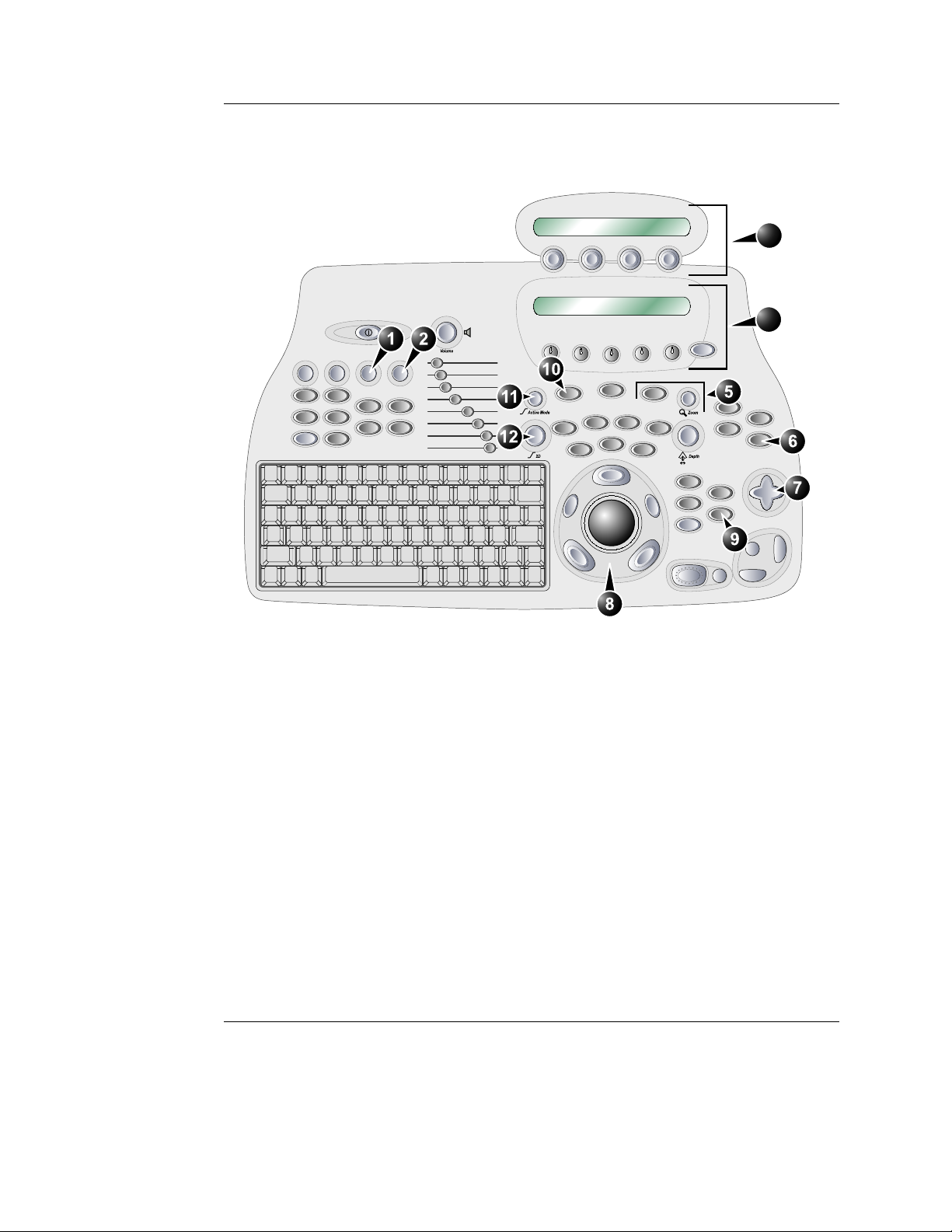
4D mode overview - Vivid 7 .......................................................... 7
Volume rendering mode screen............................................ 7
Slice mode screen ................................................................ 8
4D mode controls.................................................................. 9
Assigned rotaries and keys................................................. 10
4D mode assigned controls ................................................ 11
Additional 4D mode assigned controls ............................... 14
Soft menu controls.............................................................. 16
Trackball controls................................................................ 17
Display controls .................................................................. 19
Using 4D mode - Vivid 7.............................................................. 21
Parasternal view acquisition ............................................... 21
Apical view acquisition........................................................ 22
Full volume acquisition ....................................................... 23
Rotating/Translating the 4D image ..................................... 25
Zooming.............................................................................. 26
Cropping ............................................................................. 26
9 Slice................................................................................. 29
4D mode overview - EchoPAC PC ............................................. 32
4D/Multiplane Imaging User's Manual 1
FD092081-01
Page 4

Table of Contents
Volume rendering mode screen ..........................................32
Slice mode screen...............................................................33
4D mode control panel ........................................................34
Display controls................................................................... 36
Cropping..............................................................................37
Working with 4D acquisitions - EchoPAC PC ...........................39
9 Slice..................................................................................39
4D LV Volume application ...........................................................41
Starting the 4D LV Volume application — Vivid 7 ...............41
Starting the 4D LV Volume application — EchoPAC PC ....41
Chapter 2
4D Color Flow Imaging
Introduction ..................................................................................44
4D Color Flow mode overview - Vivid 7 .....................................45
Color Flow Volume rendering mode screen ........................45
Color Flow Slice mode screen.............................................46
4D Color Flow mode controls .............................................. 47
Assigned rotaries and keys .................................................48
4D Color Flow mode assigned controls...............................49
Additional 4D mode assigned controls ................................50
Soft menu controls ..............................................................51
Trackball controls ................................................................52
Display controls................................................................... 52
Using 4D Color Flow mode - Vivid 7...........................................54
Real time 4D Color flow acquisition.....................................54
Full volume Color Flow acquisition......................................55
6 Slice..................................................................................57
4D Color Flow mode overview - EchoPAC PC ..........................60
Volume rendering mode screen ..........................................60
Slice mode screen...............................................................61
4D mode control panel ........................................................62
Chapter 3
Multi-plane imaging
Introduction ..................................................................................66
2 4D/Multiplane Imaging User's Manual
FD092081-01
Page 5

Multi-plane mode overview - Vivid 7.......................................... 67
Bi-plane mode screen......................................................... 67
Tri-plane mode screen........................................................ 68
Multi-plane mode controls................................................... 69
Using Multi-plane mode imaging - Vivid 7 ................................ 77
Scan plane rotation............................................................. 78
Tilting scan plane 2............................................................. 78
Zooming.............................................................................. 79
Multi-plane mode overview - EchoPAC PC ............................... 82
Bi-plane mode screen......................................................... 82
Tri-plane mode screen........................................................ 83
The multi-plane control panel ............................................. 84
Working with multi-plane acquisitions - EchoPAC PC ............ 85
Chapter 4
Measurements and Analysis
Introduction.................................................................................. 88
Left ventricular volume measurements..................................... 89
Tri-plane acquisition............................................................ 89
Full volume acquisition ....................................................... 92
Rotation of the Volume reconstruction................................ 93
Bi-plane acquisition............................................................. 94
TSI surface model........................................................................ 96
To edit the sampling path ................................................... 97
Quantitative analysis................................................................... 98
Starting Quantitative analysis from a multi-plane
acquisition........................................................................... 98
Table of Contents
Chapter 5
Multi-plane Stress Echo
Introduction................................................................................ 102
Creating a Multi-plane stress test template ............................ 103
Launching the Template editor ......................................... 104
Stress Template setup...................................................... 104
Stress test acquisition .............................................................. 106
Baseline acquisitions ........................................................ 106
4D/Multiplane Imaging User's Manual 3
FD092081-01
Page 6

Table of Contents
Low dose and Peak dose level acquisitions......................109
Image analysis............................................................................112
Index
4 4D/Multiplane Imaging User's Manual
FD092081-01
Page 7
Introduction
This user manual describes the 4D and Multi-plane Imaging
applications for the Vivid 7 Dimension and
EchoPACPCDimension.
The 2D matrix probe 3V enables real time volume rendering,
simultaneous bi-plane or tri-plane data acquisition (multi-plane
acquisition).
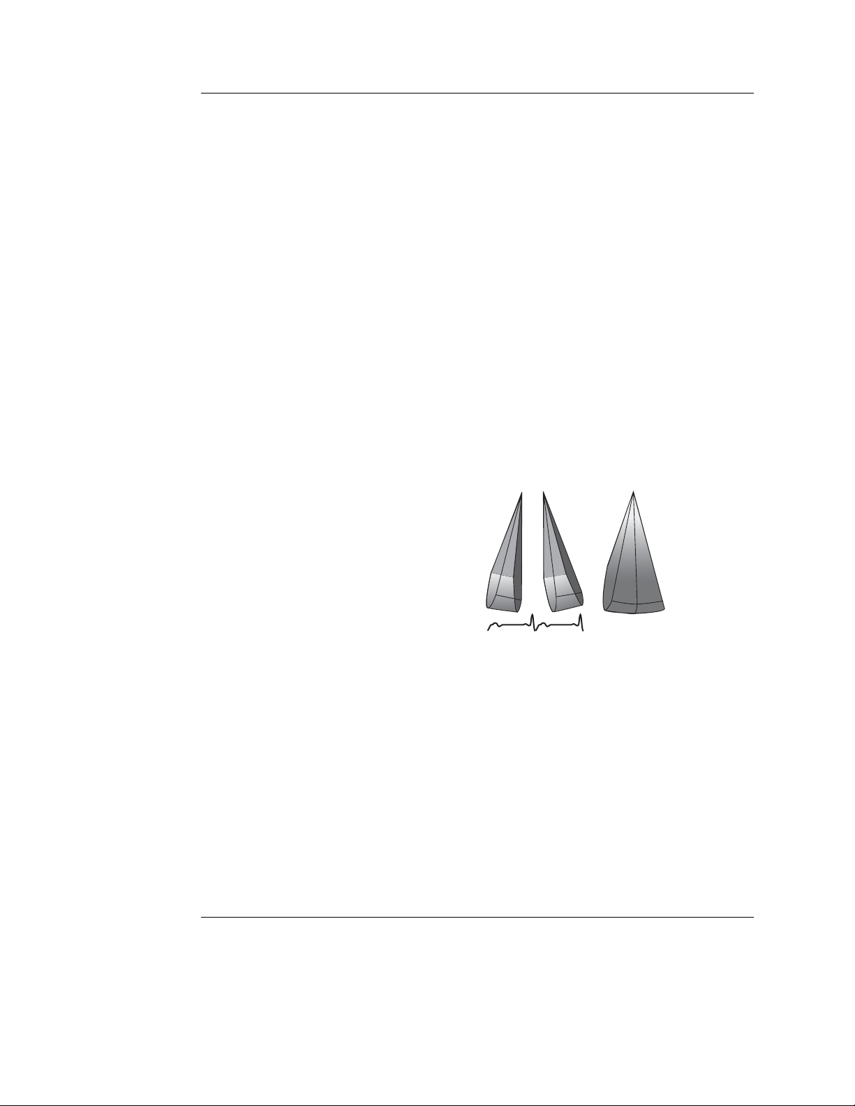
Introduction
1. Real time Volume acquisition (4D imaging)
2. Real time Bi-plane acquisition
3. Real time Tri-plane acquisition
4D imaging
4D imaging enables real time acquisition and rendering of
volume ultrasound data. Free rotation of the 3-dimensional
image combined with the zoom function and 4D image
optimization controls enhance spatial understanding of the
anatomical structure and function of the heart.
4D imaging is available in combination with B-Mode only.
4D/Multiplane Imaging User's Manual 1
FD092081-01
Page 8

Introduction
Multi-plane Imaging
Multi-plane imaging displays two (Bi-plane) or three (Tri-plane)
rotated scan planes acquired simultaneously. Free rotation,
tilting (in Bi-plane) of the scan planes and zoom enable the
investigation of anatomical structures from different angles.
Multi-plane imaging is available from B-Mode, Color flow mode
and TVI related modes.
If not otherwise specified, the term multi-plane means either
Bi-plane or Tri-plane.
Measurement and analysis
All cardiac measurements available in B mode are also
available in 4D and Multi-plane.
The 4D and Multi-plane modes enable the creation of a left
ventricular volume reconstruction based on contours drawn
from three cross sections at both end-systole and end-diastole
with calculation of end-systolic and end-diastolic volumes and
ejection fraction.
Multi-plane stress echo
Combined with specially designed Stress echo protocols,
Multi-plane mode enables faster stress tests as several views
can be acquired simultaneously.
Remark concerning the 3V probe
The 3V probe temperature will increase during extensive use,
due to heating from the probe electronics. If the probe reaches
its temperature limit, this will be detected by the system and
scanning will stop. Currently, this limit is set to 42.3 degrees
Celsius, which complies with regulatory instructions relating to
patient comfort and safety. This is reported with a dialog box
and the user has to wait until the temperature is below
acceptable limits before scanning can continue. This does not
in any way indicate probe malfunction. The user has to
unfreeze to start scanning again.
In order to reduce the chance for full freeze due to heating, the
system will reduce power slightly in a temperature interval just
2 4D/Multiplane Imaging User's Manual
FD092081-01
Page 9

Important
Introduction
below the full freeze limit. Changes to the power level are
reported in the status bar as Setting power level down and
Setting power level up.
The recommended use of this probe for live 4D and full volume
4D scanning is to enter full freeze whenever the probe is not
used for imaging. For other modalities no special actions are
required.
Read and understand all instructions in the Vivid 7 and
EchoPAC PC User manuals before attempting to use the
devices.
4D/Multiplane Imaging User's Manual 3
FD092081-01
Page 10
Introduction
Conventions used in this manual
Keys and button, on the control panel or alphanumeric
keyboard are indicated by over and underlined text (ex.
refers to the 2D mode key)
Bold type, describes button names on the screen.
Italic type: describes program windows, screens and dialogue
boxes.
Icons, highlight safety issues as follow:
Indicates that a specific hazard exists that, given inappropriate
conditions or actions, will cause:
DANGER
WARNING
• Severe or fatal personal injury
• Substantial property damage
Indicates that a specific hazard exists that, given inappropriate
conditions or actions, will cause:
• Severe personal injury
• Substantial property damage
2D
CAUTION
Indicates that a potential hazard may exist that, given
inappropriate conditions or actions, can cause:
• Minor injury
• Property damage
4 4D/Multiplane Imaging User's Manual
FD092081-01
Page 11

4D Imaging
Chapter 1
4D Imaging
• Introduction ................................................................................... ...... 6
• 4D mode overview - Vivid 7 .......................................................... ...... 7
• Volume rendering mode screen ................................................... 7
• Slice mode screen ........................................................................ 8
• 4D mode controls ......................................................................... 9
• Using 4D mode - Vivid 7 ............................................................... .... 21
• Parasternal view acquisition ....................................................... 21
• Apical view acquisition ............................................................... 22
• Full volume acquisition ............................................................... 23
• Rotating/Translating the 4D image ............................................. 25
• Zooming ..................................................................................... 26
• Cropping ..................................................................................... 26
• 9 Slice ........................................................................................ 29
• 4D mode overview - EchoPAC PC ............................................... .... 32
• Volume rendering mode screen ................................................. 32
• Slice mode screen ...................................................................... 33
• 4D mode control panel ............................................................... 34
• Display controls .......................................................................... 36
• Working with 4D acquisitions - EchoPAC PC ............................ .... 39
• 9 Slice ........................................................................................ 39
• 4D LV Volume application ............................................................ .... 41
• Starting the 4D LV Volume application — EchoPAC PC ........... 41
4D/Multiplane Imaging User's Manual 5
FD092081-01
Page 12

4D Imaging
Introduction
The 3V probe enables real time acquisition of volume
ultrasound data. Free rotation of the three-dimensional image
combined with zooming and 4D image optimization controls
enhance spatial understanding of the anatomical structure and
function of the heart.
Two display modes are available, Volume rendering mode for
three dimensional scanning and Slice mode for measurements
and volume reconstruction purpose.
4D imaging is available from B mode only.
6 4D/Multiplane Imaging User's Manual
FD092081-01
Page 13
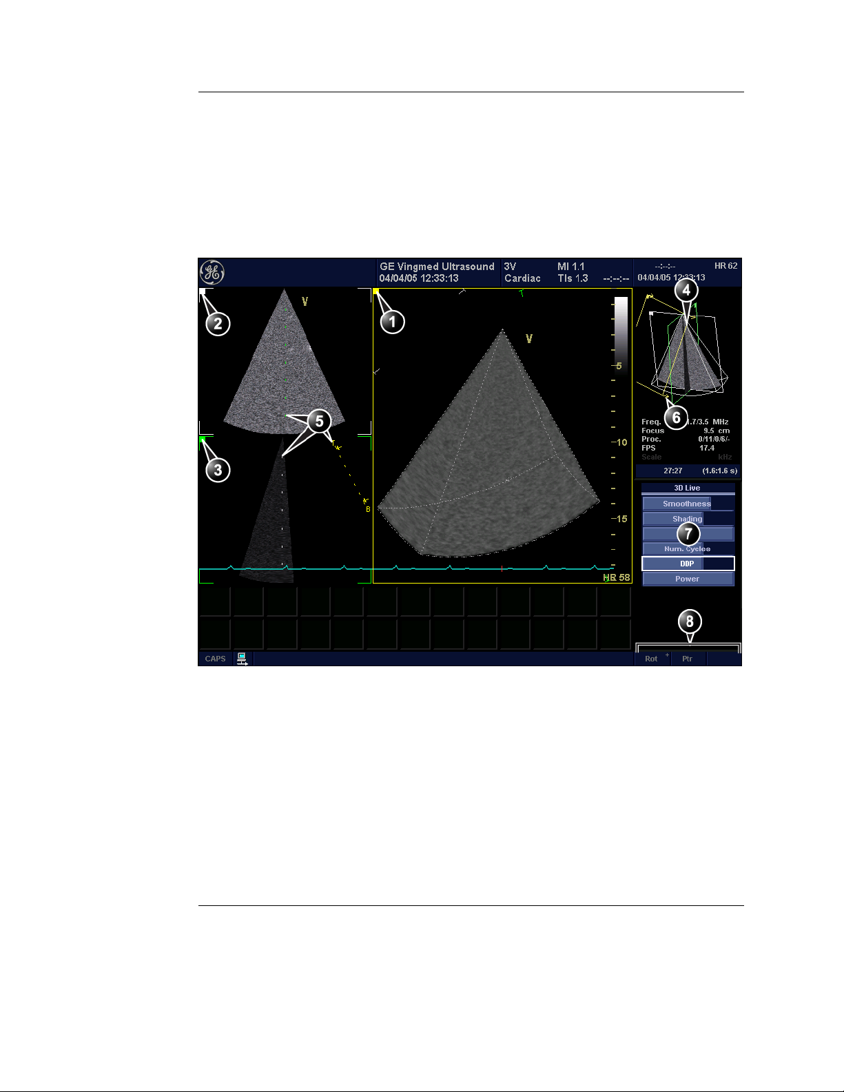
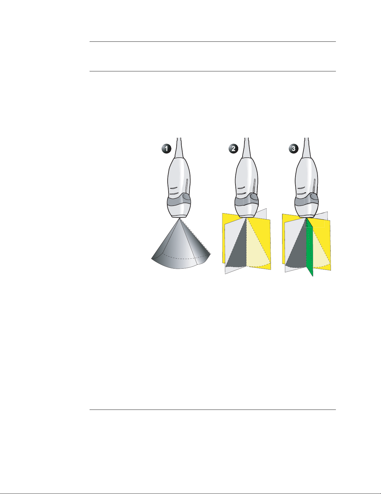
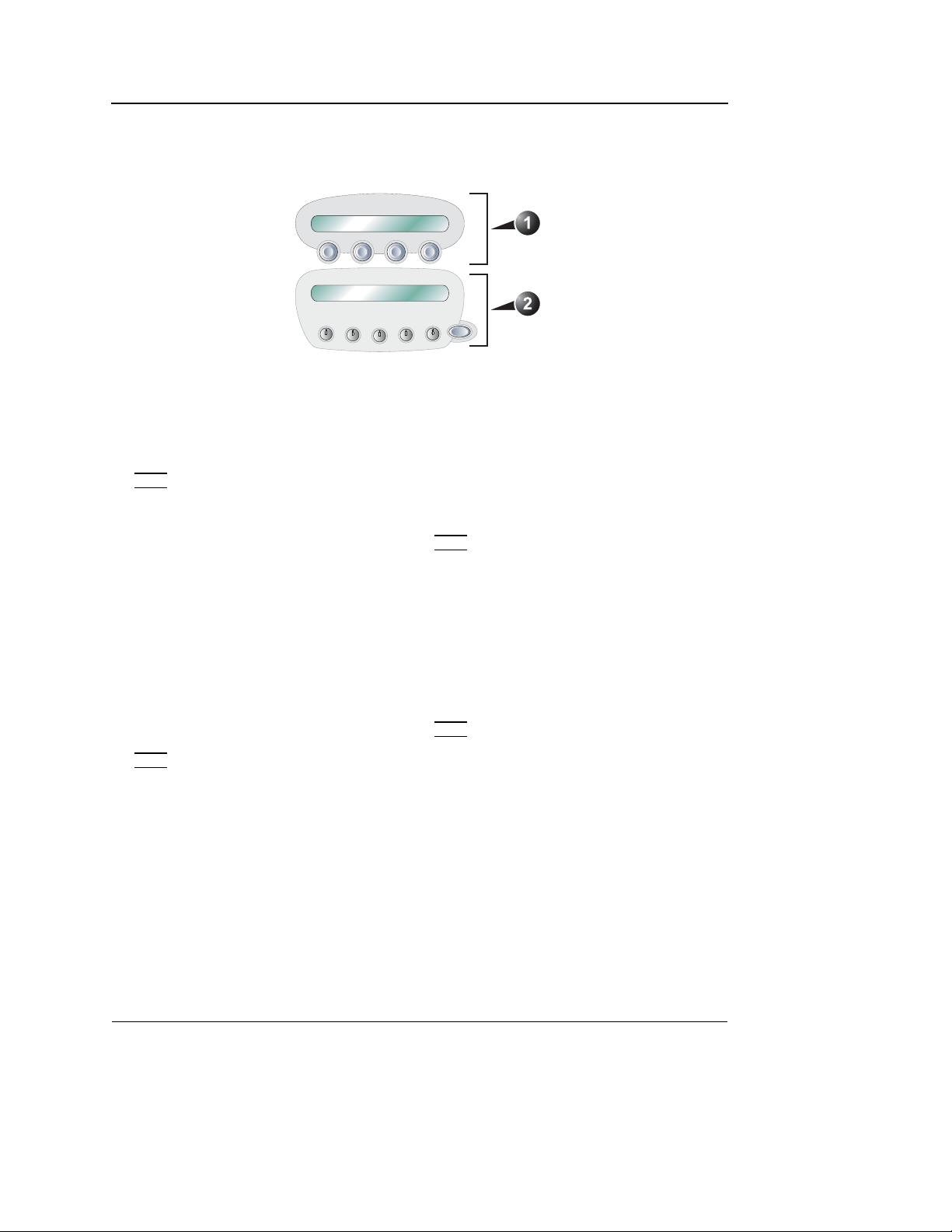
4D mode overview - Vivid 7
Volume rendering mode screen
The Volume rendering mode displays a volume rendering and
2D images from two perpendicular cut-planes.
4D Imaging
1. Volume rendering display from cut-plane 1 (yellow). The volume rendering may be adjusted by
rotating and translating the cut-plane 1.
2. Cut-plane 2 (white): 2D image in the azimuth plane.
3. Cut-plane 3 (green): 2D image in the elevation plane.
4. Orientation window: displays a three-dimensional model with cut-planes position and orientation.
5. Color coded cut-plane markers indicate the other cut-planes position relative to the displayed
cut-plane.
6. View direction marker.
7. Soft menu controls (see page 16)
8. Trackball functions (see page 17)
Figure 1-1: The 4D screen (Volume rendering)
4D/Multiplane Imaging User's Manual 7
FD092081-01
Page 14
4D Imaging
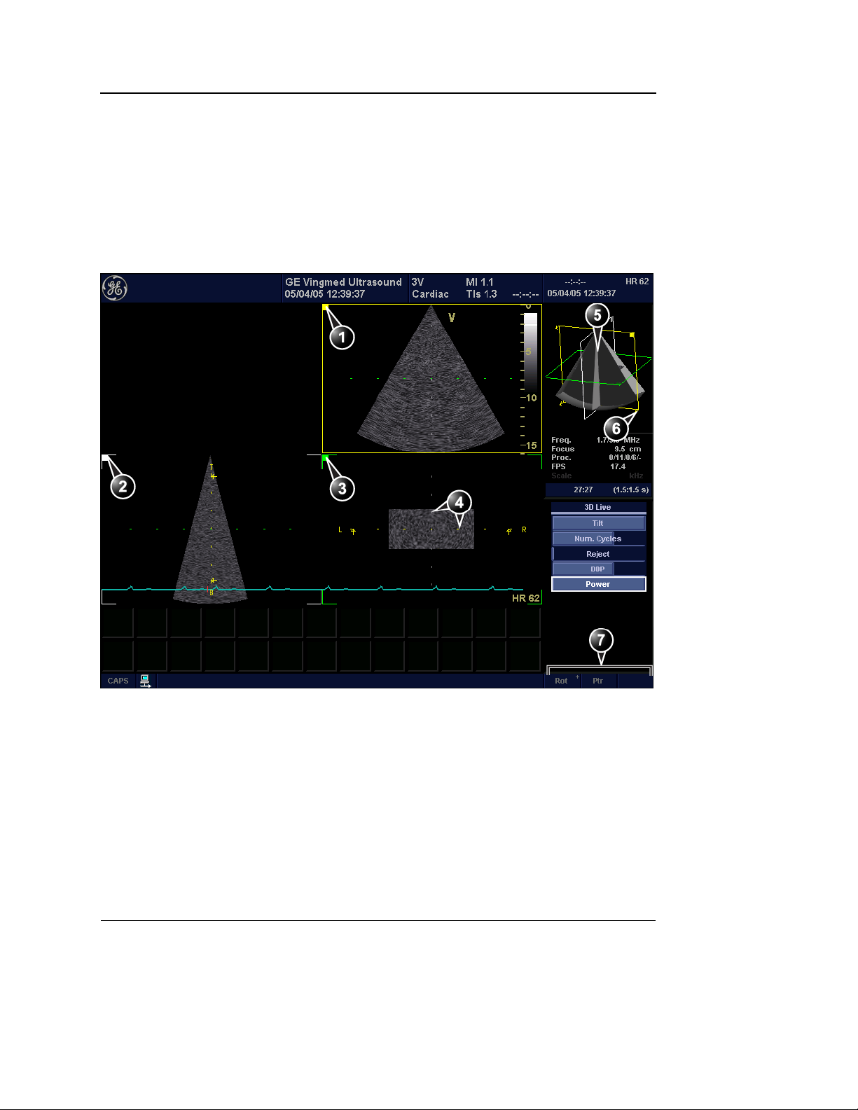
Slice mode screen
The Slice mode displays three cut-planes. The cut-planes can
be rotated and translated independently of each other. This
mode is use to perform measurements and volume
reconstruction based on contour traces done on several
cut-planes.
1. Cut-plane 1 (yellow)
2. Cut-plane 2 (white)
3. Cut-plane 3 (green)
4. Color coded cut-plane markers indicate the position of the other cut-planes relative to the displayed
cut-plane.
5. Orientation window: displays a three-dimensional model with cut-planes position.
6. View direction marker.
7. Trackball functions (see page 17)
Figure 1-2: The 4D screen (Slice mode)
8 4D/Multiplane Imaging User's Manual
FD092081-01
Page 15
4D mode controls
Alt. Alt. Alt. Alt.
4D Imaging
3
4
Width
Update /
ck
ll
a
a
Tr
B
Menu
1. 4D key
2. Multiplane key (see page 65)
3. Assigned 4D rotaries: see next page.
4. Assigned 4D keys: see next page.
5. Zoom/HR Zoom (see page 20)
6. Layout (see page 19): toggles the display
between:
• Multi screen with volume/slice
• Single screen volume/slice
7. Soft menu
8. Trackball (see page 17)
• Rotate/translate volume rendering or selected
cut-plane (Slice mode)
• Scroll through the cineloop
9. Clear: resets the orientation to default
positions.
10. Angle: predefined orientations optimized for
volume rendering.
11. 4D Gain
12. 2D Gain
Figure 1-3: The 4D controls on the control panel
4D/Multiplane Imaging User's Manual 9
FD092081-01
Page 16
4D Imaging
Assigned rotaries and keys
Volume rendering assigned controls
1. Assigned rotaries
• Width
• Frequency
• Focus position
• Volume size
MORE menu
• Translate R
Slice mode assigned controls
1. Assigned rotaries
• Width
• Rotate R
• Translate (in Freeze only) R
• Focus position
• Volume size
MORE menu
• Frequency
Controls marked with R are also available in cine replay.
Figure 1-4: Volume rendering and Slice mode assigned controls
2. Assigned keys
• Slice R
• Front/Back
• Crop (in Freeze only) R
• Box (in Freeze only) R
• Cineloop (in Freeze only) R
• Full volume
• 4D Colorize R
• 9 Slice (in Full volume Freeze only) R
MORE menu
• Up/Down R
• Flip R
• Orientation window R
• Cine rotate (in Freeze only) R
2. Assigned keys
• Slice exit R
• Reference plane R
• Cineloop (in Freeze only) R
MORE menu
• Up/Down R
• Orientation window R
10 4D/Multiplane Imaging User's Manual
FD092081-01
Page 17
4D Imaging
4D mode assigned controls
This section describes only the 4D mode controls. The
scanning mode controls are described in the system User
manual.
Width
(Volume rendering and Slice mode, Live)
Controls both elevation and azimuth widths, an increase of the
elevation width results in a decrease of the azimuth width.
Volume size
(Volume rendering and Slice mode, Live)
Controls the size of the volume. Adjusting the volume size may
affect the volume rate.
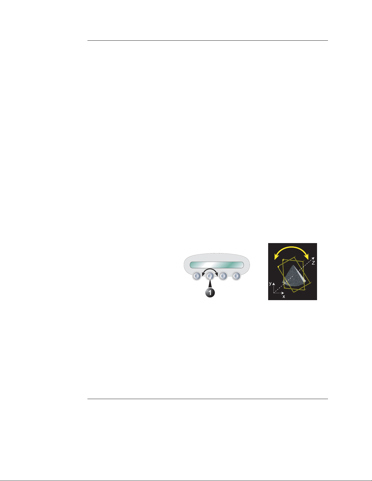
Rotate
(Slice mode, Live and Replay)
1. Rotate control
Rotate the selected cut-plane around the z-axis (see
Figure 1-5).
Figure 1-5: Cut-plane rotation around the z-axis
Slice/Slice exit
(Volume rendering and Slice mode, Live and Replay)
Toggles the display between Volume rendering (Figure 1-1)
and Slice mode (Figure 1-2).
4D/Multiplane Imaging User's Manual 11
FD092081-01
Page 18
4D Imaging
Front/Back
(Volume rendering, Live and Replay)
Tilts the volume in the elevation direction and rotates the view
position in one operation.
rendering display from different angles (Figure 1-6).
FRONT/BACK enables volume
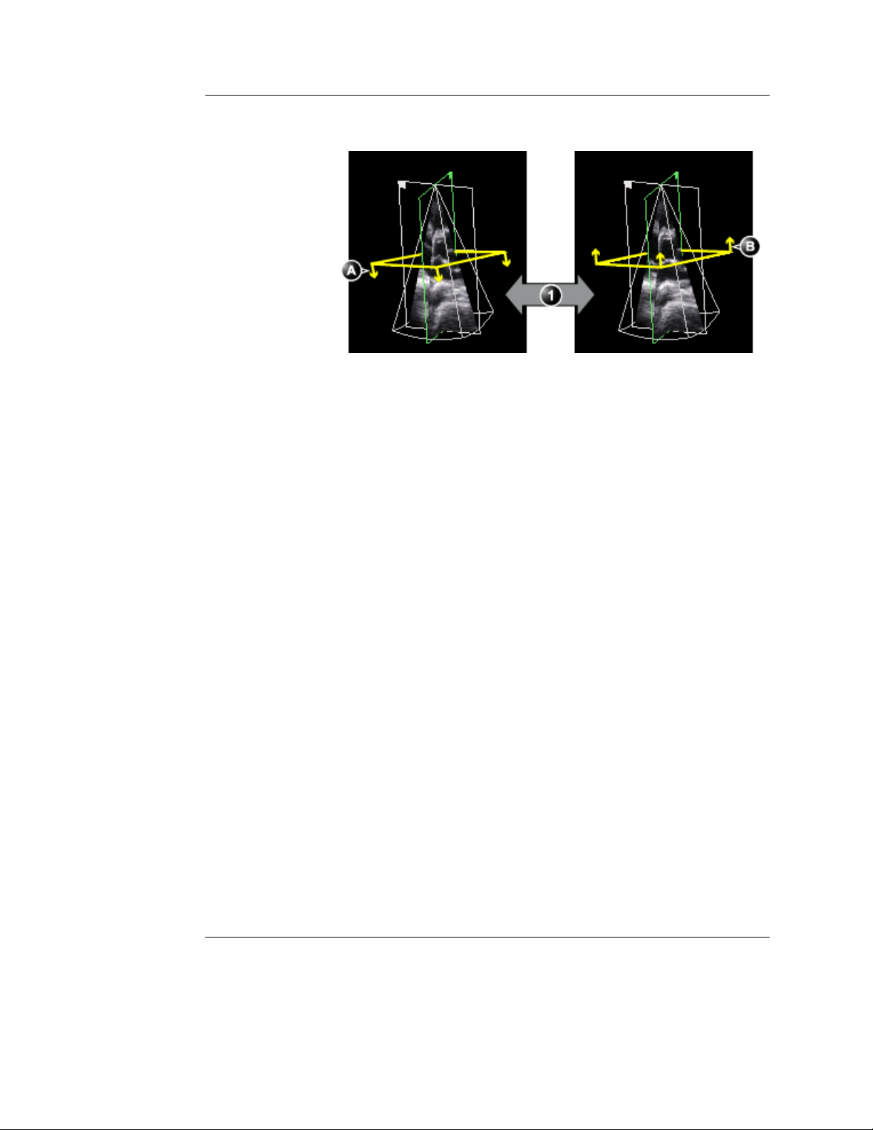
1. Front/Back: Volume tilt and View position rotation
A. Volume tilted to the left, view position looking towards the anterior wall.
B. Volume tilted to the right, view position looking towards the inferior wall.
Figure 1-6: Front/Back control on a PLAX volume
Reference plane
(Slice mode, Live and Replay)
Toggles the cut-plane selection between cut-plane 1, 2 or 3.
Crop (Free cropping)
(Volume rendering, Freeze and Replay)
12 4D/Multiplane Imaging User's Manual
FD092081-01
Page 19
4D Imaging
Removes all data up front of the active cut-plane. Cropping can
be applied on several parts of the volume by rotating/translating
the active cut-plane (see page 26).
Box (Box cropping)
(Volume rendering, Freeze and Replay)
Removes all data around a user-adjustable box (see page 27).
Full volume
(Volume rendering, Live)
Activates the ECG triggered sub-volume acquisition. This
technique enables the acquisition of a larger volume without
compromising the resolution, by combining several
sub-volumes acquired over two to six heart cycles (see
Figure 1-7). When acquisition is done for the number of heart
cycles set, the process is repeated replacing the oldest
sub-volumes.
+=
Figure 1-7: ECG triggered volume acquisition (two heart cycles)
4D Colorize
(Volume rendering, Live and Replay)
Adjusts the volume rendering color from a color map menu.
Depth encoded color maps
From this menu the user can also select a depth encoded color
map. These color maps use colors to improve the perception of
depth. Selecting the bronze/blue color map will display
structures that are close to the view plane with a bronze color.
Structures that are farther behind will be colored with a gray
4D/Multiplane Imaging User's Manual 13
FD092081-01
Page 20

4D Imaging
color, while the structures that are farthest behind will be
colored in blue. Very bright colors are almost white,
independent of the depth.
Stereo vision
4D Stereo vision is a display technique that enhances the
perception of depth in 3D renderings. This is achieved by
mixing two different volume renderings with slightly separated
viewing angles and presenting them separately to the user’s
left and right eyes. This feature requires the use of anaglyph
stereo glasses (glasses with one red and one cyan lens).
Normally you should be able to see the stereoscopic effect
after a few seconds. The effect may gradually improve after a
while. If you are already wearing glasses or lenses you should
not take them off, since the stereo effect then may be greatly
reduced.
Note: Not all users may be able to perceive depth using
stereoscopic display techniques.
Additional 4D mode assigned controls
The following controls are available after pressing MORE.
Up/Down
(Volume rendering and Slice mode, Live and Replay)
Flips the volume 180 degrees.
Flip
(Volume rendering, Live and Replay)
Flips the view position (Figure 1-8).
14 4D/Multiplane Imaging User's Manual
FD092081-01
Page 21
1. Flip control
A. View position looking downward
B. View position looking upward
Figure 1-8: Flip control
Orientation window
4D Imaging
(Volume rendering and Slice mode, Live and Replay)
Shows/hides the Orientation window.
Cine rotate
(Volume rendering, Replay)
Rotates back and forth the volume rendering.
4D/Multiplane Imaging User's Manual 15
FD092081-01
Page 22
4D Imaging
Soft menu controls
Soft menu controls are related to image quality adjustment.
These controls are accessed using the 4-way rocker on the
control panel. Only the 4D controls are described in this
section, refer to the system user manual for general imaging
controls.
Smoothness
(Volume rendering, Live and Replay)
Affects continuity of structures and image noise. Too much
smoothness will blur the image, too little will leave too much
noise.
Shading
(Volume rendering, Live and Replay)
Adjusts the shading effect on the image. Shading may improve
three dimensional perception.
Tilt
(Volume rendering, Live)
Tilts the volume in the elevation direction.
1. Tilt control: volume tilting in the elevation direction
Figure 1-9: Tilt control
16 4D/Multiplane Imaging User's Manual
FD092081-01
Page 23

4D Imaging
Number of Cycles
(Volume rendering, Live, Full volume acquisition)
Controls the number of cycles the ECG triggered full volume
acquisition is based on. Select between two, three, four or six
cycles. Four cycles is default setting.
DDP (Data Dependent Processing)
(Volume rendering, Live)
Performs temporal processing which reduces random noise
without affecting the motion of significant tissue structures.
UD Clarity
(Volume rendering, Freeze and Replay)
Enables the user to create a personalized appearance of the
tissue rendering by reducing noise and enhancing boundaries
between different structures. Adjustment toward the left creates
a smoother image. Adjustment toward the right creates a
crisper image.
Volume optimize
(Volume rendering, Live and Replay)
Optimizes the volume rendering by adjusting several display
controls simultaneously (e.g Shading, Smoothness... etc.).
Gamma
Adjusts the brightness of midtone values. A higher gamma
value produces an overall darker image, a lower gamma value
a lighter image.
Trackball controls
The trackball has multiple functions. The trackball functions are
organized in several functional groups as shown in the table
below.
The function selected is displayed in the lower right corner of
the screen (Figure 1-10).
• Press
within the active functional group. Groups with several
SELECT to toggle between the trackball functions
4D/Multiplane Imaging User's Manual 17
FD092081-01
Page 24
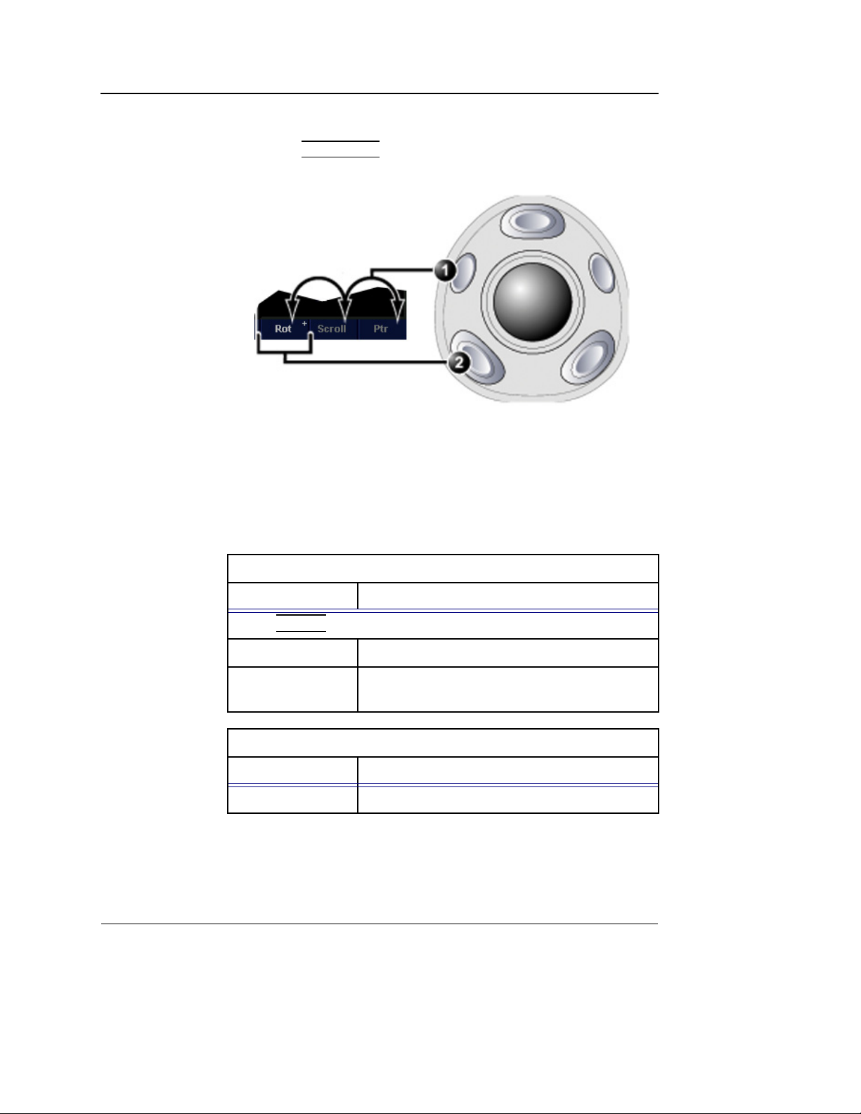
4D Imaging
functions are marked with a + symbol.
• Press
1. Trackball key: toggles between trackball functional groups.
2. Select key: toggles between the functions within the active group. Groups
with several functions are marked with a + symbol.
TRACKBALL to toggle between the functional groups.
Figure 1-10: The Trackball area
Orientation controls group
Function Description
Press
SELECT to toggle between the controls.
Rotate Rotates the volume rendering (see page 25).
Translate Translates the volume rendering (see
page 25).
Cineloop control group
Function Description
Scroll Scrolls through a cineloop.
18 4D/Multiplane Imaging User's Manual
FD092081-01
Page 25
4D Imaging
Display controls
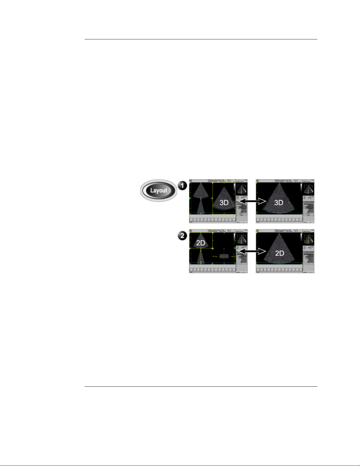
Layout key on the front panel
Toggles the display between multi-screen and single-screen.
• Multi-screen:
• In Volume rendering: displays a volume rendering and
2D images from two perpendicular cut-planes.
• In Slice mode: displays 2D images from three cut-planes
with the selected cut-plane in the main window.
• Single-screen:
• In Volume rendering: displays the volume rendering.
• In Slice mode: display the 2D image of the selected
cut-plane.
1. Display options for Volume rendering
2. Display options for Slice mode
Figure 1-11: 4D mode display options
4D Gain (Active Gain rotary)
Affects the image “depth” or transparency. Too much 4D Gain
applied will take away structures, too little will leave opaque
“Gray clouds” in the ventricle.
4D/Multiplane Imaging User's Manual 19
FD092081-01
Page 26

4D Imaging
Zoom
Display zoom
Activated and adjusted by rotating the
rectangular shape of the zoomed area is displayed in the
Orientation window.
High Resolution (HR) zoom
HR zoom concentrates the image processing to a magnified,
user selectable area in the image, resulting in a higher volume
rate in the selected image area.
To be able to use the HR zoom in 4D imaging the HR zoom
function must be activated in B mode before
imaging mode.
ZOOM rotary ( ). The
entering the 4D
20 4D/Multiplane Imaging User's Manual
FD092081-01
Page 27
Using 4D mode - Vivid 7
1. Select the 3V probe and cardiac application.
2. Create an examination.
Parasternal view acquisition
1. In 2D mode, acquire a PLAX view and optimize the image
quality, using
2. Press
4D.
3. Move the probe up or down so that the anterior wall is just
inside the image in the lower left window in the 4D screen
(Figure 1-12).
DEPTH, GAIN, TGC...etc.
4D Imaging
Note: In this position the volume is tilted to the left and the view position is looking
towards the anterior wall.
Figure 1-12: PLAX volume rendering
4. Adjust 4D Gain to optimize the depth impression of the
back wall.
5. To display a volume looking towards the inferior wall, press
FRONT/BACK.
The volume is tilted to the right and the view position is
rotated 180 degrees.
4D/Multiplane Imaging User's Manual 21
FD092081-01
Page 28

4D Imaging
6. Press FREEZE, 2D FREEZE and rotate the volume to check
the result.
7. Press
IMG. STORE.
Apical view acquisition
1. In 2D mode, acquire a Apical view and optimize the image
quality, using
2. Press
4D and follow the same procedure as for the PLAX
view (see page 21).
Make sure to assess the image quality in the reference
views and the volume rendering. Use
display the volume correctly.
3. Press
FREEZE, 2D FREEZE and rotate the volume to check
the result.
4. Press
IMG. STORE.
DEPTH, GAIN, TGC...etc.
FRONT/BACK to
22 4D/Multiplane Imaging User's Manual
FD092081-01
Page 29

4D Imaging
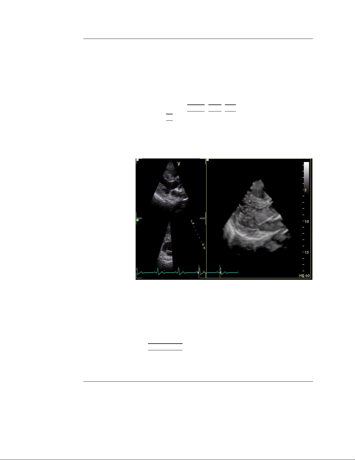
Full volume acquisition
Full volume acquisition is based on ECG triggering acquisition
of sub-volumes. This technique enables the acquisition of a
larger volume without compromising the resolution, by
combining several sub-volumes acquired over two, three, four
or six heart cycles (see Figure 1-7, page 13). When acquisition
is done for the number of heart cycles set, the process is
repeated replacing the oldest sub-volumes.
ECG triggering acquisition may by nature contain artifacts.
CAUTION
Artifacts may be caused by:
• Movements of the probe caused by the operator during
acquisition.
• Movements of the patient during acquisition.
• Irregular heart rate during acquisition.
To validate the acquisition, perform a visual inspection in both
the volume rendering and the elevation plane. Stitching artifacts
are shown as visible transitions between the sub-volumes
(Figure 1-13)
To avoid spatial artifacts, make sure that the probe and the
patient are not moving during the acquisition. The patient
should, if possible hold his/her breath. The ECG trace should
be stable.
1. Connect the ECG device and make sure to obtain a stable
ECG trace.
2. In 2D mode, acquire an Apical view and optimize the image
quality, using
3. Press
4. Press
4D.
FULL VOLUME.
DEPTH, GAIN, TGC...etc.
The Full volume acquisition is started.
5. You may adjust
ANGLE to get different view. The default
top/down view is best for stitching quality assessment.
6. Ask the patient to hold her/his breath at end expiration.
Keep the probe steady and look for stitching artifacts in both
the volume rendering and the elevation plane in the lower
left window of the screen (Figure 1-13).
Attention should be brought on stitching quality during
acquisition rather than volume rendering quality.
4D/Multiplane Imaging User's Manual 23
FD092081-01
Page 30
4D Imaging
A: Acquisition with stitching artifacts
1. Elevation plane
2. Volume rendering
B: Acquisition without stitching artifacts
1. Elevation plane
2. Volume rendering
Figure 1-13: Stitching quality assessment
When no artifacts are seen over a few heart cycles, press
FREEZE.
24 4D/Multiplane Imaging User's Manual
FD092081-01
Page 31

4D Imaging
Note: it is recommended to acquire several heart cycles
and use
7. Once in Freeze, adjust
the result and tress
SELECT CYCLE to select the best one.
4D GAIN. Rotate the volume to check
IMG. STORE.
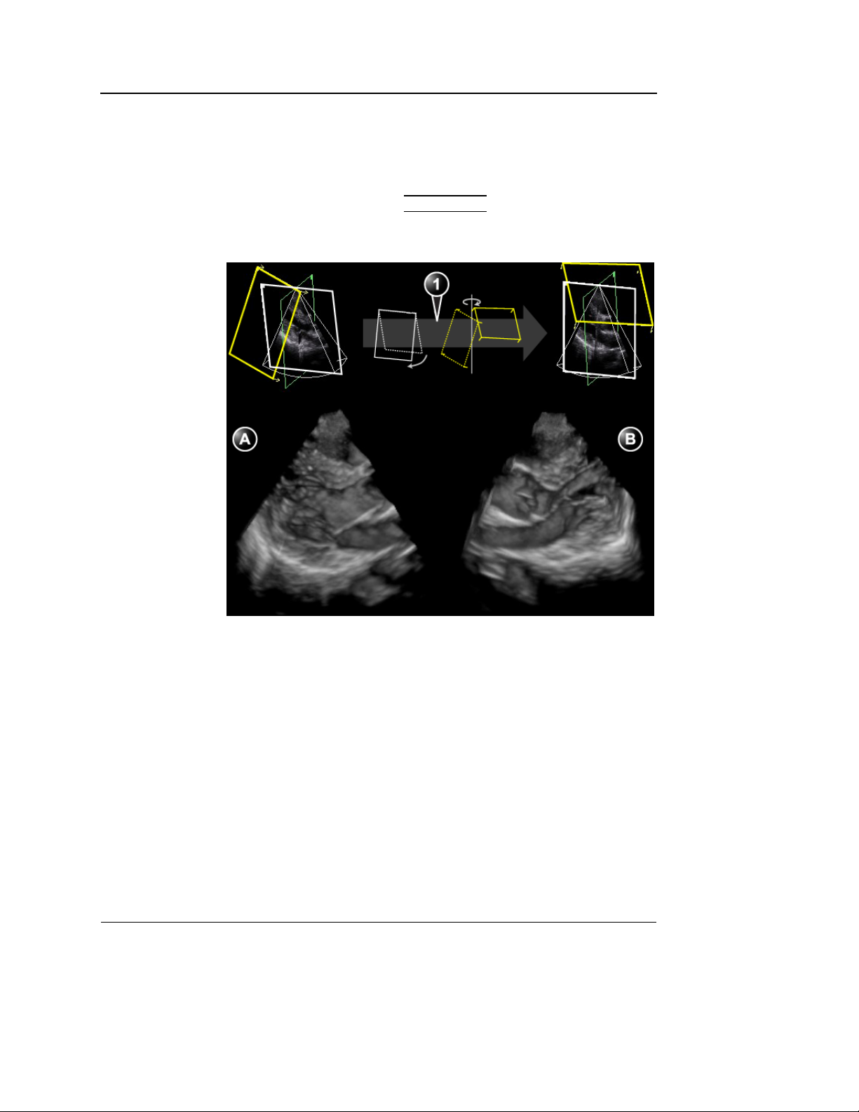
Rotating/Translating the 4D image
Translation and rotation can be performed in either Volume
rendering or Slice mode. Press
modes.
1. Move the trackball to rotate or translate the cut-plane
according to the trackball function selected.
2. Press
SELECT to toggle between Rotate and Translate.
Move the trackball to apply the selected control (see
Figure 1-14).
The default position can be displayed again by pressing
CLEAR.
SLICE to toggle between the two
1. Select the trackball control “Translate” and use the trackball to translate the
cut-plane.
2. Select the trackball control “Rotate” and use the trackball to rotate the
cut-plane (all directions).
Figure 1-14: Rotating/translating the 4D image
4D/Multiplane Imaging User's Manual 25
FD092081-01
Page 32

4D Imaging
1. Zoomed area
Zooming
1. Rotate the ZOOM knob clockwise on the control panel.
The volume rendering is magnified. The frame of the
Volume rendering cut-plane in the Orientation window is
updated showing the magnified portion of the volume
(Figure 1-15).
Figure 1-15: The Orientation window in zoom mode
Cropping
There are two cropping tools available: Free cropping tool and
Box cropping tool.
The Free cropping tool removes all data up front of the active
cut-plane. Cropping can be applied on several parts of the
volume by rotating/translating the active cut-plane.
The Box cropping tool removes all data around a
user-adjustable box.
It is not possible to use both cropping tools on the same
acquisition.
Free cropping
The Free cropping tool is available in Volume rendering mode,
when in Freeze or in Replay.
1. While in Volume rendering live mode, press
2. Press
Note: Pressing
cropping operations.
3. Rotate and translate the active cut-plane.
All data above the cut-plane will be removed when
applying crop.
CROP.
CROP will remove any previous Box
FREEZE.
26 4D/Multiplane Imaging User's Manual
FD092081-01
Page 33

4D Imaging
4. Press SET to apply crop.
All data up front of the active cut-plane is removed.
5. Repeat steps 3 and 4 to remove other parts of the volume.
Note: press
stepwise.
Press
operation.
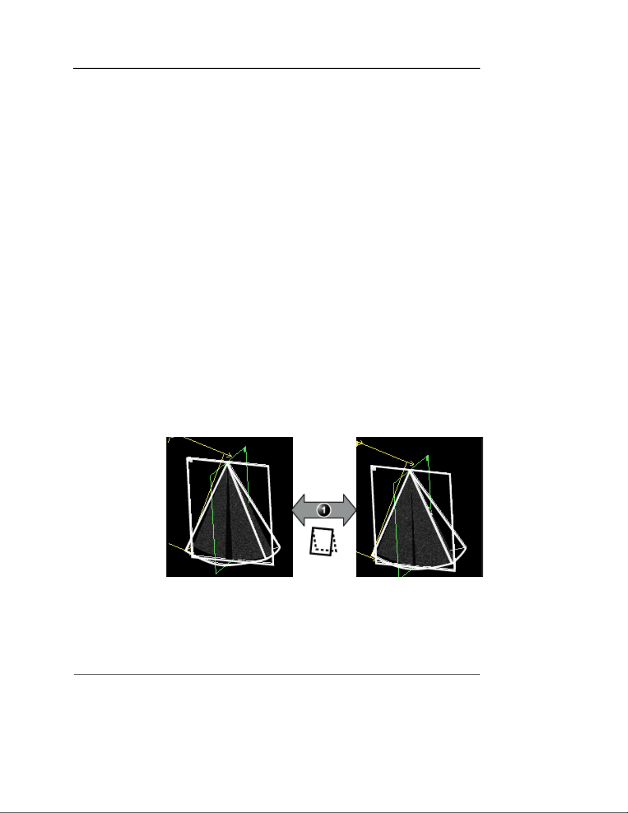
Box cropping
The Box cropping tool is available in Volume rendering mode,
when in Freeze or in Replay.
1. While in Volume rendering live mode, press
2. Press
A box frame is displayed with two adjustable sides
(highlighted as red and blue), see Figure 1-16.
Note: Pressing
cropping operations.
3. Rotate the
corresponding sides around the structure of interest.
All data outside the box is removed.
4. Rotate the
sides of the box.
5. Repeat steps 3 and 4 to adjust the selected sides of the box
until the structure of interest is within the box.
Note: press
6. Press
UNDO CROP to undo the cropping actions
REMOVE CROP to undo all cropping actions in one
FREEZE.
BOX.
BOX will remove any previous Free
RED and BLUE assigned rotaries to adjust the
BOX SIDES assigned rotary to select two other
RESET BOX to undo the box adjustments.
BOX EXIT to apply and exit box cropping.
4D/Multiplane Imaging User's Manual 27
FD092081-01
Page 34

4D Imaging
1. Default cropping box with two active sides (red and blue). The other sides can
be selected for adjustment
2. Cropped volume (from upper and lower sides)
Figure 1-16: Box cropping
28 4D/Multiplane Imaging User's Manual
FD092081-01
Page 35

4D Imaging
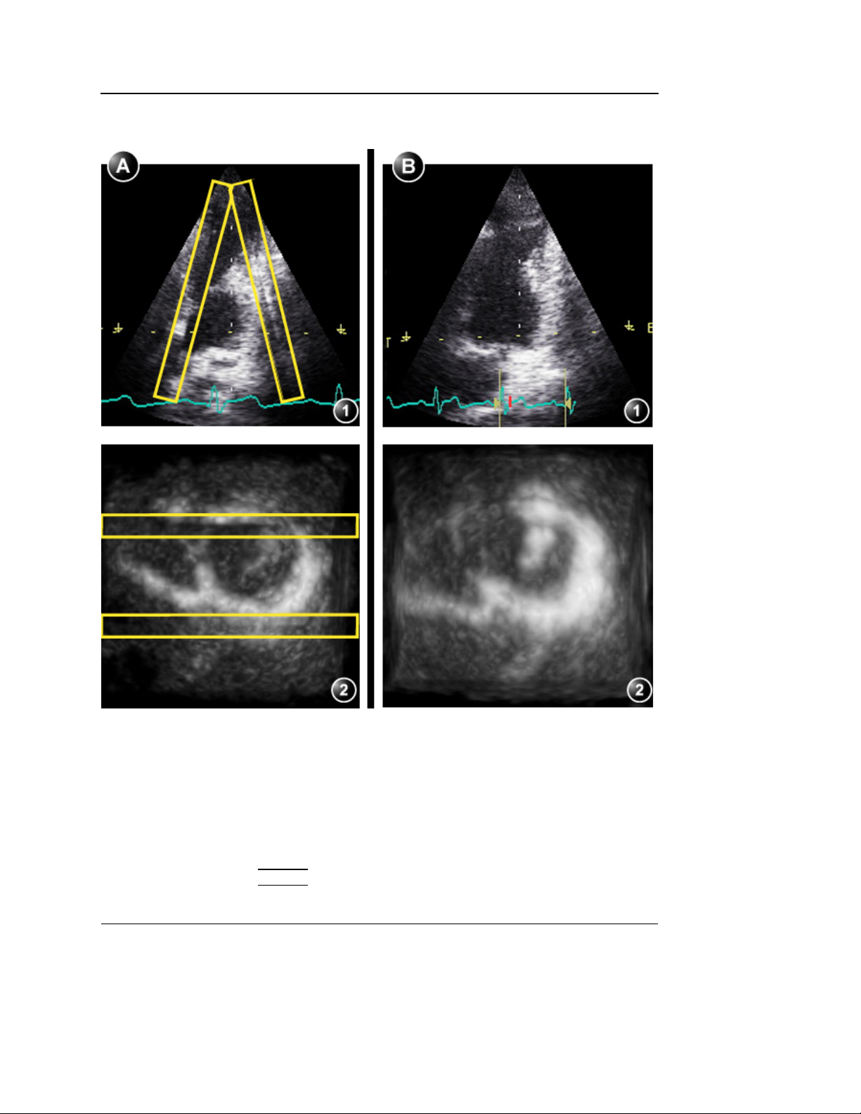
9 Slice
9 Slice enables simultaneous display of nine short axis views
generated from an Apical full volume acquisition.
9 Slice is available only from a full volume acquisition when in
Freeze.
1. Acquire an apical Full volume view (see page 23).
2. Press
3. Press
The 9Slice screen is displayed showing nine short axis
views (Figure 1-17). The slices are evenly distributed and
maximized in size for best assessment.
FREEZE.
9SLICE.
1. Upper slice
2. Lower slice
Figure 1-17: 9 Slice screen
If required, zoom in. All slices are zoomed in
simultaneously.
4. The following adjustments can be done:
• Adjust
TOP and BOTTOM controls to change the slicing
area (Figure 1-18).
4D/Multiplane Imaging User's Manual 29
FD092081-01
Page 36

4D Imaging
1. Top: upper slice adjustment
2. Bottom: lower slice adjustment
Figure 1-18: Slice distribution adjustment
• Adjust the AXIS 1 and AXIS 2 controls to rotate the slices
backward/forward and sideways (Figure 1-19), to align
the slices with the anatomical structure.
1. Axis 1: slice rotation backward/forward
2. Axis 2: slice rotation sideways
Figure 1-19: Slice rotation adjustment
30 4D/Multiplane Imaging User's Manual
FD092081-01
Page 37

5. Press IMG. STORE to save.
4D Imaging
4D/Multiplane Imaging User's Manual 31
FD092081-01
Page 38

4D Imaging
4D mode overview - EchoPAC PC
4D acquisitions from Vivid 7 can be opened and post
processed on the EchoPAC PC workstation. This section
describes the controls and procedures related to 4D mode on
the workstation. Refer to the EchoPAC PC User manual about
general use of the workstation.
Volume rendering mode screen
1. Volume rendering display from cut-plane 1 (yellow). The volume rendering may be adjusted by
rotating and translating the cut-plane 1.
2. Cut-plane 2 (white): 2D image in the azimuth plane.
3. Cut-plane 3 (green): 2D image in the elevation plane.
4. Orientation window: displays a three-dimensional model with cut-planes position and orientation.
5. Color coded cut-plane markers indicate the other cut-planes position relative to the displayed
cut-plane.
6. 4D control panel (Volume rendering mode)
Figure 1-20: The 4D screen (Volume rendering)
32 4D/Multiplane Imaging User's Manual
FD092081-01
Page 39

Slice mode screen
4D Imaging
1. Cut-plane 1 (yellow)
2. Cut-plane 2 (white)
3. Cut-plane 3 (green)
4. Color coded cut-plane markers indicate the position of the other cut-planes relative to the displayed
cut-plane.
5. View direction marker.
6. Orientation window: displays a three-dimensional model with cut-planes position.
7. 4D control panel (Slice mode)
Figure 1-21: The 4D screen (Slice mode)
4D/Multiplane Imaging User's Manual 33
FD092081-01
Page 40

4D Imaging
4D mode control panel
Refer to ’4D mode controls’ on page 9 for information on
the 4D related controls. All other general imaging controls
are described in the workstation User manual.
Figure 1-22: The 4D Control panel
34 4D/Multiplane Imaging User's Manual
FD092081-01
Page 41

4D Imaging
Rendering controls
In volume rendering, select Rendering to display the rendering controls.
Figure 1-23: Rendering and orientation panel
4D/Multiplane Imaging User's Manual 35
FD092081-01
Page 42

4D Imaging
Display controls
Rotation
Rotation using the mouse
1. Place the mouse cursor in the image area.
2. Press and hold down the Left mouse button and drag the
mouse in any direction.
The volume rendering is rotated following the mouse
cursor movement.
To rotate around the Z axis, press and hold down
drag the mouse to the left or right.
Rotation from the control panel
1. In Volume rendering, Select Rendering.
The Rendering control panel is displayed (see
Figure 1-23).
2. Adjust Rotate X, Rotate Y or Rotate Z to rotate the volume
rendering around the corresponding axis.
ALT and
Figure 1-24: Rotation around the X, Y and Z axis
Translation
Translation using the mouse
1. Place the mouse cursor in the image area.
2. Press and hold down
down.
The volume rendering cut-plane is translated.
Translation from the control panel
1. In Volume rendering, Select Rendering.
The Rendering control panel is displayed (see
Figure 1-23).
2. Adjust the control Translate.
SHIFT and drag the mouse up or
36 4D/Multiplane Imaging User's Manual
FD092081-01
Page 43

4D Imaging
Zoom
Zooming
1. Rotate the Mouse wheel to zoom in and out.
OR
Press
OR
Adjust Zoom on the control panel.
Zoom panning
1. While in zoom mode, press and hold down the mouse
wheel and drag the mouse.
OR
Press and hold down
ARROW UP to zoom in, ARROW DOWN to zoom out.
SHIFT and press the ARROW keys.
Cropping
Free cropping
1. Select Rendering.
The Rendering control panel is displayed (see
Figure 1-23).
2. Select Crop.
Note: Pressing Crop will remove any previous Box
cropping operations.
3. Rotate and translate the active cut-plane.
All data above the cut-plane will be removed when
applying crop.
4. Press Set to apply crop.
All data up front of the active cut-plane is removed.
5. Repeat steps 3 and 4 to remove other parts of the volume.
Note: press Undo to undo the cropping actions stepwise.
Press Remove crop to undo all cropping actions in one
operation.
6. Press Crop to exit the Free cropping tool.
Box cropping
1. Select Rendering.
The Rendering control panel is displayed (see
Figure 1-23).
2. Select Box.
A box frame is displayed with two adjustable sides
(highlighted as red and blue), see Figure 1-25.
4D/Multiplane Imaging User's Manual 37
FD092081-01
Page 44

4D Imaging
Note: Pressing Box will remove any previous Free
cropping operations.
3. Use the Red and Blue controls to adjust the corresponding
sides around the structure of interest.
All data outside the box is removed.
4. Use the Box Sides control to select two other sides of the
box.
5. Repeat steps 3 and 4 to adjust the selected sides of the box
until the structure of interest is within the box.
Note: Press Reset Box to undo all cropping actions in one
operation.
6. Press Box to apply and exit Box cropping tool.
1. Default cropping box with two active sides (red and blue). The other sides can
be selected for adjustment
2. Cropped volume (from upper and lower sides)
Figure 1-25: Box cropping
38 4D/Multiplane Imaging User's Manual
FD092081-01
Page 45

4D Imaging
Working with 4D acquisitions - EchoPAC PC
1. In the Search/Create patient window (Archive menu), select
a patient record with 4D acquisitions.
The Examination List window is displayed.
2. Select the desired examination and open (double-click) a
4D acquisition from the clipboard.
OR
Press Image browser and open (double-click) the 4D
acquisition in the Image browser screen.
The Volume rendering mode screen is displayed (see
Figure 1-20, page 32).
3. Rotate and translate the volume rendering to display the
structure of interest (see page 36).
4. Optimize the volume rendering using 4D Gain,
Smoothness, Shading controls.
5. If desired, double-click on the image area to display the
volume rendering in a single screen.
6. If desired, zoom in the structure of interest (see page 37).
7. If necessary, use the cropping tools to remove unwanted
structures (see page 37).
8. If desired, press Cine rotate to rotate the volume rendering
back and forth.
9. Press Store to save the changes.
9 Slice
9 Slice enables simultaneous display of nine short axis views
generated from an Apical full volume acquisition.
1. Select an Apical full volume acquisition.
2. Press 9 Slice.
The 9Slice screen is displayed showing nine short axis
views. The slices are evenly distributed and maximized in
size for best assessment.
If required, zoom in. All slices are zoomed in
simultaneously.
3. The following adjustments can be done:
• Adjust Top and Bottom controls to change the slicing
area.
• Adjust the Axis 1 and Axis 2 controls to rotate the slices
4D/Multiplane Imaging User's Manual 39
FD092081-01
Page 46

4D Imaging
backward/forward and sideways, to align the slices with
the anatomical structure.
4. Press Store to save.
40 4D/Multiplane Imaging User's Manual
FD092081-01
Page 47

4D LV Volume application
The 4D LV Volume function may be analyzed on the Vivid 7
system or EchoPAC PC workstation using the TomTec
4D LV-Volume application. The 4D LV-Volume application
enables analysis of global and regional volume measurement
from a Full volume tissue acquisition.
The 4D LV-Volume application is an option.
Measurements generated in the 4D LV-Volume application are
saved to the worksheet. The measurements have a specific
TomTec label.
In addition 4D tissue acquisitions can be stored on a removable
media to a format compatible with the TomTec application using
the “Save as” function on the Vivid 7 system or the
EchoPAC PC workstation (File format: VolDicom (*.dcm)).
Refer to the Vivid 7 or EchoPAC PC user manual for additional
information on the “Save as” function.
Starting the 4D LV Volume application
— Vivid 7
4D Imaging
1. In a 4D Full volume tissue acquisition, press MEASURE.
2. Select Volume and 4D LV Volume in the Measurement
menu.
The 4D LV-Volume application is started.
Refer to the TomTec 4D LV-Volume User manual for proper
use of the application.
Starting the 4D LV Volume application
— EchoPAC PC
1. In a 4D Full volume tissue acquisition, select 4D LV
Volume on the control panel.
The 4D LV-Volume application is started.
Refer to the TomTec 4D LV-Volume User manual for proper
use of the application.
Note: the 4D LV Volume application can also be started
from the Measurement menu as described for the Vivid 7
above, and from the Rendering and orientation panel
(Figure 1-23).
4D/Multiplane Imaging User's Manual 41
FD092081-01
Page 48

4D Imaging
42 4D/Multiplane Imaging User's Manual
FD092081-01
Page 49

4D Color Flow Imaging
Chapter 2
4D Color Flow Imaging
• Introduction ................................................................................... .... 44
• 4D Color Flow mode overview - Vivid 7 ...................................... .... 45
• Color Flow Volume rendering mode screen ............................... 45
• Color Flow Slice mode screen ................................................... 46
• 4D Color Flow mode controls ..................................................... 47
• Using 4D Color Flow mode - Vivid 7 ........................................... .... 54
• Full volume Color Flow acquisition ............................................. 55
• 6 Slice ........................................................................................ 57
• 4D Color Flow mode overview - EchoPAC PC ........................... .... 60
• Real time 4D Color flow acquisition ........................................... 54
• Volume rendering mode screen ................................................. 60
• Slice mode screen ...................................................................... 61
• 4D mode control panel ............................................................... 62
4D/Multiplane Imaging User's Manual 43
FD092081-01
Page 50

4D Color Flow Imaging
Introduction
The 4D Color Flow Imaging mode enables real time volume
rendering display with color flow data. 4D Color Flow imaging
based on Full volume acquisition is available.
44 4D/Multiplane Imaging User's Manual
FD092081-01
Page 51

4D Color Flow Imaging
4D Color Flow mode overview - Vivid 7
Color Flow Volume rendering mode screen
1. Volume rendering display with Color Flow
2. 2D Color Flow image in the azimuth plane
3. 2D Color Flow image in the elevation plane
4. Orientation window: displays a three-dimensional model with cut-planes position and orientation.
5. Soft menu controls (see page 51)
6. Trackball functions (see page 52)
Figure 2-1: 4D Color Flow screen (Volume rendering)
4D/Multiplane Imaging User's Manual 45
FD092081-01
Page 52

4D Color Flow Imaging
Color Flow Slice mode screen
1. Cut-plane 1 (yellow)
2. Cut-plane 2 (white)
3. Cut-plane 3 (green)
4. Trackball functions (see page 52)
Figure 2-2: 4D Color Flow screen (Slice mode)
46 4D/Multiplane Imaging User's Manual
FD092081-01
Page 53

4D Color Flow mode controls
Both Tissue and Color flow mode controls are available. Press
ACTIVE MODE to toggle between the two modes.
Alt. Alt. Alt. Alt.
4D Color Flow Imaging
3
4
Width
13
Update /
ck
ll
a
a
Tr
B
Menu
1. 4D key
2. Multiplane key
3. Assigned 4D rotaries: see next page.
4. Assigned 4D keys: see next page.
5. Zoom (see page 20)
6. Layout (see page 19): toggles the display
between:
• Multi screen with volume/slice
• Single screen volume/slice
7. Soft menu (see page 51)
8. Trackball (see page 52)
• Rotate/translate volume rendering or selected
cut-plane (Slice mode)
• Scroll through the cineloop
9. Clear: resets the orientation to default
positions.
10. Angle: predefined orientations optimized for
volume rendering.
11. Color Gain
12. 2D Gain
13. Color key
Figure 2-3: 4D Color Flow mode controls on the control panel
4D/Multiplane Imaging User's Manual 47
FD092081-01
Page 54

4D Color Flow Imaging
Assigned rotaries and keys
Color Flow Volume rendering assigned controls
1. Assigned rotaries
• Scale
• Baseline R
• Volume size
MORE menu
• Translate R
Color Flow Slice mode assigned controls
1. Assigned rotaries
• Rotate R
• Translate (in Freeze only) R
Controls marked with R are also available in cine replay.
2. Assigned keys
• Slice R
• Invert
• Crop (in Freeze only) R
• Box (in Freeze only) R
• Cineloop (in Freeze only) R
• 4D CF Prepare
• Full Volume
• Color map R
• 6 Slice (in Full volume Freeze only) R (page 57)
MORE menu
• Up/Down R
• Flip R
• Orientation window R
• Cine rotate (in Freeze only) R
• Variance
• 4D Colorize R
2. Assigned keys
• Slice exit R
• Reference plane R
• Cineloop (in Freeze only) R
MORE menu
• Up/Down R
• Orientation window R
Figure 2-4: Color Flow Volume rendering and Slice mode assigned
controls
48 4D/Multiplane Imaging User's Manual
FD092081-01
Page 55

4D Color Flow Imaging
4D Color Flow mode assigned controls
Scale
Adjusts the repetition rate of the Doppler pulses transmitted to
acquire the data for color flow mapping. The Scale (Nyquist
limit) should be adjusted so that no aliasing occurs, while still
having good resolution of velocities. The Nyquist limit should
be somewhat above the maximum velocity found in the data.
Baseline
Adjusts the color map to emphasize flow either toward or away
from the probe.
Volume size
The volume size control enables the adjustment of the color
ROI. ROI adjustment may affect volume rate and/or resolution.
Slice/Slice exit
Toggles the display between Volume rendering and Slice
mode.
Invert
Enables the color scheme assigned to positive and negative
velocities to be inverted.
Variance
Controls the amount of variance data added to a color display.
Variance enables computer-aided detection of turbulent flow
(e.g. jets or regurgitation).
4D Colorize
(Volume rendering, Live and Replay)
Adjusts the volume rendering color from a color map menu.
Reference plane
(Slice mode, Live and Replay)
Toggles the cut-plane selection between cut-plane 1, 2 or 3.
4D/Multiplane Imaging User's Manual 49
FD092081-01
Page 56

4D Color Flow Imaging
Crop (Free cropping)
See page 12.
Box (Box cropping)
See page 13.
4D CF Prepare and Full volume
Enables preparation and acquisition of a color flow full volume
based on ECG triggered sub-volume acquisitions of color flow
data. Depending on the adjustment, four or seven heart cycles
are acquired. The 4D CF Prepare control enables the user to
adjust the probe placement for optimized color flow acquisition
from a bi-plane display before acquiring the Full volume with
color flow data (see page 55).
Color maps
Displays a menu of color map options. Each color map is
assigning different color hues to different velocities.
6Slice
6 Slice enables simultaneous display of six evenly distributed
short axis views and two long axis views (in the azimuth and
elevation planes) generated from an Apical full volume color
flow acquisition (see page 57).
Additional 4D mode assigned controls
The following controls are available after pressing MORE.
Up/Down
Flips the volume 180 degrees.
Flip
Flips the view position.
Orientation window
Shows/hides the Orientation window.
50 4D/Multiplane Imaging User's Manual
FD092081-01
Page 57

4D Color Flow Imaging
Cine rotate
Rotates back and forth the volume rendering.
Soft menu controls
Soft menu controls are related to image quality adjustment.
These controls are accessed using the 4-way rocker on the
control panel. Only the 4D controls are described in this
section, refer to the system user manual for general imaging
controls.
Number of cycles
(Volume rendering, Live)
Controls the number of heart cycles the ECG triggered color
flow full volume acquisition is based on. Select between four or
seven heart cycles.
Low velocity reject
Enables the extent of low velocity removal to be adjusted.
Flow transparency
(Volume rendering, Replay only)
Adjusts the color flow data transparency level. Higher setting
may provide a better visualization of flow turbulences.
Tissue transparency
(Volume rendering, Replay only)
Adjusts the transparency level of the tissue structure. Maximum
setting makes the tissue information invisible, leaving only color
flow data displayed.
Flow direction
(Volume rendering, Replay only)
Enables to show/hide positive and/or negative velocities.
Smoothness
(Volume rendering, Replay only)
4D/Multiplane Imaging User's Manual 51
FD092081-01
Page 58

4D Color Flow Imaging
Smooths color rendering. Smoothness affects continuity of
color display and image noise.
Trackball controls
The trackball has multiple functions. The trackball functions are
organized in several functional groups as shown in the table
below.
The function selected is displayed in the lower right corner of
the screen.
• Press
within the active functional group. Groups with several
functions are marked with a + symbol.
• Press
Function Description
SELECT to toggle between the trackball functions
TRACKBALL to toggle between the functional groups.
Orientation controls group
Press
SELECT to toggle between the controls.
Rotate Rotates the volume rendering/slice.
Translate Translates the volume rendering/slice.
Cineloop control group
Function Description
Scroll Scrolls through a cineloop.
Speed Adjust cine replay speed
Display controls
Color key
Starts/stops the color mode. In 4D color freeze, pressing COLOR
show/hide the color data.
Layout key on the front panel
This control is working the same way as in 4D Mode (see
page 19).
52 4D/Multiplane Imaging User's Manual
FD092081-01
Page 59

4D Color Flow Imaging
Active mode Gain
With Color flow mode activated: gain amplifies the overall
strength of echoes processed in the Color Flow window
Zoom
See page 20.
4D/Multiplane Imaging User's Manual 53
FD092081-01
Page 60

4D Color Flow Imaging
Using 4D Color Flow mode - Vivid 7
Color Flow can be enabled in 2D mode before entering
4D mode or when in 4D mode.
Real time 4D Color flow acquisition
1. Select the 3V probe and cardiac application.
2. Create an examination.
CAUTION
3. Press
The 4D Color Flow mode is started.
4. Acquire a volume.
5. Press
the result.
6. Press
Tissue structures may obscure relevant flow information. If
required, increase
Color flow data may obscure other relevant color flow
information (e.g jet). If required adjust
setting.
4D and COLOR.
FREEZE, 2D FREEZE and rotate the volume to check
IMG. STORE.
TISSUE TRANSPARENCY setting.
FLOW TRANSPARENCY
In some settings the volume rate can be less than 10 volumes per
second. This may lead to small display mismatch between the
color and tissue data. This is because of the rapid movement of
structures (e.g. valves) compared to the time lag between the
tissue and the color volume acquisitions.
54 4D/Multiplane Imaging User's Manual
FD092081-01
Page 61

CAUTION
4D Color Flow Imaging
Full volume Color Flow acquisition
Full volume Color Flow acquisition is based on ECG triggered
sub-volume acquisitions of color flow data. Depending on the
adjustment, four or seven heart cycles are acquired.
Full volume Color Flow acquisition is done in two steps:
• Step 1: positioning of the probe for optimal full volume
acquisition with color flow data. This is done from a Bi-plane
screen displaying azimuth and elevation planes.
• Step 2: acquisition over seven heart beats.
ECG triggering acquisition may by nature contain artifacts. The
triggering works by acquiring the whole tissue volume during the
first heart beat, followed by a series of color sub-volumes that
are stitched together (three or six). Consequently, the tissue
volume is updated only each fourth or seventh heart beat, and
only the color data may have stitching artifacts.
Artifacts may be caused by:
• Movements of the probe caused by the operator during
acquisition.
• Movements of the patient during acquisition.
• Irregular heart rate during acquisition.
To validate the acquisition, perform a visual inspection in both
the volume rendering and the elevation plane. Stitching artifacts
are shown as visible transitions between the sub-volumes in the
color flow data.
1. Connect the ECG device and make sure to obtain a stable
ECG trace.
2. Adjust Num. Cycles to either four or seven cycles.
3. In 4D Color Flow mode, press
4D CF PREPARE.
A Bi-plane screen is displayed. Acquire an apical view.
4. Adjust the probe position to display optimal color flow image
in both planes. You may:
• adjust
VOLUME SIZE to change the color ROI size.
• change the position of the ROI using the trackball (POS).
5. Ask the patient to hold her/his breath at end expiration.
Keep the probe steady and press
FULL VOLUME. The Full
volume acquisition is started. the tissue color volume are
build up over four/seven heart cycles. Make sure to keep
the probe steady during the entire acquisition.
4D/Multiplane Imaging User's Manual 55
FD092081-01
Page 62

4D Color Flow Imaging
Press FREEZE.
6. In Freeze, look for stitching artifacts in the color flow data in
both the volume rendering and the elevation plane in the
lower left window of the screen.
7. Press
Depending on the result, you may press
and make a new acquisition.
8. Press
2D FREEZE, rotate the volume to check the result.
4D CF PREPARE
IMG. STORE.
56 4D/Multiplane Imaging User's Manual
FD092081-01
Page 63

4D Color Flow Imaging
6 Slice
The purpose of the 6 slice mode is to be able to measure the
size of the minimal area of a regurgitant flow jet, typically
through the mitral valves.
6 Slice enables simultaneous display of six short axis views
generated from an Apical full volume Color Flow acquisition
and two apical long axis views.
6 Slice is available only from a full volume color flow acquisition
when in Freeze.
1. Acquire an apical Full volume view (see page 55).
2. Press
3. Press
The 6 Slice screen is displayed (Figure 2-5). The six slices
are evenly distributed and maximized in size for best
assessment.
FREEZE.
6SLICE.
1. Upper slice
2. Lower slice
Figure 2-5: 6 Slice screen
If required, zoom in. All slices are zoomed in
simultaneously.
4D/Multiplane Imaging User's Manual 57
FD092081-01
Page 64

4D Color Flow Imaging
4. The following adjustments can be done:
• Adjust
area (Figure 2-6).
1. Top: upper slice adjustment
2. Bottom: lower slice adjustment
Figure 2-6: Slice distribution adjustment
TOP and BOTTOM controls to change the slicing
• Adjust the AXIS 1 and AXIS 2 controls to rotate the slices
backward/forward and sideways (Figure 2-7), to align
the slices with the anatomical structure.
58 4D/Multiplane Imaging User's Manual
FD092081-01
Page 65

1. Axis 1: slice rotation backward/forward
2. Axis 2: slice rotation sideways
4D Color Flow Imaging
Figure 2-7: Slice rotation adjustment
• Adjust ROTATE to rotate all six slices around the center
axis.
• Adjust
5. Press
6. Press
TRANSLATE to move all six slices up or down.
IMG. STORE to save.
6 SLICE EXIT.
4D/Multiplane Imaging User's Manual 59
FD092081-01
Page 66

4D Color Flow Imaging
4D Color Flow mode overview - EchoPAC PC
4D Color Flow mode acquisitions from Vivid 7 can be opened
and post processed on the EchoPAC PC workstation. The
controls are the same as in the Vivid 7 (see page 49). The
procedures related to the 4D Color Flow mode are similar to
the 4D mode (see page 32).
Volume rendering mode screen
1. Volume rendering display with Color Flow
2. Cut-plane 2 (white): 2D image in the azimuth plane
3. Cut-plane 3 (green): 2D image in the elevation plane
4. Orientation window: displays a three-dimensional model with cut-planes position and orientation.
5. 4D control panel (Color Flow Volume rendering mode)
Figure 2-8: 4D Color Flow screen (Volume rendering)
60 4D/Multiplane Imaging User's Manual
FD092081-01
Page 67

Slice mode screen
4D Color Flow Imaging
1. Cut-plane 1 (yellow)
2. Cut-plane 2 (white)
3. Cut-plane 3 (green)
4. Orientation window: displays a three-dimensional model with cut-planes position.
5. 4D control panel (Color Flow Slice mode)
Figure 2-9: 4D Color Flow screen (Slice mode)
4D/Multiplane Imaging User's Manual 61
FD092081-01
Page 68

4D Color Flow Imaging
4D mode control panel
Refer to ’4D Color Flow mode assigned controls’ on
page 49 for information on the 4D Color Flow related
controls. All other general imaging controls are described
in the workstation User manual.
Figure 2-10: 4D Color Flow Control panel
62 4D/Multiplane Imaging User's Manual
FD092081-01
Page 69

4D Color Flow Imaging
Rendering controls
In volume rendering, select Rendering to display the rendering controls.
Figure 2-11: Rendering and orientation panels
4D/Multiplane Imaging User's Manual 63
FD092081-01
Page 70

4D Color Flow Imaging
64 4D/Multiplane Imaging User's Manual
FD092081-01
Page 71

Multi-plane imaging
Chapter 3
Multi-plane imaging
• Introduction ................................................................................... .... 66
• Multi-plane mode overview - Vivid 7 ........................................... .... 67
• Bi-plane mode screen ................................................................ 67
• Tri-plane mode screen ............................................................... 68
• Multi-plane mode controls .......................................................... 69
• Using Multi-plane mode imaging - Vivid 7 .................................. .... 77
• Scan plane rotation .................................................................... 78
• Tilting scan plane 2 .................................................................... 78
• Zooming ..................................................................................... 79
• Multi-plane mode overview - EchoPAC PC ................................ .... 82
• Bi-plane mode screen ................................................................ 82
• Tri-plane mode screen ............................................................... 83
• The multi-plane control panel ..................................................... 84
• Working with multi-plane acquisitions - EchoPAC PC .............. .... 85
4D/Multiplane Imaging User's Manual 65
FD092081-01
Page 72

Multi-plane imaging
Introduction
Multi-plane mode displays two (Bi-plane) or three (Tri-plane)
rotated cross sections acquired simultaneously. This mode
enables the investigation of anatomical structures from
different angles.
Multi-plane mode enables the creation of a left ventricular
volume reconstruction based on contours drawn from three
cross sections at both end-systole and end-diastole with
calculation of end-systolic and end-diastolic volumes and
ejection fraction (see Chapter 4, ’Measurements and Analysis’
on page 87).
Combined to specially designed Stress echo protocols, the
Multi-plane mode enables faster stress examination as two
projections can be acquired simultaneously (see Chapter 5,
’Multi-plane Stress Echo’ on page 101).
Multi-plane mode is available from B-Mode, Color flow mode
and TVI related modes.
66 4D/Multiplane Imaging User's Manual
FD092081-01
Page 73

Multi-plane imaging
Multi-plane mode overview - Vivid 7
Bi-plane mode screen
1. Scan plane 1 (yellow): default reference scan plane. This scan plane is fixed, cannot be tilted or
rotated.
2. Scan plane 2 (white): this scan plane is by default perpendicular to scan plane 1 along the scanning
axis. This scan plane can be either tilted or rotated.
3. Geometric model: displays both scan planes in a projection and the rotation angle (A1) and tilt angle
(T) values for the scan plane 2 relative to the scan plane 1.
4. Scan plane marker for scan plane 2: crossing line of scan plane 2 in scan plane 1.
5. Trackball functions (see page 73)
Figure 3-1: The Bi-plane imaging mode screen
4D/Multiplane Imaging User's Manual 67
FD092081-01
Page 74

Multi-plane imaging
Tri-plane mode screen
1. Scan plane 1 (yellow): default reference scan plane. This scan plane is fixed, cannot be rotated.
2. Scan plane 2 (white): this scan plane can be rotated using the trackball.
3. Scan plane 3 (green): this scan plane can be rotated using the trackball.
4. Geometric model: displays all the scan planes in a projection.
5. Navigator: displays rotation angle values for the scan planes 2 (A1) and 3 (A2) relative to the scan
plane 1.
6. Trackball functions (see page 73)
Figure 3-2: The Tri-plane imaging mode screen
68 4D/Multiplane Imaging User's Manual
FD092081-01
Page 75

Multi-plane mode controls
Alt. Alt. Alt. Alt.
Multi-plane imaging
2
3
4
Width
1. Multi-plane key
2. Mode specific assigned rotaries: see next
pages.
3. Mode specific assigned keys: see next pages.
4. Zoom
5. Trackball
• Tilt scan plane 2 (Bi-plane mode only).
• Rotate scan plane 2 and 3
• Zoom adjustment.
• Scroll through the cineloop.
6. Clear: resets the rotation and/or tilt angle of
scan plane 2 and 3.
7. Angle: in Bi-plane mode, rotates scan plane 2
to a pre-defined angle relatively to scan plane 1.
Figure 3-3: The Multi-plane controls on the control panel
4D/Multiplane Imaging User's Manual 69
FD092081-01
Page 76

Multi-plane imaging
Assigned rotaries and keys
¨Multi-plane B mode assigned controls
1. Assigned rotaries
• Angle 1 (Tri-plane)
• Angle 2 (Tri-plane)
• Width (Bi-plane)
• Frequency (Bi-plane)
• Focus position
• Frame rate
ALT menu
• Angle 1 (Bi-plane)
• Width (Tri-plane)
• Frequency (Tri-plane)
Multi-plane Color flow mode assigned controls
1. Assigned rotaries
• 2D Width
• Scale
• Baseline R
• Frame rate
MORE menu
• Angle 1
• Angle 2 (Tri-plane)
2. Assigned keys
• Up/Down R
• Reference Plane R
• Tri-plane
• Cineloop (in Freeze only) R
• B Color maps R
ALT menu
• Curved Anatomical M Mode R
• Q Analysis (in Freeze only)
• Anatomical M Mode
• Tissue Tracking
• Strain rate
• Strain
ALT + MORE menu
• TSI
2. Assigned keys
• Invert R
• Variance R
• Reference Plane R
• Tri-plane
• Cineloop (in Freeze only) R
• Color map R
MORE menu
• Up/Down R
ALT menu
• Same as Multi-plane B mode
ALT + MORE menu
• Same as Multi-plane B mode
Controls marked with R are also available in cine replay.
Figure 3-4: Multi-plane B mode and CF modes assigned controls
70 4D/Multiplane Imaging User's Manual
FD092081-01
Page 77

Multi-plane TVI mode assigned controls
Multi-plane imaging
1. Assigned rotaries
• 2D Width
• Scale
• Baseline R
• Frame rate
MORE menu
• Angle 1
• Angle 2 (Tri-plane)
Multi-plane Tissue Tracking mode assigned controls
1. Assigned rotaries
• 2D Width
• Track scale R
• Track end R
• Frame rate
MORE menu
• Angle 1
• Angle 2 (Tri-plane)
2. Assigned keys
• Invert R
• TSI R
• Reference Plane R
• Tri-plane
• Cineloop (in Freeze only) R
• TVI visible R
ALT menu
• Curved Anatomical M Mode R
• Q Analysis (in Freeze only)
• Anatomical M Mode
• Tissue Tracking
• Strain rate
• Strain
ALT + MORE menu
• TSI
2. Assigned keys
• Invert R
• TSI R
• Reference Plane R
• Tri-plane
• Cineloop (in Freeze only) R
• Color maps R
ALT menu
• Same as Multi-plane TVI
Controls marked with R are also available in cine replay.
Figure 3-5: Multi-plane TVI and TT modes assigned controls
4D/Multiplane Imaging User's Manual 71
FD092081-01
Page 78

Multi-plane imaging
Multi-plane Strain imaging mode assigned controls
1. Assigned rotaries
• 2D Width
• Strain scale R
• Strain end R
• Frame rate
MORE menu
• Angle 1
• Angle 2 (Tri-plane)
Multi-plane Strain rate imaging mode assigned controls
1. Assigned rotaries
• 2D Width
• SRI scale R
• Frame rate
MORE menu
• Same as Multi-plane Strain imaging
Multi-plane Tissue Synchronization Imaging mode assigned controls
1. Assigned rotaries
• 2D Width
• Frame rate
MORE menu
• TSI start
• TSI end
2. Assigned keys
• Invert R
• TSI R
• Reference Plane R
• Tri-plane
• Cineloop (in Freeze only) R
• Color maps R
ALT menu
• Curved Anatomical M Mode
• Q Analysis (in Freeze only)
• Anatomical M Mode
• Tissue Tracking
• Strain rate
• Strain
ALT + MORE menu
• TSI
2. Assigned keys
• Same as Multi-plane Strain imaging
2. Assigned keys
• TSI R
• Reference Plane R
• Tri-plane
• Cineloop (in Freeze only)
• Color maps R
ALT menu
• Same as Multi-plane Strain imaging
Controls marked with R are also available in cine replay.
Figure 3-6: Multi-plane SI, SRI and TSI modes assigned controls
72 4D/Multiplane Imaging User's Manual
FD092081-01
Page 79

Multi-plane imaging
Multi-plane mode assigned controls
This section describes only the Multi-plane mode controls. The
scanning mode controls are described in the system User
manual.
Tri-plane
(All modes, Live)
Toggles between Bi-plane and Tri-plane mode.
Reference Plane
(All modes, Live and Replay)
In Tri-plane mode, toggles the reference plane between scan
plane 1, 2 or 3.
The reference plane may also be selected using the trackball
when the Pointer trackball tool selected (see below).
Trackball controls
The trackball has multiple functions depending on the
scanner’s state (Live/Freeze, zoom/unzoom, Bi-plane/Tri-plane
mode and selected scanning mode). The trackball functions
are organized in several functional groups as shown in the
table below. The function selected is highlighted in the lower
right corner of the screen.
• Press
within the active functional group.
• Press
SELECT to toggle between the trackball functions
TRACKBALL to toggle between the functional groups.
Scan planes rotation controls group
Function State Description
Press
SELECT to toggle between the controls.
Pos Bi-plane, Live, Unzoom Tilts the scan plane 2 (white) around
the top of the sector.
Angle 1 Bi-plane/Tri-plane, Live,
Unzoom
4D/Multiplane Imaging User's Manual 73
FD092081-01
Adjusts the angle between the scan
planes 2 (white) and scan plane 1
(yellow). Scan plane 2 is rotated
around the crossing line between
the scan planes. Scan plane 1 is
fixed.
Page 80

Multi-plane imaging
Scan planes rotation controls group
Function State Description
Angle 2 Tri-plane, Live, Unzoom Adjusts the angle between the scan
planes 3 (green) and scan plane 1
(yellow). Scan plane 1 is fixed.
Scan plane selection
Function State Description
Pointer All states Selects the reference scan plane.
Zoom mode controls group
Function State Description
Press
SELECT to toggle between the controls.
Pos Zoom, Live/Freeze Moves the zoom area.
Size Zoom, Live/Freeze, 2D Resizes the zoom area.
Color/TVI modes ROI controls group
Function State Description
Press
SELECT to toggle between the controls.
Pos CFM, TVI modes,
Live/Freeze,
Zoom/Unzoom
Size CFM, TVI modes,
Live/Freeze,
Zoom/Unzoom
Moves the color sector.
In Bi-plane CFM mode, if scan
plane 1 (yellow) is selected as
reference scan plane, both color
sectors are moved. If scan plane 2
(white) is selected as reference scan
plane its color sector is moved
independently. In Tri-plane CFM
mode, all sectors are moved at the
same time.
Resizes the color sector.
All sectors are resized at the same
time
74 4D/Multiplane Imaging User's Manual
FD092081-01
Page 81

Multi-plane imaging
Cineloop control group
Function State Description
Scroll Freeze, Zoom/Unzoom Scrolls through a cineloop.
Display controls
Layout key
• In Bi-plane mode, toggles the display between the default
Bi-plane dual screen and a single screen showing the
selected scan plane.
• In Tri-plane mode, toggles the display between the default
Tri-plane quad screen, a quad screen with enlarged
Geometric model and a single screen showing the selected
scan plane.
1. Display options for Bi-plane mode
2. Display options for Tri-plane mode
Figure 3-7: Multi-plane mode display options
4D/Multiplane Imaging User's Manual 75
FD092081-01
Page 82

Multi-plane imaging
Zoom
Display zoom
Activated and adjusted by rotating the
orientation preview showing the outlined magnified area is
displayed in the upper right corner of the screen. The position
and size of the magnified area are adjusted with the trackball
when in B mode (see page 79).
High Resolution (HR) zoom
HR zoom concentrates the image processing to a magnified
user selectable portion of the image, resulting in an improved
image quality in the selected image portion.
HR zoom is activated and adjusted by pressing and rotating the
zoom rotary ( ). An orientation preview showing the outlined
magnified area is displayed in the upper right corner of the
screen. The position and size of the magnified area are
adjusted with the trackball.
ZOOM rotary ( ). An
Other controls
Clear key
Resets all scan planes to the default position.
Angle key
In Bi-plane mode, toggles the position of scan plane 2 between
the default position and a pre-defined angle relatively to scan
plane 1.
76 4D/Multiplane Imaging User's Manual
FD092081-01
Page 83

Multi-plane imaging
Using Multi-plane mode imaging - Vivid 7
1. Select the 3V probe.
2. Create an examination.
3. Press
The Bi-plane B mode screen is displayed.
4. Press
acquisition.
5. Adjust the angle increment between scan planes as
described below.
6. If in Bi-plane mode, adjust the scan plane 2 tilt angle as
described below.
7. To activate another scanning mode:
• Press
• Press
• In TVI mode, press
• Press
8. Zoom in the structure of interest (see page 79).
Note: scan plane rotation or tilting cannot be done when in
zoom mode.
9. Press
MP on the control panel.
TRI-PLANE to select between bi-plane or tri-plane
COLOR to activate CF mode.
TVI to activate TVI mode.
TSI to activate TSI mode.
ALT and either TISSUE TRACKING, STRAIN or STRAIN
RATE to activate the corresponding mode in Multi-plane
imaging.
IMG. STORE to save the acquisition.
4D/Multiplane Imaging User's Manual 77
FD092081-01
Page 84

Multi-plane imaging
Scan plane rotation
The angle increment of scan plane 2 or 3 relative to the scan
plane 1 (fixed) can be adjusted with the trackball. The rotation
is done around the crossing line between the scan planes.
Scan plane rotation is available only in Unzoom live mode.
1. Press
selected:
• Angle 1: rotation of scan plane 2 (white)
• Angle 2: rotation of scan plane 3 (green, Tri-plane)
2. Use the trackball to rotate the corresponding scan plane
around the probe center axis.
SELECT until the desired trackball function is
Figure 3-8: Rotation of Scan plane 2 (Bi-plane mode)
3. To reset the scan planes to the original default position,
CLEAR.
press
Tilting scan plane 2
In Bi-plane mode, the scan plane 2 can be tilted around the top
of the scanning sector using the trackball. Tilting is available
only in Unzoom live mode.
1. In Bi-plane mode, press
Pos is selected.
2. Use the trackball to tilt the scan plane 2.
SELECT until the trackball function
78 4D/Multiplane Imaging User's Manual
FD092081-01
Page 85

Multi-plane imaging
Figure 3-9: Tilting of scan plane 2 (Bi-plane mode)
3. To reset the scan planes to the original default position,
CLEAR.
press
Zooming
Activating the zoom
1. Rotate the ZOOM knob clockwise on the control panel.
All scan plane images are zoomed in. A Navigation
window is displayed with a frame highlighting the zoomed
area (see Figure 3-10).
4D/Multiplane Imaging User's Manual 79
FD092081-01
Page 86

Multi-plane imaging
1. Magnified scan planes
2. Navigation window in Zoom mode
3. Zoomed area
Figure 3-10: Zoom mode screen (Tri-plane mode)
Adjusting the zoomed area
The zoomed are can be moved within the sector or resized.
1. In zoom mode, press
SELECT to toggle the trackball function
to Pos and use the trackball to freely move the zoomed
area within the scan plane.
2. Press
SELECT to toggle the trackball function to Size and
use the trackball to adjust the size of the zoomed area
(B mode only).
80 4D/Multiplane Imaging User's Manual
FD092081-01
Page 87

Multi-plane imaging
Note: If the trackball function Ptr (mouse pointer) or Scroll
(when in Freeze) is selected, press
trackball functions Pos or Size is selected.
TRACKBALL until the
4D/Multiplane Imaging User's Manual 81
FD092081-01
Page 88

Multi-plane imaging
Multi-plane mode overview - EchoPAC PC
Multi-plane acquisitions from Vivid 7 can be opened and post
processed on the EchoPAC PC workstation. This section
describes the controls and procedures related to Multi-plane
mode on the workstation. Refer to the EchoPAC PC User
manual about general use of the workstation.
Bi-plane mode screen
1. Scan plane 1 (yellow): default reference scan plane.
2. Scan plane 2 (white): the tilt or rotation angle is set during acquisition.
3. Geometric model: displays both scan planes in a projection and the rotation angle (A1) and tilt angle
(T) values for the scan plane 2 relative to the scan plane 1.
4. Scan plane marker for scan plane 2: crossing line of scan plane 2 in scan plane 1.
5. Multi-plane control panel
Figure 3-11: The Bi-plane mode screen
82 4D/Multiplane Imaging User's Manual
FD092081-01
Page 89

Tri-plane mode screen
Multi-plane imaging
1. Scan plane 1 (yellow): default reference scan plane.
2. Scan plane 2 (white): the rotation angle is set during acquisition.
3. Scan plane 3 (green): the rotation angle is set during acquisition.
4. Geometric model: displays all three scan planes in a projection and/or reconstructed volume.
5. Navigator: displays rotation angle values for the scan planes 2 (A1) and 3 (A2) relative to the scan
plane 1.
6. Multi-plane control panel
Figure 3-12: The Tri-plane mode screen
4D/Multiplane Imaging User's Manual 83
FD092081-01
Page 90

Multi-plane imaging
The multi-plane control panel
The controls in multi-plane mode are similar to the controls
for the associated scanning mode (B mode, Color or TVI
related modes). Refer to the workstation User manual for
additional informations on these controls.
Figure 3-13: The Multi-plane Control panel
84 4D/Multiplane Imaging User's Manual
FD092081-01
Page 91

Multi-plane imaging
Working with multi-plane acquisitions EchoPAC PC
1. In the Search/Create patient window (Archive menu), select
a patient record with multi-plane acquisitions.
The Examination List window is displayed.
2. Select the desired examination and open (double-click) a
multi-plane acquisition from the clipboard.
OR
Press Image browser and open (double-click) the
multi-plane acquisition in the Image browser screen.
The Multi-plane mode screen (bi-plane or tri-plane) is
displayed.
3. Perform image optimization and measurements.
4. Press Store to save the changes.
4D/Multiplane Imaging User's Manual 85
FD092081-01
Page 92

Multi-plane imaging
86 4D/Multiplane Imaging User's Manual
FD092081-01
Page 93

Measurements and Analysis
Chapter 4
Measurements and Analysis
• Introduction ................................................................................... .... 88
• Left ventricular volume measurements ...................................... .... 89
• Tri-plane acquisition ................................................................... 89
• Full volume acquisition ............................................................... 92
• Rotation of the Volume reconstruction ....................................... 93
• Bi-plane acquisition .................................................................... 94
• TSI surface model ......................................................................... .... 96
• Quantitative analysis .................................................................... .... 98
• Starting Quantitative analysis from a multi-plane acquisition ..... 98
4D/Multiplane Imaging User's Manual 87
FD092081-01
Page 94

Measurements and Analysis
Introduction
All cardiac measurements available in 2D are also available in
4D (when in Slice mode) and Multi-plane modes. In addition,
the 4D and Multi-plane modes enable the creation of a left
ventricular volume reconstruction based on contours drawn
from three cross-sections at both end-systole and end-diastole
with calculation of the end-systolic and end-diastolic volumes
and the ejection fraction.
Left ventricular volume measurement may also be performed in
Bi-plane mode based on contours drawn at both end-systole
and end-diastole.
Refer to the scanner’s or the workstation’s User Manual for
more information about 2D measurements.
From the TSI Tri-plane mode the user can create a TSI surface
model of the left ventricle.
All these features are available on both Vivid 7 and
EchoPAC PC.
88 4D/Multiplane Imaging User's Manual
FD092081-01
Page 95

Measurements and Analysis
Left ventricular volume measurements
Tri-plane acquisition
This procedure describes the calculation and reconstruction of
the left ventricular volume from a Tri-plane acquisition.
1. In Tri-plane mode, acquire an Apical 4 chamber view in
scan plane 1 (yellow).
2. Rotate scan plane 2 and 3 to display an Apical 2 chamber
view in scan plane 2 (white) and an Apical long axis view in
scan plane 3 (green).
3. Press
4. Press
The Measurement menu is displayed.
5. In the Measurement menu select Volume and Tri-plane.
The Measurement screen is displayed with the Ejection
fraction tool selected (see Figure 4-1).
The end diastolic frame of the current cardiac cycle is
displayed and the cursor is moved to the reference scan
plane.
FREEZE.
MEASURE.
4D/Multiplane Imaging User's Manual 89
FD092081-01
Page 96

Measurements and Analysis
1. Ejection fraction tool for Tri-plane
2. Scan plane 1 (yellow): Apical 4 chamber view
3. Scan plane 2 (white): Apical 2 chamber view
4. Scan plane 3 (green): Apical long axis view
5. Volume reconstruction
Figure 4-1: The Tri-plane measurement screen
6. If desired, press LAYOUT twice to display the reference scan
plane in a single screen.
7. Place the cursor to the start point for the trace.
8. Press
SELECT and draw a contour of the left ventricle.
To edit the contour while drawing:
• Follow the contour backward to erase it and redraw.
• Press
UNDO or BACKSPACE to erase the contour
stepwise and redraw.
• Press
9. Press
DELETE to remove the entire contour and redraw.
SELECT to complete the contour.
The cursor is automatically moved to the next scan plane.
The crossing point of the trace done in the first scan plane
is marked in the second scan plane.
90 4D/Multiplane Imaging User's Manual
FD092081-01
Page 97

Measurements and Analysis
10. Draw a contour of the left ventricle in scan plane 2 and 3
following the same procedure.
When the last end-diastolic contour is drawn, an
end-systolic frame is automatically displayed. The system
automatically enters scroll mode. Using the trackball,
ensure that the correct end-systolic frame is displayed.
Press
11. Repeat steps 7 to 10 to draw a contour of the left ventricle
at end-systole in all the scan planes.
The measurement results, including end-diastolic and
end-systolic volumes and the left ventricular ejection
fraction, are displayed in the Measurement result table.
Note: Other measurements may be displayed by
configuring the Measurement menu, refer to the scanner’s
or workstation’s User manual for more information about
Measurement menu configuration.
12. If in single screen mode, press
Volume reconstruction of the left ventricle in the Geometric
model.
13. Press
model.
The Volume reconstruction can be rotated in all directions
(see page 93).
SELECT to leave scroll mode.
LAYOUT to display the
LAYOUT again to display an enlarged Geometric
4D/Multiplane Imaging User's Manual 91
FD092081-01
Page 98

Measurements and Analysis
Full volume acquisition
This procedure describes the calculation and reconstruction of
the left ventricular volume from a Full volume acquisition.
ECG triggering acquisition may by nature contain artifacts, that
may have impact on the measurements.
CAUTION
Artifacts may be caused by:
• Movements of the probe caused by the operator during
acquisition.
• Movements of the patient during acquisition.
• Irregular heart rate during acquisition.
See recommendations on page 23 to avoid stitching artifacts
during full volume acquisition.
It is recommended to specify in the Comments for the
examination that the measurements are performed in a Full
volume acquisition.
1. Using the Full volume acquisition mode (see page 23),
acquire a 4D Apical 4 chamber image.
2. Press
FREEZE.
3. Orientate the reference cut-plane to display an Apical
4 chamber (see ’Rotating/Translating the 4D image’ on
page 25).
4. Press
MEASURE.
The Measurement menu is displayed.
5. In the Measurement menu select Vol u m e and Tri-plane.
The Measurement screen is displayed with the Ejection
fraction tool selected.
6. Follow the procedure described in ’Tri-plane acquisition’ on
page 89from step 6.
92 4D/Multiplane Imaging User's Manual
FD092081-01
Page 99

Measurements and Analysis
Rotation of the Volume reconstruction
The volume reconstruction displayed in the Geometric model
can be rotated in any directions.
1. Place the pointer in the Geometric model.
2. Press and hold down
the volume reconstruction.
SELECT and use the trackball to rotate
4D/Multiplane Imaging User's Manual 93
FD092081-01
Page 100

Measurements and Analysis
Bi-plane acquisition
This procedure describes the calculations of the left ventricular
volume from a Bi-plane acquisition. The volume calculation is
based on the Method of disk.
1. In Bi-plane mode, acquire an Apical 4 chamber view in scan
plane 1(yellow).
2. If required, rotate scan plane 2 to display an Apical
2 chamber view.
3. Press
4. Using the trackball, scroll through the cineloop to display
the end-diastolic frame.
5. Press
The Measurement menu is displayed.
6. In the Measurement menu select Vol u m e and Bi-plane.
The Trace tool for the Left ventricular end-diastolic volume
for the Apical 4 chamber view is selected (see Figure 4-2).
FREEZE.
MEASURE.
1. Trace tools
Figure 4-2: The Volume measurement screen (Bi-plane)
7. In scan plane 1 (yellow), place the cursor to the start point
for the trace.
94 4D/Multiplane Imaging User's Manual
FD092081-01
 Loading...