

Page 1
GE Oil & Gas
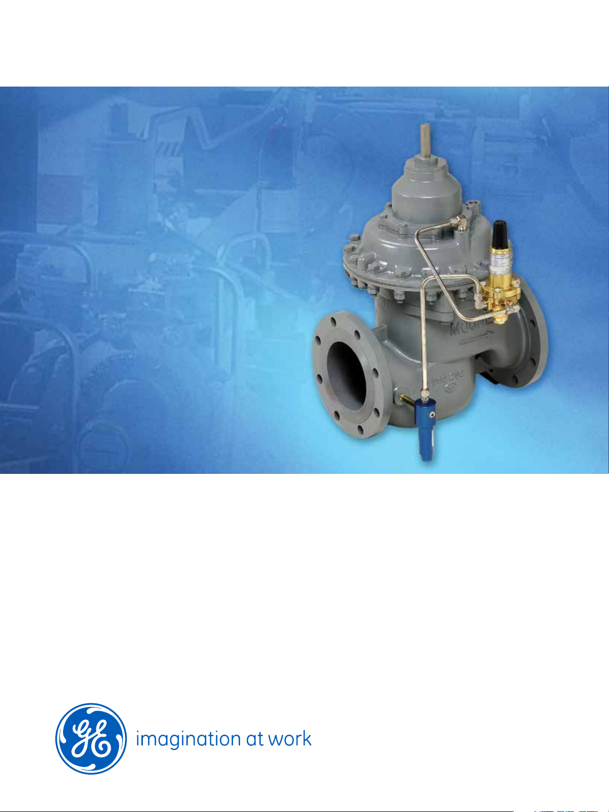
Mooney* FlowMax*
pressure reducing regulator
for natural gas pipelines
Page 2
2
Page 3
The Mooney FlowMax regulator is a pressure
reducing regulator that offers bubble tight shutoff at all pressure differentials and full capacity
at very low differential pressures. This innovative
GE Oil & Gas design compliments the Mooney
Flowgrid* regulator. The FlowMax regulator
maximizes capacity, speed of response, and
accuracy while incorporating many of the same
original maintenance and performance features
for which the Flowgrid regulator is renowned.
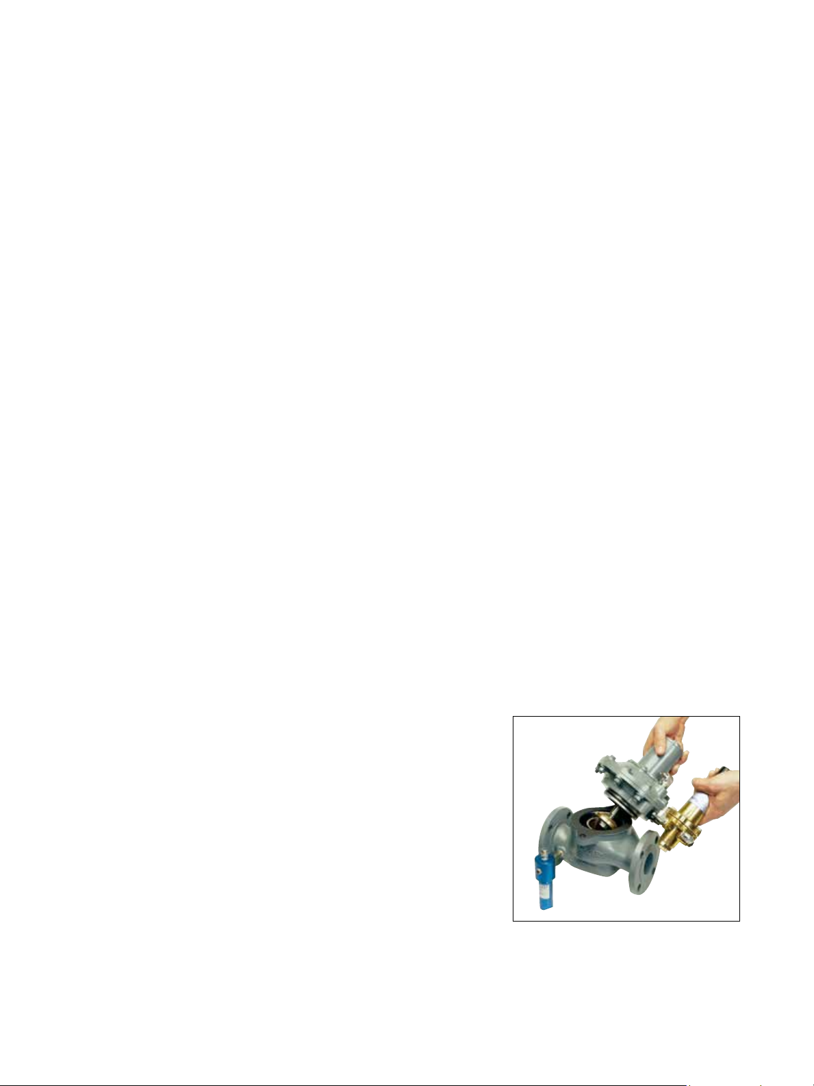
Product Features
Top-entry design for ease of maintenance
One actuator for all pressure control ranges
Oversized balanced diaphragm provides
shut off force
Full portal designs for ultra high capacity
Guiding piston
Positive bubble tight shut-off at all
pressure differentials
Control range - 5 i.w.c. to 247 psig
(12 mbar to 17 bar)
Full open differential - as low as 3 psig (0.21 bar)
Quick acting two-path pilot control system
Low-volume casing (actuator)
Lightweight and compact design
Reversible plug seal
Designed for a range of applications
District regulator
Monitor, first stage, or second stage regulator
Industrial service regulator
Boiler/burner fuel gas regulator
3
Page 4

Designed for bubble tight shut-off at all
pressures and full capacity at very low
differential pressures.
Pressure Reducing Valve
When the downstream pressure is greater than
the set point of the pilot, the pilot is closed, resulting in equal pressure above and below the main
diaphragm. With a balancing diaphragm area
slightly larger than the seat area, the resulting
closing force, along with the force of the main
spring, forces the plug against the seat.
With an increase in demand, the outlet pressure
will begin to drop and decrease the pressure
above the main diaphragm. The drop of the outlet
pressure below the pilot set point will cause the
pilot to open. As the pilot opens, pressure increases underneath the main diaphragm faster than
pressure can bleed through the internal restrictor.
The imbalance in pressure on the main diaphragm
overcomes the spring force and the additional
closing force from the balancing diaphragm,
causing the plug to rise off the seat and satisfy
the flow demand.
Once the flow demand is satisfied and the downstream pressure begins to increase, the pressure
above the main diaphragm and in the pilot sense
cavity rises.
This causes the pilot to close. The pressure below
the main diaphragm bleeds through the internal restrictor until pressure equalizes above and
below the main diaphragm. The forces of the main
spring and the over-sized balancing diaphragm
then close the plug on the seat.
Back Pressure Valve
In a back pressure relief application (BPV) the valve
functions to maintain upstream pressure at the
pilot set point. The sense line for the control pilot is
located upstream of the regulator. The extra sense
port on the actuator is plugged for BPV pilot
configuration. The action of the pilot is the reverse
of a pressure reducing pilot, such that the pilot
opens when the upstream pressure increases
above its set point. The pilot will close when the
upstream pressure is less than its set point.
Plug
BPV Pilot Sense
Pilot Supply
4
PRV Pilot Sense
Pilot Loading
for BPV
Balancing Diaphragm
Regulator Sense Line
Internal Restrictor
Inlet Pressure
Loading Pressure Outlet Pressure
Page 5

Spring Color Series 20*
Pilot
Outlet Presure
Range
White 20L 5-15 i. w. c.
(12 mbar - 37 mbar)
Brown 20L 10-40 i. w. c.
(25 mbar - 100 mbar)
Yellow 20L 1-3 psig
(0.02 bar - 0.21 bar)
Orange 20L 2-5 psig
(0.14 bar - 0.34 bar)
Gray 20L 4-8 psig
(0.28 bar - 0.55 bar)
Spring Color Series 20
Pilot
Red 20 3-12 psig
Cadmium 20 10-40 psig
Blue 20 25-90 psig
Purple 20 60-200 psig
Black 20 100-260 psig
Outlet Presure
Range
(0.21 bar - 0.83 bar)
(0.69 bar - 3 bar)
(2 bar - 6 bar)
(4 bar - 14 bar)
(7 bar - 18 bar)
Specifications
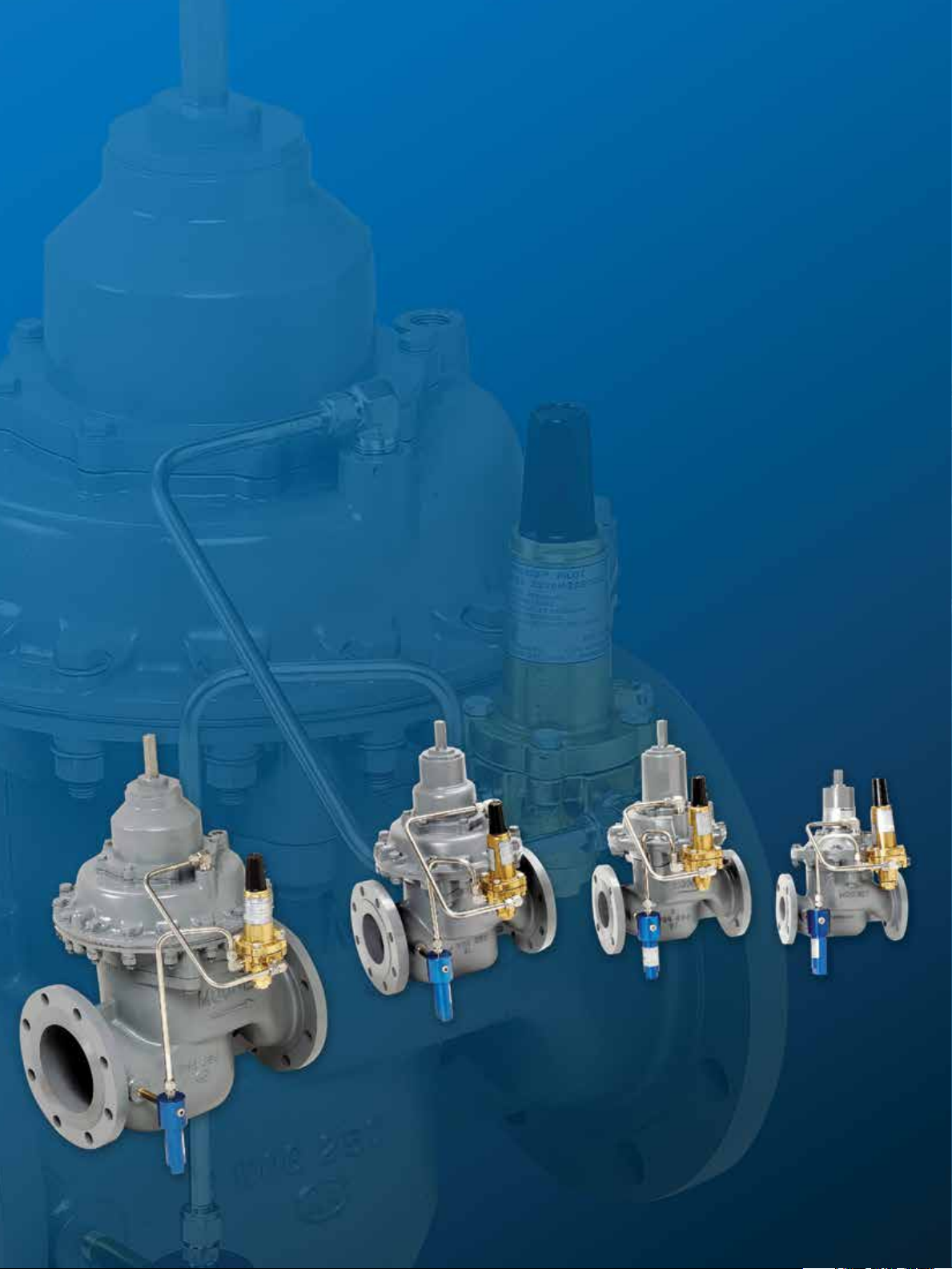
Body Size 2” (DN 50) 3” (DN 80) 4” (DN 100) 6” (DN 150)
End Connection
Minimum Differential
(fully open)
Maximum Inlet Pressure
Maximum Outlet Pressure
Maximum Casing Pressure
Outlet Pressures
Series 20 Pilot
Series 20L Pilot
Maximum Differential
Pressure
Temperature
Emergency Temperature
100% Capacity
Cg
C
1
C
v
50% Capacity
Cg
C1
C
v
Face to Face Dimensions
NPT
CL 150 RF & CL 150 FF
Weight
NPT
CL 150 RF & CL 150 FF
NPT
ANSI CL 150 RF
CL 150 FF***
3 psig (0.21 bar) 4 psig (0.28 bar) 4 psig (0.28 bar) 4 psig (0.28 bar)
250 psig (17 bar) 250 psig (17 bar) 250 psig (17 bar) 250 psig (17 bar)
250 psig (17 bar) 250 psig (17 bar) 250 psig (17 bar) 250 psig (17 bar)
250 psig (17 bar) 250 psig (17 bar) 250 psig (17 bar) 250 psig (17 bar)
3-246 psig
(0.21-17 bar)
5 i.w.c.-8 psig
(12.5 mbar-0.55 bar)
250 psid (17 bar) 250 psid (17 bar) 250 psid (17 bar) 250 psid (17 bar)
-20°F to 150°F
(-29°C to 66°C)
-40°F to 175°F
(-40°C to 79°C)
2,250
35
64
1,200
31**
39**
10.50 (267 mm)
10.00 (254 mm)
31 lbs (14 kg)
36 lbs (16 kg)
ANSI CL 150 RF
CL 150 FF***
3-246 psig
(0.21-17 bar)
5 i.w.c.-8 psig
(12.5 mbar-0.55 bar)
-20°F to 150°F
(-29°C to 66°C)
-40°F to 175°F
(-40°C to 79°C)
4,200
37
114
2,100
32**
66**
N/A
11.75 (298 mm)
N/A
59 lbs (27 kg)
ANSI CL 150 RF
CL 150 FF***
3-246 psig
(0.21-17 bar)
5 i.w.c.-8 psig
(12.5 mbar-0.55 bar)
-20°F to 150°F
(-29°C to 66°C)
-40°F to 175°F
(-40°C to 79°C)
7,500
35
212
3,800
31**
123**
N/A
13.88 (353 mm)
N/A
103 lbs (47 kg)
ANSI CL 150 RF
CL 150 FF***
3-246 psig
(0.21-17 bar)
5 i.w.c.-8 psig
(12.5 mbar-0.55 bar)
-20°F to 150°F
(-29°C to 66°C)
-40°F to 175°F
(-40°C to 79°C)
14,500
37
393
7,200
31
231
N/A
17.75 (451 mm)
N/A
190 lbs (86 kg)
** Estimated
*** CL150 FF mates with 125 FF cast iron pipe.
5
Page 6

Flow Capacity Charts
(MSCFH)
Inlet
Pressure
psig (bar)
3 (0.21) 0.25 (0.02)
5 (0.34)
10 (0.69)
15 (1.0)
25 (1.7)
30 (2.1)
40 (2.8)
50 (3.4)
Outlet
Pressure
psig (bar)
1 (0.07)
0.25 (0.02)
1 (0.07)
3 (0.21)
0.25 (0.02)
1 (0.07)
3 (0.21)
5 (0.34)
0.25 (0.02)
1 (0.07)
3 (0.21)
5 (0.34)
10 (0.69)
0.25 (0.02)
1 (0.07)
3 (0.21)
5 (0.34)
10 (0.69)
15 (1.0)
0.25 (0.02)
1 (0.07)
3 (0.21)
5 (0.34)
10 (0.69)
15 (1.0)
20 (1.4)
0.25 (0.02)
1 (0.07)
3 (0.21)
5 (0.34)
10 (0.69)
15 (1.0)
20 (1.4)
30 (2.1)
0.25 (0.02)
1 (0.07)
3 (0.21)
5 (0.34)
10 (0.69)
15 (1.0)
20 (1.4)
30 (2.1)
40 (2.8)
2”
(50 DN)3”(80 DN)4”(100 DN)6”(150 DN)
32
28
43
40
30
63
62
57
50
80
79
76
72
56
97
96
94
91
80
61
130
130
126
124
118
108
94
159
159
159
156
151
145
136
106
188
188
188
188
183
179
172
153
117
57
50
76
71
53
114
111
101
89
146
144
138
130
99
177
175
170
164
143
108
243
243
230
226
214
195
167
297
297
297
285
276
263
246
189
351
351
351
351
335
325
312
274
208
107
93
142
133
99
210
205
189
166
268
265
254
240
185
323
320
312
303
266
203
433
433
420
414
393
361
312
530
530
530
518
505
484
454
353
627
627
627
627
610
595
575
509
389
197
171
263
245
181
393
382
350
307
505
498
475
448
342
610
604
587
567
495
373
837
837
795
782
738
673
578
1025
1025
1025
984
952
908
848
651
1212
1212
1212
1212
1156
1123
1078
946
717
Inlet
Pressure
psig (bar)
60 (4.1)
70 (4.8)
80 (5.5)
100 (6.9)
Outlet
Pressure
psig (bar)
0.25 (0.02)
1 (0.07)
3 (0.21)
5 (0.34)
10 (0.69)
15 (1.0)
20 (1.4)
30 (2.1)
40 (2.8)
50 (3.4)
0.25 (0.02)
1 (0.07)
3 (0.21)
5 (0.34)
10 (0.69)
15 (1.0)
20 (1.4)
30 (2.1)
40 (2.8)
50 (3.4)
60 (4.1)
0.25 (0.02)
1 (0.07)
3 (0.21)
5 (0.34)
10 (0.69)
15 (1.0)
20 (1.4)
30 (2.1)
40 (2.8)
50 (3.4)
60 (4.1)
70 (4.8)
0.25 (0.02)
1 (0.07)
3 (0.21)
5 (0.34)
10 (0.69)
15 (1.0)
20 (1.4)
30 (2.1)
40 (2.8)
50 (3.4)
60 (4.1)
70 (4.8)
2”
(50 DN)3”(80 DN)4”(100 DN)6”(150 DN)
217
217
217
217
217
210
206
191
168
127
246
246
246
246
246
246
238
227
209
181
136
275
275
275
275
275
275
269
260
246
225
194
145
333
333
333
333
333
333
333
324
314
301
282
255
405
405
405
405
405
385
375
346
300
225
459
459
459
459
459
459
434
411
376
324
242
514
514
514
514
514
514
492
473
445
405
347
257
622
622
622
622
622
622
622
592
572
544
507
457
724
724
724
724
724
701
686
638
558
422
820
820
820
820
820
820
792
756
696
604
453
917
917
917
917
917
917
896
867
820
751
647
482
1111
1111
1111
1111
1111
1111
1111
1079
1048
1002
938
850
1399
399
1399
1399
1399
1328
1293
1193
1036
778
1586
1586
1586
1586
1586
1586
1499
1419
1298
1119
834
1773
1773
1773
1773
1773
1773
1700
1633
1536
1397
1197
887
2148
2148
2148
2148
2148
2148
2148
2044
1974
1878
1749
1576
NOTE: High differentials may result in high outlet piping velocities. Swaging up outlet piping is required.
6
Page 7

Flow Capacity Charts
(MSCFH)
Inlet
Pressure
psig (bar)
125 (8.6)
150 (10.3)
175 (12)
Outlet
Pressure
psig (bar)
0.25 (0.02)
1 (0.07)
3 (0.21)
5 (0.34)
10 (0.69)
15 (1.0)
20 (1.4)
30 (2.1)
40 (2.8)
50 (3.4)
60 (4.1)
70 (4.8)
100 (6.9)
0.25 (0.02)
1 (0.07)
3 (0.21)
5 (0.34)
10 (0.69)
15 (1.0)
20 (1.4)
30 (2.1)
40 (2.8)
50 (3.4)
60 (4.1)
70 (4.8)
100 (6.9)
125 (8.6)
0.25 (0.02)
1 (0.07)
3 (0.21)
5 (0.34)
10 (0.69)
15 (1.0)
20 (1.4)
30 (2.1)
40 (2.8)
50 (3.4)
60 (4.1)
70 (4.8)
100 (6.9)
125 (8.6)
150 (10.3)
2”
(50 DN)3”(80 DN)4”(100 DN)6”(150 DN)
406
406
406
406
406
406
406
406
394
385
372
356
268
478
478
478
478
478
478
478
478
478
464
455
444
386
295
551
551
551
551
551
551
551
551
551
551
535
526
484
423
320
758
758
758
758
758
758
758
758
721
701
675
642
477
893
893
893
893
893
893
893
893
893
849
930
805
693
525
1029
1029
1029
1029
1029
1029
1029
1029
1029
1029
978
958
873
757
568
1353
1353
1353
1353
1353
1353
1353
1353
1314
1283
1242
1186
893
1595
1595
1595
1595
1595
1595
1595
1595
1595
1548
1518
1479
1287
983
1837
1837
1837
1837
1837
1837
1837
1837
1837
1837
1783
1752
1613
1410
1065
2616
2616
2616
2616
2616
2616
2616
2616
2488
2419
2330
2217
1648
3084
3084
3084
3084
3084
3084
3084
2932
2864
2780
2392
1812
3552
3552
3552
3552
3552
3376
3309
3014
2615
1961
Inlet
Pressure
psig (bar)
200 (14)
—
—
225 (16)
—
—
—
—
—
250 (17)
Outlet
Pressure
psig (bar)
0.25 (0.02)
1 (0.07)
3 (0.21)
5 (0.34)
10 (0.69)
15 (1.0)
20 (1.4)
30 (2.1)
40 (2.8)
50 (3.4)
60 (4.1)
70 (4.8)
100 (6.9)
125 (8.6)
150 (10.3)
175 (12)
3 (0.21)
5 (0.34)
10 (0.69)
15 (1.0)
20 (1.4)
30 (2.1)
40 (2.8)
50 (3.4)
60 (4.1)
70 (4.8)
100 (6.9)
125 (8.6)
150 (10.3)
175 (12)
200 (14)
3 (0.21)
5 (0.34)
10 (0.69)
15 (1.0)
20 (1.4)
30 (2.1)
40 (2.8)
50 (3.4)
60 (4.1)
70 (4.8)
100 (6.9)
125 (8.6)
150 (10.3)
175 (12)
200 (14)
225 (16)
2”
(50 DN)3”(80 DN)4”(100 DN)6”(150 DN)
2079
2079
2079
2079
2079
2079
2079
2079
2079
2017
1908
1757
1523
1142
2321
2321
2321
2321
2321
2321
2321
2188
2069
1892
1629
1214
2563
2563
2563
2563
2563
2563
2563
2563
2458
2361
2220
2019
1729
1282
—
—
4020
4020
4020
4020
4020
4020
4020
3820
3582
3276
2821
2010
—
—
—
4488
4488
4488
4488
4488
4488
4488
4120
3872
3520
3013
2232
—
—
4956
4956
4956
4956
4956
4956
4956
4642
4433
4145
3749
3194
2355
624
624
624
624
624
624
624
624
624
624
624
605
573
527
457
343
696
696
696
696
696
696
696
696
696
696
656
621
568
489
364
769
769
769
769
769
769
769
769
769
769
737
708
666
606
519
385
1164
1164
1164
1164
1164
1164
1164
1164
1164
1164
1106
1038
949
817
609
1300
1300
1300
1300
1300
1300
1300
1300
1300
1300
1194
1122
1019
873
646
1435
1435
1435
1435
1435
1435
1435
1435
1345
1345
1284
1201
1086
925
682
—
—
—
—
—
—
—
—
—
—
—
—
NOTE: High differentials may result in high outlet piping velocities. Swagging up outlet piping is required.
7
Page 8

GE Oil & Gas
2822 S. 1030 West
Salt Lake City, UT 84119
T: +1 801.487.2225
F: +1 801.487.2587
E: mooney.inquiries@ge.com
Visit us online at:www.ge.com/energy
©2014 General Electric Company
All Rights Reserved
*Trademark of General Electric Company
GEA19188_Mooney FlowMax Regulator
6.14
 Loading...