

Page 1
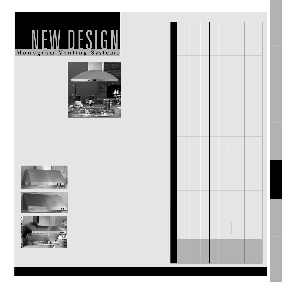
New 42" CFM
Dual Blower
Island Hood
This 42" stainless steel
island hood has a fourspeed dual blower fan
that operates at a
maximum venting power
of 1080 CFM. Use duct
cover accessories to
reach ceiling heights up to 10 ft.
The New Line of Professional
Hoods Offer Three Distinctly
Different Styles
Choose straight sided, taper-sided or the dramatic
Restaurant-Style Hood.
ZV48TSFSS
ZV36T ZV36S ZV36R ZVB36
ZV48T ZV48S ZV48R
Included Remote Blower
A complete line of Monogram hoods.
and Ranges
Products
Refrigeration
Professional
Cooking Products
Warming Drawers
Ovens, Microwave
Cooking Surfaces
ZV48SSFSS
Included Required 9' or 10' 6" and 12" Duct Covers - Stackable Options
ZV48RSFSS
Optional Optional
Included
10' Ceiling 10' to 14' Must Order Duct Cover
Duct Cover Duct Cover Separately Optional
These new Monogram® Professional Hoods are available
in 48", 36" and 30" widths. All with four speed blower fan,
halogen lights and infrared warming lights.
92 93
Platform Wall Mounted Island Hoods Professional Hoods Downdraft
Model ZV750 ZV950 ZV850 ZV1050 ZV30T ZV30S ZV30R ZVB30
Style European European European European Taper Straight Restaurant Integrated
Width 36" 36" 36" 42" 30", 36", 48" 30", 36", 48" 30", 36", 48" 30", 36"
Blower Rating 360 700 360 1080 30", 36"-640 30", 36"-640 30",36"-640 500
(CFM) 48"-1200 48"-1200 48"-1200
Recirculating 8', 9', 10' No 8', 9', 10' No No No No No
Option Options Options
Vented 8', 9' 8', 9' 10' 8', 9' or 10' 8' Duct Cover Indoor, Outdoor
Options
Duct Cover Duct Cover Duct Cover Duct Cover
Monogram All All 30" & 36" All All All
Installation Non-Pro Cooktops Non-Pro 30" & 36" All Monogram Cooktops and Ranges Non-Pro
Combinations Cooktops and Ranges Cooktops Cooktops Cooktops
Venting Systems
Dishwashers, Chef’s
Washers, Compactors
Outdoor
Cooking Centers
Page 2
Professional Hood Features
18"
20"
25"
29-15/16"
12"
Taper-Sided ZV48TSFSS ZV36TSFSS ZV30TSFSS
Straight-Sided ZV48SSFSS ZV36SSFSS ZV30SSFSS
Features
Variable Speed Fan Control 4-Speed 4-Speed 4-Speed
Internal Blower Rating 1200 CFM 640 CFM 640 CFM
Halogen Lamps 3 2 2
Variable Light Control 4-Level 4-Level 4-Level
Infrared Warming Lights 2 1 1
Removable Stainless Steel Filters 3 2 2
Grease Filter Trays 3 2 2
Professional Design Knobs • • •
Blower Indicator Light • • •
Stainless Steel Utensil Racks • • •
Exhaust Options
10" Round Exhaust Duct • • •
8" Round Exhaust Duct Option Option Option
Exhaust Damper • • •
Accessories
6" Stackable Duct Covers ZX48DC6 ZX36DC6 ZX36DC6
12" Stackable Duct Covers ZX48DC12 ZX36DC12 ZX36DC12
General Features
Overall Dimensions 47-15/16 x 35-15/16 x 29-15/16 x
(WxHxD in inches) 18 x 25 18 x 25 18 x 25
Amps @ 120VAC 12.4 6.4 6.4
Approx. Shipping Weight (lbs.) 130 110 100
Warranty Information
Full One-year warranty, parts and labor.
See written warranty for details.
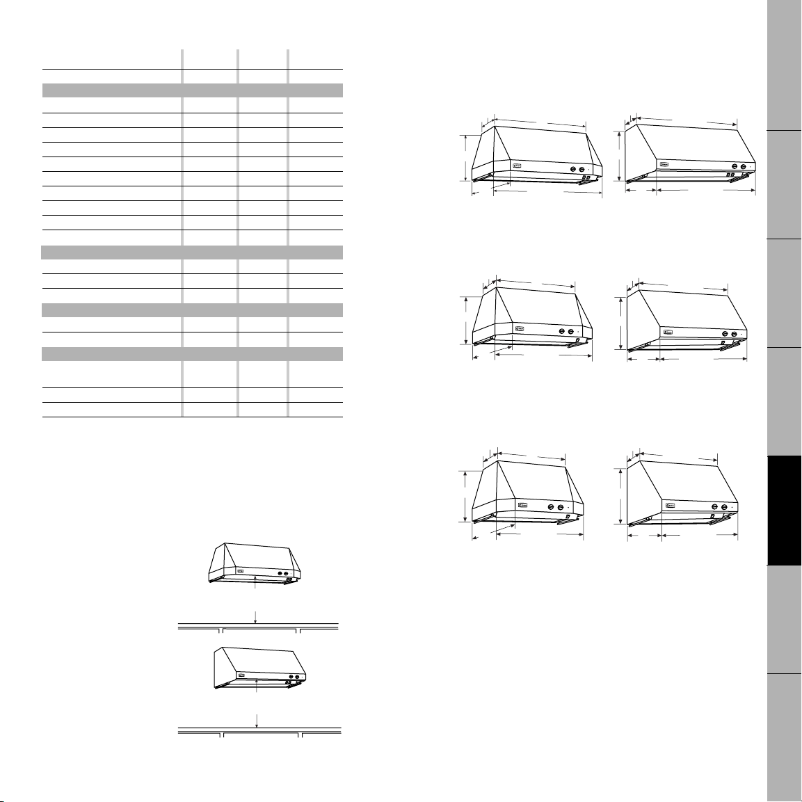
Professional Hood Dimensions
Select a taper-sided or straight sided hood to match the
width of cooktop or range.
48" Wide Models
18"
18"
12"
12"
12"
25"
25"
47-15/16"
47-15/16"
35-15/16"
35-15/16"
29-15/16"
12"
18"
25"
Diagram 3 Diagram 4
ZV48TSFSS with Tapered Sides ZV48SSFSS with Straight Sides
36" Wide Models
12"
18"
25"
Diagram 5 Diagram 6
ZV36TSFSS with Tapered Sides ZV36SSFSS with Straight Sides
30" Wide Models
38"
47-15/16"
26"
35-15/16"
Products
Refrigeration
Professional
Cooking Products
Warming Drawers
Ovens, Microwave
Cooking Surfaces
Installation Height Requirements
• Install these vent hoods 30" Min. to 36" Max above the
cooking surface of any professional style range or cooktop.
• These hoods may be installed 24" min. above a gas or electric
drop-in style cooktop.
Models with
Tapered Sides
ZV48TSFSS
ZV36TSFSS
ZV30TSFSS
Models with
Straight Sides
ZV48SSFSS
ZV36SSFSS
ZV30SSFSS
Note: Exact installation height
may be determined by use of
one or more duct covers.
See Accessory Duct Covers, page 99.
94 95
Diagram 1
Diagram 2
30" MIN.
36" MAX.
30" MIN.
36" MAX.
Diagram 7 Diagram 8
ZV30TSFSS with Tapered Sides ZV30SSFSS with Straight Sides
Blower outlet is 8-1/8" x 8".
Includes a transition for 10" round.
18"
25"
29-15/16"
Venting Systems
Dishwashers, Chef’s
Washers, Compactors
Outdoor
Cooking Centers
Page 3
Restaurant-Style Professional Hoods
47-15/16"
47-15/16"
10"
25"
12"
22-1/2"
12"
22-1/2"
29-15/16"
29-15/16"
25"
10"
ZV48RSFSS ZV36RSFSS ZV30RSFSS
Features
Variable Speed Fan Control 4-Speed 4-Speed 4-Speed
Internal Blower Rating 1200 CFM 640 CFM 640 CFM
Halogen Lamps 3 2 2
Variable Light Control 4-Level 4-Level 4-Level
Infrared Warming Lights 2 1 1
Removable Stainless Steel Filters 3 2 2
Grease Filter Trays 1 1 1
Stainless Steel Backsplash •••
Stainless Steel Warming Shelf •••
Professional Design Knobs •••
Blower Indicator Light •••
Stainless Steel Utensil Racks •••
Exhaust Options
10" Round Exhaust Duct •••
8" Round Exhaust Duct Option Option Option
Exhaust Damper •••
Accessories
6" Stackable Duct Covers ZX48DC6 ZX36DC6 ZX36DC6
12" Stackable Duct Covers ZX48DC12 ZX36DC12 ZX36DC12
General Features
Overall Dimensions 47-15/16 x 35-15/16 x 29-15/16 x
(WxHxD in inches) 22-1/2 x 25 22-1/2 x 25 22-1/2 x 25
Amps @ 120VAC 12.5 6.5 6.5
Approx. Shipping Weight (lbs.) 130 110 100
Warranty Information:
Full One-Year Warranty.
See written warranty for details.
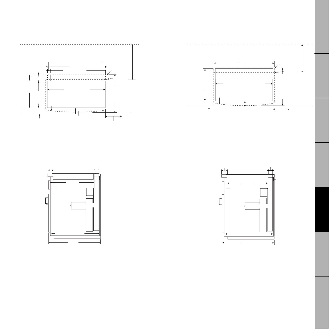
Installation Height Requirements
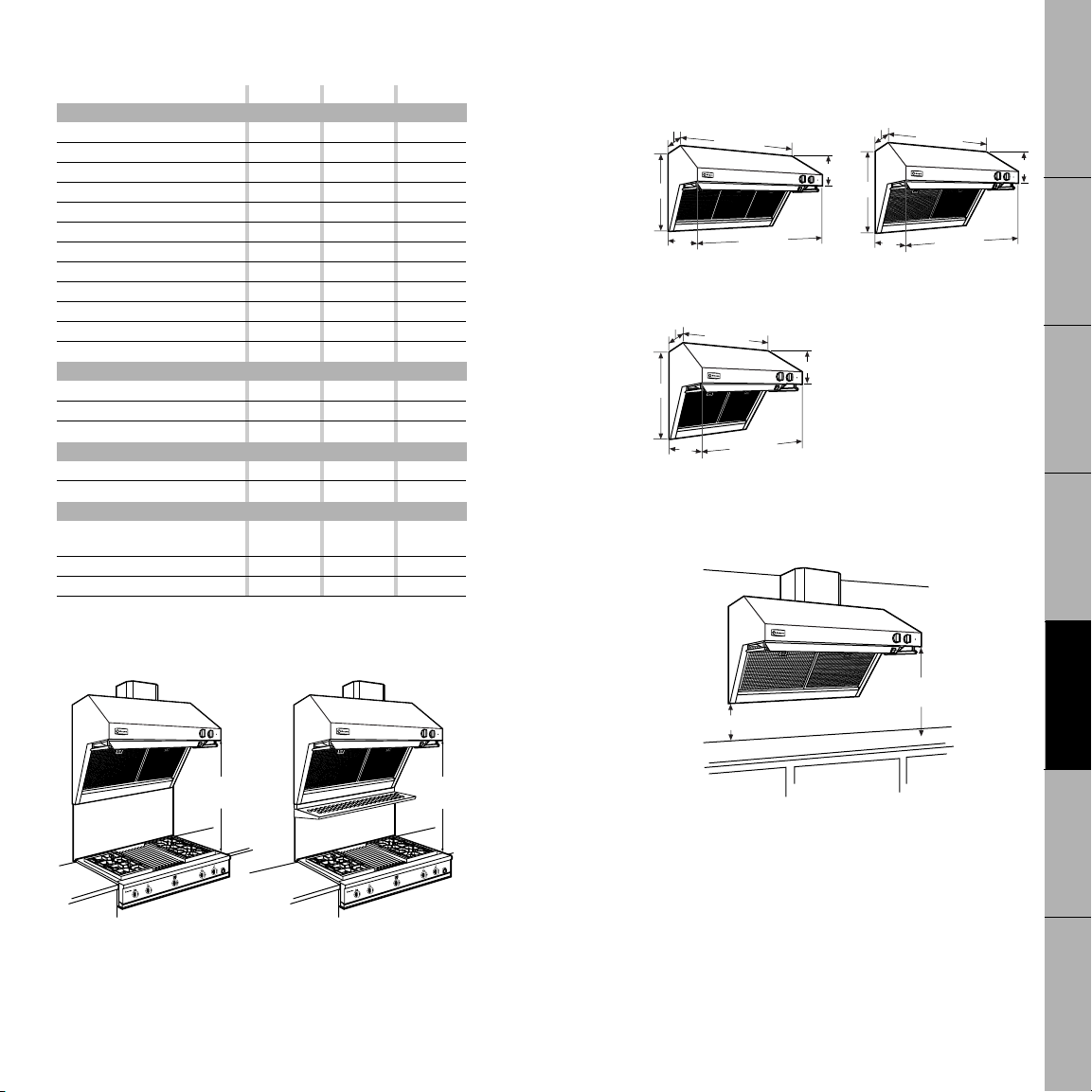
Restaurant-Style Hood Dimensions
Select a hood to match the width of cooktop or range.
48" Wide Model 36" Wide Model
Diagram 11 Diagram 12
ZV48RSFSS ZV36RSFSS
30" Wide Model
Diagram 13
ZV30RSFSS
12"
35-15/16"
22-1/2"
35-15/16"
25"
Blower outlet is 8-1/8" x 8"
Includes a transition for 10" round.
Determine Installation Height
Installation
Height
Dim. A
Refrigeration
10"
Professional
Ovens, Microwave
Products
Cooking Products
Warming Drawers
Cooking Surfaces
Venting Systems
30" Min.
36" Max.
32" Min.
38" Max.
Diagram 14
Determine bottom of hood location (Dimension A) by
subtracting 12-1/2" from the desired installation height.
IMPORTANT:
“Using Duct Cover Accessories”, page 99. Exact installation height may be
Diagram 9
Installation without Warming Shelf
Install these hoods 30" min. to 36"
max. above the cooking surface of
any professional style range or
cooktop.
These hoods may be installed 24" min. above a gas or electric drop-in style
cooktop.
96 97
Installation with Warming Shelf
Install these vent hoods 32" min. to 38"
max. above any type cooking surface
when warming shelf if used.
Diagram 10
determined by use of one or more duct covers.
If you are installing the hood with duct covers, be sure to read
Dishwashers, Chef’s
Washers, Compactors
Outdoor
Cooking Centers
Page 4
Advance Planning for
6" Duct Cover
12" Duct Cover
Ceiling Height
A
C
B
10"
Hood
Height
All Professional Vent Hoods
• Select a straight, tapered or restaurant-style hood to match
the width of the range or cooktop.
• All models can be installed onto a wall or beneath a soffit.
Duct covers are available to conceal the ductwork (at extra
cost). Duct covers are available in 6" to 12" heights. They can
be stacked in various combinations to reach ceiling heights.
• To avoid unsightly gaps, plan the hood installation height
with consideration to duct cover use. See the opposite page
to determine the need for one or more 6" or 12" duct covers.
Adequate Structural Support
• All Professional Hoods weigh over 100 pounds. Therefore,
adequate structural support must be provided. Hoods must
be secured to vertical studs or to studs in the soffit.
• It is strongly recommended that the vent hood and duct
cover(s) if used, be on site before final framing and wall
finishing. This will help to accurately locate the ductwork and
electrical service.
• Final installation will be much easier if the hood is installed
before the range or cooktop below.
Accessory Duct Covers
• Decorative duct covers are designed to complement all
Professional Hoods. Available in 6" and 12" heights. Duct
covers may be stacked, in various combinations to conceal
the ductwork running from the top of the hood.
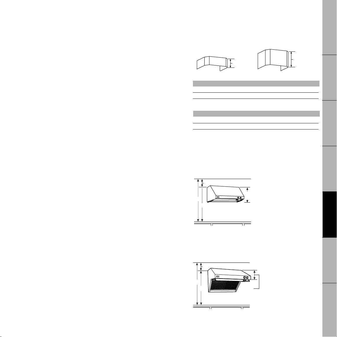
Diagram 15
6" Duct Covers
Hoods 6" Duct Cover Dimensions
ZV48 ZX48DC6 6"H x 19-11/16"W x 11-7/8"D
ZV36, ZV30 ZX36DC6 6"H x 15-3/4"W x 11-7/8"D
12" Duct Covers
Hoods 12" Duct Cover Dimensions
ZV48 ZX48DC12 12"H x 19-11/16"W x 11-7/8"D
ZV36, ZV30 ZX36DC12 12"H x 15-3/4"W x 11-7/8"D
Using Duct Cover Accessories
Use the following formulas to calculate the need for one or
more duct covers and to ensure a trouble free installation.
Products
Refrigeration
Professional
Cooking Products
Warming Drawers
Ovens, Microwave
Ductwork Planning
• These vent hoods are equipped for 10" round ductwork. In
most instances they may be transitioned to 8" round using
locally supplied transition pieces.
• Determine the exact location of the vent hood.
• Plan the route for venting exhaust to the outdoors.
• Always use the shortest and straightest route possible.
• For satisfactory performance, duct run should not exceed
150 feet equivalent length for any duct configuration. Refer
to the Duct Fittings chart in the installation instructions.
• Install a wall cap or roof cap with damper at the exterior
opening. Order the wall or roof cap and any transition
needed in advance.
Refer to Installation Instructions for details
Pub. No. 49-80151 for Straight and Taper-Sided Professional Hoods
Pub. No. 49-80152 for Restaurant-Style Professional Hoods
98
Straight or Taper-Sided Hoods
Ceiling Height
B
18" Hood
A
C
Note: Dimension C should be between 40" and 46" (for a 30" to 36" installation
height). Raise or lower the hood installation height to allow use of one or
more 6" and 12" duct covers.
A - B = C
A = Countertop to ceiling height.
B = Gap at the top of the hood to
Height
the ceiling.
C = Hood installation height, Plus
18" hood height.
Diagram 16
Restaurant-Style Hoods
A - B = C
A = Countertop to ceiling height.
B = Gap at the top of the hood to
the ceiling.
C = Hood installation height, Plus
10" hood height.
Diagram 17
Note: Dimension C should be between 48" and 54" (for a 30" to 36" installation
height). Raise or lower the hood installation height to allow use of one or
more 6" and 12" duct covers.
99
Cooking Surfaces
Venting Systems
Dishwashers, Chef’s
Washers, Compactors
Outdoor
Cooking Centers
Page 5
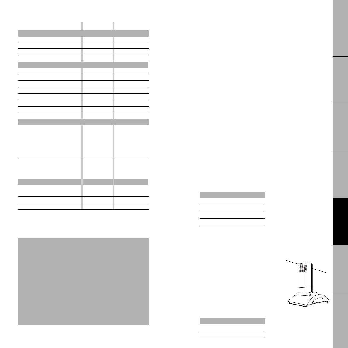
36" Stainless Steel Wall Mount Hoods
Description ZV750SY ZV950SDSS
Features 36" Hood 36" Hood
Electronic Touch Controls ••
Internal Blower Rating 360 CFM 700 CFM
Blowers 1 2
Boost Mode ••
Convenience
Halogen Lamps 4 4
Variable Light Control 6 6
Removable Filters 3 3
Filter Cleaning Reminder ••
Blower Speeds 4 4
Time Delay Shut-Off ••
Utensil Racks ••
Round Duct 6" 8"
Accessories
Vented Accesssories:
8 ft. duct cover Included Included
9 ft. duct cover Included Included
10 ft. duct cover ZX10SY Included
10 ft. to 14 ft. duct cover – ZX14SDSS
Recirculating Accesssories:
To 9 ft. duct cover ZXR758 N/A
To 10 ft. duct cover ZXR7510 N/A
General Features
Overall Dimensions 34-5/8 x 35-5/8 x
(WxHxD in inches) 8-1/2 x 21-5/8 10 x 25
Amps @ 120V 2.5 4.3
Approx. Shipping Wt. (lbs.) 81 110
Warranty Information
Full One-year warranty, parts and labor.
See written warranty for details.
Additional Features
• Supplied with decorative stainless steel duct covers that
conceal the ductwork running from the top of the hood to
the ceiling.
• The fan can be set for automatic shut-off after 5, 10 or 20
minutes of operation.
• Four halogen lights illuminate the cooking surface with six
light levels, including a low light/night light setting.
• Three removable filters are dishwasher safe. An indicator
light signals when the filter needs cleaning.
Advance Planning
• Installation height must be determined in advance.
Accessories for height adjustment should be ordered with the
vent hood and be on site at the time of installation.
• A mounting template is provided with the installation
instructions to help accurately position the hood above the
cooking surface and to locate the mounting brackets.
• This ZV950 hood must use 8" round duct with a maximum
equivalent duct length of 100 ft. It can transition to 3-1/4" x
12" duct with a maximum equivalent duct length of 75 ft.
• Duct covers for ceiling heights of 10 ft. or more are available
for the ZV950.
• The ZV750 hood must use 6" round duct with a maximum
equivalent duct length of 100 ft.
DUCT COVERS FOR
VENTED INSTALLATIONS
Ceiling ZV750 ZV950
8 ft. Included Included
Up to 9 ft. Included Included
Up to 10 ft ZX10SY Included
10 ft. to 14 ft. – ZX14SDSS
Products
Refrigeration
Professional
Cooking Products
Warming Drawers
Ovens, Microwave
Cooking Surfaces
ZV750 Features
• 4-speed blower fan operates at a maximum venting power
of 360 CFM.
• ZX10SY Accessory duct cover available to reach 10 ft.
ceiling heights.
• Trim kits are available for recirculating operation.
ZV950 Features
• High performance, 4-speed dual blower fan operates at a
maximum venting power of 700 CFM.
• ZX14SDSS Accessory duct cover available to reach 10 ft. to
14 ft. ceiling heights, for ZV950 only.
100
ZV750 Recirculating Installation
The ZV750 hood is designed to be vented to the outside,
but can easily be converted for recirculating operation.
These kits provide charcoal filters
which fit behind the standard grease
filters, an air deflector that fits above
the exhaust outlet and a section of
vented decorative duct cover to
complete the installation.
Recirculating kits are available
for installation with 8 ft., 9 ft.,
and 10 ft. ceiling heights.
RECIRCULATING INSTALLATIONS
Ceiling ZV750 ZV950
Up to 9 ft. ZXR758 N/A
Up to 10 ft ZXR7510 N/A
Diagram 18
101
Venting Systems
Dishwashers, Chef’s
Washers, Compactors
Outdoor
Cooking Centers
Page 6
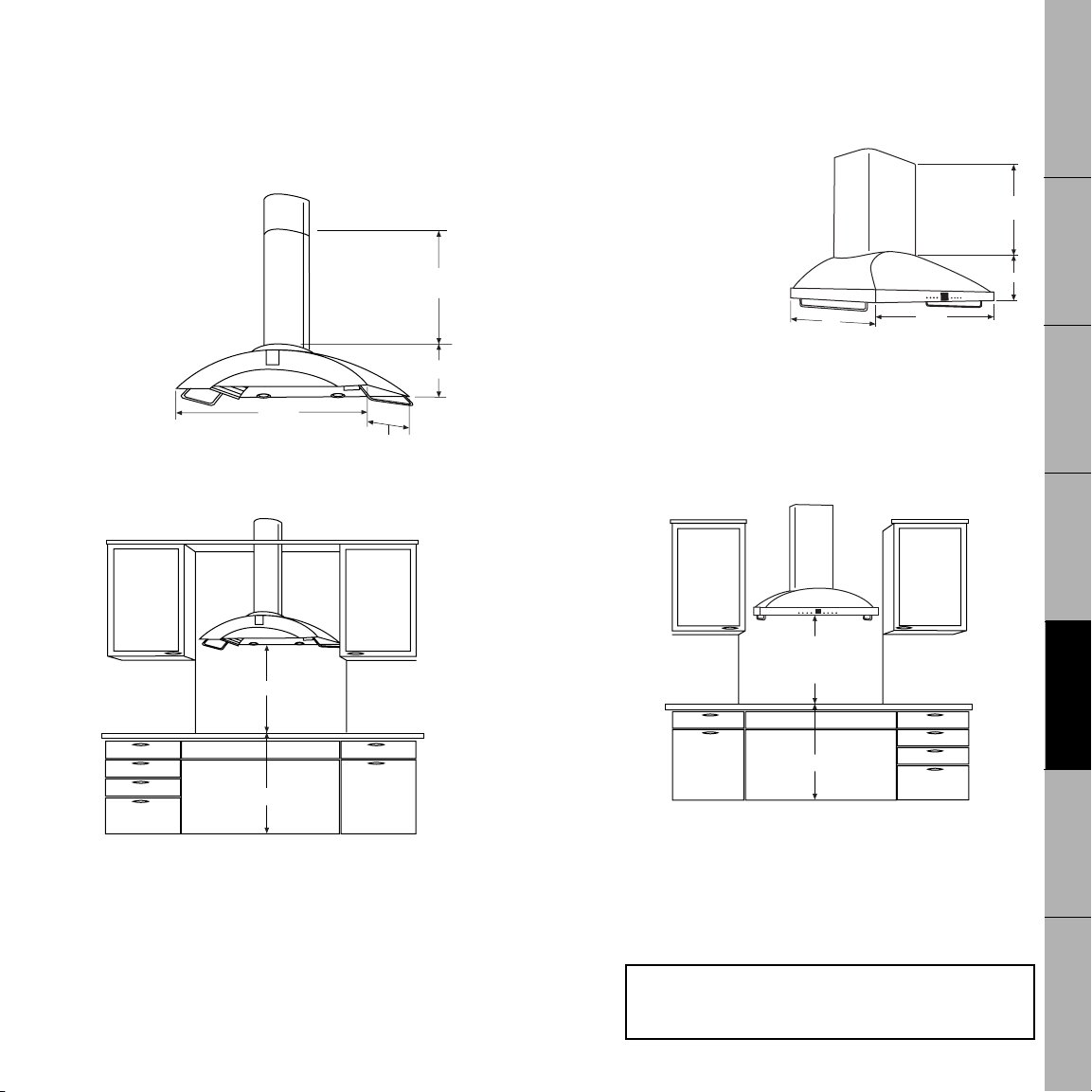
36" European Style Wall-Mount Hood
Cutout Dimensions and Clearances
This Stainless Steel Hood can be installed over any Monogram cooktop (except Professional Models).
This vent hood with duct cover is sized to fit 8 ft. to 9 ft.
ceilings. ZX10SY accessory can be ordered to reach up to
10 ft. ceiling.
Model ZV750SY
* 26-1/4" for 8 ft. ceiling
38-1/4" for 9 ft. ceiling
With Accessory ZX10SY
Duct Cover: 38-1/4" to 50-1/4"
for 9 ft. to 10 ft. ceiling.
Diagram 21
34-5/8"
21-5/8"
*Height
to Ceiling
8-1/4"
36" Dual Blower Vent Hood
Cutout Dimensions and Clearances
This stainless Steel hood can be installed over any Monogram
cooktop, including the Professional 36" cooktop and 30" or
36" range.
Model ZV950SDSS
* 24-1/2" for 8 ft. ceiling.
* 36-1/2" for 9 ft. ceiling.
* 36" to 44" for 9 ft. to 10 ft. ceiling.
(for ceilings between 9’6" and 10 ft.
mount hood 30" above cooktop)
Diagram 19
Note: The supplied 2-piece duct cover is adjustable to fit 8 ft. to 10 ft.
ceilings. For ceiling heights greater than 10 ft. and up to 14 ft., order
ZX14SDSS stainless steel duct cover accessory.
25"
35-5/8"
The vent hood must be installed 24" min. and 30" max.
above the cooking surface. The hood installation height,
from the cooking surface to the bottom of the hood,
depends upon ceiling height.
*Height
to Ceiling
10"
Products
Refrigeration
Professional
Cooking Products
Warming Drawers
Ovens, Microwave
Cooking Surfaces
*25-1/2" Recommended
36" Min.
Diagram 22
The vent hood must be installed 24" min. and 30" max.
above the cooking surface. 25-1/2" is recommended to
insure that the duct cover meets the ceiling. The cooking
surface should be at least 36" above the floor.
Refer to Installation Instructions for details
Pub. No. 49-80095 for ZV950SDSS
Pub. No. 49-8990 for ZV750SY
Pub. No. 49-80046, for ZXR758, ZXR7510
102
Installation
Height Depending
on Ceiling Height
36" Min.
Diagram 20
Cooking surface to bottom of hood should be:
• 25-1/2" max. for 8 ft. ceiling height.
• 25-1/2" to 30" for 9 ft. ceiling height.
• 30" min. for 10 ft. ceiling height.
Plan the installation height carefully to avoid unsightly gaps
above the hood.
Installation with 36" Professional Cooktop or Range
Install the hood 30" min. above the cooking surface. See
installation instructions for details.
103
Venting Systems
Dishwashers, Chef’s
Washers, Compactors
Outdoor
Cooking Centers
Page 7
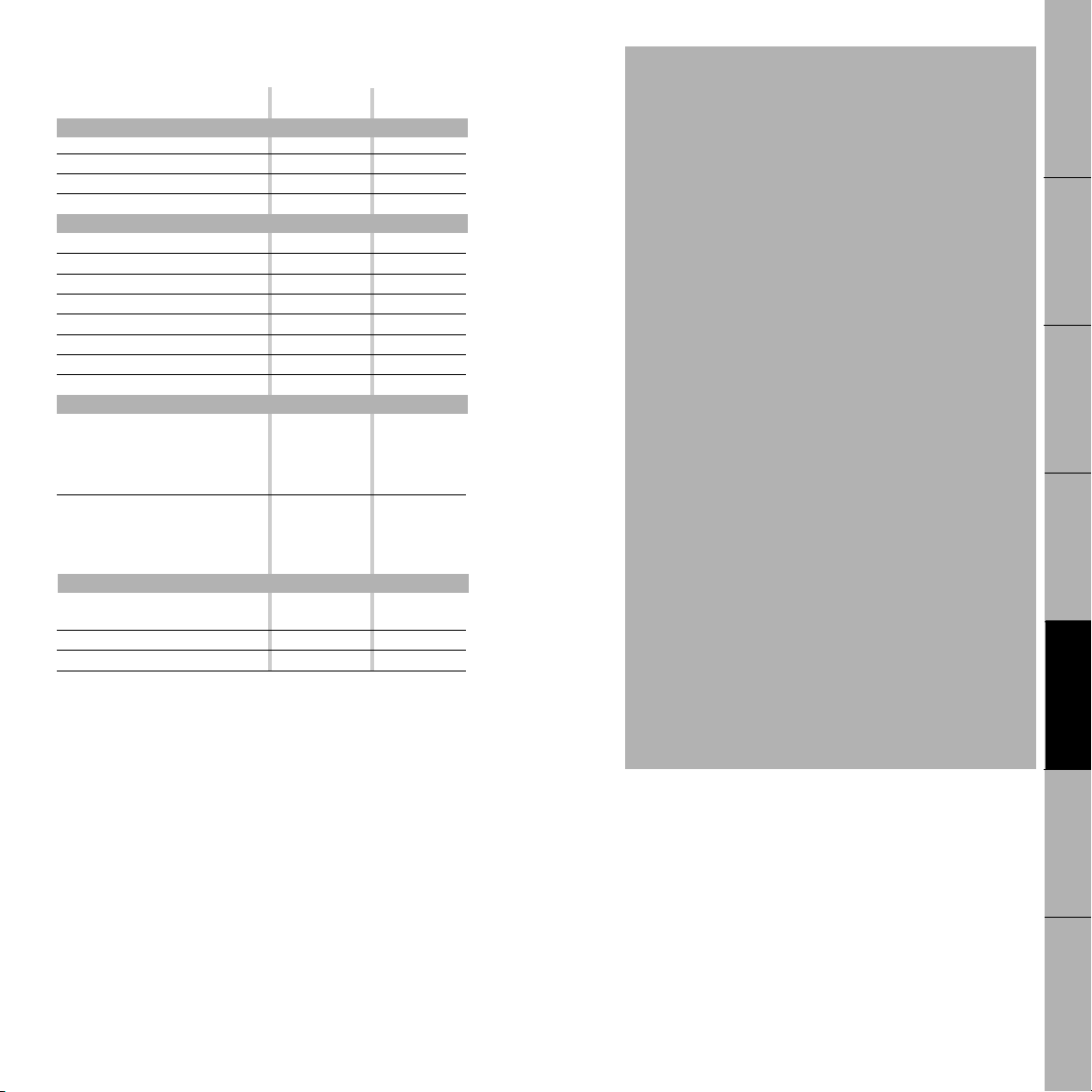
36" Island Vent Hood Features
Description 36" Island Hood 42" Island Hood
Features
Electronic Touch Controls ••
Internal Blower Rating 360 CFM 1080 CFM
Blowers 1 2
Boost Mode ••
Convenience
Halogen Lamps 4 4
Variable Light Control 6-Level 6-Level
Removable Filters 3 4
Filter Cleaning Reminder ••
Utensil Racks ••
Fan Control 4-Speed 4-Speed
Time Delay Shut-Off ••
Round Duct 6" 8"
Accessories
Vented Required Accessories:
8 ft. support/duct cover ZX858 Supplied
9 ft. support/duct cover ZX859 ZV1059SFSS
10 ft. support/duct cover ZX8510 ZV10510SFSS
Recirculating Required Accessories:
8 ft. support/duct cover ZXR858 N/A
9 ft. support/duct cover ZXR859 N/A
10 ft. support/duct cover ZXR8510 N/A
General Features
Dimensions 35-3/8 x 8-1/4 42 x 10
(WxHxD in inches) x 27-1/2 x 31-1/2
Amps @ 120V 2.5 8
Approx. Shipping Weight 81 lbs 150 lbs
Warranty Information
Full One-year warranty
See written warranty for details.
ZV850SB ZV1050SFSS
ZV850 Island Hood Features
• 4-Speed blower fan operates at a maximum venting power
of 360 CFM.
• This hood is designed to be vented to the outside but can
easily be converted for recirculating operation using an
accessory kit.
• Installation height must be determined in advance. Duct
cover accessories for 8 to 10 ft. ceiling heights are
required. One accessory must be ordered with the vent
hood and be on site at the time of installation.
• This hood must use 6" round duct with a maximum
equivalent duct length of 100 ft.
ZV1050 Island Hood Features
• High performance, 4-speed dual blower fan operates at a
maximum venting power of 1080 CFM.
• This hood must be vented to the outdoors.
• A decorative duct cover for 8 ft ceiling height (fits 7’11" to
8’1" ceiling) is supplied with the hood. Accessory duct
covers are available (at extra cost) for 9 ft. and 10 ft.
ceiling heights.
• This hood must use 8" round duct with a maximum
equivalent duct length of 100 ft.
Additional Features
• The fan can be set for automatic shut-off after 5, 10 or 20
minutes of operation.
• Four halogen lights illuminate the cooking surface with six
light levels, including a low light/night setting.
• Removable filters are dishwasher safe. An indicator light
signals when the filter needs cleaning.
• Mounting templates are provided with each installation
instruction book to help accurately position the hood on
the ceiling and above the cooking surface.
Products
Refrigeration
Professional
Cooking Products
Warming Drawers
Ovens, Microwave
Cooking Surfaces
Venting Systems
Refer to Installation Instructions for details
Pub. No. 49-8970, for ZV850 Island Hood
Pub. No. 49-80045, for ZXR858, ZXR858 and ZXR7510
Pub. No. 49-80153, for ZV1050 Island Hood
104
105
Dishwashers, Chef’s
Washers, Compactors
Outdoor
Cooking Centers
Page 8
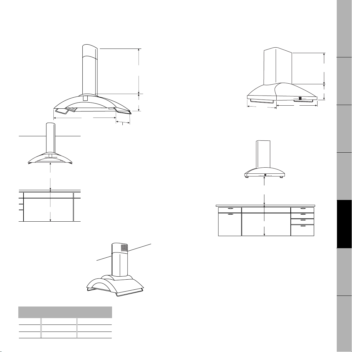
36" Island Hood Dimensions
This stainless steel hood can be installed over any
Monogram cooktop (except Professional Models.)
Accessories to meet correct ceiling heights are required.
* 26-1/4" for 8 ft. ceiling
Using ZX858 Accessory
38-1/4" for 9 ft. ceiling
Using ZX859 Accessory
50-1/8" for 10 ft. ceiling
Using ZX8510 Accessory
Model ZV850SB
Diagram 23
*25-1/2" Recommended
35-3/8"
The vent hood must be
installed 24" min. and 30"
max. above the cooking
surface. 25-1/2" is
recommended to insure
that the duct cover meets
the ceiling. The cooking
surface should be at least
36" above the floor.
27-1/2"
*Height
to Ceiling
8-1/4"
42" Island Hood Dimensions
This stainless steel hood is designed for vented ceiling
mounted installations. It can be installed over any
Monogram cooktop or range, including Professional
models.
* 20" to an 8 ft. ceiling.
Using supplied duct cover
32" for 9 ft. ceiling
Using ZX1059SFSS
Accessory
44" for 10 ft. ceiling
Using ZX10510SFSS
Accessory
Model ZV1050SFSS
31-1/2"
Diagram 26
42"
This vent hood is supplied with a decorative duct cover to
reach 8 ft. ceiling height, or between 7'11" and 8'1".
*30"
Recommended
*Height
to Ceiling
10"
Products
Refrigeration
Professional
Cooking Products
Warming Drawers
Ovens, Microwave
Cooking Surfaces
36" Min.
Diagram 24
Recirculating Installation
This hood is designed to be vented to the outside, but can
easily be converted for
recirculating operation.
Recirculating kits include
charcoal filters, an air deflector
and a section of vented
decorative duct cover to
complete the installation.
Recirculating kits are available
for installation with 8 ft., 9 ft.,
and 10 ft. ceiling heights.
CEILING VENTED RECIRCULATING
HEIGHT INSTALLATION INSTALLATION
8 ft. ZX858 ZXR858
9 ft. ZX859 ZXR859
10 ft ZX8510 ZXR8510
106
Diagram 25
IMPORTANT: One
kit must be ordered
for either type
of installation
(not both).
36" Min.
Diagram 27
* 9 ft. to 10 ft. ceilings may be 25-1/2" to 30" clearance.
*The distance between the cooking surface and the bottom of
the hood must be at least 25-1/2". The 30" recommended
installation height, above the standard 36" countertop will
insure duct cover fit to the ceiling. For 9 ft. and 10 ft. ceiling
heights, the hood may be lowered to 25-1/2" over the
cooking surface.
• When installing the Island Hood above a Monogram
Professional Range or Cooktop, installation clearance must
be at least 30".
IMPORTANT: Clearances may vary due to type of cooking product and local
codes. Check with local inspectors to be sure standard is applicable.
107
Venting Systems
Dishwashers, Chef’s
Washers, Compactors
Outdoor
Cooking Centers
Page 9
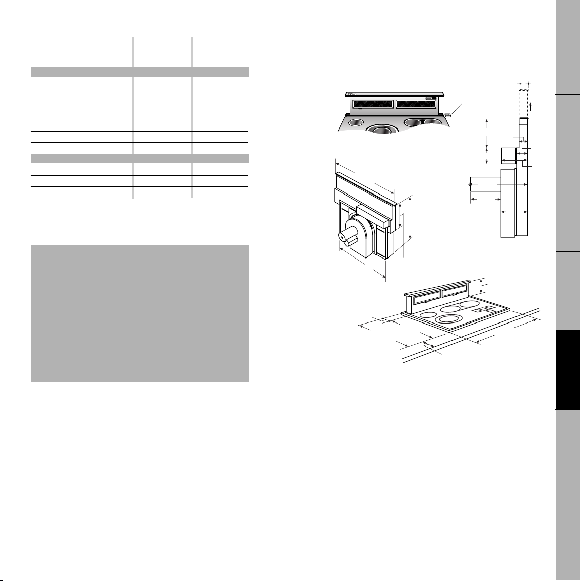
Downdraft Vent Features
ZVB36SBSS ZVB30SBSS
ZVB36WBWW ZVB30WBWW
ZVB36BBBB ZVB30BBBB
Features
Variable Speed Control ••
Downdraft Exhaust (CFM) 500 500
Removable Grease Filters ••
3-1/4" x 10" Rect. Duct ••
Separate Raise/Lower Switch ••
Indoor Remote Blower Kit JXRB57 JXRB57
Outdoor Remote Blower Kit JXBC57 JXBC57
General Features
Width (in inches) 36 30
KW Rating @ 120VAC 4.0 4.0
Amps @ 120V 5 5
Approx. Shipping Weight 62 lbs. 60 lbs.
Warranty Information
Full One Year Warranty
See written warranty for details.
Telescopic Downdraft Vent Systems
Product Dimensions
The vent raises 8-1/2" above the countertop surface when
in use. The vent can be retracted almost flush with the
countertop with a separate switch.
Diagram 28
36" or 30"
Width
27"
Separate
Raise/Lower
Switch
7-1/2"
3-1/4"
12-3/8"
5-3/8"
Diagram 30
2-1/4"
2"
8-1/2"
Lift
3-1/4"
6-3/8"
7"
Features
14-3/4"
• These downdraft vent systems are ideal for island and
peninsula cooking centers because they retract, nearly flush
with the cooktop.
Diagram 29
26"
8-1/2"
• All models have a separate raise/lower switch which must
be installed in a separate location from the vent.
• The Telescopic downdraft vents are available in white, black
and stainless steel to coordinate with Monogram gas and
electric cooktops.
• A slide knob controls the variable speed fan, with up to 500
CFM venting power.
Diagram 31
2-1/8"
Extra Deep
Flat Surface
Required
Cooktop
Depth
Clearance to
Front Edge
Cooktop
Width
• Two filters remove easily for cleaning.
Installation Requirements
Installation Flexibility
• To help align the vent discharge to house ductwork, the
entire blower mounting plate can be shifted, up to 3-1/2",
side to side.
• The entire blower can be rotated 30° to the left or right sides.
• The blower assembly is shipped to discharge straight down, it
may be removed and turned 90° to discharge left or right.
Accessories
• For quiet operation, the blower and motor assembly can be
installed on an outside wall with the JXBC57 outdoor cover
accessory.
• The blower and motor may also be installed below the
cabinet floor with the JXRB57 kit.
108 109
Consider the location of the separate raise/lower switch.
Countertop: The countertop must have a deep flat surface
to accommodate the cooktop and the vent. Countertops
with a rolled front edge and backsplash may not provide the
flat surface area required.
Base Cabinet: The base cabinet must be deep enough to
accommodate the min. clearance to the front edge of the
countertop, the cooktop burner box and the vent.
For accurate planning, installation combinations for the
vent and the specific Monogram cooktop are shown
together on the following pages.
Refer to Installation Instructions for details
Pub. No. 49-80126
Products
Refrigeration
Professional
Cooking Products
Warming Drawers
Ovens, Microwave
Cooking Surfaces
Venting Systems
Dishwashers, Chef’s
Washers, Compactors
Outdoor
Cooking Centers
Page 10
Telescopic Downdraft Vent Systems
Advance Planning
Before you begin you MUST:
1. Review countertop dimension shown on the following
pages to be sure you will have enough flat countertop
surface depth.
2. Check to be sure that the total flat countertop depth
required, plus the min. clearance from cutout to front
edge, allows enough space for a backsplash.
3. Review the cabinet illustrations. Check to be sure that
the interior cabinet depth will house the cooktop
burner box, the vent and the cutout clearance from the
front.
4. When countertop and cabinet depth present a problem,
review Creative Solutions.
5. Review the installation instructions carefully and
completely to accurately plan the location, clearances
and ductwork requirements.
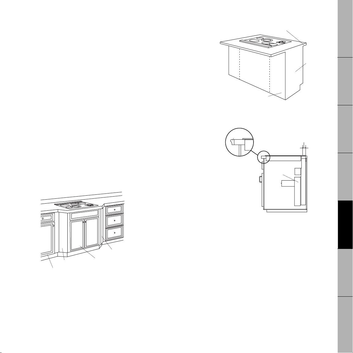
Creative Installation Solutions
When installation requires deeper countertops or cabinets,
adjustments can be made. Review the following installation
examples for solutions that can work in your kitchen design.
Maintain Cutout Clearances
to Front Edge as Specified
Creative Installation Solutions
Countertop Overhang per Cooktop
Clearances Must be Maintained
1-7/8"
End
Panel
B18
Base Sink
BS30 to BS42
Diagram 33
Cover Panel
B18
Island or peninsula, use an extra deep countertop. The
countertop overhang at the front can be adjusted to meet
setback to cutout requirements.
Trim
Add a Bullnose
Trim or Decorative
Molding to
Increase
Countertop
Depth and to
Maintain
Required
Clearance From
Front Edge
DOWNDRAFT
VENT
Products
Refrigeration
Professional
Cooking Products
Warming Drawers
Ovens, Microwave
Cooking Surfaces
Diagram 34
Decorative Trim
When the cutout to front edge requirement is more
than 2", add a bullnose trim to the front edge of the
countertop. The additional trim allows the cooktop to
be moved forward, providing additional countertop
depth and interior cabinet space.
Diagram 32
Filler Panel
Base Cabinet
Filler Panel
Base Sink
Against-the-wall installation, move the base cabinet
forward, 3" to 5". Filler panels or complimentar y
moldings can be added to the exposed cabinet sides.
110 111
Venting Systems
Dishwashers, Chef’s
Washers, Compactors
Outdoor
Cooking Centers
Page 11
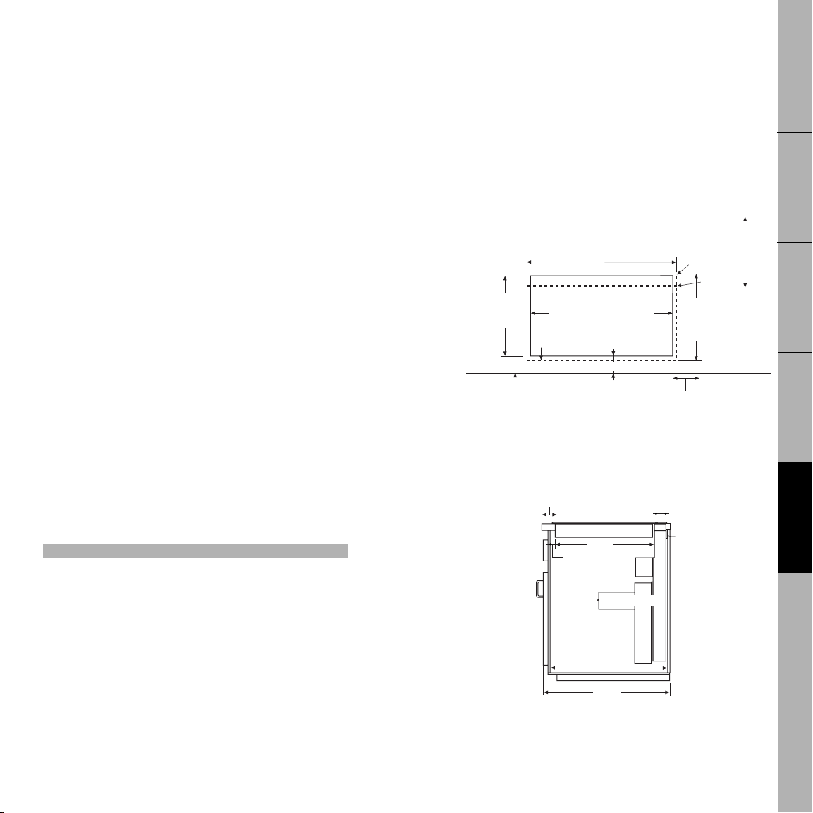
Clearances:
2-1/2" Min. Clearance to Cutout
34" Cooktop and Vent Cutout
5/8" Cooktop Overlap
21-3/4"
Cutout
Depth
1/4" Overlap
22-1/2"
Total Flat
Surface
Required
1/8" Gap
36"
Front Edge
of Countertop
1-3/4" Min. Cooktop Cutout to Rear
Vertical Combustible Surface
2" Min. Cutout
to Side Walls
• The downdraft system with blower, motor and ductwork will
occupy the cabinet below the countertop and cooktop.
• The blower/motor assembly can be located below the cabinet
floor. The assembly will fit between 16" floor joists. Order
JXRB57 for indoor remote locations. In this installation a
transition to 6" round is required.
• The blower motor assembly can also be installed outdoors.
Downdraft Vent and Cooktop
Combination Cutout and Clearances
Identify the cutout illustration for the cooktop model you
are installing.
Note: Standard countertops extend 25" from a wall.
Standard 24" deep cabinets are 22-3/4" from the inside
front to the back wall. When present, a 3/4" thick support
rail at the top rear shortens the inside depth to 22".
Order JXBC57 for remote blower installations outdoors. In
this installation one or two 3-1/4 x 10" to 6" round transitions
may be required.
36" Vent with Electric Cooktops, ZEU769
Installation Requirements
Ductwork:
Plan the ductwork to vent to the outdoors.
• Use the shortest and straightest duct run possible. The
maximum permissible equivalent length for duct run is
150 feet. Refer to “Duct Fittings” chart in the installation
instructions to calculate equivalent length.
• The downdraft blower system is designed to use 3-1/4" x 10"
ductwork. It can be transitioned to 6" round.
Electrical and Gas Locations:
• Gas or electrical outlets cannot be placed on the back wall of
the cabinet because it may interfere with the downdraft
plenum.
• The vent and a Monogram gas cooktop combination may
operate from the same 120V standard duplex outlet. Electric
cooktops must operate from a separate 240V junction box.
Diagram 35
Countertop
Requires 22-1/2" flat countertop surface and 24-3/8" total countertop depth.
Monogram Downdraft Vent And
Cooktop Installation Combinations
Install Downdraft vents with any Monogram Cooktop.
(except professional cooktops)
Vent Cooktop Model
ZVB30 ZEU30RSFSS, ZEU30RWFWW, ZEU30RBFBB
ZVB36 ZEU36RSFSS, ZEU36RWFWW, ZEU36RBFBB
112 113
ZEU769SCSS, ZEU769TCWW, ZEU769BCBB
ZGU375NSDSS, ZGU375LSDSS,
ZGU36GGSDSS, ZGU36GGTDWW, ZGU36GGBDBB
Diagram 36
Cabinet
Requires 22-1/2" inside cabinet depth.
– Remove rear support rail.
2-1/2" to
Cutout
3/4"
22-3/4" to Back Wall
22" to Support Rail
ZEU769 Cooktop
19-7/8"
DOWNDRAFT VENT
24-3/4"
1-7/8"
3/4"
Thick
Support
Rail
Products
Refrigeration
Professional
Cooking Products
Warming Drawers
Ovens, Microwave
Cooking Surfaces
Venting Systems
Dishwashers, Chef’s
Washers, Compactors
Outdoor
Cooking Centers
Page 12
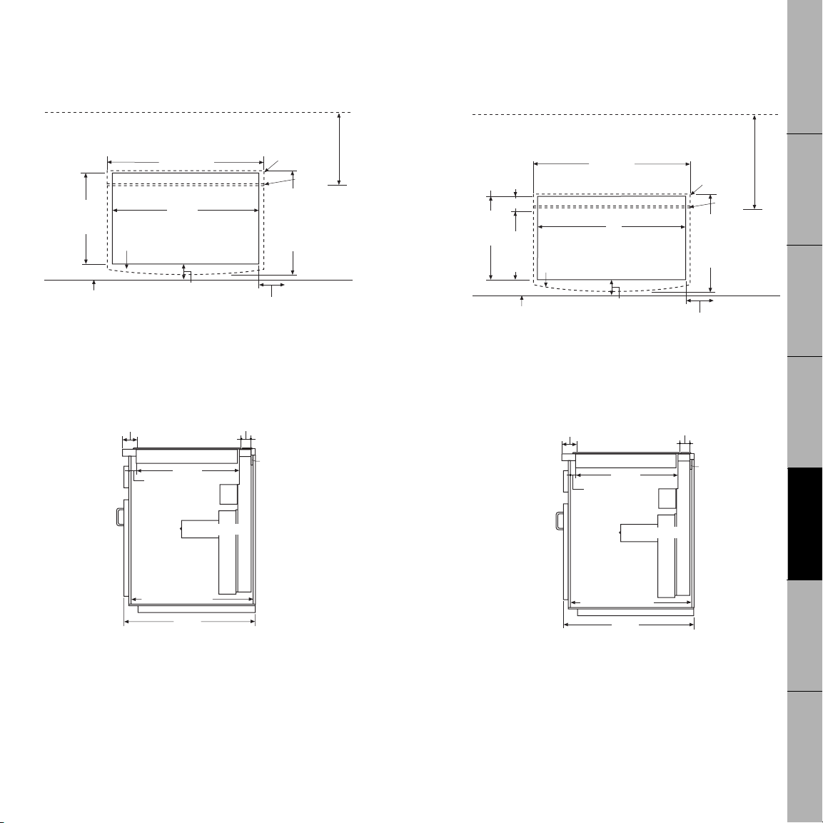
30" Vent with Digital Cooktops, ZEU30R
34"
Cooktop and Vent Cutout
5/8" Cooktop Overlap
(1-1/8" at Center)
21-3/4"
Cutout
Depth
19-1/8"
Cooktop
Cutout
Depth
2-3/4"
1/4" Overlap
23" (SS)
22-7/8" (B,W)
Total Flat
Surface
Required
1/8" Gap
36-1/8" (SS)
36" (B,W)
2-1/2" Min.
Clearance to Cutout
Front Edge
of Countertop
1-3/4" Min. Cooktop Cutout to Rear
Vertical Combustible Surface
2" Min. Cutout
to Side Walls
Installation Requirements
Downdraft Vent and Cooktop
Combination Cutout and Clearances
1-3/4" Min. Cooktop Cutout to Rear
Vertical Combustible Surface
22-1/4"
Cutout
Depth
29-7/8" (SS)
29-3/4" (B,W)
28-1/2"
Cooktop Area Cutout
5/8" Cooktop Overlap
(1-1/8" at Center)
1/4" Overlap
1/8" Gap
23-1/2" (SS)
23-3/8" (B,W)
Total Flat
Surface
Required
at Center
36" Vent with Digital Cooktops, ZEU36R
Installation Requirements
Downdraft Vent and Cooktop
Combination Cutout and Clearances
Products
Refrigeration
Professional
Cooking Products
Front Edge
of Countertop
Diagram 37
Countertop
Requires 23-3/8" (B,W) 23-1/2" (SS) flat countertop surface. Requires 24-3/4"
(B,W) and 24-7/8" (SS) total countertop depth.
2-1/2" to
Cutout
Diagram 38
Cabinet
Requires 23" inside cabinet depth.
– See Creative Solutions, install in an island or move cabinet base forward.
114 115
2-1/2" Min.
Clearance to Cutout
ZEU30 Cooktop
20-3/8"
3/4"
DOWNDRAFT VENT
22-3/4" to Back Wall
22" to Support Rail
24-3/4"
2" Min. Cutout
to Side Walls
1-7/8"
3/4"
Thick
Support
Rail
Diagram 39
Countertop
Requires 22-7/8" (B,W) 23" (SS) flat countertop surface. Requires 24-1/4"
(B, W) and 24-3/8" (SS) total countertop depth.
Diagram 40
2-1/2" to
Cutout
3/4"
22-3/4" to Back Wall
22" to Support Rail
ZEU36 Cooktop
19-7/8"
DOWNDRAFT VENT
24-3/4"
1-7/8"
Cabinet
Requires 22-1/2" inside cabinet depth.
– Remove rear support rail.
3/4"
Thick
Support
Rail
Warming Drawers
Ovens, Microwave
Cooking Surfaces
Venting Systems
Dishwashers, Chef’s
Washers, Compactors
Outdoor
Cooking Centers
Page 13
36" Vent with Gas Cooktops, ZGU375
Installation Requirements
Downdraft Vent and Cooktop
Combination Cutout and Clearances
3-3/8" Min. Cooktop Cutout to Rear
Vertical Combustible Surface
9/16"
36-1/2"
34" Vent Cutout
2-9/16"
21-7/16"
Cutout
Depth
Diagram 41
18-7/8"
Cooktop
Cutout
Front Edge
of Countertop
35-5/16"Cooktop
Area Cutout
7/16" Cooktop Overlap
(1-1/4" At Center)
2-3/4" Min.
Clearance to Cutout
Countertop
Requires 22-3/4" flat countertop surface and 24-1/4" total countertop depth.
2-3/4" to
Cutout
9/16"
1/4" Overlap
22-3/4"
Total Flat
Surface
Required
11-9/16" Min. Cutout
to Side Walls
1-7/8"
1/8" Gap
36" Vent with Gas Cooktops, ZGU36GG
Installation Requirements
Downdraft Vent and Cooktop
Combination Cutout and Clearances
2-1/4" Min. Cooktop Cutout to Rear
Vertical Combustible Surface
36"
21-3/4"
Diagram 43
Cutout
Depth
Front Edge
of Countertop
34" Cooktop and Vent Cutout
13/16" Cooktop Overlap
(1-1/2" at Center)
2-1/2" Min.
Clearance to Cutout
Countertop
Requires 23-3/8" (B,W), 23-1/2" (SS) flat countertop surface. Requires 24-3/8"
(B, W) and 24-1/2" (SS) total countertop depth.
2-1/2" to
Cutout
23-1/2" (SS)
23-3/8" (B,W)
6" Min. Cutout
to Side Walls
1-7/8"
1/4" Overlap
1/8" Gap
Total Flat
Surface
Required
at Center
Products
Refrigeration
Professional
Cooking Products
Warming Drawers
Ovens, Microwave
ZGU375 Cooktop
19-7/16"
1"
DOWNDRAFT VENT
22-3/4" to Back Wall
22" to Support Rail
Diagram 42
24-3/4"
Cabinet
Requires 22-5/16" inside cabinet depth.
– Remove rear support rail.
3/4"
Thick
Support
Rail
Diagram 44
Cabinet
Requires 22-11/16" inside cabinet depth.
– Remove rear support rail.
ZGU36 Cooktop
20-1/16"
3/4"
DOWNDRAFT VENT
22-3/4" to Back Wall
22" to Support Rail
24-3/4"
3/4"
Thick
Support
Rail
116 117
Cooking Surfaces
Venting Systems
Dishwashers, Chef’s
Washers, Compactors
Outdoor
Cooking Centers
 Loading...