

GE Over the Range Microwave Oven Installation Instructions

Installation Over the Range
Instructions Microwave Oven
BEFORE YOU BEGIN
Read these instructions completely and carefully.
•
IMPORTANT – Save these
instructions for local inspector’s use.
•
IMPORTANT – Observe all
governing codes and ordinances.
• Note to Installer – Be sure to leave these
instructions with the Consumer.
• Note to Consumer – Keep these
instructions for future reference.
• Skill level – Installation of this appliance requires
basic mechanical and electrical skills.
• Proper installation is the responsibility of the installer.
• Product failure due to improper installation is not
covered under the Warranty.
English/Spanish
READ CAREFULLY.
KEEP THESE INSTRUCTIONS
31-7000092 Rev. 1 03-20 GEA
.

Installation Instructions
DANGER
This is the safety alert symbol. This symbol alerts you to potential hazards that can kill or hurt you and others.
All safety messages will follow the safety alert symbol and the word “DANGER”, “WARNING”, or “CAUTION”. These
words are defined as:
Indicates a hazardous situation which, if not avoided, will result in death or serious injury.
WARNING
CAUTION
Indicates a hazardous situation which, if not avoided, could result in death or serious injury.
Indicates a hazardous situation which, if not avoided, could result in minor or moderate injury.
IMPORTANT SAFETY INSTRUCTIONS
A qualified electrician must perform a ground
continuity check on the wall receptacle before
beginning the installation to ensure that the
outlet box is properly grounded. If not properly
grounded, or if the wall receptacle does not meet
electrical requirements noted (under ELECTRICAL
REQUIREMENTS), a qualified electrician should be
employed to correct any deficiencies.
WARNING
Risk of Electric Shock.
Can cause injury or
death: Remove house
fuse or
open circuit breaker
before beginning
installation to avoid
severe or fatal shock
injury.
WARNING
RISK OF ELECTRIC SHOCK
WARNING
cut, deform or remove any of the prongs from the
power cord. Do not use with an extension cord.
Failure to comply may cause fire.
Can cause injury or death: DO
NOT, under any circumstances,
ELECTRICAL REQUIREMENTS
Product rating is 120 volts AC, 60 Hertz, 14.5 amps
and 1.7 kilowatts. This product must be connected to
a supply circuit of the proper voltage and frequency.
Wire size must conform to the requirements of
the National Electrical Code or the prevailing local
code for this kilowatt rating. The power supply cord
and plug should be brought to a separate 15- to
20-ampere branch circuit single grounded outlet. The
outlet box should be located in the cabinet above
the microwave oven. The outlet box and supply
circuit should be installed by a qualified electrician
and conform to the National Electrical Code or the
prevailing local code.
Risk of Electric
Shock. Can cause
Ensure
proper
ground
exists before
use
The power cord of this appliance is equipped
with a three-prong (grounding) plug which mates
with a standard three-prong (grounding) wall
receptacle to minimize the possibility of electric
shock hazard from this appliance.
Where a standard two-prong wall receptacle is
encountered, it must be replaced with a properly
grounded three-prong wall receptacle, installed
by a qualified electrician.
injury or death: THIS
APPLIANCE MUST
BE PROPERLY
GROUNDED to avoid
severe or fatal shock.
FOR YOUR SAFETY:
CAUTION
capable of supporting the cabinet load, in addition to
the added weight of this 63–85 pound product, plus
additional oven loads of up to 50 pounds or a total
weight of 113–135 pounds.
CAUTION
arrangements such as an island or a peninsula. It must
be mounted to BOTH a top cabinet AND a wall.
CAUTION
due to excessive weight of the microwave oven) or
property damage, you will need two people to install
this microwave oven.
For personal safety,
the mounting surface must be
For personal safety, this product
cannot be installed in cabinet
To avoid the risk of personal
injury (back injury or other injuries
2 31-7000092 Rev. 1
Installation Instructions
HOOD EXHAUST
NOTE: Read these next two pages only if you plan to vent your exhaust to the outside. If you plan to recirculate the air back
into the room, proceed to page 11.
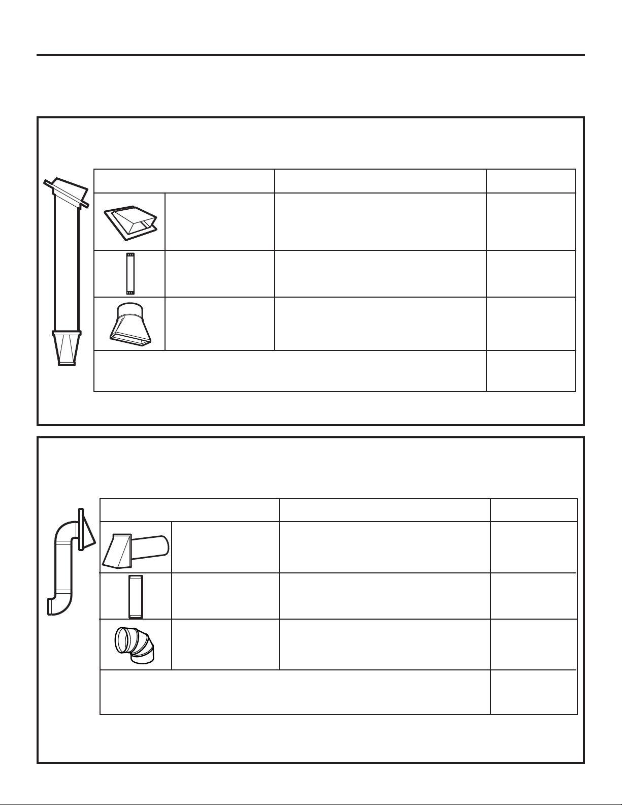
OUTSIDE TOP EXHAUST (EXAMPLE ONLY)
The following chart describes an example of one possible
ductwork installation.
EQUIVALENT NUMBER
DUCT PIECES
Roof Cap 24 Ft. x (1) = 24 Ft.
12 Ft. Straight Duct 12 Ft. x (1) = 12 Ft.
(6″Round)
Rectangular-to-Round 5 Ft. x (1) = 5 Ft.
Transition Adaptor*
LENGTH x USED = LENGTH
Equivalent lengths of duct pieces are based on actual tests and
reflect requirements for good venting performance with any vent hood.
Total Length = 41 Ft.
* IMPORTANT: If a rectangular-to-round transition adaptor is used, the bottom corners of the damper
will have to be cut to fit, using the tin snips, in order to allow free movement of the damper.
OUTSIDE BACK EXHAUST (EXAMPLE ONLY)
The following chart describes an example of one possible
ductwork installation.
EQUIVALENT NUMBER
DUCT PIECES LENGTH* x USED = LENGTH
Wall Cap 40 Ft. x (1) = 40 Ft.
3 Ft. Straight Duct 3 Ft. x (1) = 3 Ft.
(31⁄4″x10″Rectangular)
90° Elbow 10 Ft. x (2) = 20 Ft.
Equivalent lengths of duct pieces are based on actual tests and
reflect requirements for good venting performance with any vent hood.
Total Length = 63 Ft.
NOTE: For back exhaust, care should be taken to align exhaust with space between studs, or wall
should be prepared at the time it is constructed by leaving enough space between the wall studs to
accommodate exhaust.
31-7000092 Rev. 1 3
Installation Instructions
NOTE: If you need to install ducts, note that the total
duct length of 31⁄4″x10″rectangularor6″diameterround
duct should not exceed 140 equivalent feet.
Outside ventilation requires a HOOD EXHAUST DUCT.
Read the following carefully.
NOTE: It is important that venting be installed using
the most direct route and with as few elbows as possible.
This ensures clear venting of exhaust and helps prevent
blockages. Also, make sure dampers swing freely and
nothing is blocking the ducts.
Exhaust connection:
The hood exhaust has been designed to mate with
a standard 31⁄4″x10″rectangularduct.
If a round duct is required, a rectangular-to-round
transition adaptor must be used. Do not use less than
a 6″ diameter duct.
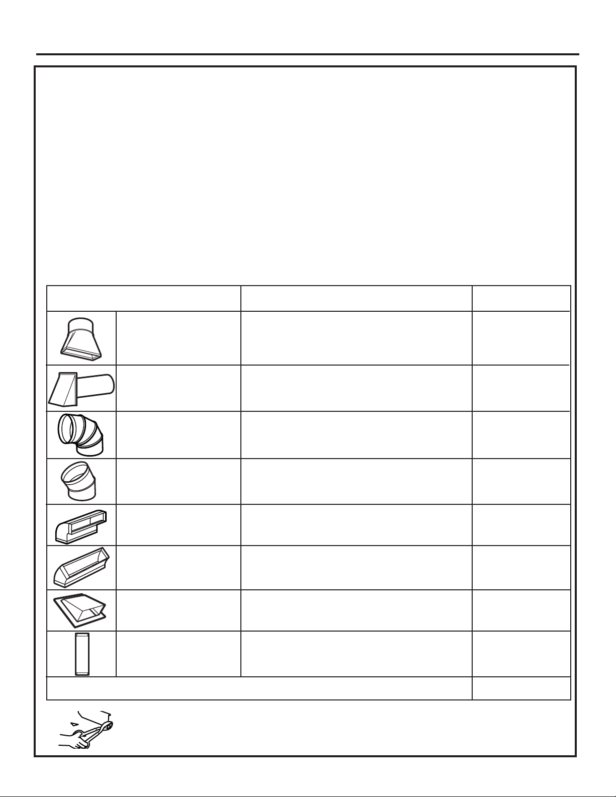
DUCT PIECES
Rectangular-to-Round 5 Ft. x ( ) = Ft.
Transition Adaptor*
LENGTH x USED = LENGTH
EQUIVALENT NUMBER
Maximum duct length:
For satisfactory air movement, the total duct length of
31⁄4″x10″rectangularor6″diameterroundductshould
not exceed 140 equivalent feet.
Elbows, transitions, wall and roof caps,
etc., present additional resistance to airflow and are
equivalent to a section of straight duct which is longer
than their actual physical size. When calculating the total
duct length, add the equivalent lengths of all transitions
and adaptors plus the length of all straight duct sections.
The chart below shows you how to calculate total
equivalent ductwork length using the approximate feet of
equivalent length of some typical ducts.
Wall Cap 40 Ft. x ( ) = Ft.
90° Elbow 10 Ft. x ( ) = Ft.
45° Elbow 5 Ft. x ( ) = Ft.
90° Elbow 25 Ft. x ( ) = Ft.
45° Elbow 5 Ft. x ( ) = Ft.
Roof Cap 24 Ft. x ( ) = Ft.
StraightDuct6″Roundor 1Ft. x () = Ft.
31⁄4″x10″Rectangular
Total Ductwork = Ft.
* IMPORTANT: If a rectangular-to-round transition
adaptor is used, the bottom corners of the
damper will have to be cut to fit, using the tin
snips, in order to allow free movement of the
damper
.
Equivalent lengths of duct pieces are based on actual tests
and reflect requirements for good venting performance with
any vent hood.
4 31-7000092 Rev. 1

Installation Instructions
DAMAGE – SHIPMENT INSTALLATION
• If the unit is damaged in shipment, return the
unit to the store in which it was bought for repair or
replacement.
• If the unit is damaged by the customer, repair or
replacement is the responsibility of the customer.
• If the unit is damaged by the installer (if other
than the customer), repair or replacement must
be made by arrangement between customer and
installer.
PARTS INCLUDED
HARDWARE PACKET
Part Quantity
Wood screws (1/4” x 2”) 2
Toggle bolts (and wind
nuts) (3/16” x 3”)
2
ADDITIONAL PARTS
Part Quantity
Top Cabinet
Template
Rear Wall
Template
Installation
Instructions
Separately
Packed Grease
Filter
Cover plate (for
Room Venting
installation)
1
1
1
2
1
Self-aligning machine
screws (1/4” - 28 x 3
1/4”)
Nylon Grommet (for
metal cabinets)
Tapping screws (for
attaching the damper
duct connector)
One power cord clamp
and One dark-colored
mounting screw (to hold
the power cord)
You will find the installation hardware contained
in a packet with the unit. Check to make sure you
have all these parts.
NOTE: Some extra parts are included.
2
1
3
1
31-7000092 Rev. 1 5
Installation Instructions
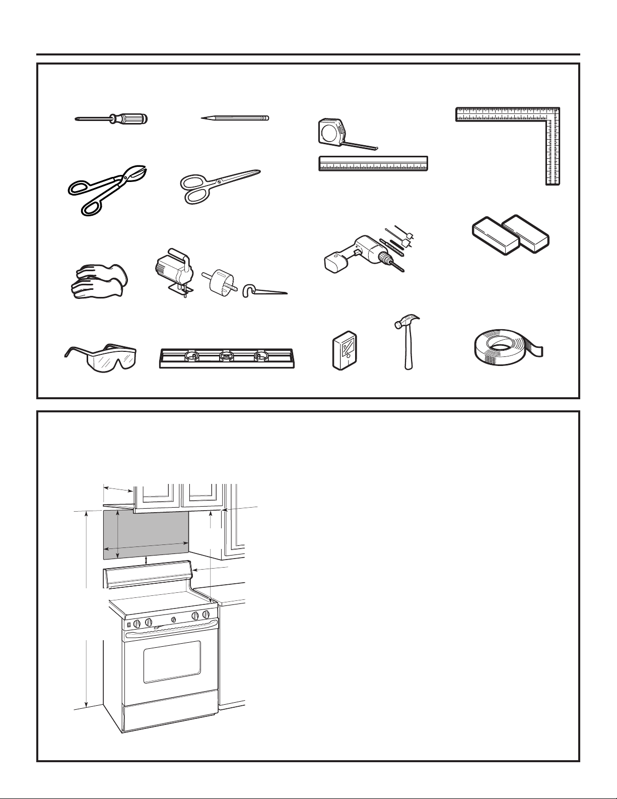
TOOLS YOU WILL NEED
#1 and #2
Phillips
screwdriver
Tin snips (for cutting
damper, if required)
Gloves
Safety goggles
Pencil
Scissors (to cut
template, if necessary)
Saw (saber, hole or keyhole)
Level
Ruler or tape measure and
straight edge
3
Electric drill with
1
⁄2″and5⁄8″drillbits
Stud
finder
⁄16″,7⁄16″,
Hammer (optional)
Carpenter square
(optional)
Filler blocks or scrap
wood pieces, if needed
for top cabinet spacing
(used on recessed
bottom cabinet
installations only)
Duct and masking
tape
MOUNTING SPACE
*13″max.
1
16-
⁄2″
30″
2″
66″ormore
from the floor
to the top of
the oven
30″
min.
Bottom edge of
cabinet needs
tobe30″or
more from the
cooking surface
Backsplash
NOTES:
•Thespacebetweenthecabinetsmustbe30″wide
and free of obstructions.
• This oven is for installation over ranges up to
36″wide.
• If the space between the cabinets is greater than
30”, a Filler Panel Kit may be used to fill in the gap
between the microwave oven and the cabinets. Your
Owner’s Manual contains the kit number for your
model.
• If you are going to vent your oven to the outside, see
Hood Exhaust Section for exhaust duct preparation.
• When installing the oven beneath smooth, flat
cabinets, be careful to follow the instructions on the
top cabinet template for power cord clearance.
• * 13” max: for standard installation, 15” cabinet
depth requires additional steps using an additional
installation kit JX15BUMPWW/BB.
• For models with top venting holes: Do not allow
cabinetry or other objects to block the airflow of the vent.
• Café branded over-the-range microwaves should only
be installed over Café branded ranges. Installation over
any other range may result in surface temperatures that
can cause burns.
• All other over-the-range microwaves should not be
installed over any cooktop or range with a combined
BTU greater than 60,000 BTU.
6 31-7000092 Rev. 1
Installation Instructions
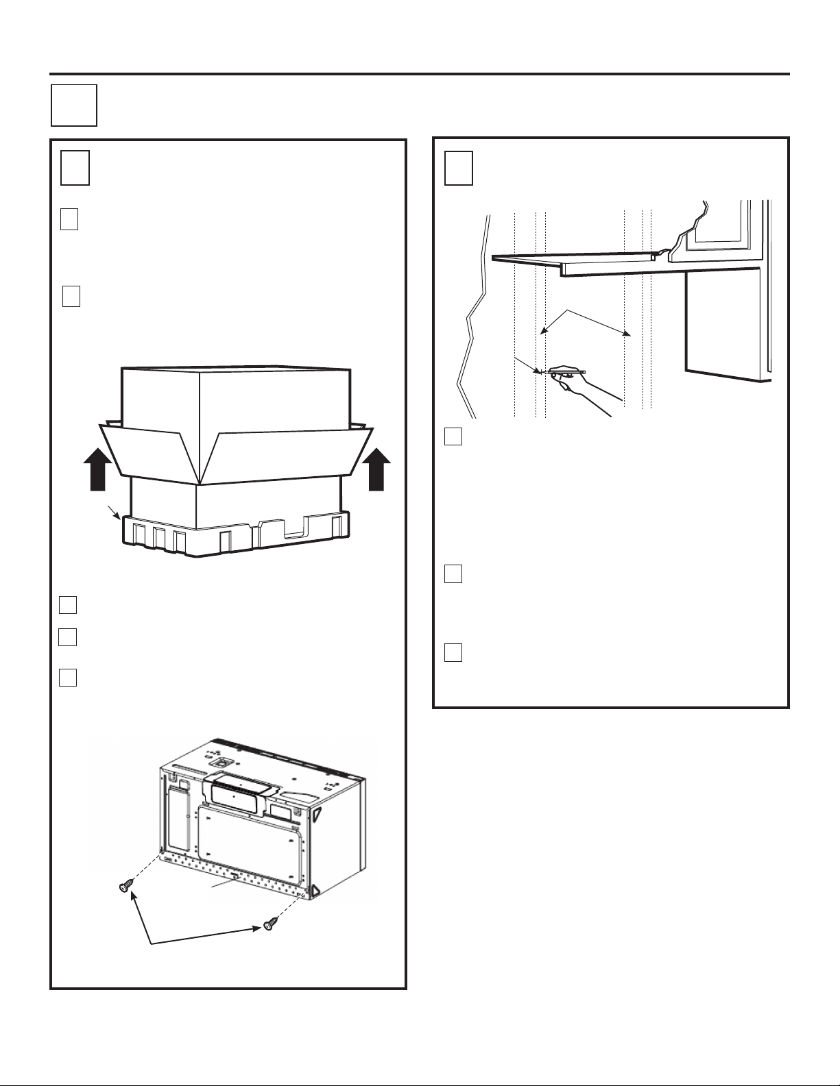
PLACEMENT OF THE MOUNTING PLATE
1
REMOVING THE MICROWAVE
A
.
OVEN FROM THE CARTON
Remove the installation instructions, filters, glass
1
tray, mounting plate, and the small hardware bag.
Do not remove the foam protecting the front of the
oven.
Fold back all 4 carton flaps fully against carton
2
sides. Then carefully roll the oven and carton over
onto the top side. The oven should be resting in
the foam.
Carton
foam
3
Pull the carton up and off the oven.
4
Set the oven upright. Remove and properly discard
plastic bags and foam packing.
Remove the 2 screws from the mounting plate.
5
This plate can be used as the rear wall template
and will be used for mounting. You may discard
these screws.
B
.
FINDING THE WALL STUDS
Wall
Studs
Center
1
Find the studs, using one of the following
methods:
A. Stud finder – a magnetic device which
locates nails.
OR
B. Use a hammer to tap lightly across the
mounting surface to find a solid sound.
This will indicate a stud location.
After locating the stud(s), find the center by
2
probing the wall with a small nail to find the edges
of the stud. Then place a mark halfway between
the edges. The center of any adjacent studs
shouldbe16″or24″fromthismark.
3
Draw a line down the center of the studs.
THE MICROWAVE MUST BE CONNECTED TO
AT LEAST ONE WALL STUD.
Mounting
Plate
Screws
31-7000092 Rev. 1 7

Installation Instructions
DETERMINING MOUNTING PLATE LOCATION UNDER YOUR CABINET
C
Plate Position – beneath flat bottom
cabinet
Draw a vertical line on the wall at the center of the
30” wide space. Tape the Rear Wall Template onto
the wall matching the centerline and touching the
bottom of the cabinet
Plate Position – beneath recessed
bottom cabinet with front overhang.
Draw a line on the
back wall equal to
the depth of the front
overhang
30” to Cooktop
Plate Position – beneath framed
recessed cabinet bottom
30” to Cooktop
Draw a vertical line on the wall at the center of the
30” space.
Tape the Rear Wall Template onto the wall
matching the centerline and touching the bottom
cabinet frame.
Your cabinets may have decorative trim that interferes
with the microwave installation. Remove the decorative
trim to install the microwave properly and to make it
level.
THE MICROWAVE MUST BE LEVEL
Use a level to make sure the cabinet bottom is level.
If the cabinets have a front overhang only, with no
back or side frame, install the mounting plate down the
same distance as the front overhang depth. This will
keep the microwave level.
1
Measure the inside depth of the front overhang.
Draw a horizontal line on the back wall an equal
2
distance below the cabinet bottom as the inside
depth of the front overhang.
For this type of installation with front overhang only,
3
align the Rearwall Template with this horizontal
line, not touching the cabinet bottom as described
in Step D.
8 31-7000092 Rev. 1
 Loading...