

Page 1

Optima XR640
Optima* XR646
Digital Radiographic System
Operator Manual
5495975-1EN
Rev. 9
© 2013-2017 General Electric Company. All rights reserved.
5495975-1EN Rev.9
© 2013-2017 General Electric Company. All rights reserved.
Page 2

5495975-1EN Rev.9
© 2013-2017 General Electric Company. All rights reserved.
Page 3

X-RAY Caution
X-RAY Caution
Though this equipment is built to the highest standards of electrical and mechanical safety, the useful xRay beam becomes a source of danger in the hands of the unauthorized or unqualified operator. Excessive exposure to x-radiation causes damage to human tissue.
Therefore, adequate precautions must be taken to prevent unauthorized or unqualified persons from
operating this equipment or exposing themselves or others to its radiation.
Before operation, persons qualified and authorized to operate this equipment should be familiar with the
recommendation of the International Commission on Radiological Protection, contained in the latest
Annals of the ICRP, and with applicable national standards and should have been trained in use of the
equipment.
5495975-1EN Rev.9 i-i
© 2013-2017 General Electric Company. All rights reserved.
Page 4

Medical Device Directive
Medical Device Directive
This product complies with the following requirements:
Council Directive 93/42/EEC concerning medical devices when it bears the following CE marking of conformity:
The location of the CE mark label on the equipment is in the service system manual.
EU Authorized Representative:
GE Medical Systems SCS
283 rue de la Minière
78530 BUC, FRANCE
Green QSD 1990 Standard issued by MDD (Medical Devices Directorate, Department of Health, UK).
Medical Device Good Manufacturing Practice Manual issued by the FDA (Food and Drug Administration,
Department of Health, USA).
Underwriters' Laboratories, Inc. (UL), an independent testing laboratory.
Canadian Standards Association (CSA).
International Electrotechnical Commission (IEC), international standards organization, when applicable.
GE Healthcare reserves the right to make changes in specifications and features shown herein, or discontinue the product described at any time without notice or obligation.
The original language of this manual is English.
5495975-1EN Rev.9 i-ii
© 2013-2017 General Electric Company. All rights reserved.
Page 5
Contact Information
Contact Information
Optima XR646
Optima XR646 Systems can be sold by the below names and be manufactured by the below manufacturers.
Model Name Manufacturer (*)
Manufacturing Site
Optima XR646 GE HUALUN
MEDICAL SYSTEMS
CO. Ltd
GE MEDICAL
SYSTEMS, LLC
Manufacturer address
No.1 Yong Chang North Road Beijing Economic
Technological Development Zone
BEIJING 100176 CHINA
3000 North Grandview Blvd
WAUKESHA, WI 53188 UNITED STATES
5495975-1EN Rev.9 i-iii
© 2013-2017 General Electric Company. All rights reserved.
Page 6
Revision History
Revision History
Revision Date Description of Change
1 19th Dec 2013 Initial release.
2 28 Nov 2014 New Design Change:
Update Table Warning Labels and picture of lock
Add a new section of “Digital Cassette Imaging in Extended Table Detector Tray” in
Chapter 8.
Update wallstand light ring in Chapter 8.
Add 120cm wallstand grid and 120cm table grid in Chapter 8.
Add image recovery in Chapter 10.
Add field size of Collimator in Chapter Appendix B.
Update some screenshots.
3 24 Mar 2015 Add Brazil UWB Certification Information in Chapter 2
Update Identification Plate No. of Workstation PC (Z420) into 5840000-3 in Chapter
2
Update digital detector specifications in Chapter 7
Modify Image pasting drawing of illustration of acquisition in Chapter 13
Update Power Supply Conditions in Appendix B: Specifications
4 21 July 2015 Add a warning explanation to patient load label in Chapter 2
Delete “United states” from “United states Federal law restricts this device to sale by
or on the order of a physician” in Chapter 1 and Chapter 2
Flash Pad Detector (URP) part No. 5340000-3 be updated into 5340000-7 in Chapter
2
Workstation PC (Z420) part No. 5840000-3 be updated into 5843000-3 in Chapter
2
Add a sentence of “Please wait at least 60 seconds
Perform QAP section of Chapter 14
5 06 Nov 2015 Update patient load label and its instruction in Chapter 2
6 18 Feb 2016 Added 2nd Manufacturer in Contact Information.
added 5843001-3 into Identification and Compliance Plates in Chapter 2.
7 01 Apr 2016 Update Contact Information
Add UDI Label into Identification and Compliance Plates in Chapter 2
in Chapter 2.
......” to solve RCN test fail issue in
Revision History
5495975-1EN Rev.9 i-iv
© 2013-2017 General Electric Company. All rights reserved.
Page 7

Revision History
Revision History
Revision Date Description of Change
8 23 Jan 2017 To add Standard Table & Manual Wallstand and upgraded Collimator, detailed
revise happened together with having corrected legend errors as below.
1. In chapter 2: Revised Table 2-5 Maximum Attenuation Equivalent mm AL with
adding new items and correcting legend errors under section General Use Warnings; Revised Table 2-14 Identification Plate with adding new items and correcting
legend errors under section Identification Plate and Compliance Plates Location;
Added
a new section Standard Table Warning Labels under section NRTL Listed
Label; Added a warning for standard table load capability under section Patient
Positioning Warnings;
2. In chapter 4: Revised Figure 4-8 Emergency Stop buttons and corrected a Caution under section Emergency Stop.
3. In chapter 5: Corrected a Caution under section Emergency Stop button.
4. In chapter 7: Added “Do not stand on the grid” under section Grid Handling.
5. In chapter 8: Revised the configurations and the note in section Configurations;
Revised Table 8-1 Major system components with adding new components under
section Component Identification; Revised Table 8-2 Available Options with adding
new options under section Available Accessories; Revised multi-leaf collimator
description and Figure 8-13 Collimator controls under section Multi-Leaf Collimator;
Revised Figure 8-14 Multi-leaf collimator display under section Collimator Display; In
section Digital Wallstand, added word “digital” in several places in order to differentiate Digital Wallstand with new Manual Wallstand; added Wallstand chin rest as
applied part. Added a new section Manual Wallstand after section Digital Wallstand; In section Digital Table, added word “digital” in several places in order to differentiate Digital Table with new Standard Table; revised a Caution of item 7 in table
8-13, too. Added a new section Standard Table after Digital Table section; Revised
section Digital Cassette Imaging in Extended Table Detector Tray with clinical input;
Added a new section Standard Table Hand Grips and Compression Band after section Digital Table Hand Grips and Compression Band; Corrected an error on Lateral
Bridge Lengths by deleting 4.5 meter bridge (option).
6. In chapter 10: Added a Caution for labeling mitigation following up; Added a note
in section Conduct a Wallstand Exam. Added a note in section Conduct a Table Top
Exam and section Conduct a Cassette Exam.
7. In chapter 13: deleted “(not available in USA)” at the title “Dual Energy”.
8. In chapter 14: corrected the wrong service documentation part numbers under
section General and Periodic Maintenance Schedule.
9. In chapter 15: corrected an error in the first paragraph under section Add or Edit
DICOM Printers; Added a caution into section Retrieve Protocol Database from CD or
DVD.
10. In Appendix B: added specifications for new Standard Table and Manual Wallstand. Meanwhile corrected some legend errors on OTS, tables, Wallstand and storage conditions.
What is more, Labeling category was cleaned up throughout this manual. Copyright
time was revised through this manual, too.
5495975-1EN Rev.9 i-v
© 2013-2017 General Electric Company. All rights reserved.
Page 8

Revision History
Revision History
Revision Date Description of Change
9 18 May 2017 This revise is revised for Wireless Regulatory Information and manual wallstand fol-
low up action in operator manual. Detailed as below.
1. In Medical Device Directive: Deleted original wireless Regulatory statement under
Medical Device Directive.
2. In chapter 2: Added a new sub_section Wireless Regulatory Information under
section UWB Compliance Statement; Added a Caution under section General Use
Warnings; Added a symbol under section Special Notices; Added a Caution under
section Patient Positioning Warnings.
3. In chapter 5: Added a Caution under section General Acquisition.
4. In chapter 8: Revised Figure 8-36 and added a warning under section Remove or
Attach the Lateral Positioning Bar.
5. In chapter 14: Added some information on an expected service life of 10 years
under section Qualified Service section.
5495975-1EN Rev.9 i-vi
© 2013-2017 General Electric Company. All rights reserved.
Page 9

Table of Contents
Table of Contents
Chapter 1: Introduction
How to access the electronic version of a manual on a website. . . . . . . . . . . . . . . . . . . . . . . . . . . . . . . . . .1-1
Technical Manual Updates . . . . . . . . . . . . . . . . . . . . . . . . . . . . . . . . . . . . . . . . . . . . . . . . . . . . . . . . . . . . . . . . . . . . .1-2
Scope Of This Manual . . . . . . . . . . . . . . . . . . . . . . . . . . . . . . . . . . . . . . . . . . . . . . . . . . . . . . . . . . . . . . . . . . . . . . . . . .1-2
Prerequisite Skills . . . . . . . . . . . . . . . . . . . . . . . . . . . . . . . . . . . . . . . . . . . . . . . . . . . . . . . . . . . . . . . . . . . . . . . . . . . . . .1-2
Safety Information. . . . . . . . . . . . . . . . . . . . . . . . . . . . . . . . . . . . . . . . . . . . . . . . . . . . . . . . . . . . . . . . . . . . . . . . . . . . .1-3
Safety Notices . . . . . . . . . . . . . . . . . . . . . . . . . . . . . . . . . . . . . . . . . . . . . . . . . . . . . . . . . . . . . . . . . . . . . . . . . . . . . . . . .1-3
Graphic Conventions and Legends . . . . . . . . . . . . . . . . . . . . . . . . . . . . . . . . . . . . . . . . . . . . . . . . . . . . . . . . . . . . .1-4
Software User Interface Controls . . . . . . . . . . . . . . . . . . . . . . . . . . . . . . . . . . . . . . . . . . . . . . . . . . . . . . . . . . . . . . .1-5
Chapter 2: Safety and Regulatory
X-Ray Protection. . . . . . . . . . . . . . . . . . . . . . . . . . . . . . . . . . . . . . . . . . . . . . . . . . . . . . . . . . . . . . . . . . . . . . . . . . . . . . .2-1
Indications for Use. . . . . . . . . . . . . . . . . . . . . . . . . . . . . . . . . . . . . . . . . . . . . . . . . . . . . . . . . . . . . . . . . . . . . . . . . . . . . 2-1
Contraindication. . . . . . . . . . . . . . . . . . . . . . . . . . . . . . . . . . . . . . . . . . . . . . . . . . . . . . . . . . . . . . . . . . . . . . . . . . . . . . .2-2
Users . . . . . . . . . . . . . . . . . . . . . . . . . . . . . . . . . . . . . . . . . . . . . . . . . . . . . . . . . . . . . . . . . . . . . . . . . . . . . . . . . . . . . . . . . 2-2
Safety. . . . . . . . . . . . . . . . . . . . . . . . . . . . . . . . . . . . . . . . . . . . . . . . . . . . . . . . . . . . . . . . . . . . . . . . . . . . . . . . . . . . . . . . .2-2
Know the Equipment. . . . . . . . . . . . . . . . . . . . . . . . . . . . . . . . . . . . . . . . . . . . . . . . . . . . . . . . . . . . . . . . . . . . . . . . . . .2-4
IEC Equipment Classifications. . . . . . . . . . . . . . . . . . . . . . . . . . . . . . . . . . . . . . . . . . . . . . . . . . . . . . . . . . . . . . .2-4
UWB (Ultra WideBand) Compliance Statement . . . . . . . . . . . . . . . . . . . . . . . . . . . . . . . . . . . . . . . . . . . . . .2-4
Wireless Regulatory Information For EU . . . . . . . . . . . . . . . . . . . . . . . . . . . . . . . . . . . . . . . . . . . . . . . . .2-7
Wireless Parts Included . . . . . . . . . . . . . . . . . . . . . . . . . . . . . . . . . . . . . . . . . . . . . . . . . . . . . . . . . . . . 2-7
Accessories & Software . . . . . . . . . . . . . . . . . . . . . . . . . . . . . . . . . . . . . . . . . . . . . . . . . . . . . . . . . . . . 2-7
EU Authorized Representative: . . . . . . . . . . . . . . . . . . . . . . . . . . . . . . . . . . . . . . . . . . . . . . . . . . . 2-8
Safety Design in Wireless Link . . . . . . . . . . . . . . . . . . . . . . . . . . . . . . . . . . . . . . . . . . . . . . . . . . . . . . 2-8
Declaration of Conformity (for RED) . . . . . . . . . . . . . . . . . . . . . . . . . . . . . . . . . . . . . . . . . . . . . . . . . 2-8
Electromagnetic Compatibility . . . . . . . . . . . . . . . . . . . . . . . . . . . . . . . . . . . . . . . . . . . . . . . . . . . . . . . . . . . . . . . . .2-9
Radiation Safety . . . . . . . . . . . . . . . . . . . . . . . . . . . . . . . . . . . . . . . . . . . . . . . . . . . . . . . . . . . . . . . . . . . . . . . . . . . . . 2-14
Radiation Protection . . . . . . . . . . . . . . . . . . . . . . . . . . . . . . . . . . . . . . . . . . . . . . . . . . . . . . . . . . . . . . . . . . . . . . . . . 2-15
Monitoring of Personnel. . . . . . . . . . . . . . . . . . . . . . . . . . . . . . . . . . . . . . . . . . . . . . . . . . . . . . . . . . . . . . . . . . . . . . 2-15
Emergency Procedures . . . . . . . . . . . . . . . . . . . . . . . . . . . . . . . . . . . . . . . . . . . . . . . . . . . . . . . . . . . . . . . . . . . . . . 2-16
Emergency Devices. . . . . . . . . . . . . . . . . . . . . . . . . . . . . . . . . . . . . . . . . . . . . . . . . . . . . . . . . . . . . . . . . . . . . . . . . . 2-16
Emergency Stop . . . . . . . . . . . . . . . . . . . . . . . . . . . . . . . . . . . . . . . . . . . . . . . . . . . . . . . . . . . . . . . . . . . . . . . . . 2-16
General Use Warnings . . . . . . . . . . . . . . . . . . . . . . . . . . . . . . . . . . . . . . . . . . . . . . . . . . . . . . . . . . . . . . . . . . . 2-17
Laser Radiation Warnings . . . . . . . . . . . . . . . . . . . . . . . . . . . . . . . . . . . . . . . . . . . . . . . . . . . . . . . . . . . . . . . . 2-20
Patient Positioning Warnings . . . . . . . . . . . . . . . . . . . . . . . . . . . . . . . . . . . . . . . . . . . . . . . . . . . . . . . . . . . . . 2-21
Tabletop Motion Warnings . . . . . . . . . . . . . . . . . . . . . . . . . . . . . . . . . . . . . . . . . . . . . . . . . . . . . . . . . . . . . . . 2-22
Digital Detector Warnings . . . . . . . . . . . . . . . . . . . . . . . . . . . . . . . . . . . . . . . . . . . . . . . . . . . . . . . . . . . . . . . . 2-24
Pinch Points and Crush Hazard Summary . . . . . . . . . . . . . . . . . . . . . . . . . . . . . . . . . . . . . . . . . . . . . . . . . 2-24
Symbols. . . . . . . . . . . . . . . . . . . . . . . . . . . . . . . . . . . . . . . . . . . . . . . . . . . . . . . . . . . . . . . . . . . . . . . . . . . . . . . . . . . . . 2-25
Special Notices . . . . . . . . . . . . . . . . . . . . . . . . . . . . . . . . . . . . . . . . . . . . . . . . . . . . . . . . . . . . . . . . . . . . . . . . . . 2-25
X-ray Tube Operational Symbols . . . . . . . . . . . . . . . . . . . . . . . . . . . . . . . . . . . . . . . . . . . . . . . . . . . . . . . . . . 2-27
5495975-1EN Rev.9 TOC-1
© 2013-2017 General Electric Company. All rights reserved.
Page 10

Table of Contents
System Power On and Reset. . . . . . . . . . . . . . . . . . . . . . . . . . . . . . . . . . . . . . . . . . . . . . . . . . . . . . . . . . . . . . 2-28
Electrical Type . . . . . . . . . . . . . . . . . . . . . . . . . . . . . . . . . . . . . . . . . . . . . . . . . . . . . . . . . . . . . . . . . . . . . . . . . . . 2-29
Electrical Current . . . . . . . . . . . . . . . . . . . . . . . . . . . . . . . . . . . . . . . . . . . . . . . . . . . . . . . . . . . . . . . . . . . . . . . . 2-29
Ground . . . . . . . . . . . . . . . . . . . . . . . . . . . . . . . . . . . . . . . . . . . . . . . . . . . . . . . . . . . . . . . . . . . . . . . . . . . . . . . . . . 2-30
Collimator . . . . . . . . . . . . . . . . . . . . . . . . . . . . . . . . . . . . . . . . . . . . . . . . . . . . . . . . . . . . . . . . . . . . . . . . . . . . . . . 2-31
Identification and Compliance Plates . . . . . . . . . . . . . . . . . . . . . . . . . . . . . . . . . . . . . . . . . . . . . . . . . . . . . . . . . 2-32
Identification Plate and Compliance Plate Locations . . . . . . . . . . . . . . . . . . . . . . . . . . . . . . . . . . . . . . . 2-32
NRTL Listed Label . . . . . . . . . . . . . . . . . . . . . . . . . . . . . . . . . . . . . . . . . . . . . . . . . . . . . . . . . . . . . . . . . . . . . . . . 2-33
Table Warning Labels. . . . . . . . . . . . . . . . . . . . . . . . . . . . . . . . . . . . . . . . . . . . . . . . . . . . . . . . . . . . . . . . . 2-33
Digital Table Warning Labels . . . . . . . . . . . . . . . . . . . . . . . . . . . . . . . . . . . . . . . . . . . . . . . . . . . . . . 2-33
Standard Table Warning Labels . . . . . . . . . . . . . . . . . . . . . . . . . . . . . . . . . . . . . . . . . . . . . . . . . . . 2-36
OTS Label . . . . . . . . . . . . . . . . . . . . . . . . . . . . . . . . . . . . . . . . . . . . . . . . . . . . . . . . . . . . . . . . . . . . . . . . . . . . 2-38
Collimator Label. . . . . . . . . . . . . . . . . . . . . . . . . . . . . . . . . . . . . . . . . . . . . . . . . . . . . . . . . . . . . . . . . . . . . . 2-39
Lateral Bar Label . . . . . . . . . . . . . . . . . . . . . . . . . . . . . . . . . . . . . . . . . . . . . . . . . . . . . . . . . . . . . . . . . . . . . 2-41
Keyboard Label . . . . . . . . . . . . . . . . . . . . . . . . . . . . . . . . . . . . . . . . . . . . . . . . . . . . . . . . . . . . . . . . . . . . . . 2-41
RCIM Label . . . . . . . . . . . . . . . . . . . . . . . . . . . . . . . . . . . . . . . . . . . . . . . . . . . . . . . . . . . . . . . . . . . . . . . . . . . 2-42
UDI Label . . . . . . . . . . . . . . . . . . . . . . . . . . . . . . . . . . . . . . . . . . . . . . . . . . . . . . . . . . . . . . . . . . . . . . . . . . . . . . . . 2-42
Regulatory Requirements . . . . . . . . . . . . . . . . . . . . . . . . . . . . . . . . . . . . . . . . . . . . . . . . . . . . . . . . . . . . . . . . 2-43
Disposal of Waste. . . . . . . . . . . . . . . . . . . . . . . . . . . . . . . . . . . . . . . . . . . . . . . . . . . . . . . . . . . . . . . . . . . . . . . . 2-44
Battery Disposal . . . . . . . . . . . . . . . . . . . . . . . . . . . . . . . . . . . . . . . . . . . . . . . . . . . . . . . . . . . . . . . . . . . . . . . . . 2-44
Pollution Control Label . . . . . . . . . . . . . . . . . . . . . . . . . . . . . . . . . . . . . . . . . . . . . . . . . . . . . . . . . . . . . . . . . . . 2-45
Dose Chart . . . . . . . . . . . . . . . . . . . . . . . . . . . . . . . . . . . . . . . . . . . . . . . . . . . . . . . . . . . . . . . . . . . . . . . . . . . . . . . . . . 2-46
X-ray Source Assembly Filtration . . . . . . . . . . . . . . . . . . . . . . . . . . . . . . . . . . . . . . . . . . . . . . . . . . . . . . . . . . . . . 2-47
Dose/DAP Indication . . . . . . . . . . . . . . . . . . . . . . . . . . . . . . . . . . . . . . . . . . . . . . . . . . . . . . . . . . . . . . . . . . . . . . . . . 2-47
Environmental protection . . . . . . . . . . . . . . . . . . . . . . . . . . . . . . . . . . . . . . . . . . . . . . . . . . . . . . . . . . . . . . . . . . . . 2-48
Chapter 3: Pediatrics and small patients
Pediatric Use . . . . . . . . . . . . . . . . . . . . . . . . . . . . . . . . . . . . . . . . . . . . . . . . . . . . . . . . . . . . . . . . . . . . . . . . . . . . . . . . . .3-1
Optimize Pediatric Protocols for your facility . . . . . . . . . . . . . . . . . . . . . . . . . . . . . . . . . . . . . . . . . . . . . . . . . . . .3-1
What Do I Need to Know About? . . . . . . . . . . . . . . . . . . . . . . . . . . . . . . . . . . . . . . . . . . . . . . . . . . . . . . . . . . . . . . .3-2
Radiation Exposure Sensitivity . . . . . . . . . . . . . . . . . . . . . . . . . . . . . . . . . . . . . . . . . . . . . . . . . . . . . . . . . . . . . .3-2
Suggestions for Minimizing Unnecessary Dose . . . . . . . . . . . . . . . . . . . . . . . . . . . . . . . . . . . . . . . . . . . . . .3-2
Guidelines for Adjusting Individual Exposure Parameters by patient . . . . . . . . . . . . . . . . . . . . . . . . . .3-3
Patient Dose Reporting . . . . . . . . . . . . . . . . . . . . . . . . . . . . . . . . . . . . . . . . . . . . . . . . . . . . . . . . . . . . . . . . . . . . .3-4
Protocol Database Edit . . . . . . . . . . . . . . . . . . . . . . . . . . . . . . . . . . . . . . . . . . . . . . . . . . . . . . . . . . . . . . . . . . . . .3-4
Chapter 4: General Information
System Start Up and Shutdown . . . . . . . . . . . . . . . . . . . . . . . . . . . . . . . . . . . . . . . . . . . . . . . . . . . . . . . . . . . . . . . .4-2
Start Up . . . . . . . . . . . . . . . . . . . . . . . . . . . . . . . . . . . . . . . . . . . . . . . . . . . . . . . . . . . . . . . . . . . . . . . . . . . . . . . . . . .4-2
Shutdown . . . . . . . . . . . . . . . . . . . . . . . . . . . . . . . . . . . . . . . . . . . . . . . . . . . . . . . . . . . . . . . . . . . . . . . . . . . . . . . . .4-3
Login and Log off . . . . . . . . . . . . . . . . . . . . . . . . . . . . . . . . . . . . . . . . . . . . . . . . . . . . . . . . . . . . . . . . . . . . . . . . . . . . . .4-4
Standard Login . . . . . . . . . . . . . . . . . . . . . . . . . . . . . . . . . . . . . . . . . . . . . . . . . . . . . . . . . . . . . . . . . . . . . . . . . . . .4-4
Invalid Password Message . . . . . . . . . . . . . . . . . . . . . . . . . . . . . . . . . . . . . . . . . . . . . . . . . . . . . . . . . . . . . . . . .4-5
Emergency Login . . . . . . . . . . . . . . . . . . . . . . . . . . . . . . . . . . . . . . . . . . . . . . . . . . . . . . . . . . . . . . . . . . . . . . . . . .4-5
Inactivity Time out (Screen Saver) . . . . . . . . . . . . . . . . . . . . . . . . . . . . . . . . . . . . . . . . . . . . . . . . . . . . . . . . . . .4-6
Log Off . . . . . . . . . . . . . . . . . . . . . . . . . . . . . . . . . . . . . . . . . . . . . . . . . . . . . . . . . . . . . . . . . . . . . . . . . . . . . . . . . . . .4-6
5495975-1EN Rev.9 TOC-2
© 2013-2017 General Electric Company. All rights reserved.
Page 11

Table of Contents
System Interlocks. . . . . . . . . . . . . . . . . . . . . . . . . . . . . . . . . . . . . . . . . . . . . . . . . . . . . . . . . . . . . . . . . . . . . . . . . . . . . .4-7
Grid Interlock . . . . . . . . . . . . . . . . . . . . . . . . . . . . . . . . . . . . . . . . . . . . . . . . . . . . . . . . . . . . . . . . . . . . . . . . . . . . . .4-7
Automatic Exposure Control (AEC) Interlock . . . . . . . . . . . . . . . . . . . . . . . . . . . . . . . . . . . . . . . . . . . . . . . . .4-7
OTS Position Interlock . . . . . . . . . . . . . . . . . . . . . . . . . . . . . . . . . . . . . . . . . . . . . . . . . . . . . . . . . . . . . . . . . . . . . .4-7
Tube Pivot Interlock . . . . . . . . . . . . . . . . . . . . . . . . . . . . . . . . . . . . . . . . . . . . . . . . . . . . . . . . . . . . . . . . . . . . . . . . 4-7
Free Cassette Interlock . . . . . . . . . . . . . . . . . . . . . . . . . . . . . . . . . . . . . . . . . . . . . . . . . . . . . . . . . . . . . . . . . . . . .4-7
Table Finger Pinch Interlock . . . . . . . . . . . . . . . . . . . . . . . . . . . . . . . . . . . . . . . . . . . . . . . . . . . . . . . . . . . . . . . .4-7
Emergency Stop . . . . . . . . . . . . . . . . . . . . . . . . . . . . . . . . . . . . . . . . . . . . . . . . . . . . . . . . . . . . . . . . . . . . . . . . . . . . . . . 4-9
System Emergency OFF Buttons. . . . . . . . . . . . . . . . . . . . . . . . . . . . . . . . . . . . . . . . . . . . . . . . . . . . . . . . . . . . . . 4-10
System Reset . . . . . . . . . . . . . . . . . . . . . . . . . . . . . . . . . . . . . . . . . . . . . . . . . . . . . . . . . . . . . . . . . . . . . . . . . . . . . . . . 4-10
Tube Warm Up . . . . . . . . . . . . . . . . . . . . . . . . . . . . . . . . . . . . . . . . . . . . . . . . . . . . . . . . . . . . . . . . . . . . . . . . . . . . . . 4-11
Identification of Radiographs. . . . . . . . . . . . . . . . . . . . . . . . . . . . . . . . . . . . . . . . . . . . . . . . . . . . . . . . . . . . . . . . . 4-13
Image Markers. . . . . . . . . . . . . . . . . . . . . . . . . . . . . . . . . . . . . . . . . . . . . . . . . . . . . . . . . . . . . . . . . . . . . . . . . . . 4-13
iLinq . . . . . . . . . . . . . . . . . . . . . . . . . . . . . . . . . . . . . . . . . . . . . . . . . . . . . . . . . . . . . . . . . . . . . . . . . . . . . . . . . . . . . . . . 4-14
Chapter 5: Quick Steps
Hardware . . . . . . . . . . . . . . . . . . . . . . . . . . . . . . . . . . . . . . . . . . . . . . . . . . . . . . . . . . . . . . . . . . . . . . . . . . . . . . . . . . . . .5-1
Emergency Stop button . . . . . . . . . . . . . . . . . . . . . . . . . . . . . . . . . . . . . . . . . . . . . . . . . . . . . . . . . . . . . . . . . . . .5-1
Raise and Lower the Digital Table . . . . . . . . . . . . . . . . . . . . . . . . . . . . . . . . . . . . . . . . . . . . . . . . . . . . . . . . . . .5-1
Position the Table Longitudinally and Transversely. . . . . . . . . . . . . . . . . . . . . . . . . . . . . . . . . . . . . . . . . . .5-2
Adjust the Overhead Tube Suspension (OTS) Position. . . . . . . . . . . . . . . . . . . . . . . . . . . . . . . . . . . . . . . . .5-3
Adjust the Tube Position . . . . . . . . . . . . . . . . . . . . . . . . . . . . . . . . . . . . . . . . . . . . . . . . . . . . . . . . . . . . . . . . . . . . 5-3
Rotate the Multi-Leaf Collimator . . . . . . . . . . . . . . . . . . . . . . . . . . . . . . . . . . . . . . . . . . . . . . . . . . . . . . . . . . . .5-4
General Acquisition . . . . . . . . . . . . . . . . . . . . . . . . . . . . . . . . . . . . . . . . . . . . . . . . . . . . . . . . . . . . . . . . . . . . . . . . . . . .5-4
Manual Patient Entry (Worklist) . . . . . . . . . . . . . . . . . . . . . . . . . . . . . . . . . . . . . . . . . . . . . . . . . . . . . . . . . . . . . . . . .5-6
Add Patient . . . . . . . . . . . . . . . . . . . . . . . . . . . . . . . . . . . . . . . . . . . . . . . . . . . . . . . . . . . . . . . . . . . . . . . . . . . . . . . .5-6
Edit Patient Information . . . . . . . . . . . . . . . . . . . . . . . . . . . . . . . . . . . . . . . . . . . . . . . . . . . . . . . . . . . . . . . . . . . .5-6
Chapter 6: Status Bar
Overview . . . . . . . . . . . . . . . . . . . . . . . . . . . . . . . . . . . . . . . . . . . . . . . . . . . . . . . . . . . . . . . . . . . . . . . . . . . . . . . . . .6-1
Digital Detector Status . . . . . . . . . . . . . . . . . . . . . . . . . . . . . . . . . . . . . . . . . . . . . . . . . . . . . . . . . . . . . . . . . . . . .6-4
Chapter 7: Digital Detector
Detector Overview . . . . . . . . . . . . . . . . . . . . . . . . . . . . . . . . . . . . . . . . . . . . . . . . . . . . . . . . . . . . . . . . . . . . . . . . . . . . .7-1
Panel . . . . . . . . . . . . . . . . . . . . . . . . . . . . . . . . . . . . . . . . . . . . . . . . . . . . . . . . . . . . . . . . . . . . . . . . . . . . . . . . . . . . . .7-1
Electronics. . . . . . . . . . . . . . . . . . . . . . . . . . . . . . . . . . . . . . . . . . . . . . . . . . . . . . . . . . . . . . . . . . . . . . . . . . . . . . . . .7-2
Physical Appearance / Finish . . . . . . . . . . . . . . . . . . . . . . . . . . . . . . . . . . . . . . . . . . . . . . . . . . . . . . . . . . . . . . .7-2
Nameplates and Markings. . . . . . . . . . . . . . . . . . . . . . . . . . . . . . . . . . . . . . . . . . . . . . . . . . . . . . . . . . . . . . . . . .7-2
Detector Handling . . . . . . . . . . . . . . . . . . . . . . . . . . . . . . . . . . . . . . . . . . . . . . . . . . . . . . . . . . . . . . . . . . . . . . . . . . . . .7-2
Hardware Overview . . . . . . . . . . . . . . . . . . . . . . . . . . . . . . . . . . . . . . . . . . . . . . . . . . . . . . . . . . . . . . . . . . . . . . . . . . .7-3
Appearance . . . . . . . . . . . . . . . . . . . . . . . . . . . . . . . . . . . . . . . . . . . . . . . . . . . . . . . . . . . . . . . . . . . . . . . . . . . . . . . 7-3
Front of the Digital Detector . . . . . . . . . . . . . . . . . . . . . . . . . . . . . . . . . . . . . . . . . . . . . . . . . . . . . . . . . . . .7-3
Back of the Digital Detector . . . . . . . . . . . . . . . . . . . . . . . . . . . . . . . . . . . . . . . . . . . . . . . . . . . . . . . . . . . . .7-5
Detector Top . . . . . . . . . . . . . . . . . . . . . . . . . . . . . . . . . . . . . . . . . . . . . . . . . . . . . . . . . . . . . . . . . . . . . . . . . . .7-6
Detector Base . . . . . . . . . . . . . . . . . . . . . . . . . . . . . . . . . . . . . . . . . . . . . . . . . . . . . . . . . . . . . . . . . . . . . . . . . .7-7
Accessories. . . . . . . . . . . . . . . . . . . . . . . . . . . . . . . . . . . . . . . . . . . . . . . . . . . . . . . . . . . . . . . . . . . . . . . . . . . . . . . .7-7
5495975-1EN Rev.9 TOC-3
© 2013-2017 General Electric Company. All rights reserved.
Page 12

Table of Contents
Battery and Tether . . . . . . . . . . . . . . . . . . . . . . . . . . . . . . . . . . . . . . . . . . . . . . . . . . . . . . . . . . . . . . . . . . . . .7-7
Replace the battery . . . . . . . . . . . . . . . . . . . . . . . . . . . . . . . . . . . . . . . . . . . . . . . . . . . . . . . . . . . . . . . . . . . .7-9
Battery Charging . . . . . . . . . . . . . . . . . . . . . . . . . . . . . . . . . . . . . . . . . . . . . . . . . . . . . . . . . . . . . . . . . . . . . . .7-9
Desktop Battery Charger . . . . . . . . . . . . . . . . . . . . . . . . . . . . . . . . . . . . . . . . . . . . . . . . . . . . . . . . . . . 7-9
Battery Calibration. . . . . . . . . . . . . . . . . . . . . . . . . . . . . . . . . . . . . . . . . . . . . . . . . . . . . . . . . . . . . . . . 7-10
Detector Charging Bin . . . . . . . . . . . . . . . . . . . . . . . . . . . . . . . . . . . . . . . . . . . . . . . . . . . . . . . . . . . . 7-10
Tether Interface Box (TIB) . . . . . . . . . . . . . . . . . . . . . . . . . . . . . . . . . . . . . . . . . . . . . . . . . . . . . . . . . . . . . 7-11
Connection . . . . . . . . . . . . . . . . . . . . . . . . . . . . . . . . . . . . . . . . . . . . . . . . . . . . . . . . . . . . . . . . . . . . . . . 7-11
Detector Grid. . . . . . . . . . . . . . . . . . . . . . . . . . . . . . . . . . . . . . . . . . . . . . . . . . . . . . . . . . . . . . . . . . . . . . . . . 7-12
Grid Attachment . . . . . . . . . . . . . . . . . . . . . . . . . . . . . . . . . . . . . . . . . . . . . . . . . . . . . . . . . . . . . . . . . . . . . 7-13
Grid Handling . . . . . . . . . . . . . . . . . . . . . . . . . . . . . . . . . . . . . . . . . . . . . . . . . . . . . . . . . . . . . . . . . . . . . . . . 7-13
Detector Holder . . . . . . . . . . . . . . . . . . . . . . . . . . . . . . . . . . . . . . . . . . . . . . . . . . . . . . . . . . . . . . . . . . . . . . 7-13
Use . . . . . . . . . . . . . . . . . . . . . . . . . . . . . . . . . . . . . . . . . . . . . . . . . . . . . . . . . . . . . . . . . . . . . . . . . . . . . . . . . . . . . . . . . 7-15
Power On and Power Off . . . . . . . . . . . . . . . . . . . . . . . . . . . . . . . . . . . . . . . . . . . . . . . . . . . . . . . . . . . . . . . . . 7-15
On/Off . . . . . . . . . . . . . . . . . . . . . . . . . . . . . . . . . . . . . . . . . . . . . . . . . . . . . . . . . . . . . . . . . . . . . . . . . . . . . . . 7-15
Detector Alignment . . . . . . . . . . . . . . . . . . . . . . . . . . . . . . . . . . . . . . . . . . . . . . . . . . . . . . . . . . . . . . . . . . . . . . 7-15
Indicator LED’s . . . . . . . . . . . . . . . . . . . . . . . . . . . . . . . . . . . . . . . . . . . . . . . . . . . . . . . . . . . . . . . . . . . . . . . . . . . 7-16
Electro-magnetic Interference . . . . . . . . . . . . . . . . . . . . . . . . . . . . . . . . . . . . . . . . . . . . . . . . . . . . . . . . . . . . 7-20
Cleaning . . . . . . . . . . . . . . . . . . . . . . . . . . . . . . . . . . . . . . . . . . . . . . . . . . . . . . . . . . . . . . . . . . . . . . . . . . . . . . . . . . . . 7-21
Specifications . . . . . . . . . . . . . . . . . . . . . . . . . . . . . . . . . . . . . . . . . . . . . . . . . . . . . . . . . . . . . . . . . . . . . . . . . . . . . . . 7-21
Physical Characteristics . . . . . . . . . . . . . . . . . . . . . . . . . . . . . . . . . . . . . . . . . . . . . . . . . . . . . . . . . . . . . . . . . . 7-21
Communication. . . . . . . . . . . . . . . . . . . . . . . . . . . . . . . . . . . . . . . . . . . . . . . . . . . . . . . . . . . . . . . . . . . . . . . . . . 7-22
Environmental Constraints . . . . . . . . . . . . . . . . . . . . . . . . . . . . . . . . . . . . . . . . . . . . . . . . . . . . . . . . . . . . . . . 7-22
Chapter 8: System Hardware Overview
Configurations. . . . . . . . . . . . . . . . . . . . . . . . . . . . . . . . . . . . . . . . . . . . . . . . . . . . . . . . . . . . . . . . . . . . . . . . . . . . . . . . . 8-1
Component Identification . . . . . . . . . . . . . . . . . . . . . . . . . . . . . . . . . . . . . . . . . . . . . . . . . . . . . . . . . . . . . . . . . . . . . .8-2
Available Accessories . . . . . . . . . . . . . . . . . . . . . . . . . . . . . . . . . . . . . . . . . . . . . . . . . . . . . . . . . . . . . . . . . . . . . . . . . .8-4
Acquisition Workstation. . . . . . . . . . . . . . . . . . . . . . . . . . . . . . . . . . . . . . . . . . . . . . . . . . . . . . . . . . . . . . . . . . . . . . . .8-5
Radiology Control Interface Module (RCIM) . . . . . . . . . . . . . . . . . . . . . . . . . . . . . . . . . . . . . . . . . . . . . . . . . .8-6
Hand Switch . . . . . . . . . . . . . . . . . . . . . . . . . . . . . . . . . . . . . . . . . . . . . . . . . . . . . . . . . . . . . . . . . . . . . . . . . . . . . . .8-9
High Throughput Mode . . . . . . . . . . . . . . . . . . . . . . . . . . . . . . . . . . . . . . . . . . . . . . . . . . . . . . . . . . . . . . . 8-10
Mouse Controls . . . . . . . . . . . . . . . . . . . . . . . . . . . . . . . . . . . . . . . . . . . . . . . . . . . . . . . . . . . . . . . . . . . . . . . . . . 8-10
Bar Code Scanner (Option). . . . . . . . . . . . . . . . . . . . . . . . . . . . . . . . . . . . . . . . . . . . . . . . . . . . . . . . . . . . . . . . 8-11
Overhead Tube Suspension (OTS) . . . . . . . . . . . . . . . . . . . . . . . . . . . . . . . . . . . . . . . . . . . . . . . . . . . . . . . . . . . . . 8-12
OTS User Interface . . . . . . . . . . . . . . . . . . . . . . . . . . . . . . . . . . . . . . . . . . . . . . . . . . . . . . . . . . . . . . . . . . . . . . . 8-12
OTS Control Screen. . . . . . . . . . . . . . . . . . . . . . . . . . . . . . . . . . . . . . . . . . . . . . . . . . . . . . . . . . . . . . . . . . . . . . . 8-18
Multiple Wireless Detector Pop-up Window. . . . . . . . . . . . . . . . . . . . . . . . . . . . . . . . . . . . . . . . . . . . . . . . 8-20
Overhead Stationary Rail and Lateral Bridge . . . . . . . . . . . . . . . . . . . . . . . . . . . . . . . . . . . . . . . . . . . . . . 8-21
Telescopic Column and Carriage. . . . . . . . . . . . . . . . . . . . . . . . . . . . . . . . . . . . . . . . . . . . . . . . . . . . . . . . . . 8-21
Longitudinal and Lateral Detents . . . . . . . . . . . . . . . . . . . . . . . . . . . . . . . . . . . . . . . . . . . . . . . . . . . . . . . . . 8-21
Axes Indicators. . . . . . . . . . . . . . . . . . . . . . . . . . . . . . . . . . . . . . . . . . . . . . . . . . . . . . . . . . . . . . . . . . . . . . . 8-22
Vertical Detent. . . . . . . . . . . . . . . . . . . . . . . . . . . . . . . . . . . . . . . . . . . . . . . . . . . . . . . . . . . . . . . . . . . . . . . . . . . 8-22
Column Rotation . . . . . . . . . . . . . . . . . . . . . . . . . . . . . . . . . . . . . . . . . . . . . . . . . . . . . . . . . . . . . . . . . . . . . . . . . 8-23
Tube Angulation . . . . . . . . . . . . . . . . . . . . . . . . . . . . . . . . . . . . . . . . . . . . . . . . . . . . . . . . . . . . . . . . . . . . . . . . . 8-23
Tube and Column Positioning Instructions. . . . . . . . . . . . . . . . . . . . . . . . . . . . . . . . . . . . . . . . . . . . . . . . . 8-24
5495975-1EN Rev.9 TOC-4
© 2013-2017 General Electric Company. All rights reserved.
Page 13

Table of Contents
Adjust the Overhead Tube Suspension (OTS) Position . . . . . . . . . . . . . . . . . . . . . . . . . . . . . . . . . . . 8-24
Adjust the Tube Position . . . . . . . . . . . . . . . . . . . . . . . . . . . . . . . . . . . . . . . . . . . . . . . . . . . . . . . . . . . . . . 8-24
Multi-Leaf Collimator. . . . . . . . . . . . . . . . . . . . . . . . . . . . . . . . . . . . . . . . . . . . . . . . . . . . . . . . . . . . . . . . . . . . . . . . . 8-26
Collimator Display. . . . . . . . . . . . . . . . . . . . . . . . . . . . . . . . . . . . . . . . . . . . . . . . . . . . . . . . . . . . . . . . . . . . . . . . 8-28
Collimator Field and Linear Laser Lights . . . . . . . . . . . . . . . . . . . . . . . . . . . . . . . . . . . . . . . . . . . . . . . . . . . 8-29
Automatic or Manual Collimator Modes . . . . . . . . . . . . . . . . . . . . . . . . . . . . . . . . . . . . . . . . . . . . . . . . . . . 8-30
Exposure Inhibit Conditions. . . . . . . . . . . . . . . . . . . . . . . . . . . . . . . . . . . . . . . . . . . . . . . . . . . . . . . . . . . . . . . 8-30
Accessory Rail Locking Lever . . . . . . . . . . . . . . . . . . . . . . . . . . . . . . . . . . . . . . . . . . . . . . . . . . . . . . . . . . . . . 8-30
Rotating the Multi-leaf Collimator . . . . . . . . . . . . . . . . . . . . . . . . . . . . . . . . . . . . . . . . . . . . . . . . . . . . . . . . . 8-31
Digital Wallstand . . . . . . . . . . . . . . . . . . . . . . . . . . . . . . . . . . . . . . . . . . . . . . . . . . . . . . . . . . . . . . . . . . . . . . . . . . . . 8-32
Receptor Information Display. . . . . . . . . . . . . . . . . . . . . . . . . . . . . . . . . . . . . . . . . . . . . . . . . . . . . . . . . . . . . 8-34
Position the Receptor . . . . . . . . . . . . . . . . . . . . . . . . . . . . . . . . . . . . . . . . . . . . . . . . . . . . . . . . . . . . . . . . . . . . 8-35
Vertical Adjustment . . . . . . . . . . . . . . . . . . . . . . . . . . . . . . . . . . . . . . . . . . . . . . . . . . . . . . . . . . . . . . . . . . 8-35
Vertical Adjust and Detector Tilt Handle. . . . . . . . . . . . . . . . . . . . . . . . . . . . . . . . . . . . . . . . . . . . 8-36
Foot Control . . . . . . . . . . . . . . . . . . . . . . . . . . . . . . . . . . . . . . . . . . . . . . . . . . . . . . . . . . . . . . . . . . . . . . 8-36
Tilt . . . . . . . . . . . . . . . . . . . . . . . . . . . . . . . . . . . . . . . . . . . . . . . . . . . . . . . . . . . . . . . . . . . . . . . . . . . . . . . . . . . 8-37
Insert or Remove Grids . . . . . . . . . . . . . . . . . . . . . . . . . . . . . . . . . . . . . . . . . . . . . . . . . . . . . . . . . . . . . . . . . . . 8-39
Positioning Bars and Hand Grips . . . . . . . . . . . . . . . . . . . . . . . . . . . . . . . . . . . . . . . . . . . . . . . . . . . . . . . . . . 8-41
Remove or Attach the Lateral Positioning Bar. . . . . . . . . . . . . . . . . . . . . . . . . . . . . . . . . . . . . . . . . . 8-41
Ion Chambers. . . . . . . . . . . . . . . . . . . . . . . . . . . . . . . . . . . . . . . . . . . . . . . . . . . . . . . . . . . . . . . . . . . . . . . . . . . . 8-42
Manual Wallstand . . . . . . . . . . . . . . . . . . . . . . . . . . . . . . . . . . . . . . . . . . . . . . . . . . . . . . . . . . . . . . . . . . . . . . . . . . . 8-44
Position the Receptor . . . . . . . . . . . . . . . . . . . . . . . . . . . . . . . . . . . . . . . . . . . . . . . . . . . . . . . . . . . . . . . . . . . . 8-46
Vertical Adjustment . . . . . . . . . . . . . . . . . . . . . . . . . . . . . . . . . . . . . . . . . . . . . . . . . . . . . . . . . . . . . . . . . . 8-46
Vertical Adjust Handle . . . . . . . . . . . . . . . . . . . . . . . . . . . . . . . . . . . . . . . . . . . . . . . . . . . . . . . . . . . . 8-47
Insert or Remove Grids . . . . . . . . . . . . . . . . . . . . . . . . . . . . . . . . . . . . . . . . . . . . . . . . . . . . . . . . . . . . . . . . . . . 8-47
Positioning Bars and Hand Grips . . . . . . . . . . . . . . . . . . . . . . . . . . . . . . . . . . . . . . . . . . . . . . . . . . . . . . . . . . 8-49
Remove or Attach the Lateral Positioning Bar. . . . . . . . . . . . . . . . . . . . . . . . . . . . . . . . . . . . . . . . . . 8-49
Ion Chambers. . . . . . . . . . . . . . . . . . . . . . . . . . . . . . . . . . . . . . . . . . . . . . . . . . . . . . . . . . . . . . . . . . . . . . . . . . . . 8-50
Mobile Table. . . . . . . . . . . . . . . . . . . . . . . . . . . . . . . . . . . . . . . . . . . . . . . . . . . . . . . . . . . . . . . . . . . . . . . . . . . . . . . . . 8-50
Digital Table . . . . . . . . . . . . . . . . . . . . . . . . . . . . . . . . . . . . . . . . . . . . . . . . . . . . . . . . . . . . . . . . . . . . . . . . . . . . . . . . . 8-51
Components. . . . . . . . . . . . . . . . . . . . . . . . . . . . . . . . . . . . . . . . . . . . . . . . . . . . . . . . . . . . . . . . . . . . . . . . . . . . . 8-51
Raise and Lower the Digital Table . . . . . . . . . . . . . . . . . . . . . . . . . . . . . . . . . . . . . . . . . . . . . . . . . . . . . . . . . 8-54
Position the Table Longitudinally and Transversely. . . . . . . . . . . . . . . . . . . . . . . . . . . . . . . . . . . . . . . . . 8-55
Digital Cassette Imaging in Extended Table Detector Tray. . . . . . . . . . . . . . . . . . . . . . . . . . . . . . . . . . 8-56
Finger Pinch Lock Release . . . . . . . . . . . . . . . . . . . . . . . . . . . . . . . . . . . . . . . . . . . . . . . . . . . . . . . . . . . . . . . . 8-56
Grid Loading and Removal . . . . . . . . . . . . . . . . . . . . . . . . . . . . . . . . . . . . . . . . . . . . . . . . . . . . . . . . . . . . . . . 8-57
Standard Table . . . . . . . . . . . . . . . . . . . . . . . . . . . . . . . . . . . . . . . . . . . . . . . . . . . . . . . . . . . . . . . . . . . . . . . . . . . . . . 8-59
Components. . . . . . . . . . . . . . . . . . . . . . . . . . . . . . . . . . . . . . . . . . . . . . . . . . . . . . . . . . . . . . . . . . . . . . . . . . . . . 8-59
Raise and Lower the Standard Table . . . . . . . . . . . . . . . . . . . . . . . . . . . . . . . . . . . . . . . . . . . . . . . . . . . . . . 8-62
Position the Table Longitudinally and Transversely. . . . . . . . . . . . . . . . . . . . . . . . . . . . . . . . . . . . . . . . . 8-63
Digital Cassette Imaging in Extended Table Detector Tray. . . . . . . . . . . . . . . . . . . . . . . . . . . . . . . . . . 8-64
Finger Pinch Lock Release . . . . . . . . . . . . . . . . . . . . . . . . . . . . . . . . . . . . . . . . . . . . . . . . . . . . . . . . . . . . . . . . 8-64
Grid Loading and Removal . . . . . . . . . . . . . . . . . . . . . . . . . . . . . . . . . . . . . . . . . . . . . . . . . . . . . . . . . . . . . . . 8-65
Non Wireless Configuration . . . . . . . . . . . . . . . . . . . . . . . . . . . . . . . . . . . . . . . . . . . . . . . . . . . . . . . . . . . . . . . . . . 8-66
Detector Management . . . . . . . . . . . . . . . . . . . . . . . . . . . . . . . . . . . . . . . . . . . . . . . . . . . . . . . . . . . . . . . . . . . 8-67
Accessories and Optional Equipment . . . . . . . . . . . . . . . . . . . . . . . . . . . . . . . . . . . . . . . . . . . . . . . . . . . . . . . . . 8-67
5495975-1EN Rev.9 TOC-5
© 2013-2017 General Electric Company. All rights reserved.
Page 14

Table of Contents
Grids . . . . . . . . . . . . . . . . . . . . . . . . . . . . . . . . . . . . . . . . . . . . . . . . . . . . . . . . . . . . . . . . . . . . . . . . . . . . . . . . . . . . 8-68
Grid and Accessories Holder . . . . . . . . . . . . . . . . . . . . . . . . . . . . . . . . . . . . . . . . . . . . . . . . . . . . . . . . . . 8-71
Table Hand Grips and Compression Band (Option) . . . . . . . . . . . . . . . . . . . . . . . . . . . . . . . . . . . . . . . . . 8-71
Digital Table Hand Grips and Compression Band . . . . . . . . . . . . . . . . . . . . . . . . . . . . . . . . . . . . . . . 8-71
Installation . . . . . . . . . . . . . . . . . . . . . . . . . . . . . . . . . . . . . . . . . . . . . . . . . . . . . . . . . . . . . . . . . . . . . . . 8-72
Standard Table Hand Grips and Compression Band . . . . . . . . . . . . . . . . . . . . . . . . . . . . . . . . . . . . 8-72
Installation . . . . . . . . . . . . . . . . . . . . . . . . . . . . . . . . . . . . . . . . . . . . . . . . . . . . . . . . . . . . . . . . . . . . . . . 8-74
Remote Control . . . . . . . . . . . . . . . . . . . . . . . . . . . . . . . . . . . . . . . . . . . . . . . . . . . . . . . . . . . . . . . . . . . . . . . . . . 8-75
Remote Control Functions . . . . . . . . . . . . . . . . . . . . . . . . . . . . . . . . . . . . . . . . . . . . . . . . . . . . . . . . . . . . 8-77
Removing The Batteries . . . . . . . . . . . . . . . . . . . . . . . . . . . . . . . . . . . . . . . . . . . . . . . . . . . . . . . . . . . . . . 8-80
Auto Image Paste Patient Positioner (Option) . . . . . . . . . . . . . . . . . . . . . . . . . . . . . . . . . . . . . . . . . . . . . . 8-81
System Cabinet . . . . . . . . . . . . . . . . . . . . . . . . . . . . . . . . . . . . . . . . . . . . . . . . . . . . . . . . . . . . . . . . . . . . . . . . . . 8-81
Radiographic Mobile Tables (Option) . . . . . . . . . . . . . . . . . . . . . . . . . . . . . . . . . . . . . . . . . . . . . . . . . . . . . . 8-82
Wallstand with Extended Arm (Option) . . . . . . . . . . . . . . . . . . . . . . . . . . . . . . . . . . . . . . . . . . . . . . . . . . . . 8-83
Digital Detector Accessories . . . . . . . . . . . . . . . . . . . . . . . . . . . . . . . . . . . . . . . . . . . . . . . . . . . . . . . . . . . . . . 8-84
Cross Table Holders . . . . . . . . . . . . . . . . . . . . . . . . . . . . . . . . . . . . . . . . . . . . . . . . . . . . . . . . . . . . . . . . . . 8-84
Weight-Bearing Stand (Option). . . . . . . . . . . . . . . . . . . . . . . . . . . . . . . . . . . . . . . . . . . . . . . . . . . . . . . . . . . . 8-84
Lateral Bridge Lengths . . . . . . . . . . . . . . . . . . . . . . . . . . . . . . . . . . . . . . . . . . . . . . . . . . . . . . . . . . . . . . . . . . . 8-85
Chapter 9: Worklist
Overview . . . . . . . . . . . . . . . . . . . . . . . . . . . . . . . . . . . . . . . . . . . . . . . . . . . . . . . . . . . . . . . . . . . . . . . . . . . . . . . . . . . . . .9-1
Patient List Columns . . . . . . . . . . . . . . . . . . . . . . . . . . . . . . . . . . . . . . . . . . . . . . . . . . . . . . . . . . . . . . . . . . . . . . .9-5
Manage List / Find Procedures . . . . . . . . . . . . . . . . . . . . . . . . . . . . . . . . . . . . . . . . . . . . . . . . . . . . . . . . . . . . . . . . .9-6
Search . . . . . . . . . . . . . . . . . . . . . . . . . . . . . . . . . . . . . . . . . . . . . . . . . . . . . . . . . . . . . . . . . . . . . . . . . . . . . . . . . . . . 9-6
Sort by Column . . . . . . . . . . . . . . . . . . . . . . . . . . . . . . . . . . . . . . . . . . . . . . . . . . . . . . . . . . . . . . . . . . . . . . . . . . . .9-6
Filter List. . . . . . . . . . . . . . . . . . . . . . . . . . . . . . . . . . . . . . . . . . . . . . . . . . . . . . . . . . . . . . . . . . . . . . . . . . . . . . . . . . .9-7
Refresh . . . . . . . . . . . . . . . . . . . . . . . . . . . . . . . . . . . . . . . . . . . . . . . . . . . . . . . . . . . . . . . . . . . . . . . . . . . . . . . . . . 9-10
Manual Refresh . . . . . . . . . . . . . . . . . . . . . . . . . . . . . . . . . . . . . . . . . . . . . . . . . . . . . . . . . . . . . . . . . . . . . . 9-10
Auto Refresh . . . . . . . . . . . . . . . . . . . . . . . . . . . . . . . . . . . . . . . . . . . . . . . . . . . . . . . . . . . . . . . . . . . . . . . . . 9-10
Select Procedures . . . . . . . . . . . . . . . . . . . . . . . . . . . . . . . . . . . . . . . . . . . . . . . . . . . . . . . . . . . . . . . . . . . . . . . . . . . 9-11
Select a Single Procedure. . . . . . . . . . . . . . . . . . . . . . . . . . . . . . . . . . . . . . . . . . . . . . . . . . . . . . . . . . . . . . . . . 9-11
Select Multiple Procedures. . . . . . . . . . . . . . . . . . . . . . . . . . . . . . . . . . . . . . . . . . . . . . . . . . . . . . . . . . . . . . . . 9-11
Delete Procedures . . . . . . . . . . . . . . . . . . . . . . . . . . . . . . . . . . . . . . . . . . . . . . . . . . . . . . . . . . . . . . . . . . . . . . . . . . . 9-12
Delete a Single Procedure . . . . . . . . . . . . . . . . . . . . . . . . . . . . . . . . . . . . . . . . . . . . . . . . . . . . . . . . . . . . . . . . 9-12
Delete All Completed, Discontinued, and Local Procedures . . . . . . . . . . . . . . . . . . . . . . . . . . . . . . . . . 9-12
Delete Suspended Procedures . . . . . . . . . . . . . . . . . . . . . . . . . . . . . . . . . . . . . . . . . . . . . . . . . . . . . . . . . . . . 9-13
Add or Edit Patient Information . . . . . . . . . . . . . . . . . . . . . . . . . . . . . . . . . . . . . . . . . . . . . . . . . . . . . . . . . . . . . . . 9-13
Overview . . . . . . . . . . . . . . . . . . . . . . . . . . . . . . . . . . . . . . . . . . . . . . . . . . . . . . . . . . . . . . . . . . . . . . . . . . . . . . . . 9-13
Add Patient . . . . . . . . . . . . . . . . . . . . . . . . . . . . . . . . . . . . . . . . . . . . . . . . . . . . . . . . . . . . . . . . . . . . . . . . . . . . . . 9-17
Edit Patient Information . . . . . . . . . . . . . . . . . . . . . . . . . . . . . . . . . . . . . . . . . . . . . . . . . . . . . . . . . . . . . . . . . . 9-17
Chapter 10: Image Acquisition
Overview . . . . . . . . . . . . . . . . . . . . . . . . . . . . . . . . . . . . . . . . . . . . . . . . . . . . . . . . . . . . . . . . . . . . . . . . . . . . . . . . . . . . 10-1
Patient Dose Reporting . . . . . . . . . . . . . . . . . . . . . . . . . . . . . . . . . . . . . . . . . . . . . . . . . . . . . . . . . . . . . . . . . . . 10-8
Dose Reporting Tool . . . . . . . . . . . . . . . . . . . . . . . . . . . . . . . . . . . . . . . . . . . . . . . . . . . . . . . . . . . . . . . . . . 10-9
How to Export. . . . . . . . . . . . . . . . . . . . . . . . . . . . . . . . . . . . . . . . . . . . . . . . . . . . . . . . . . . . . . . . . . . . . . . . 10-9
Re-start Completed or Discontinued Exams . . . . . . . . . . . . . . . . . . . . . . . . . . . . . . . . . . . . . . . . . . . . . . . . . . 10-11
5495975-1EN Rev.9 TOC-6
© 2013-2017 General Electric Company. All rights reserved.
Page 15

Table of Contents
Resume Suspended Exams. . . . . . . . . . . . . . . . . . . . . . . . . . . . . . . . . . . . . . . . . . . . . . . . . . . . . . . . . . . . . . . . . . 10-12
Select or Change Protocols. . . . . . . . . . . . . . . . . . . . . . . . . . . . . . . . . . . . . . . . . . . . . . . . . . . . . . . . . . . . . . . . . . 10-12
Automatic Protocol Assist (Option) . . . . . . . . . . . . . . . . . . . . . . . . . . . . . . . . . . . . . . . . . . . . . . . . . . . . . . . 10-14
Conduct a Table Exam . . . . . . . . . . . . . . . . . . . . . . . . . . . . . . . . . . . . . . . . . . . . . . . . . . . . . . . . . . . . . . . . . . . . . . 10-15
Conduct a Wallstand Exam . . . . . . . . . . . . . . . . . . . . . . . . . . . . . . . . . . . . . . . . . . . . . . . . . . . . . . . . . . . . . . . . . 10-17
Conduct a Table Top Exam . . . . . . . . . . . . . . . . . . . . . . . . . . . . . . . . . . . . . . . . . . . . . . . . . . . . . . . . . . . . . . . . . . 10-19
Conduct a Cassette Exam . . . . . . . . . . . . . . . . . . . . . . . . . . . . . . . . . . . . . . . . . . . . . . . . . . . . . . . . . . . . . . . . . . . 10-20
Conduct an Emergency Exam . . . . . . . . . . . . . . . . . . . . . . . . . . . . . . . . . . . . . . . . . . . . . . . . . . . . . . . . . . . . . . . 10-23
Automatic Exposure Control (AEC) . . . . . . . . . . . . . . . . . . . . . . . . . . . . . . . . . . . . . . . . . . . . . . . . . . . . . . . . . . . 10-24
Acquisition Screens . . . . . . . . . . . . . . . . . . . . . . . . . . . . . . . . . . . . . . . . . . . . . . . . . . . . . . . . . . . . . . . . . . . . . 10-24
Ion Chamber Detectors. . . . . . . . . . . . . . . . . . . . . . . . . . . . . . . . . . . . . . . . . . . . . . . . . . . . . . . . . . . . . . . . . . 10-26
Applications for Detector Sensing Areas. . . . . . . . . . . . . . . . . . . . . . . . . . . . . . . . . . . . . . . . . . . . . . . . . . 10-26
Areas 1 and 3 . . . . . . . . . . . . . . . . . . . . . . . . . . . . . . . . . . . . . . . . . . . . . . . . . . . . . . . . . . . . . . . . . . . . . . . 10-26
Area 2 . . . . . . . . . . . . . . . . . . . . . . . . . . . . . . . . . . . . . . . . . . . . . . . . . . . . . . . . . . . . . . . . . . . . . . . . . . . . . . 10-27
Applications. . . . . . . . . . . . . . . . . . . . . . . . . . . . . . . . . . . . . . . . . . . . . . . . . . . . . . . . . . . . . . . . . . . . . . . . . 10-27
AEC Limitation Messages . . . . . . . . . . . . . . . . . . . . . . . . . . . . . . . . . . . . . . . . . . . . . . . . . . . . . . . . . . . . . . . . 10-29
Acquire AEC Images. . . . . . . . . . . . . . . . . . . . . . . . . . . . . . . . . . . . . . . . . . . . . . . . . . . . . . . . . . . . . . . . . . . . . 10-30
End Exam . . . . . . . . . . . . . . . . . . . . . . . . . . . . . . . . . . . . . . . . . . . . . . . . . . . . . . . . . . . . . . . . . . . . . . . . . . . . . . . . . . 10-31
Suspend . . . . . . . . . . . . . . . . . . . . . . . . . . . . . . . . . . . . . . . . . . . . . . . . . . . . . . . . . . . . . . . . . . . . . . . . . . . . . . . . 10-31
Close . . . . . . . . . . . . . . . . . . . . . . . . . . . . . . . . . . . . . . . . . . . . . . . . . . . . . . . . . . . . . . . . . . . . . . . . . . . . . . . . . . . 10-31
Discontinue. . . . . . . . . . . . . . . . . . . . . . . . . . . . . . . . . . . . . . . . . . . . . . . . . . . . . . . . . . . . . . . . . . . . . . . . . . . . . 10-31
Image Recovery . . . . . . . . . . . . . . . . . . . . . . . . . . . . . . . . . . . . . . . . . . . . . . . . . . . . . . . . . . . . . . . . . . . . . . . . . . . . 10-32
Chapter 11: Image Viewer
Overview . . . . . . . . . . . . . . . . . . . . . . . . . . . . . . . . . . . . . . . . . . . . . . . . . . . . . . . . . . . . . . . . . . . . . . . . . . . . . . . . . . . . 11-1
Tool Selection List. . . . . . . . . . . . . . . . . . . . . . . . . . . . . . . . . . . . . . . . . . . . . . . . . . . . . . . . . . . . . . . . . . . . . . . . . . . . 11-4
Select Images . . . . . . . . . . . . . . . . . . . . . . . . . . . . . . . . . . . . . . . . . . . . . . . . . . . . . . . . . . . . . . . . . . . . . . . . . . . . . . . 11-5
Change Viewing Format and Size. . . . . . . . . . . . . . . . . . . . . . . . . . . . . . . . . . . . . . . . . . . . . . . . . . . . . . . . . . . . . 11-6
Adjust Images . . . . . . . . . . . . . . . . . . . . . . . . . . . . . . . . . . . . . . . . . . . . . . . . . . . . . . . . . . . . . . . . . . . . . . . . . . . . . . . 11-7
Annotate and Mask Images . . . . . . . . . . . . . . . . . . . . . . . . . . . . . . . . . . . . . . . . . . . . . . . . . . . . . . . . . . . . . . . . . . 11-9
Customize System Annotations . . . . . . . . . . . . . . . . . . . . . . . . . . . . . . . . . . . . . . . . . . . . . . . . . . . . . . . . . . 11-12
Add Image Annotations . . . . . . . . . . . . . . . . . . . . . . . . . . . . . . . . . . . . . . . . . . . . . . . . . . . . . . . . . . . . . . . . . 11-13
Delete Image Annotations . . . . . . . . . . . . . . . . . . . . . . . . . . . . . . . . . . . . . . . . . . . . . . . . . . . . . . . . . . . . . . . 11-14
Adjust Image Shutter (Crop Image) . . . . . . . . . . . . . . . . . . . . . . . . . . . . . . . . . . . . . . . . . . . . . . . . . . . . . . . 11-15
Automatic Shutter . . . . . . . . . . . . . . . . . . . . . . . . . . . . . . . . . . . . . . . . . . . . . . . . . . . . . . . . . . . . . . . . . . . 11-16
Re-process Images . . . . . . . . . . . . . . . . . . . . . . . . . . . . . . . . . . . . . . . . . . . . . . . . . . . . . . . . . . . . . . . . . . . . . . . . . 11-17
Deviation Index (DI) . . . . . . . . . . . . . . . . . . . . . . . . . . . . . . . . . . . . . . . . . . . . . . . . . . . . . . . . . . . . . . . . . . . . . . . . . 11-19
Corrective Actions. . . . . . . . . . . . . . . . . . . . . . . . . . . . . . . . . . . . . . . . . . . . . . . . . . . . . . . . . . . . . . . . . . . . . . . 11-21
Exceptions to Corrective Actions . . . . . . . . . . . . . . . . . . . . . . . . . . . . . . . . . . . . . . . . . . . . . . . . . . . . . 11-21
Change Pointer Controls . . . . . . . . . . . . . . . . . . . . . . . . . . . . . . . . . . . . . . . . . . . . . . . . . . . . . . . . . . . . . . . . . . . . 11-22
Apply Quality Check Indicator (Auto Tag) . . . . . . . . . . . . . . . . . . . . . . . . . . . . . . . . . . . . . . . . . . . . . . . . . . . . . 11-23
Repeat/Reject Analysis (RRA). . . . . . . . . . . . . . . . . . . . . . . . . . . . . . . . . . . . . . . . . . . . . . . . . . . . . . . . . . . . . 11-24
Print Images. . . . . . . . . . . . . . . . . . . . . . . . . . . . . . . . . . . . . . . . . . . . . . . . . . . . . . . . . . . . . . . . . . . . . . . . . . . . . . . . 11-26
Auto Print. . . . . . . . . . . . . . . . . . . . . . . . . . . . . . . . . . . . . . . . . . . . . . . . . . . . . . . . . . . . . . . . . . . . . . . . . . . . . . . 11-26
Manual Print . . . . . . . . . . . . . . . . . . . . . . . . . . . . . . . . . . . . . . . . . . . . . . . . . . . . . . . . . . . . . . . . . . . . . . . . . . . . 11-26
5495975-1EN Rev.9 TOC-7
© 2013-2017 General Electric Company. All rights reserved.
Page 16

Table of Contents
Quick Print . . . . . . . . . . . . . . . . . . . . . . . . . . . . . . . . . . . . . . . . . . . . . . . . . . . . . . . . . . . . . . . . . . . . . . . . . . 11-27
Print Multiple Images . . . . . . . . . . . . . . . . . . . . . . . . . . . . . . . . . . . . . . . . . . . . . . . . . . . . . . . . . . . . . . . . 11-31
Print Multiple Patient Images (Option). . . . . . . . . . . . . . . . . . . . . . . . . . . . . . . . . . . . . . . . . . . . . . . . . 11-32
Orthopedic Magnification (Option) . . . . . . . . . . . . . . . . . . . . . . . . . . . . . . . . . . . . . . . . . . . . . . . . . . . . . . . 11-34
Send Images . . . . . . . . . . . . . . . . . . . . . . . . . . . . . . . . . . . . . . . . . . . . . . . . . . . . . . . . . . . . . . . . . . . . . . . . . . . . . . . 11-35
Save Changes to Images. . . . . . . . . . . . . . . . . . . . . . . . . . . . . . . . . . . . . . . . . . . . . . . . . . . . . . . . . . . . . . . . . . . . 11-35
Chapter 12: Image Management
Image Processing. . . . . . . . . . . . . . . . . . . . . . . . . . . . . . . . . . . . . . . . . . . . . . . . . . . . . . . . . . . . . . . . . . . . . . . . . . . . 12-1
Overview . . . . . . . . . . . . . . . . . . . . . . . . . . . . . . . . . . . . . . . . . . . . . . . . . . . . . . . . . . . . . . . . . . . . . . . . . . . . . . . . . . . . 12-1
View Patient Information. . . . . . . . . . . . . . . . . . . . . . . . . . . . . . . . . . . . . . . . . . . . . . . . . . . . . . . . . . . . . . . . . . . . . 12-5
Load Images from a CD or DVD . . . . . . . . . . . . . . . . . . . . . . . . . . . . . . . . . . . . . . . . . . . . . . . . . . . . . . . . . . . . . . 12-5
Search List . . . . . . . . . . . . . . . . . . . . . . . . . . . . . . . . . . . . . . . . . . . . . . . . . . . . . . . . . . . . . . . . . . . . . . . . . . . . . . . . . . 12-6
Sort by Column . . . . . . . . . . . . . . . . . . . . . . . . . . . . . . . . . . . . . . . . . . . . . . . . . . . . . . . . . . . . . . . . . . . . . . . . . . 12-6
Open Exams and Images. . . . . . . . . . . . . . . . . . . . . . . . . . . . . . . . . . . . . . . . . . . . . . . . . . . . . . . . . . . . . . . . . . . . . 12-7
Copy Exams and Images . . . . . . . . . . . . . . . . . . . . . . . . . . . . . . . . . . . . . . . . . . . . . . . . . . . . . . . . . . . . . . . . . . . . . 12-7
Copy Exams to a Network Host . . . . . . . . . . . . . . . . . . . . . . . . . . . . . . . . . . . . . . . . . . . . . . . . . . . . . . . . . . . 12-7
Copy Images to Another Exam. . . . . . . . . . . . . . . . . . . . . . . . . . . . . . . . . . . . . . . . . . . . . . . . . . . . . . . . . . . . 12-8
Copy Exams to a CD or DVD . . . . . . . . . . . . . . . . . . . . . . . . . . . . . . . . . . . . . . . . . . . . . . . . . . . . . . . . . . . . . . 12-9
Delete Exams, Series, or Images . . . . . . . . . . . . . . . . . . . . . . . . . . . . . . . . . . . . . . . . . . . . . . . . . . . . . . . . . . . . . 12-11
Lock Exams from Deletion . . . . . . . . . . . . . . . . . . . . . . . . . . . . . . . . . . . . . . . . . . . . . . . . . . . . . . . . . . . . . . . 12-11
Unlock Exams . . . . . . . . . . . . . . . . . . . . . . . . . . . . . . . . . . . . . . . . . . . . . . . . . . . . . . . . . . . . . . . . . . . . . . . 12-12
Make Exam Anonymous (De-Identify) . . . . . . . . . . . . . . . . . . . . . . . . . . . . . . . . . . . . . . . . . . . . . . . . . . . . . . . . 12-12
Chapter 13: Advanced Applications
Dual Energy . . . . . . . . . . . . . . . . . . . . . . . . . . . . . . . . . . . . . . . . . . . . . . . . . . . . . . . . . . . . . . . . . . . . . . . . . . . . . . . . . 13-1
Overview . . . . . . . . . . . . . . . . . . . . . . . . . . . . . . . . . . . . . . . . . . . . . . . . . . . . . . . . . . . . . . . . . . . . . . . . . . . . . . . . 13-1
Acquisition and Images . . . . . . . . . . . . . . . . . . . . . . . . . . . . . . . . . . . . . . . . . . . . . . . . . . . . . . . . . . . . . . . . . . 13-1
General Guidelines . . . . . . . . . . . . . . . . . . . . . . . . . . . . . . . . . . . . . . . . . . . . . . . . . . . . . . . . . . . . . . . . . . . . . . . 13-2
Technique Settings and Image Quality for Chest Exams . . . . . . . . . . . . . . . . . . . . . . . . . . . . . . . . . . . . 13-2
Patient Size . . . . . . . . . . . . . . . . . . . . . . . . . . . . . . . . . . . . . . . . . . . . . . . . . . . . . . . . . . . . . . . . . . . . . . . . . . 13-2
High kVp . . . . . . . . . . . . . . . . . . . . . . . . . . . . . . . . . . . . . . . . . . . . . . . . . . . . . . . . . . . . . . . . . . . . . . . . . . . . . 13-2
Low kVp . . . . . . . . . . . . . . . . . . . . . . . . . . . . . . . . . . . . . . . . . . . . . . . . . . . . . . . . . . . . . . . . . . . . . . . . . . . . . 13-2
Copper Filtration . . . . . . . . . . . . . . . . . . . . . . . . . . . . . . . . . . . . . . . . . . . . . . . . . . . . . . . . . . . . . . . . . . . . . 13-2
Grid. . . . . . . . . . . . . . . . . . . . . . . . . . . . . . . . . . . . . . . . . . . . . . . . . . . . . . . . . . . . . . . . . . . . . . . . . . . . . . . . . . 13-3
Patient Dose . . . . . . . . . . . . . . . . . . . . . . . . . . . . . . . . . . . . . . . . . . . . . . . . . . . . . . . . . . . . . . . . . . . . . . . . . 13-3
Technique Settings and Image Quality for Abdominal Exams. . . . . . . . . . . . . . . . . . . . . . . . . . . . . . . 13-3
Patient Size . . . . . . . . . . . . . . . . . . . . . . . . . . . . . . . . . . . . . . . . . . . . . . . . . . . . . . . . . . . . . . . . . . . . . . . . . . 13-3
High kVp . . . . . . . . . . . . . . . . . . . . . . . . . . . . . . . . . . . . . . . . . . . . . . . . . . . . . . . . . . . . . . . . . . . . . . . . . . . . . 13-3
Low kVp . . . . . . . . . . . . . . . . . . . . . . . . . . . . . . . . . . . . . . . . . . . . . . . . . . . . . . . . . . . . . . . . . . . . . . . . . . . . . 13-4
Copper Filtration . . . . . . . . . . . . . . . . . . . . . . . . . . . . . . . . . . . . . . . . . . . . . . . . . . . . . . . . . . . . . . . . . . . . . 13-4
Grid. . . . . . . . . . . . . . . . . . . . . . . . . . . . . . . . . . . . . . . . . . . . . . . . . . . . . . . . . . . . . . . . . . . . . . . . . . . . . . . . . . 13-4
Patient Dose . . . . . . . . . . . . . . . . . . . . . . . . . . . . . . . . . . . . . . . . . . . . . . . . . . . . . . . . . . . . . . . . . . . . . . . . . 13-4
Dual Energy Image Processing Preferences . . . . . . . . . . . . . . . . . . . . . . . . . . . . . . . . . . . . . . . . . . . . . . . 13-4
Orthopedic Magnification . . . . . . . . . . . . . . . . . . . . . . . . . . . . . . . . . . . . . . . . . . . . . . . . . . . . . . . . . . . . . . . . . . . . 13-5
Overview . . . . . . . . . . . . . . . . . . . . . . . . . . . . . . . . . . . . . . . . . . . . . . . . . . . . . . . . . . . . . . . . . . . . . . . . . . . . . . . . 13-5
5495975-1EN Rev.9 TOC-8
© 2013-2017 General Electric Company. All rights reserved.
Page 17

Table of Contents
Print Images . . . . . . . . . . . . . . . . . . . . . . . . . . . . . . . . . . . . . . . . . . . . . . . . . . . . . . . . . . . . . . . . . . . . . . . . . . . . . 13-5
Print Single Image . . . . . . . . . . . . . . . . . . . . . . . . . . . . . . . . . . . . . . . . . . . . . . . . . . . . . . . . . . . . . . . . . . . . 13-5
Print Multiple Images . . . . . . . . . . . . . . . . . . . . . . . . . . . . . . . . . . . . . . . . . . . . . . . . . . . . . . . . . . . . . . . . . 13-6
Orthopedic Magnification Preferences . . . . . . . . . . . . . . . . . . . . . . . . . . . . . . . . . . . . . . . . . . . . . . . . . . . . 13-7
Configure Default Print Settings and Auto Print . . . . . . . . . . . . . . . . . . . . . . . . . . . . . . . . . . . . . . . . 13-7
Repeat/Reject Analysis (RRA) . . . . . . . . . . . . . . . . . . . . . . . . . . . . . . . . . . . . . . . . . . . . . . . . . . . . . . . . . . . . . . . . . 13-8
Enable RRA . . . . . . . . . . . . . . . . . . . . . . . . . . . . . . . . . . . . . . . . . . . . . . . . . . . . . . . . . . . . . . . . . . . . . . . . . . . . . . 13-8
RRA Confirmation Screen . . . . . . . . . . . . . . . . . . . . . . . . . . . . . . . . . . . . . . . . . . . . . . . . . . . . . . . . . . . . . . . . . 13-9
Export RRA Data and Report . . . . . . . . . . . . . . . . . . . . . . . . . . . . . . . . . . . . . . . . . . . . . . . . . . . . . . . . . . . . . . 13-9
Not Enough Space to Save RRA Images . . . . . . . . . . . . . . . . . . . . . . . . . . . . . . . . . . . . . . . . . . . . . . 13-12
Auto Image Paste. . . . . . . . . . . . . . . . . . . . . . . . . . . . . . . . . . . . . . . . . . . . . . . . . . . . . . . . . . . . . . . . . . . . . . . . . . . 13-13
Overview . . . . . . . . . . . . . . . . . . . . . . . . . . . . . . . . . . . . . . . . . . . . . . . . . . . . . . . . . . . . . . . . . . . . . . . . . . . . . . . 13-13
Auto Image Paste Patient Positioner with Integrated Foot Step (for Wallstand) . . . . . . . . . . . . . 13-14
Lock Positioner in Place. . . . . . . . . . . . . . . . . . . . . . . . . . . . . . . . . . . . . . . . . . . . . . . . . . . . . . . . . . . . . . 13-16
Move Lateral Positioning Bars. . . . . . . . . . . . . . . . . . . . . . . . . . . . . . . . . . . . . . . . . . . . . . . . . . . . . . . . 13-18
Select Auto Image Paste Protocol . . . . . . . . . . . . . . . . . . . . . . . . . . . . . . . . . . . . . . . . . . . . . . . . . . . . . . . . 13-18
Conduct Wallstand Exam. . . . . . . . . . . . . . . . . . . . . . . . . . . . . . . . . . . . . . . . . . . . . . . . . . . . . . . . . . . . . . . . 13-19
Alternate Auto Image Paste Acquisition Workflows . . . . . . . . . . . . . . . . . . . . . . . . . . . . . . . . . . . . . . . 13-24
Leg Paste (at wallstand). . . . . . . . . . . . . . . . . . . . . . . . . . . . . . . . . . . . . . . . . . . . . . . . . . . . . . . . . . . . . . 13-24
Image Viewer . . . . . . . . . . . . . . . . . . . . . . . . . . . . . . . . . . . . . . . . . . . . . . . . . . . . . . . . . . . . . . . . . . . . . . . . . . . 13-25
View Pasted Composite Image . . . . . . . . . . . . . . . . . . . . . . . . . . . . . . . . . . . . . . . . . . . . . . . . . . . . . . . 13-26
Select Images . . . . . . . . . . . . . . . . . . . . . . . . . . . . . . . . . . . . . . . . . . . . . . . . . . . . . . . . . . . . . . . . . . . . . . . 13-26
Re-Process Images . . . . . . . . . . . . . . . . . . . . . . . . . . . . . . . . . . . . . . . . . . . . . . . . . . . . . . . . . . . . . . . . . . 13-27
Re-paste . . . . . . . . . . . . . . . . . . . . . . . . . . . . . . . . . . . . . . . . . . . . . . . . . . . . . . . . . . . . . . . . . . . . . . . . . . . . 13-27
Change Looks Processing (Vertical Equalization) . . . . . . . . . . . . . . . . . . . . . . . . . . . . . . . . . . . . . . 13-30
Print Pasted Images . . . . . . . . . . . . . . . . . . . . . . . . . . . . . . . . . . . . . . . . . . . . . . . . . . . . . . . . . . . . . . . . . 13-31
Preferences. . . . . . . . . . . . . . . . . . . . . . . . . . . . . . . . . . . . . . . . . . . . . . . . . . . . . . . . . . . . . . . . . . . . . . . . . . . . . 13-31
Configure Default Print/Auto Print Settings. . . . . . . . . . . . . . . . . . . . . . . . . . . . . . . . . . . . . . . . . . . . 13-31
Add or Edit Auto Image Paste Protocols . . . . . . . . . . . . . . . . . . . . . . . . . . . . . . . . . . . . . . . . . . . . . . 13-33
Edit Image Processing . . . . . . . . . . . . . . . . . . . . . . . . . . . . . . . . . . . . . . . . . . . . . . . . . . . . . . . . . . . . . . . 13-34
Chapter 14: Quality Assurance and Maintenance
Quality Assurance Process . . . . . . . . . . . . . . . . . . . . . . . . . . . . . . . . . . . . . . . . . . . . . . . . . . . . . . . . . . . . . . . . . . . 14-1
Types of Quality Tests . . . . . . . . . . . . . . . . . . . . . . . . . . . . . . . . . . . . . . . . . . . . . . . . . . . . . . . . . . . . . . . . . . . . 14-1
When to Perform QAP . . . . . . . . . . . . . . . . . . . . . . . . . . . . . . . . . . . . . . . . . . . . . . . . . . . . . . . . . . . . . . . . . . . . 14-1
Phantoms . . . . . . . . . . . . . . . . . . . . . . . . . . . . . . . . . . . . . . . . . . . . . . . . . . . . . . . . . . . . . . . . . . . . . . . . . . . . . . . 14-2
Acquisition Screen Overview. . . . . . . . . . . . . . . . . . . . . . . . . . . . . . . . . . . . . . . . . . . . . . . . . . . . . . . . . . . . . . 14-3
Perform QAP. . . . . . . . . . . . . . . . . . . . . . . . . . . . . . . . . . . . . . . . . . . . . . . . . . . . . . . . . . . . . . . . . . . . . . . . . . . . . 14-5
Failed QAP . . . . . . . . . . . . . . . . . . . . . . . . . . . . . . . . . . . . . . . . . . . . . . . . . . . . . . . . . . . . . . . . . . . . . . . . . . . . . . 14-11
Result History . . . . . . . . . . . . . . . . . . . . . . . . . . . . . . . . . . . . . . . . . . . . . . . . . . . . . . . . . . . . . . . . . . . . . . . . . . . 14-13
QAP CD/USB Export . . . . . . . . . . . . . . . . . . . . . . . . . . . . . . . . . . . . . . . . . . . . . . . . . . . . . . . . . . . . . . . . . . . . . 14-14
Maintenance . . . . . . . . . . . . . . . . . . . . . . . . . . . . . . . . . . . . . . . . . . . . . . . . . . . . . . . . . . . . . . . . . . . . . . . . . . . . . . . 14-15
General. . . . . . . . . . . . . . . . . . . . . . . . . . . . . . . . . . . . . . . . . . . . . . . . . . . . . . . . . . . . . . . . . . . . . . . . . . . . . . . . . 14-15
Qualified Service . . . . . . . . . . . . . . . . . . . . . . . . . . . . . . . . . . . . . . . . . . . . . . . . . . . . . . . . . . . . . . . . . . . . . . . . 14-16
General Cleaning and Disinfecting . . . . . . . . . . . . . . . . . . . . . . . . . . . . . . . . . . . . . . . . . . . . . . . . . . . . . . . 14-16
Detector Cleaning. . . . . . . . . . . . . . . . . . . . . . . . . . . . . . . . . . . . . . . . . . . . . . . . . . . . . . . . . . . . . . . . . . . . . . . 14-17
User Service and Maintenance . . . . . . . . . . . . . . . . . . . . . . . . . . . . . . . . . . . . . . . . . . . . . . . . . . . . . . . . . . 14-17
5495975-1EN Rev.9 TOC-9
© 2013-2017 General Electric Company. All rights reserved.
Page 18

Table of Contents
Periodic Maintenance Schedule. . . . . . . . . . . . . . . . . . . . . . . . . . . . . . . . . . . . . . . . . . . . . . . . . . . . . . . . . . 14-18
Chapter 15: Preferences
Accessing Preferences . . . . . . . . . . . . . . . . . . . . . . . . . . . . . . . . . . . . . . . . . . . . . . . . . . . . . . . . . . . . . . . . . . . . . . . 15-2
System. . . . . . . . . . . . . . . . . . . . . . . . . . . . . . . . . . . . . . . . . . . . . . . . . . . . . . . . . . . . . . . . . . . . . . . . . . . . . . . . . . . . . . 15-3
RRA Reporting Tool. . . . . . . . . . . . . . . . . . . . . . . . . . . . . . . . . . . . . . . . . . . . . . . . . . . . . . . . . . . . . . . . . . . . . . . 15-3
Dose Reporting Tool. . . . . . . . . . . . . . . . . . . . . . . . . . . . . . . . . . . . . . . . . . . . . . . . . . . . . . . . . . . . . . . . . . . . . . 15-3
Network Connections . . . . . . . . . . . . . . . . . . . . . . . . . . . . . . . . . . . . . . . . . . . . . . . . . . . . . . . . . . . . . . . . . . . . 15-4
Add or Edit Network Host . . . . . . . . . . . . . . . . . . . . . . . . . . . . . . . . . . . . . . . . . . . . . . . . . . . . . . . . . . . . . 15-4
Remove Network Host. . . . . . . . . . . . . . . . . . . . . . . . . . . . . . . . . . . . . . . . . . . . . . . . . . . . . . . . . . . . . . . . 15-7
Perform C-Echo Test. . . . . . . . . . . . . . . . . . . . . . . . . . . . . . . . . . . . . . . . . . . . . . . . . . . . . . . . . . . . . . . . . . 15-8
Failed C-Echo Test . . . . . . . . . . . . . . . . . . . . . . . . . . . . . . . . . . . . . . . . . . . . . . . . . . . . . . . . . . . . . . . . 15-8
Printers. . . . . . . . . . . . . . . . . . . . . . . . . . . . . . . . . . . . . . . . . . . . . . . . . . . . . . . . . . . . . . . . . . . . . . . . . . . . . . . . . . 15-8
Add or Edit DICOM Printers. . . . . . . . . . . . . . . . . . . . . . . . . . . . . . . . . . . . . . . . . . . . . . . . . . . . . . . . . . . . 15-9
Remove DICOM Printer . . . . . . . . . . . . . . . . . . . . . . . . . . . . . . . . . . . . . . . . . . . . . . . . . . . . . . . . . . . . . . 15-12
Wireless Detector. . . . . . . . . . . . . . . . . . . . . . . . . . . . . . . . . . . . . . . . . . . . . . . . . . . . . . . . . . . . . . . . . . . . . . . . . . . 15-13
Detector Registration . . . . . . . . . . . . . . . . . . . . . . . . . . . . . . . . . . . . . . . . . . . . . . . . . . . . . . . . . . . . . . . . . . . 15-13
Adding A New Detector Identified By Name . . . . . . . . . . . . . . . . . . . . . . . . . . . . . . . . . . . . . . . . . . . 15-14
Adding A New Detector Identified By Color and Shape. . . . . . . . . . . . . . . . . . . . . . . . . . . . . . . . . 15-15
Detector System List . . . . . . . . . . . . . . . . . . . . . . . . . . . . . . . . . . . . . . . . . . . . . . . . . . . . . . . . . . . . . . . . . . . . 15-16
Detector Sleep Time. . . . . . . . . . . . . . . . . . . . . . . . . . . . . . . . . . . . . . . . . . . . . . . . . . . . . . . . . . . . . . . . . . . . . 15-16
Worklist . . . . . . . . . . . . . . . . . . . . . . . . . . . . . . . . . . . . . . . . . . . . . . . . . . . . . . . . . . . . . . . . . . . . . . . . . . . . . . . . . . . . 15-17
Default Query. . . . . . . . . . . . . . . . . . . . . . . . . . . . . . . . . . . . . . . . . . . . . . . . . . . . . . . . . . . . . . . . . . . . . . . . . . . 15-17
Auto Refresh . . . . . . . . . . . . . . . . . . . . . . . . . . . . . . . . . . . . . . . . . . . . . . . . . . . . . . . . . . . . . . . . . . . . . . . . 15-19
Preset Names. . . . . . . . . . . . . . . . . . . . . . . . . . . . . . . . . . . . . . . . . . . . . . . . . . . . . . . . . . . . . . . . . . . . . . . . . . . 15-19
Add Preset Names. . . . . . . . . . . . . . . . . . . . . . . . . . . . . . . . . . . . . . . . . . . . . . . . . . . . . . . . . . . . . . . . . . . 15-20
Edit Preset Names . . . . . . . . . . . . . . . . . . . . . . . . . . . . . . . . . . . . . . . . . . . . . . . . . . . . . . . . . . . . . . . . . . . 15-20
Remove Preset Names. . . . . . . . . . . . . . . . . . . . . . . . . . . . . . . . . . . . . . . . . . . . . . . . . . . . . . . . . . . . . . . 15-21
Image Management . . . . . . . . . . . . . . . . . . . . . . . . . . . . . . . . . . . . . . . . . . . . . . . . . . . . . . . . . . . . . . . . . . . . . . . . 15-21
Retry Failed Print. . . . . . . . . . . . . . . . . . . . . . . . . . . . . . . . . . . . . . . . . . . . . . . . . . . . . . . . . . . . . . . . . . . . . . . . 15-22
Copy Exam . . . . . . . . . . . . . . . . . . . . . . . . . . . . . . . . . . . . . . . . . . . . . . . . . . . . . . . . . . . . . . . . . . . . . . . . . . . . . 15-22
Auto Tag (Quality Check). . . . . . . . . . . . . . . . . . . . . . . . . . . . . . . . . . . . . . . . . . . . . . . . . . . . . . . . . . . . . . . . . 15-22
Auto Print. . . . . . . . . . . . . . . . . . . . . . . . . . . . . . . . . . . . . . . . . . . . . . . . . . . . . . . . . . . . . . . . . . . . . . . . . . . . . . . 15-23
Orthopedic Magnification . . . . . . . . . . . . . . . . . . . . . . . . . . . . . . . . . . . . . . . . . . . . . . . . . . . . . . . . . . . . 15-24
Auto Send (Auto Push) . . . . . . . . . . . . . . . . . . . . . . . . . . . . . . . . . . . . . . . . . . . . . . . . . . . . . . . . . . . . . . . . . . . 15-24
Auto Delete . . . . . . . . . . . . . . . . . . . . . . . . . . . . . . . . . . . . . . . . . . . . . . . . . . . . . . . . . . . . . . . . . . . . . . . . . . . . . 15-25
Image Viewer. . . . . . . . . . . . . . . . . . . . . . . . . . . . . . . . . . . . . . . . . . . . . . . . . . . . . . . . . . . . . . . . . . . . . . . . . . . . . . . 15-27
Configure Pre-set Annotations . . . . . . . . . . . . . . . . . . . . . . . . . . . . . . . . . . . . . . . . . . . . . . . . . . . . . . . . . . . 15-28
Add Pre-set Annotation . . . . . . . . . . . . . . . . . . . . . . . . . . . . . . . . . . . . . . . . . . . . . . . . . . . . . . . . . . . . . . 15-29
Edit Pre-set Annotation . . . . . . . . . . . . . . . . . . . . . . . . . . . . . . . . . . . . . . . . . . . . . . . . . . . . . . . . . . . . . . 15-30
Remove Pre-set Annotation . . . . . . . . . . . . . . . . . . . . . . . . . . . . . . . . . . . . . . . . . . . . . . . . . . . . . . . . . . 15-30
Patient Orientation Frame . . . . . . . . . . . . . . . . . . . . . . . . . . . . . . . . . . . . . . . . . . . . . . . . . . . . . . . . . . . 15-30
DI (Deviation Index) . . . . . . . . . . . . . . . . . . . . . . . . . . . . . . . . . . . . . . . . . . . . . . . . . . . . . . . . . . . . . . . . . . . . . . . . . 15-32
DI Control Limits . . . . . . . . . . . . . . . . . . . . . . . . . . . . . . . . . . . . . . . . . . . . . . . . . . . . . . . . . . . . . . . . . . . . . . . . 15-33
Deviation Index Preferences . . . . . . . . . . . . . . . . . . . . . . . . . . . . . . . . . . . . . . . . . . . . . . . . . . . . . . . . . . . . . 15-33
Change the DI Display. . . . . . . . . . . . . . . . . . . . . . . . . . . . . . . . . . . . . . . . . . . . . . . . . . . . . . . . . . . . . . . . . . . 15-34
Change the Target EI (Exposure Index) . . . . . . . . . . . . . . . . . . . . . . . . . . . . . . . . . . . . . . . . . . . . . . . . . . . 15-35
5495975-1EN Rev.9 TOC-10
© 2013-2017 General Electric Company. All rights reserved.
Page 19

Table of Contents
Enable or Disable Technical Mode . . . . . . . . . . . . . . . . . . . . . . . . . . . . . . . . . . . . . . . . . . . . . . . . . . . . . . . 15-35
Export the Deviation Index Log . . . . . . . . . . . . . . . . . . . . . . . . . . . . . . . . . . . . . . . . . . . . . . . . . . . . . . . . . . 15-36
Protocols . . . . . . . . . . . . . . . . . . . . . . . . . . . . . . . . . . . . . . . . . . . . . . . . . . . . . . . . . . . . . . . . . . . . . . . . . . . . . . . . . . . 15-37
Backup Protocol Database to CD or DVD . . . . . . . . . . . . . . . . . . . . . . . . . . . . . . . . . . . . . . . . . . . . . . . . . 15-37
Retrieve Protocol Database from CD or DVD. . . . . . . . . . . . . . . . . . . . . . . . . . . . . . . . . . . . . . . . . . . . . . 15-38
Edit Protocol Database . . . . . . . . . . . . . . . . . . . . . . . . . . . . . . . . . . . . . . . . . . . . . . . . . . . . . . . . . . . . . . . . . . 15-39
Add or Edit Category . . . . . . . . . . . . . . . . . . . . . . . . . . . . . . . . . . . . . . . . . . . . . . . . . . . . . . . . . . . . . . . . 15-40
Add or Edit Exam . . . . . . . . . . . . . . . . . . . . . . . . . . . . . . . . . . . . . . . . . . . . . . . . . . . . . . . . . . . . . . . . . . . . 15-40
Add or Edit View. . . . . . . . . . . . . . . . . . . . . . . . . . . . . . . . . . . . . . . . . . . . . . . . . . . . . . . . . . . . . . . . . . . . . 15-41
Protocol Editor Copy Functions . . . . . . . . . . . . . . . . . . . . . . . . . . . . . . . . . . . . . . . . . . . . . . . . . . . . . . . . . . 15-46
Copy Category . . . . . . . . . . . . . . . . . . . . . . . . . . . . . . . . . . . . . . . . . . . . . . . . . . . . . . . . . . . . . . . . . . . . . . 15-47
Copy Exam. . . . . . . . . . . . . . . . . . . . . . . . . . . . . . . . . . . . . . . . . . . . . . . . . . . . . . . . . . . . . . . . . . . . . . . . . . 15-47
Copy View . . . . . . . . . . . . . . . . . . . . . . . . . . . . . . . . . . . . . . . . . . . . . . . . . . . . . . . . . . . . . . . . . . . . . . . . . . 15-48
Image Processing. . . . . . . . . . . . . . . . . . . . . . . . . . . . . . . . . . . . . . . . . . . . . . . . . . . . . . . . . . . . . . . . . . . . . . . . . . . 15-49
Change Default Factory Looks for Exams. . . . . . . . . . . . . . . . . . . . . . . . . . . . . . . . . . . . . . . . . . . . . . . . . 15-49
Build Custom Looks . . . . . . . . . . . . . . . . . . . . . . . . . . . . . . . . . . . . . . . . . . . . . . . . . . . . . . . . . . . . . . . . . . . . . 15-51
Change Image Processing from the Viewer . . . . . . . . . . . . . . . . . . . . . . . . . . . . . . . . . . . . . . . . . . . 15-54
Tissue Equalization Overview . . . . . . . . . . . . . . . . . . . . . . . . . . . . . . . . . . . . . . . . . . . . . . . . . . . . . . . . . . . . 15-55
TE Usage. . . . . . . . . . . . . . . . . . . . . . . . . . . . . . . . . . . . . . . . . . . . . . . . . . . . . . . . . . . . . . . . . . . . . . . . . . . . 15-55
Over-penetrated Regions . . . . . . . . . . . . . . . . . . . . . . . . . . . . . . . . . . . . . . . . . . . . . . . . . . . . . . . . 15-55
Under-penetrated Regions . . . . . . . . . . . . . . . . . . . . . . . . . . . . . . . . . . . . . . . . . . . . . . . . . . . . . . . 15-55
TE Parameters. . . . . . . . . . . . . . . . . . . . . . . . . . . . . . . . . . . . . . . . . . . . . . . . . . . . . . . . . . . . . . . . . . . 15-56
Area . . . . . . . . . . . . . . . . . . . . . . . . . . . . . . . . . . . . . . . . . . . . . . . . . . . . . . . . . . . . . . . . . . . . . . . . . . . . 15-56
Strength. . . . . . . . . . . . . . . . . . . . . . . . . . . . . . . . . . . . . . . . . . . . . . . . . . . . . . . . . . . . . . . . . . . . . . . . . 15-57
Electromagnetic Interference (EMI) Reduction. . . . . . . . . . . . . . . . . . . . . . . . . . . . . . . . . . . . . . . . . 15-58
Overview . . . . . . . . . . . . . . . . . . . . . . . . . . . . . . . . . . . . . . . . . . . . . . . . . . . . . . . . . . . . . . . . . . . . . . . . 15-58
Gird Line Reduction: Single Energy . . . . . . . . . . . . . . . . . . . . . . . . . . . . . . . . . . . . . . . . . . . . . . . . . . . 15-59
Repeat/Reject Analysis (RRA) . . . . . . . . . . . . . . . . . . . . . . . . . . . . . . . . . . . . . . . . . . . . . . . . . . . . . . . . . . . . . . . . 15-60
Health Page . . . . . . . . . . . . . . . . . . . . . . . . . . . . . . . . . . . . . . . . . . . . . . . . . . . . . . . . . . . . . . . . . . . . . . . . . . . . . . . . 15-60
To View Detector Bump Event Report: . . . . . . . . . . . . . . . . . . . . . . . . . . . . . . . . . . . . . . . . . . . . . . . . . . . . 15-61
Time Stamp. . . . . . . . . . . . . . . . . . . . . . . . . . . . . . . . . . . . . . . . . . . . . . . . . . . . . . . . . . . . . . . . . . . . . . . . . . . . . 15-63
Appendix A: Login Administration
Enabling EA3 Login. . . . . . . . . . . . . . . . . . . . . . . . . . . . . . . . . . . . . . . . . . . . . . . . . . . . . . . . . . . . . . . . . . . . . . . . .A-1
Understanding Local and Enterprise Environments . . . . . . . . . . . . . . . . . . . . . . . . . . . . . . . . . . . . . . . . . .A-1
Understanding Privileges, Groups, and Users . . . . . . . . . . . . . . . . . . . . . . . . . . . . . . . . . . . . . . . . . . . . . . . .A-1
Configure Applications . . . . . . . . . . . . . . . . . . . . . . . . . . . . . . . . . . . . . . . . . . . . . . . . . . . . . . . . . . . . . . . . . . . . .A-2
Configure Local Users . . . . . . . . . . . . . . . . . . . . . . . . . . . . . . . . . . . . . . . . . . . . . . . . . . . . . . . . . . . . . . . . . . . . . .A-4
Add a Local User . . . . . . . . . . . . . . . . . . . . . . . . . . . . . . . . . . . . . . . . . . . . . . . . . . . . . . . . . . . . . . . . . . . . . . .A-5
Change a User Password . . . . . . . . . . . . . . . . . . . . . . . . . . . . . . . . . . . . . . . . . . . . . . . . . . . . . . . . . . . . . . .A-6
Change a User Full Name . . . . . . . . . . . . . . . . . . . . . . . . . . . . . . . . . . . . . . . . . . . . . . . . . . . . . . . . . . . . . . .A-7
Remove a User . . . . . . . . . . . . . . . . . . . . . . . . . . . . . . . . . . . . . . . . . . . . . . . . . . . . . . . . . . . . . . . . . . . . . . . . .A-7
Add or Remove a User from a Group . . . . . . . . . . . . . . . . . . . . . . . . . . . . . . . . . . . . . . . . . . . . . . . . . . . .A-8
Change User Roles . . . . . . . . . . . . . . . . . . . . . . . . . . . . . . . . . . . . . . . . . . . . . . . . . . . . . . . . . . . . . . . . . . . . .A-9
Locking / Unlocking a User. . . . . . . . . . . . . . . . . . . . . . . . . . . . . . . . . . . . . . . . . . . . . . . . . . . . . . . . . . . . . .A-9
Force a User to Change Password on Next Login. . . . . . . . . . . . . . . . . . . . . . . . . . . . . . . . . . . . . . . . .A-9
Some fields may not be selectable if the following conditions occur. . . . . . . . . . . . . . . . . . . . . A-10
5495975-1EN Rev.9 TOC-11
© 2013-2017 General Electric Company. All rights reserved.
Page 20

Configure Groups . . . . . . . . . . . . . . . . . . . . . . . . . . . . . . . . . . . . . . . . . . . . . . . . . . . . . . . . . . . . . . . . . . . . . . . . A-10
Add a Local Group. . . . . . . . . . . . . . . . . . . . . . . . . . . . . . . . . . . . . . . . . . . . . . . . . . . . . . . . . . . . . . . . . . . . A-11
Add a Enterprise Group . . . . . . . . . . . . . . . . . . . . . . . . . . . . . . . . . . . . . . . . . . . . . . . . . . . . . . . . . . . . . . . A-12
Manage a Group . . . . . . . . . . . . . . . . . . . . . . . . . . . . . . . . . . . . . . . . . . . . . . . . . . . . . . . . . . . . . . . . . . . . . A-13
Remove a Group . . . . . . . . . . . . . . . . . . . . . . . . . . . . . . . . . . . . . . . . . . . . . . . . . . . . . . . . . . . . . . . . . . . . . A-13
Change Group’s Roles . . . . . . . . . . . . . . . . . . . . . . . . . . . . . . . . . . . . . . . . . . . . . . . . . . . . . . . . . . . . . . . . A-14
Add Memberships . . . . . . . . . . . . . . . . . . . . . . . . . . . . . . . . . . . . . . . . . . . . . . . . . . . . . . . . . . . . . . . . . . . . A-14
Remove Memberships . . . . . . . . . . . . . . . . . . . . . . . . . . . . . . . . . . . . . . . . . . . . . . . . . . . . . . . . . . . . . . . . A-14
Configure Enterprise Tab . . . . . . . . . . . . . . . . . . . . . . . . . . . . . . . . . . . . . . . . . . . . . . . . . . . . . . . . . . . . . . . . . A-14
Auto Configuration . . . . . . . . . . . . . . . . . . . . . . . . . . . . . . . . . . . . . . . . . . . . . . . . . . . . . . . . . . . . . . . . . . . A-16
Manual Configuration . . . . . . . . . . . . . . . . . . . . . . . . . . . . . . . . . . . . . . . . . . . . . . . . . . . . . . . . . . . . . . . . A-17
Field Highlighting for changes. . . . . . . . . . . . . . . . . . . . . . . . . . . . . . . . . . . . . . . . . . . . . . . . . . . . . . . . . A-18
Appendix B: Specifications
Table of Contents
5495975-1EN Rev.9 TOC-12
© 2013-2017 General Electric Company. All rights reserved.
Page 21

This page intentionally left blank.
Table of Contents
5495975-1EN Rev.9 TOC-13
© 2013-2017 General Electric Company. All rights reserved.
Page 22
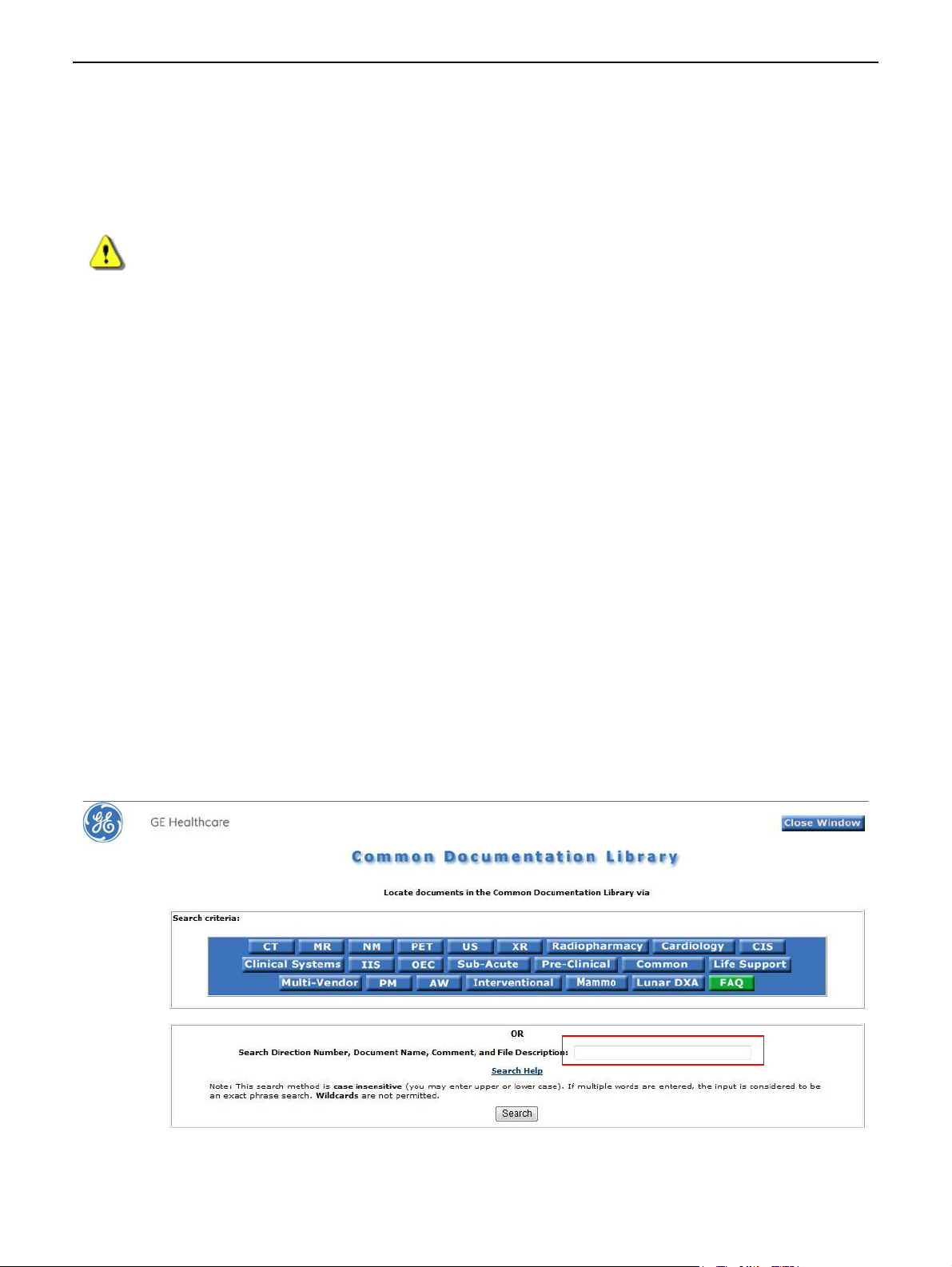
Chapter 1: Introduction
Chapter 1: Introduction
The equipment is intended for use by qualified personnel only.
CAUTION Federal law restricts this device to sale by or on the order of a physician.
This Operator Manual should be kept with the equipment and be readily available at all times. It is important for you to periodically review the procedures and safety precautions. It is important for you to read
and understand the contents of this manual before attempting to use this product.
This chapter explains the purpose and design of this Operator Manual. It provides information on the
organization, chapter format, and graphic conventions that identify the visual symbols used throughout
the manual.
How to access the electronic version of a manual on a website
The Operator Manual is available through the GE Customer Website at:
http://www3.gehealthcare.com/en/Global_Gateway
Note: A file compression/archival (zip/unzip) utility must be installed on the user’s computer.
1. Select country.
2. Click on Documentation Library under Support.
3. Select X-ray Modality and reference desired manual.
5495975-1EN Rev.9 1-1
© 2013-2017 General Electric Company. All rights reserved.
Page 23

Chapter 1: Introduction
4. Click on the underlined Filename.
5. In the next window, click [ACCEPT] to view the file.
6. From the zip file, choose your language (EN).
Technical Manual Updates
When operating or servicing GE Healthcare products, please contact your GE representative for the latest
version of product documentation. Product documentation may also be available on-line at the GE
Healthcare support documentation library.
Scope Of This Manual
This manual is intended for health care professionals trained in radiological science, and is intended to
introduce you to the system components and features. It is not intended to teach radiological science or
make any type of clinical diagnosis.
Prerequisite Skills
This guide is not intended to teach radiology. It is necessary for you to have sufficient knowledge to competently perform the various diagnostic imaging procedures within your modality. This knowledge is
gained through a variety of educational methods including clinical working experience, hospital based
programs, and as part of many college and university Radiologic Technology programs.
5495975-1EN Rev.9 1-2
© 2013-2017 General Electric Company. All rights reserved.
Page 24

Chapter 1: Introduction
Safety Information
Please refer to Chapter 2: Safety and Regulatory in this manual. The Safety chapter describes the safety
information you and the physicians must understand thoroughly before you begin to use the system.
Note that you will find additional safety information throughout your Learning and Reference Guide. If
you need additional training, seek assistance from qualified GE Healthcare personnel. The equipment is
intended for use by qualified personnel only. This guide should be kept with the equipment and be readily
available at all times. It is important for you to periodically review the procedures and safety precautions.
It is important for you to read and understand the contents of this guide before attempting to use this
product.
Safety Notices
Safety notices are used to emphasize certain safety instructions. This guide uses the international symbol
along with the danger, warning, or caution message. This section also describes the purpose of a Note.
DANGER Danger is used to identify conditions or actions for which a specific hazard is
known to exist which will cause severe personal injury, death, or substantial property damage if the instructions are ignored.
WARNING Warning is used to identify conditions or actions for which a specific hazard is
known to exist which may cause severe personal injury, death, or substantial
property damage if the instructions are ignored.
CAUTION Caution is used to identify conditions or actions for which a potential hazard may
exist which will or can cause minor personal injury or property damage if the
instructions are ignored.
IMPORTANT! An Important comment calls your attention to items that affect your workflow or image
quality but do not involve the safety of people or equipment.
Note: A Note provides additional information that is helpful to you. It may emphasize certain informa-
tion regarding special tools or techniques, items to check before proceeding, or factors to consider about a concept or task.
5495975-1EN Rev.9 1-3
© 2013-2017 General Electric Company. All rights reserved.
Page 25

Chapter 1: Introduction
Graphic Conventions and Legends
Table 1-1 describes the conventions used when working with menus, buttons, text boxes and keyboard
keys.
Table 1-1 Conventions for menus, buttons, text boxes, and keyboard keys
Example Describes
Select Marking an option in a group of check boxes or radial buttons
Choosing an option from a drop-down list
Activating a tab
Highlighting row items
Click [START EXAM] Clicking a button on a workstation screen.
Press ENTER Pressing a hard key on the keyboard.
Press CTRL+ALT+DELETE Pressing a combination of keys on the keyboard. The key that should be
clicked first is listed first.
Click and hold SHIFT Clicking and holding down a hard key on the keyboard.
In the Matrix text box,... The name of text box in which you can select or type text or the name of a
drop-down list from which you select an option.
Type DICOMAE in the... Text you enter into a text box.
Select Preferences >
Worklist.
The path of selecting option(s) in a tree structure.
5495975-1EN Rev.9 1-4
© 2013-2017 General Electric Company. All rights reserved.
Page 26
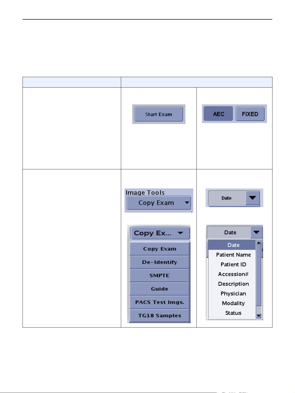
Chapter 1: Introduction
Software User Interface Controls
This manual refers to “controls” that appear on the software screens. Table 1-2 describes the most common controls that appear on the software user interface.
Table 1-2 Common software user interface controls
Control and Description Examples
Button
Screen buttons look and act like
physical buttons on equipment.
A single button performs a specific
action, such as opening a new screen
or saving settings.
A group of two or more buttons
provides a choice of settings, such as
which acquisition mode is active. The
dark blue color indicates which button
or buttons are selected.
Drop down list
Drop down lists open to reveal several
options, but only one option may be
selected at a time.
Drop down lists may be included on a
button or a text box.
The presence of a drop down list is
indicated by a down-pointing arrow on
the right side of the control.
A single button to start an
exam
A list from a button
Closed
Open
Two buttons to select the
acquisition mode
A list from a text box
Closed
Open
5495975-1EN Rev.9 1-5
© 2013-2017 General Electric Company. All rights reserved.
Page 27
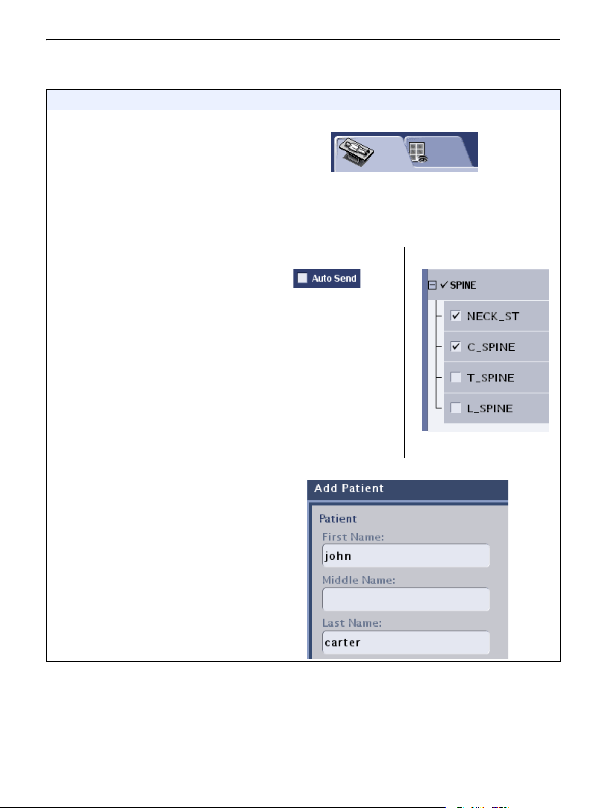
Table 1-2 Common software user interface controls
Control and Description Examples
Chapter 1: Introduction
Tab
Tabs are similar to the tabs on file
folders. They categorize related
information on a single screen.
Clicking on a tab reveals the
information related to that tab. Clicking
on another tab hides the previous
information and reveals a different set
of information.
Checkbox
Checkboxes indicate selection.
A single checkbox shows that an
option is active.
Multiple checkboxes show that several
options are selected.
A tab to move between two screens
A single checkbox Multiple checkboxes
Text box
Text boxes
Text boxes allow information to be
entered using the keyboard.
5495975-1EN Rev.9 1-6
© 2013-2017 General Electric Company. All rights reserved.
Page 28

Chapter 2: Safety and Regulatory
Chapter 2: Safety and Regulatory
This chapter explains the safety considerations, general equipment and patient related pre-
cautions, and the symbols used for the safe operation of your equipment. This chapter also
includes information about the emergency procedures.
This chapter presents the concepts necessary to successfully operate your system safely.
X-Ray Protection
X-ray equipment if not properly used may cause injury. Accordingly, the instructions herein
contained should be thoroughly read and understood by everyone who will use the
equipment before you attempt to place this equipment in operation. GE Healthcare, will be
glad to assist and cooperate in placing this equipment in use.
Although this apparatus incorporates a high degree of protection against x-radiation other
than the useful beam, no practical design of equipment can provide complete protection. Nor
can any practical design compel the operator to take adequate precautions to prevent the
possibility of any persons carelessly exposing themselves or others to radiation.
It is important that everyone having anything to do with x-radiation be properly trained and
fully acquainted with the recommendations of the National Council on Radiation Protection
and Measurements as published in NCRP Reports available from NCRP Publications, 7910
Woodmont Avenue, Room 1016, Bethesda, Maryland 20814, and of the International
Commission on Radiation Protection, and take adequate steps to protect against injury.
The equipment is sold with the understanding that GE Healthcare, its agents, and
representatives have no responsibility for injury or damage which may result from improper
use of the equipment.
Various protective material and devices are available. It is urged that such materials or
devices be used.
Indications for Use
The Optima XR646 is intended to generate digital radiographic images of the skull, spinal col-
umn, chest, abdomen, extremities, and other body parts in patients of all ages. Applications
can be performed with the patient sitting, standing, or lying in the prone or supine position
and the system is intended for use in all routine radiography exams.
The device is not intended for mammographic applications.
CAUTION Federal law restricts this device to sale by or on the order of a physician.
5495975-1EN Rev.9 2-1
© 2013-2017 General Electric Company. All rights reserved.
Page 29
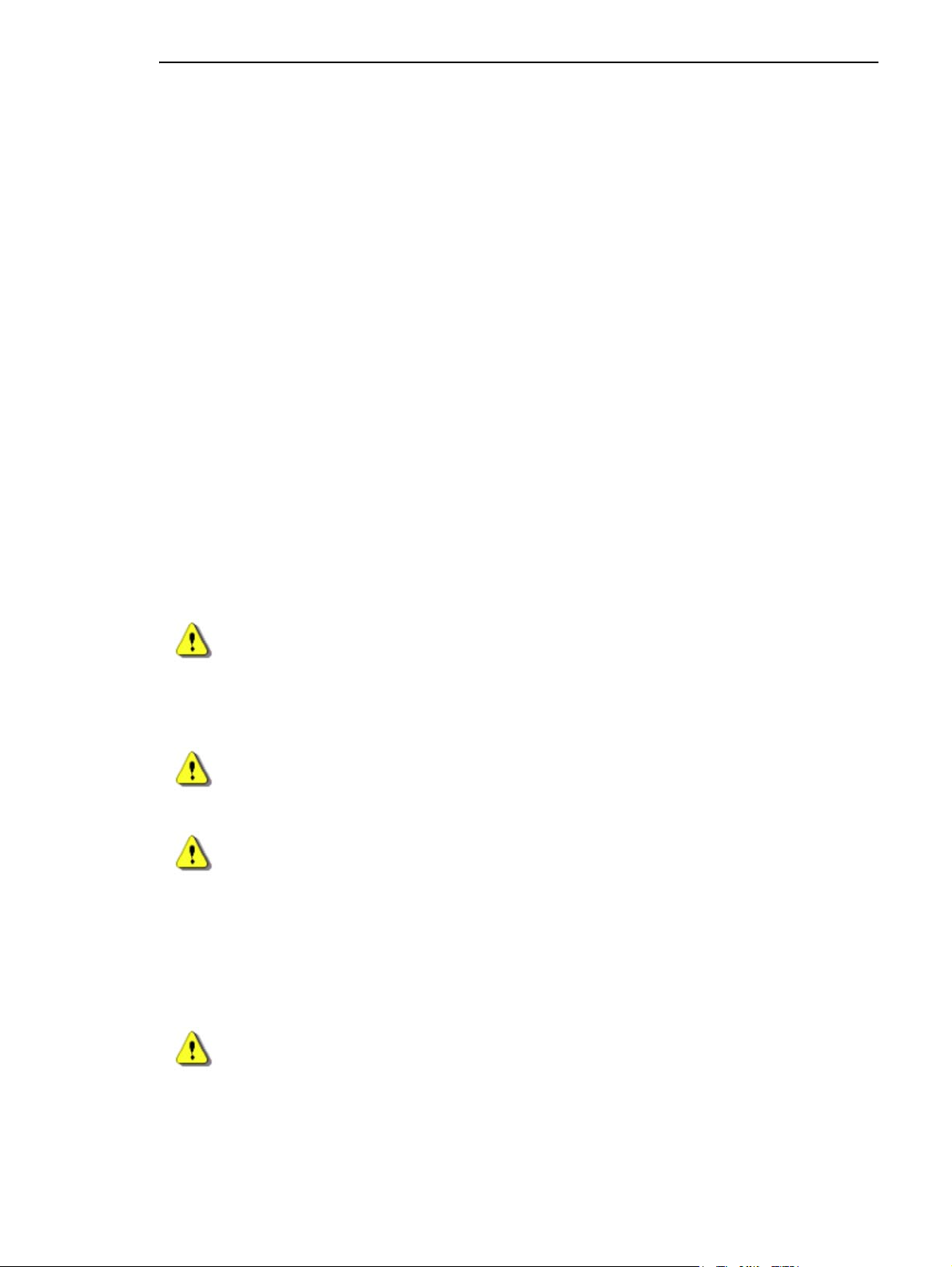
Chapter 2: Safety and Regulatory
Contraindication
None known.
Users
The targeted clinical users include qualified trained doctors, radiographers, or radiologic
technologists (RTs) working in various locations. Locations may include orthopedic clinics,
radiology imaging centers, hospital radiology departments, or hospital orthopedic depart-
ments.
Safety
The electrical wiring of the relevant rooms complies with all national and local codes, as well
as the Regulations for the electrical equipment of buildings published by the Institution of
Electrical Engineers. All assembly operations, extensions, re-adjustments, modifications, or
repairs are carried out by GE Healthcare Technologies authorized service representatives. The
equipment must be used in accordance with the instructions for use.
WARNING This X-Ray unit may be dangerous to patient and operator, unless safe
exposure factors, operating instructions and maintenance schedules
are observed.
CAUTION To be used by authorized personnel only.
WARNING Electric Shock Hazard! Do not remove covers or panels. The Acquisition
Console and cabinets contain high voltage circuits for generating and
controlling X-rays. Prevent possible electric shock by leaving covers or
panels on the equipment. There are no operator serviceable parts or
adjustments inside the cabinets. Only trained and qualified personnel
should be permitted access to the internal parts of this equipment.
CAUTION Only GEMS/GEHC validated equipment can be plugged into the outlets
in the control room wallbox. Current leakage requirements of non-validated equipment cannot be maintained with high confidence.
5495975-1EN Rev.9 2-2
© 2013-2017 General Electric Company. All rights reserved.
Page 30
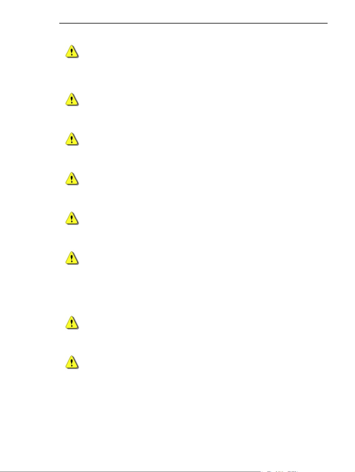
Chapter 2: Safety and Regulatory
WARNING All system components, including the OTS (Overhead Tube Suspension),
Table, Wallstand, and Operator Console must obtain their power from
the Power Distribution Unit (PDU) in the System Cabinet.
WARNING Radiographic equipment must be operated by qualified personnel and
only after sufficient training.
WARNING To avoid the risk of electric shock, this equipment must only be con-
nected to a supply mains with protective earth.
CAUTION Restrict access to the EQUIPMENT in accordance with local regulations
for RADIATION PROTECTION.
CAUTION Do not lay any object on the cabinets that would restrict air flow from
the top of the cabinet.
CAUTION Always be alert to safety when you operate this equipment. You must be
familiar enough with the equipment to recognize any malfunctions that
can be a hazard. If a malfunction occurs or a safety problem is known to
exist, do not use this equipment until qualified personnel correct the
problem.
CAUTION It is the User’s responsibility to provide the means for audio and visual
communication between the Operator and the patient.
CAUTION Use only manufacturer recommended equipment and accessories.
5495975-1EN Rev.9 2-3
© 2013-2017 General Electric Company. All rights reserved.
Page 31

Chapter 2: Safety and Regulatory
Know the Equipment
Read and understand all of the instructions in this Operator Manual before attempting to use
the product.
IEC Equipment Classifications
This product is a stationary general purpose radiographic x-ray system. The following equip-
ment classifications are applicable to this product:
Equipment classification with respect to protection from electric shock: Class I
Degree of protection from electric shock: Type B
Degree of protection against ingress of liquids: IPX0
Equipment not suitable for use in the presence of a flammable anesthetic mixture with air
or with nitrous oxide;
Mode of operation: Continuous with intermittent loading
This equipment meets the following Safety Standards:
IEC 60601-1
IEC 60601-1-1
IEC 60601-2-32
IEC 60601-2-7
IEC 60601-2-28
IEC 60601-2-54
IEC 60601-1-3
UWB (Ultra WideBand) Compliance Statement
For Japan
The frequency band used for the UWB radio function is also used for radio equipment of other
radio systems.
The use of equipment with UWB radio function shall be limited to indoors, i.e. within envi-
ronments such as houses, apartments, buildings, etc. Not approved for outdoor use. Even
when used indoors, such as at broadcast events , please confirm with the event organizer
about the use of UWB radio function as it might cause interference to broadcasting operations.
The use of equipment with UWB radio function may cause influence to radio astronomy
operations, etc. When the equipment is used near a radio astronomy observatory, contact
the following address.
In case that harmful interference to other non-UWB radio equipment (satellite earth sta-
tion antennas, 5GHz band wireless LAN, mobile phones, etc.) is caused due to the emission from the UWB radio function of the equipment, take discretionary actions, such as to
remove the UWB radio equipment from the interfering area. If interference remains,
5495975-1EN Rev.9 2-4
© 2013-2017 General Electric Company. All rights reserved.
Page 32

Chapter 2: Safety and Regulatory
promptly stop the radio emission and contact the following address: Contact us at:
______________________________________
Note: The “UWB radio function” stated in the operation manual refers to the wireless com-
munication function of the UWB radio systems.
For Canada
Canada, Industry Canada (IC) Notices
This Class B digital apparatus complies with ICES-003, Issue 4, February 7 2004 and RSS 220,
Issue 1, March 2009 and RSS GEN, Issue 3, 2010.
Operation is subject to the following two conditions:
This device may not cause interference
This device must accept any interference including interference that may cause unde-
sired operation of the device.
For United States
FCC Radiation Exposure Statement
WARNING The radiated output power of this device is far below the FCC radio fre-
quency exposure limits. Nevertheless, this device should be used in such
a manner that the potential for human contact during normal operation
is minimized. To avoid the possibility of exceeding the FCC radio frequency exposure limits, you should keep a distance of at least 20 cm
between you (or any other person in the vicinity) and the antenna.
Interference Statement
These devices comply with Part 15 of the FCC Rules. Operation of the devices is subject to the
following two conditions:
The devices may not cause harmful interference
The devices must accept any interference that may cause undesired operation.
This equipment has been tested and found to comply with the limits for a Class B digital
device, pursuant to Part 15 of the FCC Rules. These limits are designed to provide reasonable
protection against harmful interference in a residential installation. This equipment gener-
ates, uses, and can radiate radio frequency energy. If the equipment is not installed and used
in accordance with the instructions, the equipment may cause harmful interference to radio
communications. There is no guarantee, however, that such interference will not occur in a
particular installation. If this equipment does cause harmful interference to radio or television
reception (which can be determined by turning the equipment off and on), the user is encour-
aged to try to correct the interference by taking one or more of the following measures:
5495975-1EN Rev.9 2-5
© 2013-2017 General Electric Company. All rights reserved.
Page 33

Chapter 2: Safety and Regulatory
Relocate this device.
Increase the separation between the device and the receiver.
Connect the device into an outlet on a circuit different from that of other electronics.
Consult the dealer or an experienced radio technician for help.
Note: This device must be installed and used in strict accordance with the manufacturer's
instructions as described in the user documentation that comes with the product. Any
other installation or use will violate FCC Part 15 regulations.
For Australia
The frequency band used for the UWB radio function is also used for radio equipment of other
radio systems.
The use of equipment with UWB radio function shall be limited to indoors, i.e. within environ-
ments such as houses, apartments, buildings, etc. Not approved for outdoor use.
For New Zealand
The frequency band used for the UWB radio function is also used for radio equipment of other
radio systems.
1. The use of equipment with UWB radio function shall be limited to indoors, i.e. within environments such as houses, apartments, buildings, etc. Not approved for outdoor use.
2. The use of equipment with UWB radio function is not permitted onboard any aircraft.
3. Should interference occur to services licensed pursuant to a radio license or a spectrum
license, the chief executive reserves the right to require and ensure that any transmission
pursuant to this General User Radio License change frequency, reduce power, or cease
operation. Should any of these conditions present themselves, promptly stop the radio
emission and contact the address and telephone number listed in the front of this manual.
Brazil UWB Certification Information
5495975-1EN Rev.9 2-6
© 2013-2017 General Electric Company. All rights reserved.
Page 34

Figure 2-1 UWB certification for detector
Figure 2-2 UWB certification for dongle
Chapter 2: Safety and Regulatory
Wireless Regulatory Information For EU
Wireless Parts Included
The following wireless parts are included in this product:
Table 2-1
Item Name Function GE P/N
1UWB Host
Dongle
2URP Wireless
Detector
UWB host
interface to
system
workstation
Wireless
detector for
X_ray imaging
5397317-5 6 GHz - 9 GHz ≤ -41.3 dBm/MHz
5340000-7 6 GHz - 9 GHz ≤ -41.3 dBm/MHz
Accessories & Software
Frequency
Band
Transmit Power
5495975-1EN Rev.9 2-7
© 2013-2017 General Electric Company. All rights reserved.
Page 35

Chapter 2: Safety and Regulatory
The wireless parts come with the following software versions:
Table 2-2
Item Name Software / Firmware Version
1 UWB Host Dongle 5398846-4 Rev. 2
2 URP Wireless Detector 5420645 Rev. 1
EU Authorized Representative:
GE Medical Systems SCS
283 rue de la Minière
78530 BUC, FRANCE
Safety Design in Wireless Link
System will inhibit the x-ray exposure during exam if the wireless image link is poor or broken
due to low signal quality or unintended radio frequency (RF) interference. System will recover
the wireless link and lift the inhibit when the signal quality exceeds the threshold or the interference stops. Wired connection (tether mode) is provided as a backup option when the RF
environment cannot support a reliable wireless link.
Declaration of Conformity (for RED)
The wireless parts listed above are CE marked according to the provisions of the RED Directive
(2014/53/EU). GE Medical Systems LLC., here by declares that these parts are in compliance with
the essential requirements and other relevant provisions of Directive 2014/53/EU.
The Declarations of Conformity made under Directive 2014/53/EU are available on the website.
Please refer to the section How to access the electronic version of a manual on website under
chapter 1.
5495975-1EN Rev.9 2-8
© 2013-2017 General Electric Company. All rights reserved.
Page 36

Chapter 2: Safety and Regulatory
Electromagnetic Compatibility
Note: Power line anomalies or electrostatic discharges in all equipment areas may cause
the monitor image to become momentarily disrupted or to go to blank; the mouse
and/or keyboard may become inoperable or an error may be displayed on the worklist
or image viewer screens. the system may recover by itself or you may need to reboot
the system. the system may shut itself down, and will require a reboot.
CAUTION A power surge during image transmission to the workstation after
acquisition may cause the image to be lost.
WARNING When trying to fix the monitor video loss or inoperable mouse issues,
cycling the system power on/off may cause the monitor to display “can’t
open boot device error” message. if so, contact GE healthcare service.
CAUTION For continued safe use of this equipment, use only manufacturer recom-
mended accessories.
5495975-1EN Rev.9 2-9
© 2013-2017 General Electric Company. All rights reserved.
Page 37

Chapter 2: Safety and Regulatory
EMC Conformance Statement
Compliance Statement
This equipment complies with IEC 60601-1-2 Edition 2.1 (2004-11) EMC standards for medical
devices.
This equipment generates, uses, and can radiate radio frequency energy. The equipment may
cause radio frequency interference to other medical and non-medical devices and radio
communications.
To provide reasonable protection against such interference, this product complies with the
radiated emission standard limits as per CISPR11 Group1 Class A standard limits. However,
there is no guarantee that interference will not occur in a particular installation.
If this equipment is found to cause interference (which may be determined by turning the
equipment on and off), the user (or qualified service personnel) should attempt to correct the
problem by one or more of the following measure(s):
• Reorient or relocate the affected device(s)
• Increase the separation between the equipment and the affected device (see
recommended separation distances)
• Power the equipment from a source different from that of the affected device
• Consult the point of purchase or service representative for further suggestions
Use of accessories, transducers, cables and other parts other than those specified by the
manufacturer of this equipment may result in increased emissions or decreased immunity of
the equipment.
The manufacturer is not responsible for any interference caused by using other than
recommended interconnect cables or by unauthorized changes or modifications to this
equipment. Unauthorized changes or modifications could void the users' authority to operate
the equipment.
All interconnect cables to peripheral devices must be shielded and properly grounded, except
when technologically prohibited. Use of cables not properly shielded and grounded may
result in the equipment causing radio frequency interference.
The Optima XR646 systems are predominantly intended for use in non-domestic
environments, and not directly connected to the Public Mains Network that supplies buildings
used for domestic purposes.
The compatible accessories must be used within the recommended operating conditions
outlined in the operation manuals. In addition to calibration and warm-up, other devices must
be reset before and after use to ensure accurate dose measurements. Sustained exposure to
electromagnetic fields (exceeding the test conditions) may cause false measurements. Failure
to follow the recommended use may cause false measurements.
The magnetic field environment from a MRI device located nearby is a risk of interference.
5495975-1EN Rev.9 2-10
© 2013-2017 General Electric Company. All rights reserved.
Page 38

Chapter 2: Safety and Regulatory
All of the above are required to achieve the Electromagnetic Compatibility for a typical
installation of the system. Further detailed data & requirements are described in the Use
Recommendations and Installation Recommendations sections.
Compatibility Tables
This equipment complies with IEC 60601-1-2 Edition 2.1 (2004-11) EMC standards for medical
devices.
The Optima XR646 systems are suitable to be used in an electromagnetic environment, as per
the limits & recommendations described in the tables hereafter:
• Emission Compliance level & limits (Table 2-5).
• Immunity Compliance level & recommendations to maintain equipment clinical utility (see
Table 2-6 and Table 2-8).
NOTE: This system complies with above mentioned EMC standard when used with supplied
cables.If different cable lengths are required, contact a qualified service representative
for advice.
1. Electromagnetic Emission
Table 2-3 Guidance and manufacturer’s declaration – electromagnetic emissions
Guidance and manufacturer’s declaration – electromagnetic emissions
The Optima XR646 is intended for use in the electromagnetic environment specified below. The customer or the user
of The Optima XR646 should assure that it is used in such an environment.
Emissions Test Compliance Electromagnetic environment – guidance
RF emissions, CISPR 11
Group 1
RF emissions, CISPR 11 Class A
Harmonic emissions,
IEC 61000-3-2
Voltage fluctuations/
flicker emissions,
IEC 61000-3-3
Class A
Complies
The Optima XR646 uses RF energy only for its internal function.
Therefore, its RF emissions are very low and are not likely to cause
any interference in nearby electronic equipment.
The Optima XR646 is suitable for use in all establishments other than
domestic and those directly connected to the public low-voltage
power supply network that supplies buildings used for domestic
purposes.
5495975-1EN Rev.9 2-11
© 2013-2017 General Electric Company. All rights reserved.
Page 39

Chapter 2: Safety and Regulatory
2. Electromagnetic Immunity
Table 2-4 Guidance and manufacturer’s declaration – electromagnetic immunity
Guidance and manufacturer’s declaration – electromagnetic immunity
The Optima XR646 is intended for use in the electromagnetic environment specified below. The customer or the user of the Optima
XR646 should assure that it is used in such an environment.
Immunity Test IEC 60601 Test Level Compliance Level Electromagnetic Environment Guidance
Electrostatic discharge
(ESD), IEC 61000-4-2
Electrical fast transient/
burst, IEC 61000-4-4
Surge, IEC 61000-4-5
Voltage dips, short
interruptions and
voltage variations on
power supply input
lines, IEC 61000-4-11
Power frequency (50/60
Hz) magnetic field,
IEC 61000-4-8
+/− 6 kV contact.
+/− 8 kV air.
+/− 2 kV for power supply
lines.
+/− 1 kV for input/output
lines.
±1 kV differential mode
±2 kV common mode
< 5% UT (> 95% dip in UT)
for 0.5 cycle.
40% UT , (60% dip in UT)
for 5 cycles.
70% UT , (30% dip in UT)
for 25 cycles.
< 5% UT, (> 95% dip in
UT) for 5 cycles
3 A/m 3 A/m
+/− 6 kV contact.
+/− 8 kV air.
+/− 2 kV for power
supply lines.
+/− 1 kV for input/
output lines.
±1 kV differential
mode
±2 kV common
mode
< 5% UT (> 95%
dip in UT) for 0.5
cycle.
40% UT , (60% dip
in UT)for 5 cycles.
70% UT , (30% dip
in UT)for 25
cycles.
< 5% UT, (> 95%
dip in UT) for
5 cycles
Floors should be wood, concrete, or
ceramic tile. If floors are covered
with synthetic material, the relative
humidity should be at least 30%.
Mains power quality should be that
of a typical commercial or hospital
environment
Mains power quality should be that of a typical
commercial or hospital environment.
Mains power quality should be that of a typical
commercial or hospital environment. If the
user of the system requires continued
operation during power mains interruptions, it
is recommended that the system be powered
from an un-interruptible power supply or a
battery.
Power frequency magnetic fields should be at
levels characteristic of a typical location in a
typical commercial or hospital environment.
NOTE: UT is the a.c. mains voltage prior to application of the test level.
5495975-1EN Rev.9 2-12
© 2013-2017 General Electric Company. All rights reserved.
Page 40

Chapter 2: Safety and Regulatory
Table 2-5 Guidance and manufacturer’s declaration – electromagnetic immunity
Guidance and manufacturer’s declaration – electromagnetic immunity
The Optima XR646 is intended for use in the electromagnetic environment specified below. The customer or the user of The Optima
XR646 should assure that it is used in such an environment.
Immunity Test IEC 60601 Test Level Compliance Level Electromagnetic Environment Guidance
Conducted RF,
IEC 61000-4-6
Radiated RF
IEC 61000-4-3
3 Vrms,
150 kHz ~ 80 MHz
3V/m
80 MHz~2.5GHz
3Vrms
3V/m
Portable and mobile RF communications equipment
should be used no closer to any part of the Optima
XR646,
including cables, than the recommended separation
distance calculated from the equation appropriate for
the frequency of the transmitter.
Recommended Separation Distance
80 MHz to 800 MHz
800 MHz to 2.5 GHz
where, P is the maximum output power rating of the
transmitter in watts (W) according to the transmitter
manufacturer and d is the recommended separation
distance in metres (m).
Field strengths from fixed RF transmitters, as
determined by an electromagnetic site survey
should
be less than the compliance level in each frequency
b
range
.
Interference may occur in the vicinity of equipment
marked with the following symbol:
NOTE 1 At 80 MHz and 800 MHz, the higher frequency range applies.
NOTE 2 These guidelines may not apply in all situations. Electromagnetic propagation is affected by absorption and reflection from
structures, objects and people.
a Field strengths from fixed transmitters, such as base stations for radio (cellular/cordless) telephones and land mobile radios,
amateur radio, AM and FM radio broadcast and TV broadcast cannot be predicted theoretically with accuracy. To assess the
electromagnetic environment due to fixed RF transmitters, an electromagnetic site survey should be considered. If the measured field
strength in the location in which the Optima XR646 is used exceeds the applicable RF compliance level above, The Optima XR646
should be observed to verify normal operation. If abnormal performance is observed, additional measures may be necessary, such as
re-orienting or relocating the Optima XR646.
b Over the frequency range 150 kHz to 80 MHz, field strengths should be less than 3 V/m.
a
,
5495975-1EN Rev.9 2-13
© 2013-2017 General Electric Company. All rights reserved.
Page 41

Chapter 2: Safety and Regulatory
Table 2-6 Recommended separation distances between portable and mobile RF
communications equipment and the Optima XR646 – for EQUIPMENT and SYSTEMS that are
not LIFE-SUPPORTING
Recommended separation distances between portable and mobile RF communications equipment and the Optima XR646
The Optima XR646 is intended for use in an electromagnetic environment in which radiated RF disturbances are
controlled. The customer or the user of The Optima XR646 can help prevent electromagnetic interference by maintaining
a minimum distance between portable and mobile RF communications equipment (transmitters) and The Optima XR646
as recommended below, according to the maximum output power of the communications equipment.
Separation distance according to frequency of transmitter m
150 kHz to 80 MHz 80 MHz to 800 MHz 800 MHz to 2.5 GHz
Rated Maximum Output Power (P)
of Transmitter Watts (W)
0.01 0.12 0.12 0.23
0.1 0.37 0.37 0.74
1 1.17 1.17 2.33
10 3.69 3.69 7.38
100 11.67 11.67 23.33
For transmitters rated at a maximum output power not listed above, the recommended separation distance d in metres
(m) can be estimated using the equation applicable to the frequency of the transmitter, where P is the maximum output
power rating of the transmitter in watts (W) according to the transmitter manufacturer.
NOTE 1 At 80 MHz and 800 MHz, the separation distance for the higher frequency range applies.
NOTE 2 These guidelines may not apply in all situations. Electromagnetic propagation is affected by reflection from
structures, objects and people.
Radiation Safety
Always use the Optimal technical factors for each procedure to minimize X-ray exposure and
to produce the best diagnostic results. In particular, you must be thoroughly familiar with the
safety precautions before operating this system.
CAUTION There should be no people other than the patient in the exam room
during x-ray exposure. If circumstances require another person to enter
the room while x-ray exposures are planned or possible, that person
should wear a lead apron in accordance with accepted safety practices.
5495975-1EN Rev.9 2-14
© 2013-2017 General Electric Company. All rights reserved.
Page 42

Chapter 2: Safety and Regulatory
Radiation Protection
Because exposure to X-ray radiation may be damaging to health, use great care to provide
protection against exposure to the primary beam. Some of the effects of X-ray radiation are
cumulative and may extend over a period of months or years. The best safety rule for X-ray
operator is “Avoid exposure to the primary beam at all times”.
Any object in the path of the primary beam produces secondary (scattered) radiation. The
intensity of the secondary radiation is dependent upon the energy and intensity of the
primary beam and the atomic number for the object material struck by the primary beam.
Secondary radiation may be of greater intensity than that of the radiation reaching the film.
Take protective measures to safeguard against it.
An effective protective measure is the use of lead shielding. To minimize dangerous exposure,
use such items as lead screens, lead impregnated gloves, aprons, thyroid collars, etc. The lead
screen should contain a minimum of 2.0 mm of lead or equivalent and personal protective
devices (aprons, gloves, etc.) must contain a minimum of 0.25 mm of lead or equivalent. For
confirmation of the local requirements at your site, please refer to your “Local Radiation
Protection Rules” as provided by your Radiation Protection Advisor.
CAUTION While operating or servicing x-ray equipment, always keep a distance
not less than 2 meters from the focal spot and X-ray beam, protect body
and do not expose hands, wrists, arms or other parts of the body to the
primary beam.
Monitoring of Personnel
Monitoring of personnel to determine the amount of radiation to which they have been
exposed provides a valuable cross check to determine whether or not safety measures are
adequate. It may reveal inadequate or improper radiation protection practices and potentially serious radiation exposure situations.
The most effective method of determining whether or not the existing protective measures
are adequate is the use of instruments to measure the exposure. These measurements
should be taken at all locations where the operator, or any portion of the body may be
exposed. Exposure must never exceed the accepted tolerable dose.
A common method of determining whether personnel have been exposed to excessive radiation is the use of personal radiation dosimeters. These consist of X-ray sensitive film or thermoluminescent material enclosed within a holder that may be worn on the body. Even though
this device only measures the radiation which reaches the area of the body on which they are
worn, they do provide a reasonable indication of the amount of radiation received.
5495975-1EN Rev.9 2-15
© 2013-2017 General Electric Company. All rights reserved.
Page 43

Chapter 2: Safety and Regulatory
Emergency Procedures
It is not always possible to determine when some components, such as the X-ray tubes, are
nearing the end of their operating lives. These components could stop operating during a
patient examination.
CAUTION The facility must establish procedures for handling the patient in case of
the loss of radiographic imaging or other system functions during an
exam.
Emergency Devices
The system has two types of Emergency buttons:
Emergency Stop- when pressed, Lateral Table, OTS and Wallstand motions are halted, generation of X-rays is stopped. The system aborts any data acquisition in progress, and attempts
to save all data acquired prior to the abort. Use the Emergency Stop button for patient related
emergencies.
System Emergency Off Button- when pressed, the power to all system components is
removed, stopping all motion and generation of X-rays. The system aborts any acquisitions in
progress, and data obtained prior to the abort can become corrupt or lost. Use the System
Emergency OFF button for catastrophic emergencies, such as fire or earthquake.
Note: After Emergency Stop / System Emergency Off Button is enabled, there is still longitu-
dinal movement of table available. Use caution when removing patient, if necessary.
CAUTION If you press the Emergency Stop or Emergency OFF buttons during x-ray
exposure, the system will abort the data acquisition.
Emergency Stop
Note: Every operator should take a few minutes to locate the Emergency Stops on his or her
system before he or she images the first patient.
5495975-1EN Rev.9 2-16
© 2013-2017 General Electric Company. All rights reserved.
Page 44

Chapter 2: Safety and Regulatory
General Use Warnings
WARNING For continued safe use of this equipment, follow the instructions con-
tained in this Operator Manual. Study this guide carefully before using
the equipment and keep it at hand for quick reference. It may be desirable for the facility to print this manual from a standard PC to have a
hard copy available within the Radiology department.
WARNING Only qualified personnel trained in the operation of this equipment
should operate this system. Read and become familiar with all instructions in this manual before using this equipment. If further assistance is
needed, please contact GE.
WARNING It is the responsibility of the owner to make certain that only properly
trained, fully qualified personnel are authorized to operate the equipment. A list of authorized operators should be maintained.
WARNING Check for obstructions before moving the system (table, gantry or
other); do not drive the system into or onto fixed objects.
WARNING If applicable, patient connected lines, tubes, etc. shall be long enough to
allow full travel of the system and will not become pinched or pulled.
WARNING Potential Pinch Point: Use table foot pedals with care when lowering the
table. Clearance is limited next to the table side cover, and a pinch point
may exist for the operator.
WARNING It is the responsibility of the operator to ensure the safety of the patient
at all times. When the table is in use the patient should be monitored by
visual observation, use of proper patient positioning, and use of the protective devices provided.
5495975-1EN Rev.9 2-17
© 2013-2017 General Electric Company. All rights reserved.
Page 45

Chapter 2: Safety and Regulatory
CAUTION Keep the patient in full view at all times and never leave the patient
unattended while on the table.
WARNING Thoroughly check that there is no interference or possibility of collision
between the patient and other equipment.
CAUTION Please carefully monitor all equipment motions to prevent collisions.
Attention shall be drawn during operation to prevent possible injuries
that could result from collision of the power-driven equipment parts
with other moving or stationary items likely to be in the environment.
WARNING Perform periodic maintenance to ensure continued safe use of the
equipment. Follow recommended preventative maintenance schedule
as outlined in the GE Field Service Manual.
CAUTION Collision with the OTS may cause minor injury. Ensure there is no one in
the path of the OTS during positioning.
CAUTION Make sure any other accessories or materials are not located in the pri-
mary X-ray beam during exposure that could result in bad image quality.
CAUTION Some experts believe that use of any keyboard may cause serious injury
to hands, wrists, arms, neck, or back.
CAUTION Always use GEHC recommended accessories to ensure best perfor-
mance and to avoid possible hazards.
CAUTION Do not load non-system software onto the system computer.
5495975-1EN Rev.9 2-18
© 2013-2017 General Electric Company. All rights reserved.
Page 46

Chapter 2: Safety and Regulatory
CAUTION Attention to the possible adverse effect arising from materials located
in the X-ray beam.
Refer to the table below for maximum attenuation equivalent of possible materials located in
the x-ray beam.
Table 2-7 Maximum Attenuation Equivalent mm AL
Item mm Al
Image Pasting patient barrier <0.08
Non-elevating table <1.0
Non-elevating table with carbon-fiber table top <1.0
Digital elevating table with floating table top <0.7
Weight-Bearing Stand 1.08
Standard elevating table with floating table top <1.0
Manual Wallstand front panel <0.7
Standard Arm Wallstand front panel <0.7
Extended Arm Wallstand front panel <0.7
CAUTION Residual radiation hazard! Do not stand behind image receptor.
5495975-1EN Rev.9 2-19
© 2013-2017 General Electric Company. All rights reserved.
Page 47

Chapter 2: Safety and Regulatory
Laser Radiation Warnings
WARNING The collimator uses lasers to create the linear centering cross beams.
Laser radiation. Do NOT stare into beam! When you switch on the linear
laser light localizer, make sure no person looks directly into the laser to
avoid eye injuries or impaired vision. (Peak power 1 mw / wave length
540-700 nm / class II laser product.)
Figure 2-3 Collimator laser label
CAUTION Use of controls or adjustments or performance of procedures other than
those specified herein may result in hazardous radiation exposure.
5495975-1EN Rev.9 2-20
© 2013-2017 General Electric Company. All rights reserved.
Page 48

Chapter 2: Safety and Regulatory
Patient Positioning Warnings
CAUTION To avoid patient injury, always assist the patient on or off the table at
the beginning or end of an exam.
CAUTION Make sure that patient connected lines, tubes, etc. are long enough to
allow full travel of the system and will not become pinched or pulled.
WARNING During patient procedures, ensure the patient’s head, hands and feet
are completely within the tabletop area. If any portion of the patient’s
body extends over the edge of the tabletop, serious injury may result.
CAUTION The technologist must remain close to the patient when the remote con-
trol is in use.
WARNING The digital table maximum supported weight, with full tabletop func-
tionality is 320 kg (705lbs.).
Exceeding the limit may cause equipment damage or injury to the
patient.
WARNING The standard table shall have a maximum evenly distributed load capa-
bility of 250kg (552lbs).
Exceeding the limit may cause equipment damage or injury to the
patient.
CAUTION The table is designed to remain stable under normal conditions, but
when necessary for special patient loads and positioning, it will move
when sufficient force is applied. If no longitudinal movement or if abnormal patient loading is required, modifications must be made to ensure
the tabletop is locked longitudinally into position.
5495975-1EN Rev.9 2-21
© 2013-2017 General Electric Company. All rights reserved.
Page 49

Chapter 2: Safety and Regulatory
CAUTION The OTS tracks to the wallstand receptor. Use caution when moving
receptor in small room configurations. Always be sure that the patient is
clear of the OTS before selecting a wallstand configuration.
WARNING The OTS is designed to remain stable under power on conditions. When
power to the system is removed, the OTS may drift up or down.
CAUTION The wallstand lateral positioning bar is a hand rest only and is not
intended to support a person’s full weight. To avoid falls and potential
injuries, do not hang or pull on the bar.
CAUTION The operator can’t change detector connection mode before the image
is displayed on monitor after exposure.
Tabletop Motion Warnings
CAUTION When the power to the table is off, the tabletop can move freely. To
avoid injuries, monitor the tabletop movement .
WARNING Prior to raising or lowering the tabletop, ensure there are no obstruc-
tions present, above or below.
CAUTION Before the patient gets on or off the tabletop, always press the Table
Control Lock button. This momentarily blocks the foot pedal functions
and avoids injuries to the patient or damage to the equipment if a control pedal is accidentally engaged.
WARNING To avoid injury to fingers and hand do not allow the patient's or opera-
tor's fingers to be extended over the edges of the tabletop. Hands must
be kept away from table top edges at all times.
5495975-1EN Rev.9 2-22
© 2013-2017 General Electric Company. All rights reserved.
Page 50

Figure 2-4 Table pinch point
Chapter 2: Safety and Regulatory
5495975-1EN Rev.9 2-23
© 2013-2017 General Electric Company. All rights reserved.
Page 51

Chapter 2: Safety and Regulatory
Digital Detector Warnings
CAUTION Do Not Drop.
CAUTION Device weighs 4.32 kg (9.52 lbs) without battery.
CAUTION Do not use a defibrillator while patient remains in contact with detector.
CAUTION Maximum applied weight: 110kg (242 lb) standing; 160kg (352 lb) distrib-
uted.
CAUTION Operate and store the detector within the temperature range of 0 – 50º
C (32 -122°F).
Pinch Points and Crush Hazard Summary
This section lists the potential pinch points or crushing hazards that exist for various components of the system.
Table 2-8 Pinch Points and Crush Hazard Summary
Component Warning
Table
WARNING Potential Pinch Point: Use table foot pedals with care when
lowering the table. Clearance is limited next to the table side
cover, and a pinch point may exist for the operator.
Table
WARNING To avoid injury to fingers and hand do not allow the patient's
or operator's fingers to be extended over the edges of the
tabletop. Hands must be kept away from table top edges at
all times.
5495975-1EN Rev.9 2-24
© 2013-2017 General Electric Company. All rights reserved.
Page 52

Table 2-8 Pinch Points and Crush Hazard Summary
Component Warning
OTS -Column and
Tube
CAUTION Potential Pinch Point: The area where the tube connects to
the column may create a pinch point when the tube is
rotated. Operators should keep their hands on the OTS handle and keep patient’s clear while rotating the tube.
OTS - Collimator
CAUTION Always grasp the multi-leaf collimator in such a way that
neither hand can be pinched or crushed between the handles and the collimator.
Wallstand
Chapter 2: Safety and Regulatory
CAUTION Hand Crush Hazard: Keep your extremities and the patient’s
extremities away from the pinch areas and the top of the
wallstand arm when tilting the wallstand receptor.
Acquisition
Workstation
CAUTION Potential Pinch Point: The DVD/CD tray can open and close
automatically.
Symbols
This section explains the symbols used on this system and in its accompanying documents.
Special Notices
Table 2-9 Special notices
Symbol Description
Dangerous voltage. This indicates an avoidable, dangerous, high voltage hazard.
This symbol on the equipment indicates the operating instructions should be
consulted to ensure safe operation.
5495975-1EN Rev.9 2-25
© 2013-2017 General Electric Company. All rights reserved.
Page 53

Table 2-9 Special notices
Symbol Description
Hand crushing hazard. This symbol indicates that serious injury to the hand may
occur.
Follow Instructions for use
No stepping or standing on unit. The component on which the symbol appears
cannot support the weight of a person. Damage to equipment or injury may occur if
the unit is stepped or stood upon.
Maximum load. This symbol indicates that the component has a maximum weight
limit. Damage to equipment or injury may occur if the maximum weight is exceeded.
Chapter 2: Safety and Regulatory
Operating temperature. This symbol indicates that the component must be within a
minimum and maximum temperature range in order to operate. Damage to
equipment may occur if equipment is used at temperatures outside of the specified
range.
Emergency Stop Button. It’s used to immediately power down the system (including
table, OTS, wallstand, and x-ray tube) and stop image exposure.
Reference Number.
Serial Number.
Date of Manufacture.
e-IFU symbol.
The symbol indicates the instruction for use of the device is supplied in electronic
form instead of in paper form.
5495975-1EN Rev.9 2-26
© 2013-2017 General Electric Company. All rights reserved.
Page 54

Table 2-9 Special notices
Symbol Description
Gost Mark.
This mark indicates that the Device is confirmed according Russian standards.
The symbol indicates the instruction for use of Lateral positioning bar.
Chapter 2: Safety and Regulatory
X-ray Tube Operational Symbols
Table 2-10 describes the operational symbols for the system such as X-ray emissions and col-
limator locations.
Table 2-10 Operational symbols
Symbol Description
X-ray emission is used to indicate the X-ray tube head is emitting X-rays. Take
adequate precautions to prevent the possibility of any persons carelessly, unwisely,
or unknowingly exposing themselves or others to radiation.
X-ray source assembly is used to indicate a reference to an X-ray source assembly.
X-ray tube is used to indicate a reference to the X-ray tube, e.g., to mark the surface
of a grid, which is to be oriented towards the X-ray tube.
Identifies controls or indicators associated with normal rotational speed of the X-ray
anode.
Identifies controls or indicators associated with high rotational speed of the X-ray
anode.
5495975-1EN Rev.9 2-27
© 2013-2017 General Electric Company. All rights reserved.
Page 55

Table 2-10 Operational symbols
Symbol Description
Identifies controls or indicators associated with the selection of a small focal spot or
the connection for the corresponding filament .
Identifies controls or indicators associated with the selection of focal spot or the
connection for the corresponding filament . When used with the small focal spot
symbol, this symbol applies to the larger focal spot. When used with the large focal
spot symbol, this symbol applies to the smaller focal spot.
Identifies controls or indicators associated with the selection of a large focal spot or
the connection for the corresponding filament .
System Power On and Reset
Chapter 2: Safety and Regulatory
Table 2-11 describes the power controls of the system, located on the RCIM. (Refer to
Chapter 8: System Hardware Overview
more information.)
Table 2-11 Power controls
Symbol Description
The SYSTEM RESET button is used to reset the system. The button is located on
the RCIM.
The POWER ON button is used to turn on the power to the system. The button is
located on the RCIM.
-Radiology Control Interface Module (RCIM) (p. 8-6) for
5495975-1EN Rev.9 2-28
© 2013-2017 General Electric Company. All rights reserved.
Page 56

Electrical Type
Table 2-12 describes the electrical protection rating based on system type.
Table 2-12 Electrical type
Symbol Description
Type B Equipment indicates the equipment provides a particular degree of
protection against electrical shock regarding leakage current and protective
earthing per IEC60601-1.
Electrical Current
Table 2-13 describes the symbols for the different types of electrical current that may be used
on your system.
Chapter 2: Safety and Regulatory
Table 2-13 Electrical current types
Symbol Description
Alternating Current indicates the equipment is suitable for alternating current
only.
Direct Current indicates the equipment is suitable for direct current only.
Both direct and alternating currents indicate the equipment is suitable for both
direct and alternating current.
5495975-1EN Rev.9 2-29
© 2013-2017 General Electric Company. All rights reserved.
Page 57

Ground
Table 2-14 describes the different types of grounding used in your system.
Table 2-14 Ground types
Symbol Description
Functional Earth (ground) Terminal indicates a terminal directly connected to a
point of a measuring supply or control circuit or to a screening part , which is
intended to be earthed for functional purposes.
Noiseless (clean) earth (ground) identifies any terminal of a specially designed
earthing system where noise from earth of leads will not cause a malfunction of
the equipment.
Protective earth (ground) identifies any terminal which is intended for
connection of an external protective conductor to protect against electrical
shock in case of a fault.
Chapter 2: Safety and Regulatory
Frame or chassis identify the frame or chassis terminal.
Equipotentiality identifies terminals that bring the various parts of equipment or
systems to the same potential when connected together. These terminals are
not necessarily at earth (ground) potential. The value of the potential may be
indicated next to the symbol.
5495975-1EN Rev.9 2-30
© 2013-2017 General Electric Company. All rights reserved.
Page 58

Collimator
Table 2-15 describes the collimator controls and the radiation field.
Table 2-15 Collimator descriptions
Symbol Description
Control for indicating radiation field by using light.
Identifies controls for opening the collimator blades, or indicates partially or fully
open state.
Identifies controls for closing the collimator blades, or indicates closed state.
Chapter 2: Safety and Regulatory
Indicates the collimator blades are closed. The controlled blades are shown in
thicker lines.
Indicates the collimator blades are open. The controlled blades are shown in
thicker lines.
Indicates the use of laser radiation.
5495975-1EN Rev.9 2-31
© 2013-2017 General Electric Company. All rights reserved.
Page 59

Identification and Compliance Plates
Product identification labels can be found on the tops and sides of the cabinets, the rear of
monitors, and other exterior surfaces on the equipment. The types of system identification
compliance plates are located in Table 2-16.
Identification Plate and Compliance Plate Locations
Table 2-16 Identification Plate
Components Identification Plate Location
Bridge 5127305 Top of rear end cap
Chapter 2: Safety and Regulatory
Overhead Tube
Suspension
(OTS)
X-ray Tube Casing
MX100
09PS
X-ray Tube Insert .6-
1.25
12.5 degree MX100
Collimator 5234954
Workstation PC (Z420) 5843000-3
Optima XR646 System
Rating Plate
System rating plate for
Optima XR646 WSO
System Cabinet 5397035 Top of unit, on right side towards front.
5135678-3
or 5135678-4
46-155400G285 Rear of X-ray tube.
2336058 Rear of X-ray tube.
5730663
5843001-3
5502131
5730354
Rear of largest column.
Rear of collimator.
Top front of PC
Top of system cabinet
Top front of PC
Jedi 80 Rad 1T 2374870 Top of unit, on right side towards front. Also inside
system cabinet, on left side of Jedi Control Assembly.
Jedi HV Tank 2186730 Inside system cabinet, on front of Jedi HV Tank
Digital Radiographic
Table
Table Ion Chamber 5143310 Inside table detector housing.
System Label for
China
5495975-1EN Rev.9 2-32
© 2013-2017 General Electric Company. All rights reserved.
GCTBL-C2 Right side
5400528 Top of cabinet unit
Page 60

Chapter 2: Safety and Regulatory
Components Identification Plate Location
Digital Wall Stand GCWS-C1 (standard
arm)
GCEWS-C1
(extended arm)
Manual Wallstand GCMWS-C6 Left side of carriage
Standard Table GCTBL-C6 Right side
Wall Stand Ion
Chamber
Flash Pad Detector
(URP)
Tether Interface Box 5394349 Under cover, on right side.
Detector BIN 5394348 Under cover, on right side.
Flexi-DT Table
(purchasable option)
5143310 (3-cell)
5261064 (4-cell)
5340000-7 Top of unit.
5194670 On lower frame, behind right front wheel.
Left side of carriage.
Inside wall stand detector housing
NRTL Listed Label
The Nationally Recognized Testing Laboratory (NRTL) label indicates that the assembly is
listed or recognized by a nationally recognized testing laboratory (i.e. ETL, UL, CSA)
Figure 2-5 ETL Listed Label
Table Warning Labels
Digital Table Warning Labels
5495975-1EN Rev.9 2-33
© 2013-2017 General Electric Company. All rights reserved.
Page 61

Figure 2-6 Digital Table Warning Label
Chapter 2: Safety and Regulatory
Table 2-17 Digital Table warning Labels Icons
Item Description Label
1 Table pinch point label
5495975-1EN Rev.9 2-34
© 2013-2017 General Electric Company. All rights reserved.
Page 62

Table 2-17 Digital Table warning Labels Icons
Item Description Label
2 Patient load label
WARNING
1. The table can be moved vertically when the load is less than or equal to 220 kg (485 lbs),
located in the center of the tabletop end and the tabletop is positioned in the center.
Chapter 2: Safety and Regulatory
2. The table can be moved vertically when the distributed load over the table is less than or
equal to 320 kg (706 lbs) and the tabletop is positioned in the center.
3. The table cannot be moved vertically and the tabletop shall be positioned in the center
when the distributed load over the table is more than 320 kg (706 lbs) and less than or
equal to 400 kg (882 lbs).
WARNING When the patient weight exceeds 220 kg (485 lbs) then patient on/off load of
the table should only occur from the center of the front or rear side of the
table. (Maximum weight 400 kg (882 lbs))
3 Inhibition warning label
5495975-1EN Rev.9 2-35
© 2013-2017 General Electric Company. All rights reserved.
Page 63

Table 2-17 Digital Table warning Labels Icons
Item Description Label
4 Tray load label
Standard Table Warning Labels
Figure 2-7 Standard Table Warning Label
Chapter 2: Safety and Regulatory
5495975-1EN Rev.9 2-36
© 2013-2017 General Electric Company. All rights reserved.
Page 64

Table 2-18 Standard Table warning Labels Icons
Item Description Label
1 Table pinch point label
2 Patient load label
Chapter 2: Safety and Regulatory
WARNING
1. The table can be moved vertically when the load is less than or equal to 180kg (397lbs),
located in the center of the tabletop end and the tabletop is positioned in the center.
2. The table can be moved vertically when the distributed load over the table is less than or
equal to 250kg (552lbs) and the tabletop is positioned in the center.
CAUTION When the patient weight exceeds 180kg (397lbs) then patient on/off load of
the table should only occur from the center of the front or rear side of the
table (Maximum weight 250kg (552lbs)).
5495975-1EN Rev.9 2-37
© 2013-2017 General Electric Company. All rights reserved.
Page 65

Table 2-18 Standard Table warning Labels Icons
Item Description Label
3 Inhibition warning label
4 Clamp Hand label
Chapter 2: Safety and Regulatory
5Tray Symbol
OTS Label
Note: This symbol indicates that the tray moved out can’t support
the body extremities weight for X_ray exposure.
5495975-1EN Rev.9 2-38
© 2013-2017 General Electric Company. All rights reserved.
Page 66

Figure 2-8 OTS Label
Chapter 2: Safety and Regulatory
Collimator Label
Figure 2-9 Collimator Label
Figure 2-10 Collimator Caution Label
5495975-1EN Rev.9 2-39
© 2013-2017 General Electric Company. All rights reserved.
Page 67

Chapter 2: Safety and Regulatory
5495975-1EN Rev.9 2-40
© 2013-2017 General Electric Company. All rights reserved.
Page 68

Lateral Bar Label
Figure 2-11 Lateral Bar Label
Chapter 2: Safety and Regulatory
“Maximum Load Allowed: 30 kgf”
Keyboard Label
Figure 2-12 Keyboard Label
5495975-1EN Rev.9 2-41
© 2013-2017 General Electric Company. All rights reserved.
Page 69

RCIM Label
Figure 2-13 RCIM Label
Chapter 2: Safety and Regulatory
WARNING This X-Ray unit may be dangerous to the patient and operator, unless
safe exposure factors, operating instructions and maintenance schedules are observed. To be used by authorized personnel only.
UDI Label
Every Optima XR646 system has an unique marking for identification. The Unique Device
Identification (UDI) marking appears on the product label which is located on system cabinet .
UDI: Unique Device Identifier - A UDI is an unique numeric or alphanumeric identification code
assigned to medical devices by the manufacturer of the device. An unique device identification marking is applied to a Product Model that is designated as a medical device as per FDA
UDI regulation.
5495975-1EN Rev.9 2-42
© 2013-2017 General Electric Company. All rights reserved.
Page 70

Chapter 2: Safety and Regulatory
Regulatory Requirements
Note: This equipment generates, uses, and can radiate radio frequency energy. The equip-
ment may cause radio frequency interference to other medical and non-medical
devices and radio communications. To provide reasonable protection against such
interference, this product complies with emission limits for Group 1 Class A Medical
Devices as stated in EN 60601-1-2. However, there is no guarantee that interference
will not occur in a particular installation.
Note: If this equipment is found to cause interference (which may be determined by switch-
ing the equipment on and off), you (or qualified service personnel) should attempt to
correct the problem using one or more of the following measures:
- Reorient or relocate the affected devices.
- Increase the space separating the equipment and the affected device.
- Power the equipment from a source different from that of the affected device.
- Consult the point of purchase or the service representative for further suggestions.
Note: The manufacturer is not responsible for any interference caused either by the use of
interconnect cables other than those recommended or by unauthorized changes or
modifications to this equipment. Unauthorized changes or modifications could void
the user’s authority to operate the equipment.
Note: To comply with the regulations applicable to an electromagnetic interface for a Group
1 Class A Medical Device, all interconnect cables to peripheral devices must be
shielded and properly grounded. The use of improperly shielded and grounded cables
may result in the equipment causing radio frequency interference in violation of the
European Union Medical Device directive and Federal Communications Commission
regulations.
Note: Do not use devices which intentionally transmit radio frequency (RF) signals (cellular
phones, transceivers, or radio controlled products) in the vicinity of this equipment, as
it may cause performance outside the published specifications.
Keep the power to these type devices turned off when near the equipment.
The medical staff in charge of this equipment is required to instruct technologists, patients,
and other people who may be around this equipment, to fully comply with the above requirement.
This product complies with the following requirements:
Council Directive 93/42/EEC concerning medical devices when it bears the following CE marking of conformity:
Figure 2-14 CE mark label
5495975-1EN Rev.9 2-43
© 2013-2017 General Electric Company. All rights reserved.
Page 71

Chapter 2: Safety and Regulatory
Disposal of Waste
This symbol indicates that the waste of electrical and electronic equipment must not be disposed as unsorted municipal waste and must be collected separately. Please contact an
authorized representative of the manufacturer for information concerning the decommissioning of your equipment.
Figure 2-15 Disposal of waste symbol
Battery Disposal
The separate collection symbol is affixed to a battery, or its packaging, to advise you that the
battery must be recycled or disposed of in accordance with local or country laws. The letters
below the separate collection symbol indicate whether certain elements (Pb=Lead, Cd=Cadmium, Hg=Mercury) are contained in the battery. To minimize potential effects on the environment and human health, it is important that all marked batteries that you remove from the
product are properly recycled or disposed.
For information on how the battery may be safely removed from the device, please consult
the service manual or equipment instructions. Information on the potential effects on the
environment and human health of the substances used in batteries is available at this url:
http://www.gehealthcare.com/euen/weee-recycling/index.html
Figure 2-16 Battery Disposal symbol
5495975-1EN Rev.9 2-44
© 2013-2017 General Electric Company. All rights reserved.
Page 72

Chapter 2: Safety and Regulatory
Pollution Control Label
The following product pollution control information is provided according to SJ/T11364-2006
Marking for Control of Pollution caused by Electronic Information Products.
Figure 2-17 Pollution control symbol
This symbol indicates the product contains hazardous materials in excess of the limits established by the Chinese standard SJ/T11363-2006 Requirements for Concentration Limits for
Certain Hazardous Substances in Electronic Information Products. The number in the symbol
is the Environment-friendly Use Period (EFUP), which indicates the period during which the
toxic or hazardous substances or elements contained in electronic information products will
not leak or mutate under normal operating conditions so that the use of such electronic information products will not result in any severe environmental pollution, any bodily injury or
damage to any assets. The unit of the period is Year.
In order to maintain the declared EFUP, the product shall be operated normally according to
the instructions and environmental conditions as defined in the product manual, and periodic
maintenance schedules specified in Product Maintenance Procedures shall be followed
strictly.
Consumables or certain parts may have their own label with an EFUP value less than the
product. Periodic replacement of those consumables or parts to maintain the declared EFUP
shall be done in accordance with the Product Maintenance Procedures.
This product must not be disposed of as unsorted municipal waste, and must be collected
separately and handled properly after decommissioning.
5495975-1EN Rev.9 2-45
© 2013-2017 General Electric Company. All rights reserved.
Page 73

Dose Chart
Use Table 2-19 to compare film speed to dose values.
Table 2-19 Dose Chart
Chapter 2: Safety and Regulatory
Expected receptor Default Dose (µGy) at 80 kVp
is less than:
16.00 100
12.90 125
10.00 160
8.00 200
6.25 250
5.00 320
4.00 400
3.20 500
2.50 640
2.00 800
1.60 1000
CAUTION Use the largest possible focal spot-to-skin distance to keep the patient
absorbed dose as small as possible.
Equivalent Film Speed
CAUTION If no technical factors are present in the system for any view, the default
settings are:
– kV = 40
– ma = 25
– mAs = 0.25
– SID = 100cm
–Grid = In
These values are placeholders only. No exposures should be made until
the user selects values appropriate for the patient size.
5495975-1EN Rev.9 2-46
© 2013-2017 General Electric Company. All rights reserved.
Page 74

Chapter 2: Safety and Regulatory
Fi
F
I
Tub
mAs
kVp
ltration
SID
OV size
nput
e angle
No
m
Ca
inal Dose
lculation
C
Multi
p
im
a
Dista
n
alculation
lication of
e area
ce Scaling
P
a
D
o
tient Entran
c
se Area Pro
d
Output
e Dose
uct
X-ray Source Assembly Filtration
The x-ray source assembly is comprised of the x-ray tube and collimator. Together they provide permanent, non-removable filtration of 2.7 mm aluminum equivalent @ 71 kVp. Additional collimator filtration is user selectable. Refer to Chapter 8: System Hardware Overview
-
Multi-Leaf Collimator (p. 8-26) for detailed information.
CAUTION This system is designed to be used with only the GE MX100 tube and col-
limator model number 5234954. Replacement of either of these components with different types may render the system non-compliant to
applicable radiation safety standards and regulations.
Dose/DAP Indication
The Dose/DAP value is predicted by calculation. They are displayed on the image viewer for
each exposure. The Dose value is calculated at the position of patient entrance.
Figure 2-18 Block diagram for Dose/DAP calculation:
The nominal Dose is calculated at the calibrated distance, based on exposure techniques,
such as mAs, kVp and additional filtration. The final patient entrance dose is got by correcting
with SID and tube angle and the preset patient thickness.
DAP is got by multiplying Patient entrance dose and the image area at that distance.
Increase/decrease of the kVp, mAs, will lead to increase/decrease of Dose and DAP
Increase/decrease of the SID only, will lead to decrease/increase of Dose and DAP
Increase/decrease of the FOV only, will lead to increase/decrease of DAP, but Dose will not
change.
5495975-1EN Rev.9 2-47
© 2013-2017 General Electric Company. All rights reserved.
Page 75

Chapter 2: Safety and Regulatory
Environmental protection
With the disposal of waste products, residues and equipment accessories that are out of their
expected service life, to avoid the impact of environment, please comply with local statute or
call GE Service.
5495975-1EN Rev.9 2-48
© 2013-2017 General Electric Company. All rights reserved.
Page 76

This page intentionally left blank.
Chapter 2: Safety and Regulatory
5495975-1EN Rev.9 2-49
© 2013-2017 General Electric Company. All rights reserved.
Page 77

Chapter 3: Pediatrics and small patients
Chapter 3: Pediatrics and small patients
GE Healthcare strongly suggests reducing radiation dose to As Low As Reasonably Achievable (ALARA) in
all patients, especially pediatric and small patients, whenever it is determined that an x-ray is necessary.
X-ray is an extremely valuable tool for diagnosing injury and disease, but its use is not without risk. This
section discusses the importance of minimizing the radiation dose in children and small adults consistent
with ALARA principles.
Topics covered include:
• Pediatric Use
• Optimize Pediatric Protocols for your facility
• What Do I Need to Know About?
Pediatric Use
Radiation exposure is a concern in both adults and children. However, children are more sensitive to
radiation. Using the same exposure parameters on a child as used on an adult may result in larger doses
to the child. X-ray settings can be adjusted to reduce dose significantly while maintaining diagnostic
image quality.
Optimize Pediatric Protocols for your facility
The protocols supplied with the system represent examples for procedures commonly conducted in
radiography. Based on the needs of a particular practice, these protocols may be modified to optimize
factors such as image quality or dose reduction.
Work with your team of Radiologists, Medical Physicists and Technologists to evaluate techniques that
may reduce radiation dose and provide adequate diagnostic information. In addition to the
recommended protocols installed on your system and suggestions in this guide, the following websites
offer excellent sources of additional information on how to optimize protocols:
• American College of Radiology (ACR): www.acr.org
• Society of Pediatric Radiology (SPR): www.pedrad.org
• National Cancer Institute (NCI): www.nci.nih.gov/aboutnci
•Image Gently: www.imagegently.org
• US Food and Drug Administration (FDA): www.fda.gov
5495975-1EN Rev.9 3-1
© 2013-2017 General Electric Company. All rights reserved.
Page 78

Chapter 3: Pediatrics and small patients
What Do I Need to Know About?
This section presents the concepts necessary to understand Pediatric x-ray imaging. The concepts you
need to understand are:
• Radiation Exposure Sensitivity
• Suggestions for Minimizing Unnecessary Dose
• Guidelines for Adjusting Individual Exposure Parameters by patient
• Patient Dose Reporting
• Dose Index Reporting Considerations
• Protocol Database Edit
Everyone shares the responsibility of minimizing pediatrics dose. There are several steps that can be
taken to reduce the amount of radiation that pediatrics and small patients receive from x-ray
examinations.
Radiation Exposure Sensitivity
Radiation exposure is a concern in all people of all ages, however, pediatrics are more sensitive to
radiation exposure. Radiation risk is higher in the young as they have more rapidly dividing cells than
adults. The younger the patient, the more sensitive they are.
Suggestions for Minimizing Unnecessary Dose
• Image the Anatomical Region Indicated (Collimation): Collimation and anatomical coverage should
be carefully considered prior to each exposure. Follow your facility imaging guidelines to determine
appropriate collimation.
• Properly Center All Patients: In addition to collimation, centering of intended anatomy should be
considered. This is especially true when utilizing AEC/ion chambers. Improper centering over ion
chambers may cause more or less than the desired dose which may lead to overexposure or repeat
exposure.
• Check Technical Factors Before Exposure: Review technical display carefully before making an
exposure to verify selected and intended technique are the same. Pay particular attention to
placement of decimal point in display of numerical values.
• Use Pediatric Positioning Accessories: Approved Pediatric positioning accessories are often useful for
certain patients and exams. These may be helpful in decreasing motion that may contribute to
repeat exposure. Understand your facilities guidelines when implementing these devices.
• Protective Apparel/Barriers/Shielding: When applicable, utilize proper protective measures as they
comply with your facility guidelines.
• Consider Patient Radiation Safety Protocols: Ensure understanding and conformance of Patient
Radiation/Protection Safety and ALARA principles as required by your facility. This includes patient
shielding to reduce exposure to unintended areas.
5495975-1EN Rev.9 3-2
© 2013-2017 General Electric Company. All rights reserved.
Page 79

Chapter 3: Pediatrics and small patients
Guidelines for Adjusting Individual Exposure Parameters by patient
Adjust Parameters: The single most important thing you can do is to always use pediatric protocols to
avoid over exposure. Protocols based on patient size are installed on the system. There are six patient
sizes available: Adult and Pediatric; Small, Medium and Large Patient Size. These protocols should be
considered a baseline. GE strongly recommends that you work with your Radiologist and Physicist to
determine the lowest possible dose for the desired image quality.
Figure 3-1 Patient Size
Once patient size is selected, further adjustments to kVp, MAS, Filtration and Grid can be made to further
minimize patient dose.
Automatic - Exposure or Fixed Exposure: Consideration should be made when utilizing Automatic
Exposure (AEC) or Fixed Exposure. Each protocol on your system has been installed with a preset method
of exposure; however, GE recommends reviewing each protocol and utilizing the method that will allow
for the lowest possible dose.
Use of ion chambers for AEC require careful positioning of patient and should be considered prior to
making an exposure. GE recommends that each facility work with your Radiologist and Physicist. Refer to
Image Acquisition Chapter located in this operator manual for more information on AEC chambers and
sensing areas.
Figure 3-2 Ion Chamber
5495975-1EN Rev.9 3-3
© 2013-2017 General Electric Company. All rights reserved.
Page 80

Chapter 3: Pediatrics and small patients
Patient Dose Reporting
Estimates of patient dose are calculated after each acquisition and displayed (optionally) as part of the
image annotations. The information is also stored in the DICOM header of each image. Reference Patient
Dose Reporting in this operator manual for more information.
– Dose Index Reporting Consideration
Your system is provided with a Dose Index visual indicator. This indicator is displayed as an amount of
exposure received by the receptor. These are estimated ranges and can be changed as technical factors
are changed. Reference the DEI/DI section of this operator manual for more information.
Protocol Database Edit
In collaboration with your Radiologist and Physicist, protocol techniques can be changes as a default on
your system. This should not replace observing the technical acquisition screen carefully prior to each
exposure, but can assist in displaying an appropriate range of techniques for selected pediatric size.
Further changes to techniques are recommended based on each individual patient.
Refer to the Protocol Database Edit chapter in this operator manual to ensure proper editing. Always
complete a protocol database back up. Should any changes occur to your system, the database back up
may be retrieved with saved protocols.
For questions or further information, contact your local GE Healthcare representative.
5495975-1EN Rev.9 3-4
© 2013-2017 General Electric Company. All rights reserved.
Page 81

Chapter 4: General Information
Chapter 4: General Information
This chapter explains some of the basic operations and features of the system such as how to start up
and shutdown the system software, how to login and log off, and how to view system status and messages.
Refer to Chapter 8: System Hardware Overview
for information about identifying system components.
5495975-1EN Rev.9 4-1
© 2013-2017 General Electric Company. All rights reserved.
Page 82

Chapter 4: General Information
System Start Up and Shutdown
This section describes the procedure for starting up and shutting down the system.
The system should remain on at all times for optimal performance. However, a controlled system shut
down and start up should be performed once a week as part of routine QAP. Refer to Chapter 14: Quality
Assurance and Maintenance for more information.
If the receptor loses power for 30 minutes or more, reset the system and warm the receptor with active
power in “on” state for at least 30 minutes. Refer to System Emergency OFF Buttons
information.
Start Up
1. Press the Power On button on the RCIM [Radiology Control Interface Module].
Figure 4-1 Power button on RCIM
(p. 4-10) for more
2. Wait a few minutes until the entire system is powered.
The system powers up automatically.
If enabled, the Login screen appears on the monitor when the system is ready. Refer to Login and
Log off (p. 4-4) for more information.
If Login is not enabled, the Worklist appears on the monitor when the system is ready. Refer to
Chapter 9: Worklist
3. Wait for the detector to boot . This takes approximately 30 seconds.
A message in the system status area will appear: “Detector Boot is in progress. Please wait 29 sec-
onds for the detector boot to complete.”
The system is ready when the detector boot message disappears.
for more information.
5495975-1EN Rev.9 4-2
© 2013-2017 General Electric Company. All rights reserved.
Page 83

Chapter 4: General Information
Shutdown
CAUTION Do not to turn the system off if the tube fan is running. Wait for the tube to cool
and for the fan to stop.
1. Close all current exams. (Refer to Chapter 10: Image Acquisition-End Exam (p. 10-31) for more information.)
2. Click the [UTILITY] button at the top of the Worklist screen.
Figure 4-2 Utility button
3. Select System on the Utilities screen.
Figure 4-3 Utilities – System screen
4. Click [SHUTDOWN].
A message appears: “The system will be shut down. NOTE: Please allow for the tube fan speed to
slow (if running high) before shutting down system.”
5. Click [YES] to proceed with shut down.
The system powers off and the monitors go blank.
[CANCEL] stops the system from shutting down and returns you to the Utilities screen.
5495975-1EN Rev.9 4-3
© 2013-2017 General Electric Company. All rights reserved.
Page 84

Chapter 4: General Information
Note: Wait approximately 30 seconds after a shutdown to power up the system.
Login and Log off
The following sections apply if the system is configured to use the Login feature in the Utilities User Interface, Refer to Appendix A: Login Administration
Standard Login
The Login screen (Figure 4-4) appears when the system is started, reset, and after a user logs off. The system may also be configured to display the Login screen if the system has been inactive for a specified
period of time (inactivity timeout).
Figure 4-4 Example login screen.
for information on administering the login function.
Follow this process to login to the system.
1. Start up the system or log off the previous user.
The Login screen appears.
2. Enter your Login Name.
3. Enter your Password.
4. Click [LOGIN].
The Worklist appears. Refer to Chapter 9: Worklist
5495975-1EN Rev.9 4-4
© 2013-2017 General Electric Company. All rights reserved.
for more information.
Page 85

Chapter 4: General Information
Invalid Password Message
Your Password must be entered correctly for you to log in. If the password you entered is not the correct
password for the selected User name, an error message will appear in the top portion of the Login
screen: “Logon Failed. Check that the CAPS LOCK Key is off. For assistance, contact your system administrator.“
1. Make sure that the correct Login Name is displayed in the field. Depending on the configuration, the
Login Name may be case sensitive. That is, “aBc” is not the same Login Name as “Abc.”
2. Retype your Password carefully. Your password is case sensitive; that is, “xYz” is not the same password as “Xyz.”
3. Click [LOGIN].
Contact your technical support group or system administrator if you still are not able to login.
Emergency Login
Emergency Login is a HIPAA required function to allow quick access to medical systems in the event of an
emergency. Depending on the system’s configuration, this option may not be available. Refer to
Appendix A: Login Administration
to configure the Emergency Login function.
Emergency Login will allow exposures, but does not allow connection to HIS/RIS or PACS hosts.
CAUTION The Emergency Login function should NOT be used when there is time to login nor-
mally, when there is time to receive assistance from technical support, or if there
is no emergency situation.
1. Click [EMERGENCY LOGIN].
You are prompted to enter your name. Enter your name and click [LOGIN]
2. The Worklist screen appears. Refer to Chapter 9: Worklist
5495975-1EN Rev.9 4-5
© 2013-2017 General Electric Company. All rights reserved.
for more information.
Page 86

Chapter 4: General Information
Inactivity Time out (Screen Saver)
Depending on the system’s configuration, the system may show the Login screen after a specified period
of inactivity. The Login screen acts as a screen saver, covering displayed information to protect patient
privacy.
The administrator configures if the system will time out and how long the system must be inactive before
the Login screen appears. Refer to Appendix A: Login Administration
function.
To access the system screens, follow the Standard Login or Emergency Login process described above.
to configure the inactivity time out
Log Off
1. Close, suspend, or discontinue any open exams, if necessary. (Refer to Chapter 10: Image Acquisition-
End Exam (p. 10-31) for more information.)
2. Close the Image Viewer, if necessary.
3. Click [LOGOFF] at the top of the Worklist or Image Management screen.
Or open the Utility screen, go to System and click [LOGOFF] (Figure 4-5).
Figure 4-5 Utilities screen logoff button
A message appears: “Do you really want to log off?”
4. Click [OK].
The Login screen appears.
[CANCEL] closes the screen and returns you to the last screen.
5495975-1EN Rev.9 4-6
© 2013-2017 General Electric Company. All rights reserved.
Page 87

Chapter 4: General Information
System Interlocks
Your system has a series of interlocks that can place the system in an exposure hold state. When certain
conditions exist outside of normal operation, the red LED on the user interface becomes lit.
Grid Interlock
If the Grid interlock is activated, the Exposure Hold icon will appear on the OTS user interface and at the
Acquisition workstation screens. Select the Exposure Hold icon for detailed description on the inhibit condition.
Automatic Exposure Control (AEC) Interlock
If the tube is not centered laterally and longitudinally on the center ion chamber, the Exposure Hold icon
may appear on the OTS user interface and at the Acquisition workstation screens. If the tube is not centered laterally and longitudinally on the center ion chamber, the Exposure Hold icon for detailed description on the inhibit condition.
OTS Position Interlock
When the X-ray field is outside of the receptor area and/or not in lateral or SID detents, the Exposure
Hold icon will appear on the OTS user interface and at the Acquisition workstation screens. Select the
Exposure Hold icon for detailed description on the inhibit condition.
Note: This interlock is no longer active when the tube angle is > +/- 10 degrees.
Tube Pivot Interlock
The Tube Pivot interlock LED illuminates when the tube pivot must be rotated to 0 degrees (normal position).
Free Cassette Interlock
When in Free Cassette mode (using CR or film for Table top receptor) the detector drawer in the table
must be pulled out to release the optical sensor that recognizes that the cassette is in place, or the detector must be removed completely. If the Free Cassette mode is selected without releasing this optical sensor, the Exposure Hold icon will appear on the OTS user interface and at the Acquisition workstation
screens. Select the Exposure Hold icon for detailed description on the inhibit condition.
Table Finger Pinch Interlock
The table is equipped with optical sensors beneath the edges of the table between the emergency stop
button and table lock button on each side. The sensor stops lateral and longitudinal movement of the
table top if fingers or other objects are beneath the table edges, as shown in Figure 4-6.
5495975-1EN Rev.9 4-7
© 2013-2017 General Electric Company. All rights reserved.
Page 88

Chapter 4: General Information
Figure 4-6 Finger pinch lock trigger
The system will beep and a message will appear on the Acquisition Workstation informing you of the
table lock. Exposures will be inhibited until the lock is resolved.
To unlock the table top:
1. Release the Table top positioning foot pedal (if necessary).
Figure 4-7 Table top positioning foot pedal
2. Remove hands, fingers, or other object from under the table edge.
3. Press the table top positioning foot pedal (Figure 4-7) two consecutive times (“double-tap”).
4. Hold the foot pedal down and position the table top.
5495975-1EN Rev.9 4-8
© 2013-2017 General Electric Company. All rights reserved.
Page 89

Chapter 4: General Information
Emergency Stop
Emergency stop immediately powers down the system—including table, OTS, wallstand, and x-ray tube—
and stops image exposure. The digital table and RCIM are equipped with Emergency Stop buttons
(Figure 4-8).
To engage: Press the button.
To release: Turn (RCIM) or pull (table) the e-stop button to release.
Figure 4-8 Emergency Stop buttons
RCIM
Digital Table Standard Table
Use this procedure to perform an emergency stop and to reset the Emergency Stop button.
1. In an emergency situation, press the Emergency Stop button in with force.
2. Resolve the emergency situation.
CAUTION For Digital table, when the Emergency Stop button has been activated, the table
will move longitudinally only. The table is not locked into position. Exercise
extreme caution with your patient when this happens.
3. When normal conditions are confirmed, turn (RCIM) or pull (table) the e-stop button to reset.
The system will power up automatically.
Note: If turn the e-stop button on RCIM to reset, turn the button clockwise (indicated by the arrows on
the button) until it stops, then release.
5495975-1EN Rev.9 4-9
© 2013-2017 General Electric Company. All rights reserved.
Page 90

Chapter 4: General Information
Figure 4-9 Emergency Stop screen
System Emergency OFF Buttons
In the event of a fire, flood, earthquake, or any other catastrophic emergency, all power to the system
should be turned off. Pressing the System Emergency OFF button immediately removes all power to the
system by removing power to the System Cabinet. Because the system has no time to save data, or shutdown in an orderly fashion, pressing the System Emergency OFF button can corrupt system files or result
in loss of patient data.
The facility designer determines the quantity and locations of the Emergency OFF buttons. GE recommends placing at least one Emergency OFF button near the doorway of every room in the system scan
suite. Ask your supervisor to show you the location of all the Emergency OFF buttons in the system suite.
Follow facility guidelines to report an emergency. Press the System Emergency OFF button (red, circular
button located on the wall) in the event of a catastrophic emergency, such as fire or earthquake.
System Reset
Should the system require a reset, this may take up to 3 minutes to complete.
Note: The system will not be available for acquiring images during the reset cycle.
1. If possible, close, suspend, or discontinue any open exams. (Refer to Chapter 10: Image Acquisition
End Exam (p. 10-31) for more information.)
2. If possible, log off the system.
3. Press and hold the RESET button on the RCIM until you hear the beep or the monitor screen goes
black with white text . Release the button and wait until the Login or Worklist screen appears.
-
5495975-1EN Rev.9 4-10
© 2013-2017 General Electric Company. All rights reserved.
Page 91

Chapter 4: General Information
Figure 4-10 Reset button on the RCIM
4. Release the button and wait until the Login or Worklist screen appears.
As the system resets, various screens will appear on the monitor. This is normal.
The system will auto-start and either the Login screen or Worklist screen will appear (depending on
how your system is configured) when the system is ready. Refer to Start Up
mation.
(p. 4-2) for more infor-
Tube Warm Up
To extend the life of the tube, tube warm up should be done if no exposures have occurred within two
hours. A warning icon will display when tube warm up is needed.
CAUTION Initiating an exposure when the X-ray tube is cold may damage the tube target.
Click [WARM TUBE] (Figure 4-11) at any time to see the tube heat status.
Figure 4-11 Warm Tube button
Figure 4-12 Warm Tube screen
5495975-1EN Rev.9 4-11
© 2013-2017 General Electric Company. All rights reserved.
Page 92

Chapter 4: General Information
CAUTION Ensure no detector is in X-Ray path
Table 4-1 Warm Tube functions
Function Description
Tube Heat Status Shows the current status of the tube.
Warm up needed in __ Min Shows how many minutes until the tube needs to be warmed.
A time of 0 minutes means that the tube must be warmed immediately.
Exposure Required Shows the number of exposures required to warm the tube.
Soak Time Remaining Shows how many seconds of soak time remain.
Exposure Hold Lists any inhibits to making an exposure or warming the tube.
kV Shows the kV of the current exposure.
mA Shows the mA of the current exposure.
mAs Shows the mAs of the current exposure.
mSec Shows the mSec of the current exposure.
[CLOSE] Closes the Warm Tube screen.
Follow this process to warm up the tube.
CAUTION X-rays are generated during tube warm up. Use proper radiation practices at all
times.
1. Check the room to make sure it is clear of other personnel before making X-ray exposures.
2. Click [WARM TUBE] on the Worklist screen.
Note: Because the tube warming procedure produces x-rays, it cannot be performed when an exam is
open. If the tube must be warmed before the exam can begin, suspend the exam and remove the
patient and any others from the room before warming the tube. Refer to Chapter 10: Image
Acquisition-End Exam (p. 10-31) for more information.
3. Correct any exposure holds.
CAUTION Exposures should not be made on any detector during tube warm-up. The system
will attempt to mis-align the tube and the detector, but you may need to manually
move the tube so that the detector is not exposed during the warm-up sequence.
Pay close attention to system message information for instructions to manually
move the detector. Exposing the detector may cause a “burned in” image artifact.
5495975-1EN Rev.9 4-12
© 2013-2017 General Electric Company. All rights reserved.
Page 93

Chapter 4: General Information
4. Press the Hand-switch Prep/Expose button to the Expose position and hold until the Exposures
Required reads “0”.
Note: The exposure hand switch should be held for 18 consecutive exposures to ensure proper tube
warm up. The Exposures Required number counts down as each exposure is made.
5. Wait until the Soak Time reads “0”.
6. Click [CLOSE] to finish tube warm up.
You may now continue taking x-rays.
Identification of Radiographs
As in any Radiography procedure, identification of images is important to ensure proper anatomical reference. Users should take extra care to ensure their image marker/identification placement prior to
exposure is optimal and included in the field of view.
All users are recommended to follow their Institution’s guidelines for image marker implementation.
Note: Use of electronic/annotated markers as part of post processing is not recommended as a pri-
mary method of image identification because of potential user error in identifying anatomical
regions.
Image Markers
Image markers (e.g. lead markers) are commonly used in identifying radiographs. If image markers are
placed in regions of direct radiation (saturation), there is a possibility they can be processed out of the
image during image processing. Saturated areas beyond the anatomy are no longer part of the final
image. This is most likely to occur to over exposed images.
In cases where image markers become processed out of the image, users may manually adjust the electronic shutters to include the marker on the final image.
Note: This may cause Detector Exposure Index (DI) result to change. For instructions on how to adjust
the electronic shutter, please refer to Chapter 11: Image Viewer
CAUTION Exercise care when placing image markers to guarantee their presence in the final
image. Every attempt must be made to assure markers are not located in regions
of direct radiation, but are located in regions where some patient attenuation of
radiation is present without obstructing the anatomical information of interest.
.
5495975-1EN Rev.9 4-13
© 2013-2017 General Electric Company. All rights reserved.
Page 94

Chapter 4: General Information
iLinq
iLinq is a system feature, if configured, which allows access to remote service and clinical applications
support.
The iLinq system lets authorized Service Engineers and Applications Specialists, located at GE Healthcare’ Service Support Centers, access X-ray systems (with your permission) to provide the following services:
Faster Emergency Service response
Customer Applications training/support
System troubleshooting and diagnostics
Accumulate system information for failure analysis, resolution and prediction to assist in maintaining
optimal X-ray system performance
5495975-1EN Rev.9 4-14
© 2013-2017 General Electric Company. All rights reserved.
Page 95

Figure 4-13 iLinq Main Screen
Chapter 4: General Information
5495975-1EN Rev.9 4-15
© 2013-2017 General Electric Company. All rights reserved.
Page 96

Chapter 4: General Information
Table 4-2 iLinq Screen functions
Function Description
Contact GE The Contact GE Form allows the electronic submission of a service request or
applications question directly to the Online Center.
Figure 4-14 shows the screen you use to report a problem with your system,
using the iLinq system.
Settings The Settings page allows you to enter the default contact information that will
display on the Contact GE Form. This includes a list of Contacts, System ID,
Phone Number.
Messages Receives messages from the Online Center.
Tip Virtual Assist A tool which offers live Clinical Applications training support. Contact your
Applications Specialist or Sales Representative for more information about this
feature.
Close To exit the iLinq feature, click on CLOSE in the upper right corner of your
screen. This will return you to the Optima XR646 system.
5495975-1EN Rev.9 4-16
© 2013-2017 General Electric Company. All rights reserved.
Page 97

Figure 4-14 iLinq Contact GE screen
Chapter 4: General Information
Use this procedure to connect to the iLinq system when you need to report a problem with your system.
1. Click the [iLinq] icon on the Worklist or Acquisition screens.
2. Click [CONTACT GE].
3. Enter the required information into the Contact GE iLinq screen.
4. Click [Submit Form].
5495975-1EN Rev.9 4-17
© 2013-2017 General Electric Company. All rights reserved.
Page 98

Chapter 4: General Information
5. Click [CLOSE].
iLinq closes and returns you to the Worklist or Acquisition screens.
Installation and use of the iLinq system is limited to GE Customers with an X-ray system that is under
warranty or covered by a valid GE Service Contract, in accordance with the terms and conditions of the
iLinq Agreement or GE Service Contract. The presence of the GE iLinq system alone, at a your site, does
not provide you any rights or title to the iLinq system or any license or right to access, use or decompile
the iLinq system. Any access to or use of the iLinq system beyond the conditions specified in the iLinq
Agreement or GE Service Contract; or any decompilation of the iLinq system by anyone other than GE
personnel is prohibited. By signing the iLinq Agreement, you agree to use reasonable effort to protect the
iLinq system against damage or loss and to prevent access to, use of or decompilation of the iLinq system by unauthorized personnel.
5495975-1EN Rev.9 4-18
© 2013-2017 General Electric Company. All rights reserved.
Page 99

Chapter 5: Quick Steps
Chapter 5: Quick Steps
This section provides an overview of common tasks. Refer to the relevant chapters for detailed information.
Hardware
This following lists the basic processes for working with the system hardware. Refer to Chapter 8: System
Hardware Overview for more information.
Emergency Stop button
1. In an emergency situation, press the Emergency Stop button in with force.
2. Resolve the emergency situation.
3. When normal conditions are confirmed, turn (RCIM) or pull (table) the e-stop button to reset.
The system will power up automatically.
CAUTION For Digital Table, when the Emergency Stop button has been activated, the table
will move longitudinally only. The table is not locked into position. Exercise
extreme caution with your patient when this happens.
Raise and Lower the Digital Table
1. Release the table lock, if necessary.
2. To raise the table, press the Up pedal two consecutive times (“double-tap”). This activates the foot
pedal.
3. Hold the foot pedal down until the desired height is reached.
4. Remove your foot from the pedal to stop the movement.
5. To lower the table, press the Down pedal two consecutive times (“double-tap”).
6. Hold the foot pedal down until the desired height is reached.
7. Remove your foot from the pedal to stop the movement.
5495975-1EN Rev.9 5-1
© 2013-2017 General Electric Company. All rights reserved.
Page 100

Chapter 5: Quick Steps
WARNING Before your patient gets on or off the digital table, always press the Table Lock
Control button to block the foot pedal functions momentarily. This avoids injuries
to the patient or damage to the equipment if a foot pedal is accidentally stepped
on.
Figure 5-1 inhibition warning label
Position the Table Longitudinally and Transversely
1. Release the table lock, if necessary.
2. Press the table top positioning foot pedal two consecutive times (“double-tap”). This activates the foot
pedal.
3. Hold the foot pedal down and position the table top.
You can float the table top in all directions while the pedal remains held down.
4. Manually move the tabletop in a longitudinal or transverse direction to the desired position.
5. Release the foot pedal to lock the tabletop.
WARNING When moving the tabletop, be careful of where your and the patient’s fingers are
placed. Do not attempt to move the tabletop without using the foot pedals to
release the longitudinal and transverse movement locks.
WARNING To avoid injury to fingers and hand of patient and operator caused by table move-
ment, hands must be kept away from table top edges at all times.
5495975-1EN Rev.9 5-2
© 2013-2017 General Electric Company. All rights reserved.
 Loading...