

Page 1
GE Consumer & Industrial
Power Protection
GE imagination at work
Air Circuit Breakers
Operating & Installation instructions
Frame 1 & 2, up to 4000A
M-Pact Plus
ﺪﻨَﻤَﻫوﺮﺘﮑﻟا
www.electrohamand
.com
Page 2

BREAKER
ETU SKU DIMENSIONS APPENDIX
PICTUREORDER BREAKERINSTALLATIONOPERATION
FITTING
INSTRUCTION
SERVICE
OPERATION
GENERALMAINTENANCE
1 General1 General
1 General1 General
1 General 1
1.1 Introduction
1.2 Quality Assurance
1.3 Options Check Sheet
1.4 Serial Number
1.5 Transportation & Storage
1.6 Safety Precautions
2
2 Pictur2 Pictur
2 Pictur2 Pictur
2 Pictur
ee
ee
e 3
3 Specif3 Specif
3 Specif3 Specif
3 Specif
y on the ory on the or
y on the ory on the or
y on the or
derder
derder
der 4
4 Installing M-P4 Installing M-P
4 Installing M-P4 Installing M-P
4 Installing M-P
AA
AA
A
CT PLCT PL
CT PLCT PL
CT PL
US Frame 1 & 2 CirUS Frame 1 & 2 Cir
US Frame 1 & 2 CirUS Frame 1 & 2 Cir
US Frame 1 & 2 Cir
cuit Brcuit Br
cuit Brcuit Br
cuit Br
eakeak
eakeak
eak
erer
erer
er
ss
ss
s 6
4.1 Fitting
4.2 Fixed type
4.3 Drawout type
5 Operation5 Operation
5 Operation5 Operation
5 Operation 6
5.1 Closing procedure
5.2 Opening procedure
7
6 Fitting Instr6 Fitting Instr
6 Fitting Instr6 Fitting Instr
6 Fitting Instr
uction - Accessoriesuction - Accessories
uction - Accessoriesuction - Accessories
uction - Accessories 7
6.1 L.T. Auxiliary Blocks Replacement
6.2 Removal instructions for Mechanical alarm contact 8
6.3 Fitting instructions for carriage switch 9
6.4 Fitting Instruction - Accessories 17
6.5 Closing coil 18
6.6 Shunt trip coil 20
6.7 Undervoltage release 21
6.8 Pushbutton padlocking 23
6.9 Special features 24
6.10 Door interlocking 28
6.11 Busbar/Cable Earthing 30
6.12 Mechanical operations counter 31
7 Ser7 Ser
7 Ser7 Ser
7 Ser
vice Operationvice Operation
vice Operationvice Operation
vice Operation 32
8 Maintenance8 Maintenance
8 Maintenance8 Maintenance
8 Maintenance 33
Page 3
1
BREAKER
1 General1 General
1 General1 General
1 General
1.1 Intr1.1 Intr
1.1 Intr1.1 Intr
1.1 Intr
oductionoduction
oductionoduction
oduction
This manual is a guide to normal site installation, operation and maintenance
procedures. ‘M-PACT PLUS’ circuit breakers should only be installed, operated and
maintained by competent and properly authorised personnel.If further information
is required, concerning any aspect of operation or maintenance of ‘M-PACT PLUS’
circuit breakers, please contact: GE Consumer & Industrial
1.2 Quality Assurance1.2 Quality Assurance
1.2 Quality Assurance1.2 Quality Assurance
1.2 Quality Assurance
All ‘M-PACT PLUS’ circuit breakers have been designed and manufactured to the
highest technical standards. Strict procedures, in compliance with ISO 9001, ensure
first class product quality.
1.3 Options Check Sheet1.3 Options Check Sheet
1.3 Options Check Sheet1.3 Options Check Sheet
1.3 Options Check Sheet
This is information provided on two label attached to the breaker. First is fixed
near auxiliary switches and the second on the breaker left hand side. Both are
listing breaker type, rating current, poles organization, protection unit type (if any),
and number and types of accessories (if any).
1.4 Serial Number1.4 Serial Number
1.4 Serial Number1.4 Serial Number
1.4 Serial Number
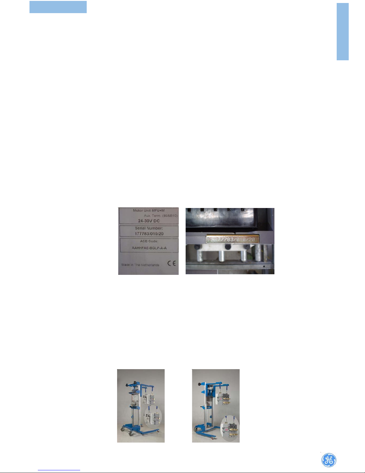
A dedicated serial number is allocated to each manufactured circuit breaker. This
number is located on both label mentioned below.
The serial number should be quoted in any communication concerning the circuit
breaker.
This number can be found in two places
(a) Top side on pull out transport hook .
(b) Left side of the front cover (View from front facia)
1 Allgemein1 Allgemein
1 Allgemein1 Allgemein
1 Allgemein
1.1 Einführ1.1 Einführ
1.1 Einführ1.1 Einführ
1.1 Einführ
ungung
ungung
ung
Dieses Handbuch beschreibt die normale Installations-,Betriebs- und
Wartungsprozeduren. Leistungsschalter Typ MPACT dürfen nur von
kompetentem, und geschultem Personal installiert ,betrieben und gewartet
werden.
Werden weitere Informationen zum Betrieb oder zur Wartung benötigt, wenden
Sie sich bitte an:GE Consumer & Industrial
1.21.2
1.21.2
1.2
QualitätssicherQualitätssicher
QualitätssicherQualitätssicher
Qualitätssicher
ungung
ungung
ung
Alle M-PACT Leistungsschalter sind nach den höchsten technischen Standards
entwickelt und gefertigt. Genaue Verfahren in Übereinstimmung mit der ISO 9001
garantieren höchste Produktqualität.
1.3 Bestück1.3 Bestück
1.3 Bestück1.3 Bestück
1.3 Bestück
ungslisteungsliste
ungslisteungsliste
ungsliste
Diese INformation ist auf zwei seperaten Leistungsschildern am Schalter vermerkt.
Ein Schild ist bei den Hilfsschaltern, und ein zweites an der linken Seite des Schalters
angebracht. Auf beiden Schildern sind der Schaltertyp, Nennstr om, Anzahl der Pole,
Auslöseeinheitstyp und Anzahl und Typ der internen Anbaugeräte vermerkt
1.41.4
1.41.4
1.4
SeriennummerSeriennummer
SeriennummerSeriennummer
Seriennummer
Jeder gefertigte Leistungsschalter erhält eine einmalig vergebene
Seriennummer, die an den beiden folgenden Stellen gut sichtbar angebracht ist:
(a) Auf der Oberseite einer der herausziehbaren Transportösen (siehe Fig.)
(b) Auf der linken Seite der Fronblende (von vorn gesehen)
1.5 Transpor1.5 Transpor
1.5 Transpor1.5 Transpor
1.5 Transpor
t Ut U
t Ut U
t U
. Ablage
. Ablage
. Ablage. Ablage
. Ablage
Die Verpackung schützt die Geräte gegen Umwelteinflüsse wie Staub und
Feuchtigkeit . Daher sollte die Verpackung erst dann entfernt werden, wenn der
Schalter installiert wird. Die Verpackung muss vollständig und mit Vorsicht
entfernt werden. Nachdem der Schalter ausgepackt ist kann er mit den seitlichen
Tragegriffen bewegt werden.
Wegen des großen Gewichts dieser Geräte sollten Hebehilfen wie Kran oder
Hubwagen benutzt werden.
Die Schalter sollten mit entspanntem Mechanismus und im ausgeschaltetem
Zustand gelagert werden.
1.5 Transpor1.5 Transpor
1.5 Transpor1.5 Transpor
1.5 Transpor
tation & Station & S
tation & Station & S
tation & S
toragetorage
toragetorage
torage
The packaging must protect the equipment against environmental influences, for
instance dust and moisture. Therefore, it is to be removed only when the mounting
works are started. Make sure, that the packaging material is removed carefully
and completely. After the packaging material has been removed, the circuit
breakers can be moved by handled feature of molded base attached on both
sides.
Due to the high weight of these units, auxiliary means of transportation, like built
in transportation hook on top of breaker can be utilized. Appropriate Lifting truck
is recommended for transportation of breaker.
Ensure that closing springs are discharged and circuit breakers are in the OFF
position while in storage.
GENERAL
Page 4

2
BREAKER
1.6 Safety Pr1.6 Safety Pr
1.6 Safety Pr1.6 Safety Pr
1.6 Safety Pr
ecautionsecautions
ecautionsecautions
ecautions
It is recommended that the following precautions be included in any procedural
instructions to personnel concerned with the handling, operation or maintenance
of ‘M-PACT PLUS’ circuit breakers.
During operation this circuit breaker is connected to dangerous voltages. When
the circuit breaker is switching high currents, especially short-circuit currents, hot
and ionized gas may be emitted.
Only qualified personnel are allowed to install, commission, maintain or modify
this device in accordance with relevant safety requirements. The circuit breake r
must be equipped with a proper fixed cover or installed in a suitable enclosure or
panel board to allow adequate safety clearance.
Before detailed inspection or any maintenance work is commenced:
• All electrical supplies to the circuit breaker should be switched off.
• The circuit breaker should be tripped to the OFF position and the closing springs
discharged. This releases stored energ y in the spring mechanism, thus eliminating
risk of injury due to unintentional tripping or closing during inspection and
maintenance.
While handling the breaker, care should be taken to avoid risk of injury f rom moving
parts.
• The circuit breaker and its accessories must always be used within their
designated ratings.
• Use of the breaker handling truck is recommended when removing the breaker
from its cassette.
Non compliance with this warning could result in equipment damage, severe
personnel injury or even life lost.
1.61.6
1.61.6
1.6
SicherheitsmassnahmenSicherheitsmassnahmen
SicherheitsmassnahmenSicherheitsmassnahmen
Sicherheitsmassnahmen
Es wird empfohlen, dass die folgenden Maßnahmen in jede handlungsmäßige
Instruktionen für das mit Handhabung, Betrieb und Wartung beauftragtem
Personal einbezogen w erden.
Im Einsatz ist dieser Leistungsschalter an gefährliche Spannungen angeschlossen.
Wenn der Schalter hohe S tröme, insbesondere Kurzschlussströme abschaltet,
treten heiße Gase auf der oberseite des Schalter aus.
Im Einsatz ist dieser Leistungsschalter an gefährliche Spannungen angeschlossen.
Wenn der Schalter hohe S tröme, insbesondere Kurzschlussströme abschaltet,
treten heiße Gase auf der oberseite des Schalter aus.
Vor Beginn einer detaillierten Inspektion oder Wartung ist zu gewährleisten:
• Spannungsfreiheit des Leistungsschalters
• Der Leistungsschalter ist auszuschalten und der
• Federkraftspeicher muss entspannt sein, um das Risiko von Verletzungen durch
versehentliches Auslösen oder Schließen W ährend der Arbeiten am Schalter
auszuschließen. Während der Arbeiten am Schalter ist sorgfältig auf das
Verletzungsrisiko dur ch bewegliche Teile zu achten.
• Die Verwendung einer optional erhältlichen Kabel-/ SammelschienenErdungsvorrichtung ist empfehlenswe rt für zusätzliche Sicherheit während der
Wartungsarbeiten. Leistungsschalter und Zubehör dür fen nur innerhalb ihr er
vor gesehenen Anwendungsgebiete eingesetzt werden.
• Die Benutzung des speziell für den M-PACT angebotenen Hubwagens ist
empfehlenswert , um den Leistungsschalter aus der Kassette zu heben.
GENERAL
Page 5

3
BREAKER
1)Handspannhebel
2)EIN Drucktaster
3)AUS Dr ucktaste
4)Schaltstellungsanzeige
5)Federkraftspeicherstellungsanzeige
6)Anschlussklemmen Hilfsschalter
7)Speichermodul PAMM
8)Elektronischer Auslöser
9)Anschlussklemmen Auslöser
1)Manual Charging handle.
2)Closing push button (ON).
3)Opening pushbutton (OFF).
4)Main contact position indicator.
5)Charging spring status indication.
6)Auxiliary Contacts.
7)PAMM.
8)Electronic trip unit.
9)Electronic release access lock.
Legend:Legend:
Legend:Legend:
Legend:
2. Pictur2. Pictur
2. Pictur2. Pictur
2. Pictur
ee
ee
e
PICTURE
6
3
1
5
4
2
9
8
7
Page 6

4
BREAKER
3 Specif3 Specif
3 Specif3 Specif
3 Specif
y on the ory on the or
y on the ory on the or
y on the or
derder
derder
der
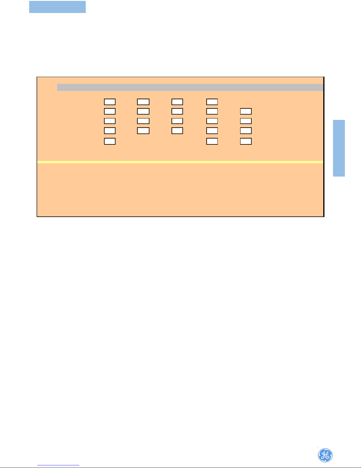
ORDER BREAKER
1 Device
T ype S (
50 k A
)Type N (
65kA
)Type H (
80 kA
)
2 Number of poles 3-Pole 4-Pole Neutral Left 4-Pole Neutral Ri ght
3 Sy stem 3 phase 3 wire 3 Phase 4 wire 4 Phase 4 wire
4 Typ e Top Connection Bottom Connection
Fixed Front Front
Withdrawable Rear Rear
Moving Portion Only Horizontal Horizontal
Cas sette Onl y Verti cal Vertical
5 Protection Autom atic Non-Automatic
M -PR O 17 P lus M-PR O 30
M -PR O 18 P lus M-PR O 40
6 M-PRO Language English French German (Available in M-Pro 18+)
7 Ear th Faul t o ptions
Un restricted (UEF) Restricted (REF) Stand-by (SEF)
8 Neutral protection Not req urie d 50% R ated 100% R at e d
9 M-PRO options Amm eter Operations counter
10 Type of trip unit
M-Pro 17 +
M-Pro 18 +
M-Pro 30L (wiht configurable input 24/48V DC)
M -Pr o 3 0H (wiht c onf igurable in pu t 11 0/130 V D C or 110 /250V AC)
M-Pro 40L (wiht configurable input 24/48V DC)
M -Pr o 4 0H (wiht c onf igurable in pu t 11 0/130 V D C or 110 /250V AC)
11 Drive Mechanism Manua lly
Motor o p era ted (MOP)
Two way voltage free contact
12
Rel eases
Cl osi ng Coil(CC) Shunt Trip(ST) Under v oltage(U V) Under voltage Time delayed(UV TD)
13
Auxiliaries
Carriage sw itch - Factory fi tted Carriage switch - L oose ki t
14.1
Interlocks
Castell k e y i n terloc k D oor In terlock (left hand)
Ronis K e y i n terloc k D oor interlo ck (right hand)
Profalux Key Interlock Circuit breaker Mis-Insertion Interlock
Ronis Cassette key i nterlock
Profalux Cassette Key Interlock
14.2
Cable Interlock 2 Way
1 from 3 wa y 2 fr om 3 wa y
(Type A only ) Type B D Type C
Cable length requried ( in centime ters )
100
160 200 250 3 00 3 50 40 0
Other (please specify below )
15
Miscellaneous
Mechanical Operations Counter ACB Lifting truck
IP54 door panel - Fixed/withdrawable type Titan Truck adaptor kit
16
Operations Manual
English French German
17
Documents
Certifica te of Co nform ity Test Certification
SPECIFY ON THE ORDER
Page 7
5
BREAKER
ORDER BREAKER
18 Control V oltage
ST MOP CC UV UV TD
24/30V DC
48V DC
110/130V AC/DC
(1)
220/250V AC/DC
(2)
380/440V AC/DC
(2)
(1)
DC
NA for UVTD
(2)DC
NA for UV /UV TD
19 Special requirements (PLEASE SPECIFY ANY I MPORTANT INSTRUCTIONS)
--------------- ----------------- ----------------- ----------------- ----------------- ---------------- ---------------------------------- ---------------
--------------- ----------------- ----------------- ----------------- ----------------- ---------------- ---------------------------------- ---------------
--------------- ----------------- ----------------- ----------------- ----------------- ---------------- ---------------------------------- ---------------
--------------- ----------------- ----------------- ----------------- ----------------- ---------------- ---------------------------------- ---------------
Frame 1&2
Page 8

6
BREAKER
4 Installation v4 Installation v
4 Installation v4 Installation v
4 Installation v
on M-Pon M-P
on M-Pon M-P
on M-P
AA
AA
A
CT PLCT PL
CT PLCT PL
CT PL
US LeistungsschalternUS Leistungsschaltern
US LeistungsschalternUS Leistungsschaltern
US Leistungsschaltern
Baugr Baugr
Baugr Baugr
Baugr
ößöß
ößöß
öß
e 1 und 2e 1 und 2
e 1 und 2e 1 und 2
e 1 und 2
4.1 Einbauor4.1 Einbauor
4.1 Einbauor4.1 Einbauor
4.1 Einbauor
tt
tt
t
Der Leistungsschalter soll in eine trockene, staubfreie, nicht korr osive
Atmosphäre eingebaut werden die des weiteren bezüglich Temperatur, Höhe
und Luftfeuchtigkeit den Richtlinien des IEC Standards IEC 947-1 entspricht.
Für spezielle Anwendungen die außerhalb der Standarddefinitionen liegen bitte
mit uns Rücksprache halten.
4.2 Festeinbau Schalter4.2 Festeinbau Schalter
4.2 Festeinbau Schalter4.2 Festeinbau Schalter
4.2 Festeinbau Schalter
Vor dem Anschluss des Schalters unbedingt Spannungsfreiheit sicherstellen.
Auch für Hilfspannungskreise.
4.3 Ausfahr4.3 Ausfahr
4.3 Ausfahr4.3 Ausfahr
4.3 Ausfahr
techniktechnik
techniktechnik
technik
Normaler Weise werden die Schalter für die Ausfahrtechnik zusammen mit der
Ausfahrtechnik geliefert .Zum Einbau des Einschubträgers muß zunächst der
Schalter entfernt werden (Siehe hier zu Abschnitt: “Ausfahren des
Leistungsschalters”).
Jetzt werden zunächst die Anschlüsse an die Sammelschienen oder Kabel
vorgenommen, dabei ist darauf zu achten das keine dauerhaften Zug-, Druckund Seiten- Kräfte auf den Einschubträger wirken.
Nach dem Anschluss der Hauptstrombahnen wird der Einschubträger mit M8
Schrauben an den hinter en und vorderen Befestigungslöchern befestigt. Diese
werden dann mit 25Nm angezogen. Es ist darauf zu achten das der
Einschubträgen nach der Montage keine Verformungen aufweißt und die
rechteckige Form weiter gegeben ist .
Wenn die Montage abgeschlossen ist muss die freie Bewegung der
Berührungsschutzabdeck ungen überprüft werden.
Zur Erdung ist der Einschubträger auf der rechten Seite (von Vorne gesehen) mit
einem Er dungspunkt versehen.
5 Betrieb Leistungsschalter5 Betrieb Leistungsschalter
5 Betrieb Leistungsschalter5 Betrieb Leistungsschalter
5 Betrieb Leistungsschalter
5.1 Einschaltv5.1 Einschaltv
5.1 Einschaltv5.1 Einschaltv
5.1 Einschaltv
oror
oror
or
gang:gang:
gang:gang:
gang:
Federkraftspeicher mit dem Handspannhebel spannen (Ca 7-8 Hübe erforderlich
zum vollständigen Spannen).
Ist der Leistungsschalter mit einem Motorantrieb ausgestattet beginnt der
Spannvorgang sobald dieser angesteuert wird.Drücken des Ein-Knopfes oder
Err egen der Einschaltspule (wenn v orhanden) bewirkt die sofortige Einschaltung
des Schalter.
Der Schalter kann nicht eingeschaltet werden wenn:
• Wenn der AUS-Knopf gedrückt ist
• Wenn der Schalter in Ausfahr techinik sich zwischen den positionen Trenn-,
Test- and Betriebsstellung befindet.
• Wenn am Mpro der Rückstellknopf hervorragt (Knopf drücken um wieder
Einschaltbereit zu sein)
• Ein Unter spannungsauslöser installiert und spannungslos ist
• Der Schalter sich in der Test- oder Betriebsstellung befindet und die Handkurbel
in der Öffnung steck t.
• Eine Zylinderschlossverriegelung aktiviert ist oder eine andere Verriegelung
(Kabelverriegelung) am Schalter angebaut und aktivier t ist.
5.2 Ausschaltv5.2 Ausschaltv
5.2 Ausschaltv5.2 Ausschaltv
5.2 Ausschaltv
oror
oror
or
gang:gang:
gang:gang:
gang:
Die Betätigung des Aus-Knopfes oder das Ansprechen des Arbeitsstromauslösers
(Falls vorhanden) bewirkt das Ausschalten.
Die Auslösung unter Fehlerbedingungen geschieht automatisch in Abhängigkeit
der gew ählten Parameter für die Auslöseeinheit.
4 Installing M-P4 Installing M-P
4 Installing M-P4 Installing M-P
4 Installing M-P
AA
AA
A
CT PLCT PL
CT PLCT PL
CT PL
US Frame 1 & 2US Frame 1 & 2
US Frame 1 & 2US Frame 1 & 2
US Frame 1 & 2
CirCir
CirCir
Cir
cuit Brcuit Br
cuit Brcuit Br
cuit Br
eakeak
eakeak
eak
erer
erer
er
ss
ss
s
4.1 Fitting4.1 Fitting
4.1 Fitting4.1 Fitting
4.1 Fitting
Install the switch in a dry, dust-free, non-corrosive, room, with temperature,
height and humidity in compliance with standard IEC 947-1.
For installations in special rooms or rooms which exceed the limits laid down by
the standard contact GE Consumer & Industrial.
4.24.2
4.24.2
4.2
Fixed typeFixed type
Fixed typeFixed type
Fixed type
Before connecting the main and auxiliary conductors of the circuit breaker and
its accessories, as auxiliary switches and releases, care is to be taken that all
conductors, connectors and terminals are not ener gized.
4.3 Draw4.3 Draw
4.3 Draw4.3 Draw
4.3 Draw
out typeout type
out typeout type
out type
Normally, drawout type cir cuit breakers will be delivered already mounted in
cassettes.Remove the breaker from its cassette using procedures described in
the section ‘Withdrawal of M-PACT Plus Circuit Break er’.Position the cassette
as required in the switchboard.
Note: The cassette may be lifted by hand but, if a handling truck or other lifting
gear is employed, all four of the lifting holes provided at front and rear of the
cassette should be used.
Position cassette in place and connect incomming and outgoing cables/busbars.
When connecting busbars ensure there is minimal deflection/stress to the back
of the cassette. Fix the cassette using 4 off M8 bolts to 25Nm at front and rear
fixing points. Note, the cassette base before and after fixing must be flat and
the frame square .
Check that the safety shutters move freely after the fixing bolts have been fully
tightened.
An earthing point is provided on the right hand side of each cassette (viewed
from front).
5 Operation5 Operation
5 Operation5 Operation
5 Operation
5.1 Closing pr5.1 Closing pr
5.1 Closing pr5.1 Closing pr
5.1 Closing pr
ocedurocedur
ocedurocedur
ocedur
ee
ee
e
Pull the charging handle out and down to charge the closing springs (requires
approximately 7-8 movements of the handle to fully charge).
If a motorised spring charging unit is fitted, the springs will be automatically
charged as soon as the motor is energized. Pressing the ON pushbutton or
energising the closing coil (if fitted) will close the circuit breaker.
Closing cannot occur if:
• The OFF button is in a depressed position.
• The breaker is positioned anywhere between CONNECTED, TEST and
DISCONNECTED positions.
• The electronic protection unit is at ‘Manual Reset’ and the reset button is
protruding from the front fascia. (Press the reset button to clear the breake r
for closing).
• An undervoltage trip is fitted but not energized.
• The breaker is in the TEST or CONNECTED position with the rack ing handle
inserted.
• A key interlock(e. g. Castell etc.) or direct interbreaker mechanical interlock
is operating on the break er.
5.2 Opening pr5.2 Opening pr
5.2 Opening pr5.2 Opening pr
5.2 Opening pr
ocedurocedur
ocedurocedur
ocedur
ee
ee
e
Pressing the OFF pushbutton or energisation of the shunt trip coil (if fitted) will
open the breaker.
Tripping under fault conditions will be automatic depending in settings used for
the protective devices.
Normally, drawout type cir cuit breakers will be delivered already mounted in
cassettes.
INSTALLATIONOPERATION
Page 9

7
BREAKER
6 Fitting Instr6 Fitting Instr
6 Fitting Instr6 Fitting Instr
6 Fitting Instr
uction - Accessoriesuction - Accessories
uction - Accessoriesuction - Accessories
uction - Accessories
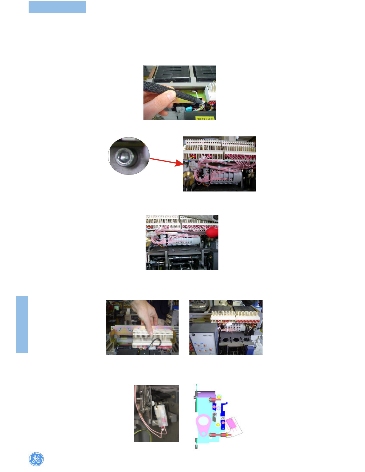
6.1 L .T. Auxiliary Blocks Replacement
A set of 32 self-aligning secondary cir cuit isolating contacts is provided in two
blocks, B and C, each clearly numbered 1 to 16. These are easily accessible at
the top of the circuit breaker and ensure isolation of secondary circuits when
M-PACTPLUS is in the DISCONNECTED position. Wiring terminals have a dual
connecting facility to allow termination of secondary wiring by scr ew or spade
connectors.
6.1.1 Connectors for auxiliary circuits
The LT auxiliary terminal blocks - B1 to B16 & C1 to C16 are situated at the top,
right hand side of a
M-PACTPLUS air circuit breaker. Withdrawable units have a
“moving” auxiliary contact block fitted to the moving portion of the
ACB and
fixed portion fitted to the cassette (cradle/housing). Fixed pattern breakers, have
both moving and fixed L.T blocks fitted to a mounting bracket and can be
replaced as a complete assembly. The following, demonstrates how to gain
access, remove and replace the auxiliar y terminal contact blocks.
6.1.2 Tool kit required
• Flat Bl aded screwdriver 8 mm (Used for removal of front panel fixing
screws and operation of racking shutter drive).
• Allen key set various (Used for removal horizontal part of spring
charging handle to allow complete removal of M-PACT Plus front
fascia and LT mounting bracket fixing scr ews).
6 Einbau Anleitung - Anbaugeräte6 Einbau Anleitung - Anbaugeräte
6 Einbau Anleitung - Anbaugeräte6 Einbau Anleitung - Anbaugeräte
6 Einbau Anleitung - Anbaugeräte
6.1 Steuerleitungskontakte
Ein Satz von 32 selbstausrichtenden Steuerleitungskontak ten ist in zwei Blöcke
B und C mit nummerierten Anschlüssen (1 bis 16) aufgeteilt. (Hinweis für
bestimmte weitere Schutzfunktionen ist ein dritter Block A eingebaut). Diese
leicht zugänglichen Kontakte oberhalb des Schalters trennen die Steuerleitungen
selbsttätig wenn der Schalter in Trennstellung verfahren wird. Die Steuerleitungen
können entweder mit Schraub oder Steck technik angeschlossen werden.
6.1.1Die S teuerleitungsklemmleisten B1-B16 und C1-C16 befinden sich oben
links am Schalter. IAusfahrtechnik hat einen beweglichen Block (am Schalter)
und einen festen Klemmblock (am Einschubträger). Festeinbauschalter haben
beides einen fest Block und einen beweglichen Klemmblock der mit eine Halter
in Position gehalten wird. Wie man sich Zugang zu den Klemmen verschafft um
sie ggf. zu ersetzen wird im folgenden gezeigt:
6.1.2 Werkzeug:
• 8 mm Schraubendreher (Für Deckelschrauben)
• Imbus Schlüsselsatz.
Einbau AnleitungEinbau Anleitung
Einbau AnleitungEinbau Anleitung
Einbau Anleitung
6.1.3 Spannungsfreiheit sicherstellen, Schalter in ‘Trennstellung’ verfahren bzw.
für Festeinbau alle elektrischen und mechanischen Verbindungen lösen, Schalter
entnehmen und auf eine geeignete Werkbank stellen.
Fitting InstrFitting Instr
Fitting InstrFitting Instr
Fitting Instr
uctionsuctions
uctionsuctions
uctions
6.1.3 The breaker should be safely isolated, fully withdrawn to DISCONNECTED
position, removed from the switchboard and placed on a suitable working
surface.
FITTING
INSTRUCTION
6.1.4
a) Schalter wieder Aufstellen, und nun den horizontalen Teil des Handspannhebels
abmontieren durch lösen der Imbus Schraube (Größe 5) die sich Seitlich im Griff
befindet.
b) Nun die 4 Deckelbefestigungsschrauben lösen und den Deckels bei
gleichzeitigen teilweisen Bestätigen des Hansspannhebels abnehmen. (Fig. b1
& b2)
6.1.4
a) Remove horizontal part of charging handle using 5 mm hexagonal key.
b) Unscrew 4 off front fascia fixing screws and remove front fascia by partially
pulling the charging handle downwards. (Fig. b1 & b2)
6.1.5 Access to a fixing screw situated behind the ‘electronic release’ protection relay is requir ed. To remove an ‘electronic release’ protection relay (if fitted), 3 x fixing nuts should be backed off (not removed) and the relay will slide
off the mounting plate.It may be necessary to remove a cable tie which supports the secondary wiring harness.
6.1.5 Es ist notwendig eine Schraube zu erreichen die sich hinter der
Auslöseeinheit befindet. Daher zunächst den Auslöser entfernen. Hier zu die dre i
Haltemuttern leicht lösen die Einheit ca 10mm nach oben schieben und dann
herausnehmen. Es ist unter Umständen notwendig einen Kabelbinder der den
Kabelbaum hält zu entfernen.
(b1)(b1)
(b1)(b1)
(b1)
(b2)(b2)
(b2)(b2)
(b2)
(a)(a)
(a)(a)
(a)
Page 10
8
BREAKER
6.1.8 The fixing screws do not have to be removed but loosened back, they may
be difficult to reach but ar e situated on the right hand aside and on the left hand
side. Access the right hand fixing screw may be difficult due to the auxiliary
switch wiring harness.
6.1.9 Once the mounting bracket is loose this will enable the removal of the LT
blocks from their respective locations. The aux. wiring can carefully be disconnected from the damaged block and exchanged. Care must be taken to ensure
correct reconnection to the auxiliary terminals.
Replace all items removed and return back into service.
6.1.8 Die Halteschrauben müssen nun gelöst werden, nicht komplett entfernen.
6.1.9Sobald der Haltebügel gelöst ist kann die Baugr uppe entfernt werden.
Die Verdrahtung des defekten Klemmblocks kann nun an einen
Austauschblock übertragenwerden.
Der Ruckbau erfolgt in umgekehrter Reihenfolge wie beschrieben.
6.2 Einbau mechanischer S6.2 Einbau mechanischer S
6.2 Einbau mechanischer S6.2 Einbau mechanischer S
6.2 Einbau mechanischer S
tt
tt
t
örmeldeschalterörmeldeschalter
örmeldeschalterörmeldeschalter
örmeldeschalter
6.2.1 Der Meldeschalter wird an den rechten unteren Befestigungsbolzen des
Auslösers montiert. Es ist darauf zu achten das der Betätigungshebel des
Mikroschalters nicht hinter dem vorstehenden Bolzen liegt.
6.2 Fitting instr6.2 Fitting instr
6.2 Fitting instr6.2 Fitting instr
6.2 Fitting instr
uctions for Mechanical alarm contactuctions for Mechanical alarm contact
uctions for Mechanical alarm contactuctions for Mechanical alarm contact
uctions for Mechanical alarm contact
6.2.1 Fit contact onto bottom right-hand foot of electronic releases unit using
existing nut & washer, with microswitch lever resting on top of the trip-pin.
6.1.6 This should be replaced once the L.T blocks have been replaced. For easier
access, all ancillary devices (shunt trip, etc.) should be temporarily removed.
6.1.7 The two fixing screws, which r etain the horizontal support bracket for the
LT connector s blocks, should now be accessible.
6.1.6 Der Auslöser sowie ggf. der Kabelbinder müssen wieder eingebaut werden
nachdem der Steuerklemmblock ausgetauscht wurde. Anbaugeräte wie
Arbeitsstromauslöser und Einschaltspule müssen vorrübergehend ausgebaut
werden.
6.1.7 Nun sind die beiden Halteschrauben für den horizontalen Haltebügel der
Klemmblöcke erreichbar.
FITTING
INSTRUCTION
Page 11

9
BREAKER
FITTING
INSTRUCTION
6.2.2 Loop wiring between electronic releases unit & alarm assy. Bracket
connect wires to LT-B7 & B8.
6.2.3 Fit pad & tie-wrap in position shown to keep wiring away from trip-paddle.
6.2.2 Kabel mit Flachsteckkontakten mit den Anschlüssen B7 und B8 der
Klemmblocke verbinden. Das Kabel muss zwischen Auslösen und
Störmeldeschalter verlegt werden.
6.2.3 Das Kabel mit Kabelbindern so fixieren das es nicht mit dem Auslösehebel
kollidiert.
6.36.3
6.36.3
6.3
Fitting instrFitting instr
Fitting instrFitting instr
Fitting instr
uctions for carriage switchuctions for carriage switch
uctions for carriage switchuctions for carriage switch
uctions for carriage switch
Fitting instrFitting instr
Fitting instrFitting instr
Fitting instr
uctionsuctions
uctionsuctions
uctions
6.3.1Assembly kit .
6.3.2 Fit length of ‘flexiform’ grommet into aper ture in low er left hand side of
cassette.
6.3 Einbauanleitung für den P6.3 Einbauanleitung für den P
6.3 Einbauanleitung für den P6.3 Einbauanleitung für den P
6.3 Einbauanleitung für den P
ositions-Meldeschalterositions-Meldeschalter
ositions-Meldeschalterositions-Meldeschalter
ositions-Meldeschalter
Einbau AnleitungEinbau Anleitung
Einbau AnleitungEinbau Anleitung
Einbau Anleitung
6.3.1 Einbausatz
6.3.2 Länge des Kantenschutzes (‘flexform’) an die Öffnung in der linken unteren
Ecke der Kassette anpassen und einsetzen.
Page 12

10
BREAKER
6.3.3 Feed cables through grommet in cassette side. (Wire to terminal blocks
after setting C-Switch).
6.3.4 Position carriage switch over two tapped holes (see Fig. below) on left hand
side of racking gear housing with switch return springs to front of cassette.
`````
6.3.4 Positionsmeldeschalter auf dem Kassettenboden links vom Einfahrgetriebe
über den vorgesehenen Gewindelöchern so positionieren das die Rückholfeder
des Meldeschalters nach Vorn zweigt.
6.3.3 Nun Die Kabel des Positionsmeldeschalters durch diese Öffnung führen.
(Anschluss an die Klemmblöcke nachdem der Meldeschalter montiert ist)
6.3.6 To set the carriage switch position, insert racking handle and rotate
clockwise until the ‘pusher’ is in its fully racked in position. The indicator shows
‘CONNECTED’ at this point.
6.3.6 Zum Einstellen des Meldeschalters die Handkurbel einstecken und im
Uhrzeigersinn solange drehen bis das Einfahrgetriebe den Anschlag für die
Eingefahrenposition erreicht hat. Die Positionsanzeige zeigt „Connected”.
6.3.5 Fit two M4 x 6 mm fixing screws and washers through carriage switch
mounting slots into tapped holes and fasten loosely in position.
6.3.5 Nun den Meldeschalter lose mit zwei M4x6mm Schrauben und Scheiben
durch die Schlitze des Meldeschalters in den Gewindelöchern befestigen.
FITTING
INSTRUCTION
Page 13

11
BREAKER
6.3.8 Remove gauge and rotate racking handle anti-clockwise until the pusher
is in the fully racked out position. The indicator shows ‘DISCONNECTED’ at this
point.
6.3.10 Stick numbers.
6.3.11 Fit cables on side of cassette.
6.3.8 Einstelllehre entfernen und mit der Handkurbel entgegen dem Uhrzeigersinn
den Einfahrmechanismus in voll Ausgefahrenen Position bringen. Die
Positionsanzeige zeigt
“
Disconnected”.
6.3.9 Anschlussleiste am Haltebügel befestigen.
6.3.10 Kennzeichnungsschild auf den Haltebügel aufkleben.
6.3.11 Kabel auf der Kassettenseitenplatte verlegen.
6.3.9 Fit terminal block on metal square.
6.3.7 Place setting gauge into position shown and hold firmly against forward
face of pusher. Adjust position of carriage switch until the upright drive face on
the clear plastic moulding is just in contact with setting gauge. Fully tighten
fixing screws
6.3.7 Die Einstelllehre wie dargestellt positionieren und gegen das Einfahrgetriebe
drücken. Nun den Meldeschalter so verschieben das, der transparente Teil des
Meldeschalters gerade die Einstelllehre berührt fest.
FITTING
INSTRUCTION
Page 14

12
BREAKER
6.3.12 Cut a cable at a time. 6.3.12 Ein Kabel nach dem anderen auf Länge schneiden.
6.3.13 Fit terminal.
6.3.14 Fit the wires with corresponding numbers.
6.3.13 Krimpkontakt “aufkrimpen”
6.3.14 Kabel mit entsprechender Zuordung an die Leiste anschließen
6.3.15 Screw the terminal blocks to the side of the cassette. 6.3.15 Anschlussleiste anbauen
6.3.16 Position the wires
6.3.16 Kabel Positionieren
FITTING
INSTRUCTION
Page 15

13
BREAKER
6.3.17 Fit wires with cable ties and stickers.
6.3.17 Kabel mit selbstklebenden halten und Kabelbindern fixieren.
6.3.20 Move breaker
6.3.21 Set it in test position (yellow).
6.3.20 Schalter einfahren
6.3.21 Position Test (Gelb)
6.3.18 Fit the circuit breaker and set it in disconnected position (green)
6.3.19 Check the wires with a tester:
1-2 Open contact
1-3 Closed contact.
4-5 Open contact.
4-6 Closed contact.
6.3.18 Leistungsschalter einsetzen in Trennstellung (Grün)
6.3.19 Prüfen mit Durchgangsprüfer:
1-2 Kein Durchgang
1-3 Durchgang
4-5 Kein Durchgang
4-6 Durchgang
FITTING
INSTRUCTION
Page 16

14
BREAKER
6.3.23 Fit the circuit breaker and set it in connected position (red)
6.3.22 Check the wires with a tester:
7-8 Open contact
7-9 Closed contact.
10-11 Open contact.
10-12 Closed contact.
6.3.23 Schalter voll einfahren (Rot)
6.3.22 Prüfen mit Durchgangsprüfer:
7-8 Kein Durchgang
7-9 Durchgang
10-11 Kein Durchgang
10-12 Durchgang
6.3.24 Check the wires with a tester:
13-14 Open contact
13-15 Closed contact.
16-17 Open contact.
16-18 Closed contact.
The standard configaration of the carriage switch circuits to sense the breaker
position during racking is:
2 at DISCONNECTED (1 NO + 1 NC)
2 at TEST (1 NO + 1NC)
2 at CONNECTED (1 NO + 1NC)
The 6 circuits may be re-configured by customer to give up to:
3 at DISCONNECTED (1 NO + 1 NC)
6 at TEST (1 NO + 1 NC)
6 at CONNECTED (1 NO + 1 NC)
IN any combination up to the 6 circuit maximum.
6.3.24 Prüfen mit Durchgangsprüfer:
13-14 Kein Durchgang
13-15 Durchgang
16-17 Kein Durchgang
16-18 Durchgang
Die Werkskonfiguration des Meldeschalters ist wie folgt:
2 Kontakte Trennposition (1 Öffner, 1 Schließer)
2 Kontakte Testposition (1 Öffner, 1 Schließ er)
2 Kontakte Einfahrposition (1 Öffner, 1 Schließer)
Die 6 Kontakte können so modifiziert werden das sich maximal folgende
Zuordnung erreichen lässt:
3 Kontakte Trennposition (1 NO + 1 NC)
6 Kontakte Testposition (1 NO + 1 NC)
6 Kontakte Einfahrposition (1 NO + 1 NC)
FITTING
INSTRUCTION
Page 17

15
BREAKER
Trennung
Disconnected
Test
Test
Betrieb
Connected
If the carriage switch has been fitted and wired to the cassette the following
procedure should be followed.
1. Unhook the return springs, first from the carriage switch frame and then from
the clear plastic moulding.
2. Remove 2 off M4 x 6mm carriage switch fixing screws leaving the carriage
switch held in position by the wiring.
3. Lift the carriage switch slightly and slide out the moulding from the rear of the
assembly.
4. The trip pins on the moulding are snapped in from its underside and can be pushed
out using fingures or an appropriate screwdriver in the slot between the retaining
legs.
5. Reconfigure by snapping the pins back into the required locations ensuring that
the head on the trip pin is radially located in the adjacent slot.
6. Slide moulding fully back into carriage switch frame and reconnected the left
hand return springs.
7. Reset the position of the carriage switch by following steps 3 to 7.
8. Reconnected the right hand return spring.
Cables exiting cassette side
Position of switch in cassette
Position setting gauge in place
Ist der Meldeschalter bereits montiert und verdrahtet bitte wie folgt vorgehen:
1. Dei Rückholfedern des Meldeschalters zunächst vom Meldeschalter und dann
vom transparenten Plastikteil abnehmen.
2. Die Montageschrauben des Meldeschalters (M4 x 6mm) entfernen. Der
Schalter wird durch die Verdrahtung in Position gehalten.
3. Den Meldeschalter leicht anheben und das Plastikteil nach hinten
rausschieben.
4. Die Antriebsstößel der Mikroschalter können aus dem Plastikteil entweder mit
der Hand oder einem Schraubendrehen herausgedrückt werden.
5. Die geänderte Funktionsweise kann nun durch wiedereinstecken der
Antriebsstößel an gewünschter Position eingestellt werden.
6. Nun das Kunststoffteil wieder in den Träger einführen und die linke
Rückholfeder wieder einsetzen.
7. Einstellen des Meldeschalter wie oben beschrieben .
8. Nun die rechte Rückholfeder wieder einsetzen.
Kabelausgang Kassettenseite
Position des Meldeschalters in der Kassette
Position Einstelllehre
FITTING
INSTRUCTION
Page 18

16
BREAKER
The standard configuration is two switches for each position as illustrated above
(Fig.).
Note, the carriage switch will maintain a disconnected indication even when the
M-PACT Plus is fully withdrawn or removed.
Betätigung
Trip Pin
Die normal Konfiguration des Meldeschalters hat zwei Kontakte pro Position
(Siehe Abbildung).
Hinweis: Der Meldeschalter behält die Trennpositionssignalisierung bei auch
wenn der Leistungsschalter aus der Kassette entnommen wird.
6.3.25 Carriage switch- how to make the NO/NC Conversion in the contact using
the Pin.
FITTING
INSTRUCTION
6.3.25 Positionsmeldekontakt - wie die Schließer / Öffner Umkehrung unter
Verwendung der Stecker funktioniert.
PLASTIC PART WITH PIN HOLES
123
456
789
10 11 12
13 14 15
DISCONNECTED BANK
Trennung
TE S T BAN K
Tes t
CONNECTED BANK
Betrieb
Disconnect
Tre nnung
TEST
Test
Connect
Betrieb
1 2 3 4 5678 9101112131415
222xx xx xx
006 xxx x x x
024 xx xxxx
114x x xxxx
PIN SettingNo. of M icroswitches
Page 19

17
BREAKER
6.4 Fitting Instr6.4 Fitting Instr
6.4 Fitting Instr6.4 Fitting Instr
6.4 Fitting Instr
uctionuction
uctionuction
uction
- Electrical Accessories- Electrical Accessories
- Electrical Accessories- Electrical Accessories
- Electrical Accessories
Motorised spring charMotorised spring char
Motorised spring charMotorised spring char
Motorised spring char
ging unitging unit
ging unitging unit
ging unit
6.4.1 Ensure circuit breaker is open with springs discharged. For DC motors, fix
motor in position shown (if supplied, Fig.) using the two fixing screws to a torque of
5Nm. (Refer LLD11PC004)
6.4.2 Plug motor connection to motor harness of the breaker.
Remove earth strap fixing and attach the additional motor filter ground wire to
the base plate as shown (fig.) to a torque of 7Nm.
6.4.3 Orientate the motor unit as shown (Fig.), locating the gearbox bearing onto
the protruding motor drive shaft, pushing it home until flush with the mechanism
sideplate. If it does not move easily to the flush position, pull the charging handle
gently down to ease movement.
Fix in position using three M5 bolts through holes provided in the gearbox endplate
(tighten to 6.4Nm torque).
6.4.4 Manually charge the closing springs and carefully locate the plastic switch
actuator over the protruding drive shaft (Fig.), ensuring the switch operating arm is
correctly positioned (switch arm should be in the ‘cut out’ portion of the motor
switch actuator). Use a suitably sized washer and M4 bolt (into the shaft end) to fix
actuator (tighten to 5Nm torque).
Connect modular plug from filter to motor unit.
Connect the remaining earth wire from the filter to the earth point on the rear of
the motor body.
Note:
1. Limit switch information for the Motor Operator( b&c ).
2. Show the Removal of Motor operator as well as motor operator limit switch for
the both AC&DC combination.
6.46.4
6.46.4
6.4
Einbau Anleitung - elekEinbau Anleitung - elek
Einbau Anleitung - elekEinbau Anleitung - elek
Einbau Anleitung - elek
trische Anbauteiletrische Anbauteile
trische Anbauteiletrische Anbauteile
trische Anbauteile
MotorantriebMotorantrieb
MotorantriebMotorantrieb
Motorantrieb
6.4.1 Es ist sicherzustellen, dass der Schalter ausgeschaltet und der
Federkraftspeicher entspannt ist. Für DC – Motorantriebe ist der Motorfilter (wenn
vorhanden) wie in Fig. gezeigt mit zwei Schrauben und einem Anzugsdrehmoment
von 5 Nm zu montieren. (verweisen Sie LLD11PC004)
6.4.2
Verbinde die Anschlüsse des Motors mit dem Nylon Stecker des
Kabelbaums.
Erdungs-Flexband lösen und zusätzliches Motorfilter – Erdungskabel zur
Grundplatte wie in Fig. gezeigt hinzufügen und festziehen (Anzugsdrehmoment
7Nm).
6.4.3 Motor/Getriebeeinheit gemäss Fig. so ausrichten, dass das Getriebelager auf
dem vorstehenden Motorwelle passt, dann hereindrücken, bis es an der Platine
des Antriebs anliegt. Lässt sich die Einheit nicht leicht einfügen, Handspannhebel
langsam nach unten bewegen, um Einsetzen zu erleichtern.
Motor/Getriebeeinheit mit drei M5 Schrauben durch die Befestigungslöcher im
Getriebegehäuse festschrauben (Drehmoment 6.4Nm).
6.4.4 Federkraftspeicher manuell spannen und den Plastikhebelfür
die Schalterbetätigung auf die hervorstehenden Antriebswelle(Fig.) stecken,
dabei beachten, dass sich der Schalterbetätigungshebel in der korrekten Position
befindet.(Hebel sollte sich im Ausschnitt des Schalterbetätigungshebels
befinden). Hebel mit einer M4 Schraube und einer geeigneten Unterlegscheibe
auf dem Schaft befestigen (Drehmoment 5Nm).
Elektrische Verbindung zwischen Filter und Motor/Getriebeeinheit herstellen.
Verbleibendes Erdungskabel vom Filter mit Erdungspunkt an der Rückseite des
Motorgehäuses verbinden.
Hinweis:
1.Grenzschalterinformation für den Motorantrieb fehlt ( b&c )
2.Zeigt Ausbau von Motor und Grenzschalter für Ac und DC Variante.
FITTING
INSTRUCTION
1.Motor driv1.Motor driv
1.Motor driv1.Motor driv
1.Motor driv
ee
ee
e
shaftshaft
shaftshaft
shaft
1.Motor1.Motor
1.Motor1.Motor
1.Motor
ww
ww
w
elleelle
elleelle
elle
(a)(a)
(a)(a)
(a)
(b)(b)
(b)(b)
(b)
(c)(c)
(c)(c)
(c)
(d)(d)
(d)(d)
(d)
Page 20

18
BREAKER
6.5.4 Tilt backwards until the rear hooks engage in the slots and press down into
position.
6.5.4 Nun die Spule nach hinten drehen bis die Schnapphaken greifen.
6.5 Closing coil6.5 Closing coil
6.5 Closing coil6.5 Closing coil
6.5 Closing coil
The closing coil is a clip on device and requires no fasteners. Mounting positions
of the three units (closing coil, shunt trip coil and undervoltage release) are not
interchangeable and this is ensured by the use of unique footprint for each type
of unit.
Fitting instrFitting instr
Fitting instrFitting instr
Fitting instr
uctionsuctions
uctionsuctions
uctions
6.5.1Closing coil.
6.5.2 The breaker should be safely isolated and fully withdrawn to disconnected
position. Remove the front fascia by loosening the 4 fixing screws. The horizontal
part of the charging handle must also be removed. The closing coil should be
mounted in the central position in key ways provided.
6.5.3 Holding closing coil in one hand tilt the unit forward, engage front hooks
into top support plate.
6.5 Einschaltspule6.5 Einschaltspule
6.5 Einschaltspule6.5 Einschaltspule
6.5 Einschaltspule
Die Einschaltspule wird ohne Befestigungsschrauben in die entsprechenden
Öffnungen im Mechanismus eingeschnappt. Die Einbaupositionen der
Einschaltspule, des Arbeitsstromauslösers und des Unterspannungsauslösers sind
nicht austauschbar. Jede Spule ist so gestaltet das sie nur in die für sie vorgesehene
Position passt.
Einbauanleitung:Einbauanleitung:
Einbauanleitung:Einbauanleitung:
Einbauanleitung:
6.5.1 Einschaltspule
6.5.2 Spannungsfreiheit muss gewährleistet sein und der Schalter muss in
Trennposition verfahren sein. Nun zunächst den horizontalen Teil des
Handspannhebels abnehmen und danach den Deckel.
6.5.3 Die Einschaltspule nach vorne geneigt in einer Hand haltend in die vorderen
Befestigungsschlitze einführen.
FITTING
INSTRUCTION
Page 21

19
BREAKER
AB C
6 5 4 3 2 1
_
+
CC
1615141312111098 7
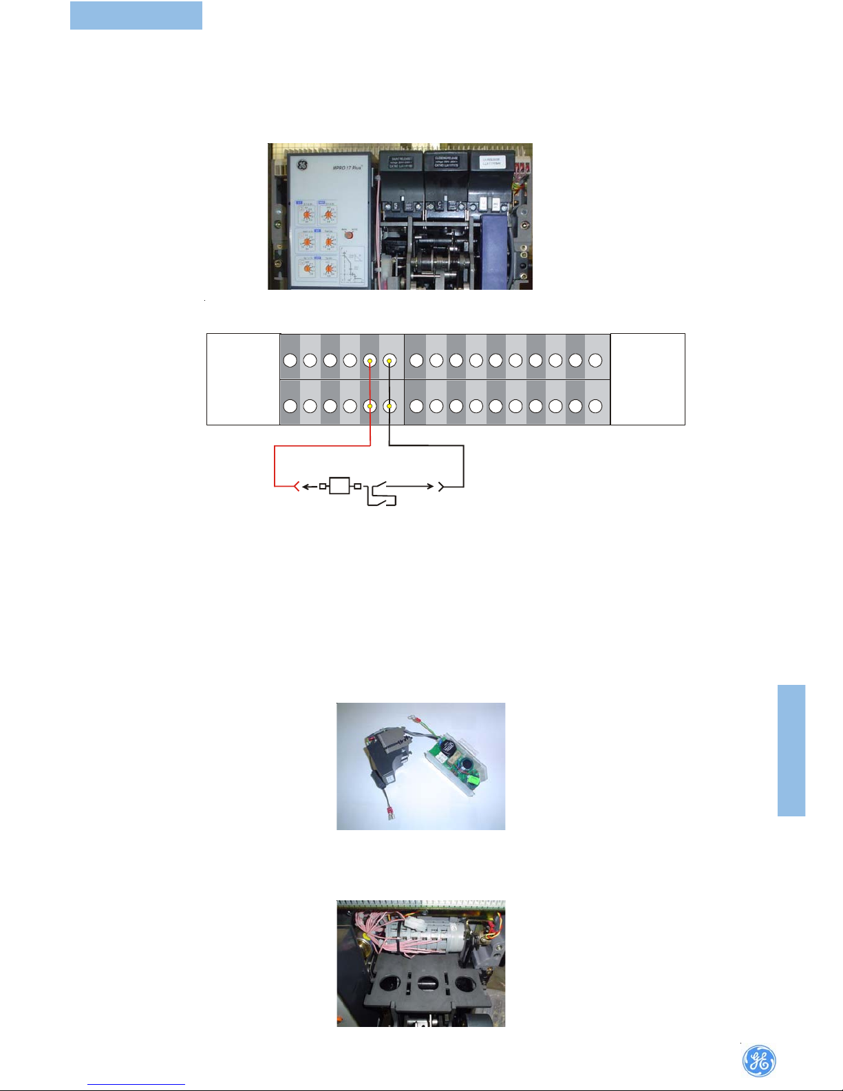
6.5.5 Connect closing coil flying leads into low tension auxiliary isolating contact terminals B13 and B14 as per schematic diagram, observing polarity markings on DC versions.
6.5.6 The front fascia must now be replaced in the reverse order to the removal.
The closing coil is now fitted and ready for testing.
6.5.5 Danach die Einschaltspule elektrisch an Klemmblock B13 und B 14
anschließen. Auf Polung für DC Variante achten.
6.5.6 Jetzt muss der Deckel und der Handspannhebel wieder angebaut werden.
Jetzt ist die Einschalspule bereit um eine Funktionsprüfung durchzuführen.
(View fr(View fr
(View fr(View fr
(View fr
om from fr
om from fr
om fr
ont side of bront side of br
ont side of bront side of br
ont side of br
eakeak
eakeak
eak
er after rer after r
er after rer after r
er after r
emovemov
emovemov
emov
al of facia coval of facia cov
al of facia coval of facia cov
al of facia cov
er)er)
er)er)
er)
FITTING
INSTRUCTION
Page 22

20
BREAKER
6.66.6
6.66.6
6.6
Shunt trip coilShunt trip coil
Shunt trip coilShunt trip coil
Shunt trip coil
The shunt trip coil is a clip on device and requires no fasteners. Mounting positions
of the three units (closing coil, shunt trip coil and undervoltage release) are not
interchangeable and this is ensured by the use of unique footprint for each type
of unit.
Fitting instrFitting instr
Fitting instrFitting instr
Fitting instr
uctionsuctions
uctionsuctions
uctions
6.6.1Shunt Trip coil.
6.6.2 The breaker should be safely isolated and fully withdrawn to disconnected
position.Remove the front facia by loosening the 4 fixing screws. The horizontal
part of the charging handle must also be removed.The shunt trip coil should be
mounted in the left hand position in key ways provided.
6.6.3 Holding shunt coil in one hand tilt the unit forward, engage front hooks into
top support plate.
6.6.4 Tilt backwards until the rear hooks engage in the slots and press down into
position.
6.66.6
6.66.6
6.6
ArbeitsstrArbeitsstr
ArbeitsstrArbeitsstr
Arbeitsstr
omauslöseromauslöser
omauslöseromauslöser
omauslöser
Der Arbeitsstromauslöser wird ohne Befestigungsschrauben in die
entsprechenden Öffnungen im Mechanismus eingeschnappt. Die
Einbaupositionen der Einschaltspule, des Arbeitsstromauslösers und des
Unterspannungsauslösers sind nicht austauschbar. Jede Spule ist so gestaltet
das sie nur in die für sie vorgesehene Position passt.
Einbauanleitung:Einbauanleitung:
Einbauanleitung:Einbauanleitung:
Einbauanleitung:
6.6.1 Arbeitsstromauslöser
6.6.2 Spannungsfreiheit muss gewährleistet sein und der Schalter muss in
Trennposition verfahren sein. Nun zunächst den horizontalen Teil des
Handspannhebels abnehmen und danach den Deckel.
6.6.3 Den Arbeitsstromauslöser nach vorne geneigt in einer Hand haltend in die
vorderen Befestigungsschlitze einführen.
6.6.4 Nun die Spule nach hinten drehen bis die Schnapphaken greifen.
6.6.5 Danach den Arbeitsstromauslöser elektrisch an Klemmblock B11 und B 12
anschließen. Auf Polung für DC Variante achten.
6.6.5 Connect shunt trip coil flying lead into nylon modular socket making connection to low tension auxiliary isolating contact terminals B11 and B12 as per
schematic diagram, observing polarity marking on DC versions.
FITTING
INSTRUCTION
Page 23
21
BREAKER
6.7 Under6.7 Under
6.7 Under6.7 Under
6.7 Under
vv
vv
v
oltage roltage r
oltage roltage r
oltage r
eleaseelease
eleaseelease
elease
The undervoltage release coil is a partial clip on device and requires fasteners for
mounting the external resistor unit. Mounting positions of the three units (closing
coil, shunt trip coil and undervoltage release) are not interchangeable and this is
ensured by the use of unique footprint for each type of unit.
Fitting instrFitting instr
Fitting instrFitting instr
Fitting instr
uctionsuctions
uctionsuctions
uctions
6.7.1Undervoltage release.
6.7.2 The breaker should be safely isolated and fully withdrawn to disconnected
position. Remove the front facia by loosening the 4 fixing screws. The horizontal
part of the charging handle must be removed. The undervoltage release coil should
be mounted in the right position in key ways provided.
6.6.6 Jetzt müssen der Deckel und der Handspannhebel wieder angebaut werden.
Jetzt ist der Arbeitsstromauslöser bereit um eine Funktionsprüfung
durchzuführen.
6.76.7
6.76.7
6.7
UnterUnter
UnterUnter
Unter
spannungsauslöserspannungsauslöser
spannungsauslöserspannungsauslöser
spannungsauslöser
Die Unterspannungsauslöserspule wird ohne Befestigungsschrauben in die
entsprechenden Öffnungen im Mechanismus eingeschnappt. Die
Einbaupositionen der Einschaltspule, des Arbeitsstromauslösers und des
Unterspannungsauslösers sind nicht austauschbar. Jede Spule ist so gestaltet
das sie nur in die für sie vorgesehene Position passt. Befestigungsschrauben
werden nur für die separate Elektronik benötigt.
Einbauanleitung:Einbauanleitung:
Einbauanleitung:Einbauanleitung:
Einbauanleitung:
6.7.1 Unterspannungsauslöserspule und separate Elektronik.
6.7.2 Spannungsfreiheit muss gewährleistet sein und der Schalter muss in
Trennposition verfahren sein. Nun zunächst den horizontalen Teil des
Handspannhebels abnehmen und danach den Deckel.
6.6.6 The front facia must now be replaced in the reverse order to the removal.The
shunt trip coil is now is fitted and ready for testing
(View fr(View fr
(View fr(View fr
(View fr
om from fr
om from fr
om fr
ont side of bront side of br
ont side of bront side of br
ont side of br
eakeak
eakeak
eak
er after rer after r
er after rer after r
er after r
emovemov
emovemov
emov
al of facia coval of facia cov
al of facia coval of facia cov
al of facia cov
er)er)
er)er)
er)
FITTING
INSTRUCTION
AB C
6 5 4 3 2 1 1615
14
1312111098 7
+VE
ST
- VE
Page 24

22
BREAKER
6.7.3 Holding undervoltage release coil in one hand tilt the unit forward, engage
front hooks into top support plate.
6.7.4 Tilt backwards until the rear hooks engage in the slots and press down into
position.
6.7.5 Fix external resistor unit in place with the 2 off M5 screws and shake proof
washers provided.
6.7.6 Connect undervoltage release coil flying leads into low-tension auxiliary
isolating contact terminals B15 and B16 as per schematic diagram, observing
polarity markings on DC versions.
6.7.7 The front facia must now be placed in the reverse order to the removal.
6.7.3 Die Unterspannungsauslöserspule nach vorne geneigt in einer Hand haltend
in die vorderen Befestigungsschlitze einführen.
6.7.4 Nun die Spule nach hinten drehen bis die Schnapphaken greifen.
6.7.5 Die externe Elektronik mit zwei M5 Schrauben nebst Vibrationsschutz
Scheiben anbringen.
6.7.6 Danach den Unterspannungsauslöser elektrisch an Klemmblock B15 und
B 16 anschließen. Auf Polung für DC Variante achten.
6.7.7 Den Deckel und den Handspannhebel wieder anbauen.
FITTING
INSTRUCTION
6.7.8 The undervoltage release coil is now is fitted and ready for testing.
6.7.8 Jetzt ist der Arbeitsstromauslöser bereit um eine Funktionsprüfung
durchzuführen.
Page 25

23
BREAKER
6.8 Pushbutton padlock6.8 Pushbutton padlock
6.8 Pushbutton padlock6.8 Pushbutton padlock
6.8 Pushbutton padlock
inging
inging
ing
Denies unauthorised access to ON/OFF pushbuttons (Fig.).
Raise the appropriate window(s) and pass padlock hasp through the locking eye.
Use padlock with hasp 8mm diameter maximum (6mm minimum).
6.8.1 T6.8.1 T
6.8.1 T6.8.1 T
6.8.1 T
o latch OFF pushbutton in depro latch OFF pushbutton in depr
o latch OFF pushbutton in depro latch OFF pushbutton in depr
o latch OFF pushbutton in depr
essed positionessed position
essed positionessed position
essed position
• Depress the button fully and hold.
• Using a flat bladed screwdriver, turn the latch above the OFF button
anti-clockwise through 90
0.
Access to both pushbutton and latch can be denied
by application of a padlock as above.
6.8.2 Cir6.8.2 Cir
6.8.2 Cir6.8.2 Cir
6.8.2 Cir
cuit brcuit br
cuit brcuit br
cuit br
eakeak
eakeak
eak
er security padlocker security padlock
er security padlocker security padlock
er security padlock
inging
inging
ing
To lock in the DISCONNECTED position for security.
• With position indicator showing DISCONNECTED, remove racking handle from
the operating position
• Pull forward the locking bar until the locking eye is exposed and hold while
inserting padlock hasp.
• Up to three padlocks (required hasp diameter 6 mm) may be applied for extra
security.
6.8 V6.8 V
6.8 V6.8 V
6.8 V
erriegelung der Betätigungsknöpfeerriegelung der Betätigungsknöpfe
erriegelung der Betätigungsknöpfeerriegelung der Betätigungsknöpfe
erriegelung der Betätigungsknöpfe
Verhindert den unbefugten Zugriff zu den EIN - und AUS –Tastern (Fig.).
Die/den entsprechendende(n) Schieber hochschieben und das Bügelschloss in der
Öffnung einhängen.
Geeignet für Bügelschlösser mit 8 mm Bügeldurchmesser (6 mm minimal)
6.8.16.8.1
6.8.16.8.1
6.8.1
VV
VV
V
erriegelung der Austaste in gedrückerriegelung der Austaste in gedrück
erriegelung der Austaste in gedrückerriegelung der Austaste in gedrück
erriegelung der Austaste in gedrück
ter Ster S
ter Ster S
ter S
tellungtellung
tellungtellung
tellung
• Austaste drücken und gedrückt halten.
• Mit einem Schraubendreher der Verriegelungsknopf oberhalb der Taste um
90° nach links drehen. Verriegelung wie unter 16 beschrieben.
6.8.26.8.2
6.8.26.8.2
6.8.2
SicherheitsvSicherheitsv
SicherheitsvSicherheitsv
Sicherheitsv
erriegelung Leistungsschaltererriegelung Leistungsschalter
erriegelung Leistungsschaltererriegelung Leistungsschalter
erriegelung Leistungsschalter
Verriegelung in Trennstellung
• Zeigt die Schalterpositionsanzeige die Trennstellung an Handkurbel entfernen
• Verriegelungsgestänge soweit herausziehen bis Öffnung frei zugänglich,
Gestänge festhalten und Bügelschloss einhängen.
• Bis zu Drei Bügelschlösser (max 6mm Bügeldurchmesser) können eingehängt
werden.
(View fr(View fr
(View fr(View fr
(View fr
om from fr
om from fr
om fr
ont side of bront side of br
ont side of bront side of br
ont side of br
eakeak
eakeak
eak
er after rer after r
er after rer after r
er after r
emovemov
emovemov
emov
al of facia coval of facia cov
al of facia coval of facia cov
al of facia cov
er)er)
er)er)
er)
1.Locking bar
1
FITTING
INSTRUCTION
AB C
5 4 3
2
1
_
+
UV
6 7 8 9 10 11 13 14 15 16 12
Page 26
24
BREAKER
FITTING
INSTRUCTION
A
B
6.9 SPECIAL FEATURE
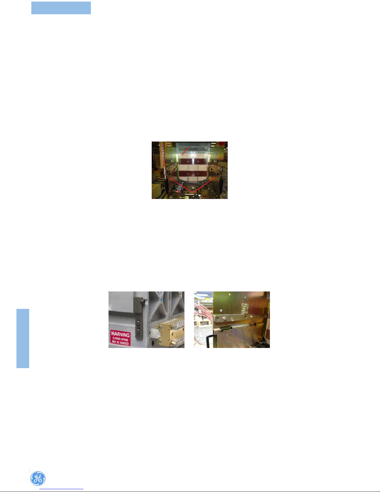
6.9.1 Prop open feature (For use by trained personnel)
To inspect the main fixed contacts each shutter (or both) may be propped
open.
Warning: Unless previously isolated fixed contacts on the incoming side will
be “live’.
•
Remove the circuit breaker from its cassette.
• Push the racking rail in until the mechanism opens the required shutter.
Viewing the cassette from the front, the racking rail on the left opens the
bottom shutter. The right hand rail opens the top shutter.
• Pull the racking rails out to reclose the shutters
A) Top shutter
B) Racking rails
6.9 SPEZIELLES ZUBEHÖR
6.9.1 Berührungsschutzabdeckung – Inspektion der Einfahrkontakte –
Nur für geschultes Personal
Zur Inspektion der feststehenden Hauptkontakte in der Kassette kann jede
Abdeckung (oder beide Hochgeschoben werden.
Warnung: Wenn die Anlage nicht freigeschaltet ist führen die
einspeiseseitigen Kontakte Spannung!
• Den Leistungsschalter herausnehmen
• Nun die Führungsschienen soweit hineindrücken bis die gewünschte
Abdeckung öffnet. Von Vorne gesehen öffnet die linke Führungsschiene die
untere Abdeckung und die rechte die obere Abdeckung.
• Führungsschienen wieder herausziehen um die Abdeckungen zu
schliessen.
A) Obere Abdeckung
B) Führungsschienen
6.9.2 Breaker mis-insertion stop
This ‘pin and gate’ device prevents insertion of a circuit breaker into a cassette
if the nominal rating of the breaker is incompatible with that of the cassette
and its ancillary equipment.
The figure shows a pin block assembly mounted on the circuit breaker. The
figure shows the corresponding restrainer assembly mounted on the cassette.
If necessary, the number of ‘ pin and gate’ combinations can be increased
by fitting mis-insertion stops to both sides of given breaker and cassette.
6.9.2 Verwechslungsschutz
Dieser aus “Stift und Sperre” bestehende Kodiersatz verhindert das Einsetzen
eines Leistungsschalters falsche Nennstromtragfähigkeit in die Kassette.
Das Bild zeigt den am Schalter montierten Kodierstiftblock. Das Bild zeigt
das passende Gegenstück in der Kasette.
Wenn nötig können zusätzliche Verriegelungen erreicht werden indem ein
zweiter Kodiersatz auf der anderen Kassettenseite angebaut wird.
Page 27

25
BREAKER
6.9.3 Safety shutters Security padlocking 6.9.3 Berührungsschutzabdeckung - Sicherheitsverriegelung
F
Brass spacing ring, block
lever, fixing nut
Messing Distanzring,
Blockierhebel,
Befestigungsmutter
E
Positioners
Positionierungsscheiben
A
Fixing Plate
Befestigungsplatte
B
Elastic Rings
Elastische Scheiben
C
Fixing Nuts
Befestigungsmuttern
D
Key Lock Bar
Zylinderschloss
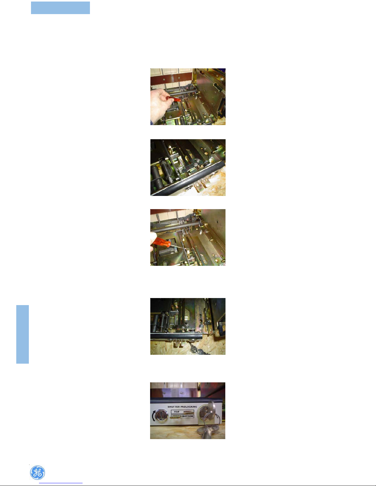
6.9.3.2 Remove the front cover by, unscrewing the fixing screws.
6.9.3.3 Unscrew the nut(C) on the top of the black tube and remove it from the
stud.
6.9.3.2 Frontabdeckung abbauen (Befestigungsschrauben lösen)
6.9.3.3 Mutter oben auf(C) dem Handkurbelhalterrohr entfernen und das Rohr
entfernen.
6.9.3.4 Remove the elastic rings(B) and the rods. Pre-existing nuts. 6.9.3.4 Hebel und elastische Ringe(B) entfernen durch lösen der abgebildeten
Muttern.
6.9.3.1 Fasteners
FITTING
INSTRUCTION
Page 28
26
BREAKER
6.9.3.6 Locate the lever in front of the pin.
6.9.3.7 Screw the fixing nuts (C) of the plate.
6.9.3.8 Insert the barrel of key-lock (D) into the suitable hole on the front cover
6.9.3.9 Screw the barrel of key lock.
6.9.3.6 Die Hebel vor den abgebildeten Bolzen montieren.
6.9.3.7 Mit gelieferten Muttern (C) anschrauben.
6.9.3.8 Zylinderschloss (D) in passendes Loch in der Frontabdeckung
einsetzen
6.9.3.9 Zylinderschloss festziehen
6.9.3.5 Locate support plate (A) over the pre-existing nuts and fix the provided
rods with elastic rings (B). Fixing point of the rods with elastic rings.
6.9.3.5 Nun Befestigungsplatte (A) auf die Bolzen (siehe 9) anbauen und die
mitgelieferten Verriegelungshebel mit den Elastischen Scheiben (B)
montieren
FITTING
INSTRUCTION
Page 29
27
BREAKER
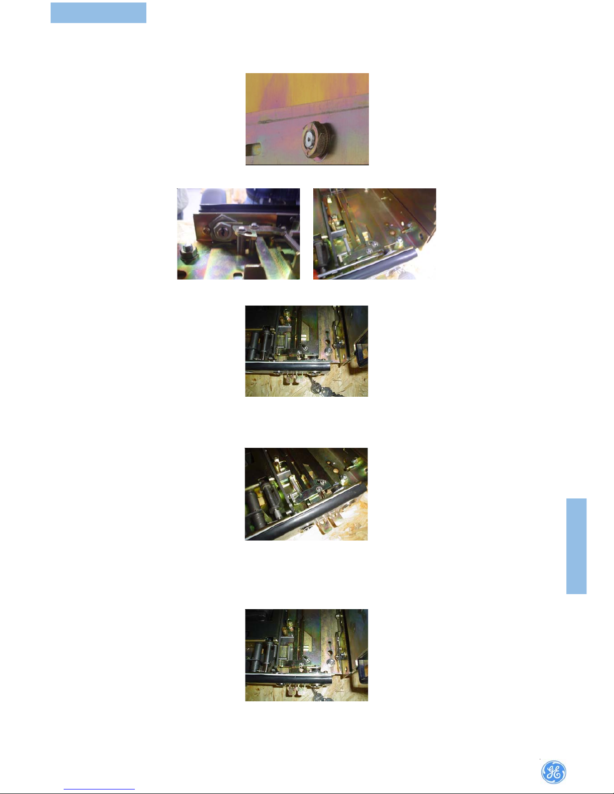
6.9.3.10 Locate the positioners (E) in their place.
6.9.3.11 Fasten the front cover with screw, reset the rods and make sure they
slide freely.
6.9.3.12 Locate the brass spacing ring and the block lever, and screw the
fixing nut(F) of the key lock (D).
6.9.3.10 Positionierungsscheiben(E) einsetzen
6.9.3.11 Frontabdeckung wieder anschrauben, gleichzeitig sicherstellen das
die Verriegelungshebel sich frei bewegen lassen
6.9.3.12 Messing Distanzring, Blockierhebel einsetzen und mit der(F)
Befestigungsmutter festziehen (D)
6.9.3.13 Pull the rods, rotate the key and draw it out; Make sure the safety
shutters
cannot be opened.
6.9.3.13 Verriegelungshebel ziehen Schloss drehen und Schüssel abziehen.
Nun muss es unmöglich sein die Berührungsschutzabdeckung zu öffnen.
FITTING
INSTRUCTION
Page 30

28
BREAKER
G(LH)
6.10 Door interlocking
A door interlock mechanism may be fitted inside the cassette on the right for
L/H hinged door (see in figure) or left for R/H hinged door.
Specify whether door is L/H or R/H hinged when ordering.
Each pack contains an interlock lever, a helical spring, washers and
circlips, (Fig. ‘G’ shows both L/H and R/H sets), also a hasp for fitting to the
door.
6.10.1 Assembly
• Place spring over post protruding from cassette side plate.
• Position interlock lever as shown
• Ensure one end of spring locates below nut the other rests over
small boss on lever.
• Holding lever in position-insert circlip into groove in spring post
then fit two washers over fulcrum boss followed by a circlip to fix.
Note: Right hinged door(DIRHS) item code: 405579
Left hinged door(DILHS) item code: 405578
A) Door interlock lever
B) Fulcrum boss with 2 washer & circlip
C) End of spring locates below nut
D) End of spring fits above boss on inside of lever
E) Circlip
F)
Spring
G) Kit for both L/H and R/H sets
6.10 Türverrriegelung
Eine Türverriegelung kann innen in der Kassette rechts für links anschlagen
Türen und link für rechts anschlagen Türen eingebaut werden. Bei Bestellung
ist die Art de Türanschlages anzugeben.
Jeder Bausatz enthällt Verriegelungshebel, Spiralfeder,
Unterlegscheiben und Sicherungsclips. Der Türhalter gehört ebenfalls
zu Lieferumfang. (Bild ‘G’ zeiget beide Bausätze, für links und Rechts)
6.10.1 Montage:
• Feder auf den hervorstehenden Bolzen an der Kassettenseite schieben
• Hebel wie dargestellt einsetzen.
• Es ist darauf zu achten, dass sich das eine Ende der Feder unterhalb der
Mutter befindet und das andere Ende oberhalb der schmalen Nabe auf dem
Hebel befindet .
• Hebel in Position halten und eine Sicherungsscheibe in die Nut auf dem
Federlagerbolzen einschnappen. Jetzt zwei Scheiben auf die
Stützpunktnabe schieben und ebenfalls mit einer Sicherungsscheibe sichern.
Hinweis: Tür mit Linksanschlag (DIRHS) Artikelnummer: 405579
Tür mit Rechtsanschlag (DILHS) Artikelnummer:405578
A) Verriegelungshebel
B) Stützpunktnabe mit 2 Scheiben und einer Sicherungsscheibe.
C) Feder Ende unterhalb Mutter
D) Federende oberhalb der Nabe auf dem Hebel.
E) Sicherungsscheibe
F) Feder
G) Bausätze für rechts und linksseitigen Anbau
C
E
B
D
F
A
FITTING
INSTRUCTION
G(RH)
Page 31

29
BREAKER
21mm
8mm
LH Hinged
Door Cut-out
F1,3P-27. 5
F1,4P-12 7.5
F2,3P-57. 5
F2,4P-18 7.5
21mm21mm
8mm8mm
LH Hinged
Door Cut-out
LH Hinged
Door Cut-out
F1,3P-27. 5
F1,4P-12 7.5
F2,3P-57. 5
F2,4P-18 7.5
F1,3P-27. 5
F1,4P-12 7.5
F2,3P-57. 5
F2,4P-18 7.5
Linksanschlag
Türausschnitt
6.10.2 To fit Door Interlock
A door interlock mechanism may be fitted inside the cassette on the right for
L/H hinged door or left for R/H hinged door. Specify whether door is L/ H or R/
H hinged when ordering.
6.10.3 Interlock Packs
Each pack contains - an interlock lever, a helical spring, washers and circlips,
(Fig. shows both L/H and R/H sets). A door bracket is also included. (Fig.)
6.10.4 Drill Pattern - Door Bracket Assembly
Door bracket location detail below is for left hand hinged switch board doors
(Fig.). Drill two holes in the door for M5 clearance.
6.10.2 Einbau Türverriegelung
Eine Türverriegelung kann innen in der Kassette rechts für
links angeschlagene Türen bzw. links für rechts
angeschlagene Türen eingebaut werden. Bei Bestellung ist die
Art des Türanschlags anzugeben.
6.10.3 Verriegelungs- Bausätze
Jeder Bausatz enthält Verriegelungshebel, Spiralfeder, Unterlegscheiben und
Sicherungsclips (Fig. 34 zeigt Bausätze für rechts- und linksseitigen Anbau).
Der Türhalter gehört ebenfalls zum Lieferumfang.(Fig.)
6.10.4
Monatge der der Türwinkel
Fig. zeigt die Position des Türhaltes für links angeschlagene Türen.
ZurBefestigung sind zwei Löcher ø 5,2 mm gemäss Skizze zu bohren. Fig.
zeigtdie Position des Türhalters für rechtsangeschlagene Türen. Zur
Befestigung sind zwei Löcher ø 5,2mm gemäss Skizze zu bohren.
1. Fulcrum boss with 2 washers & circlip.
2. End of spring locates below nut.
3. End of spring fits above boss on inside of lever.
4. Circlip.
5. Spring over spring pin
1.
Stützpunktsnabe mit 2
Unterlegscheiben&Sicherungsscheibe.
2. Federende unterhalb der Mutter.
3. Federende oberhalb Nabe auf Innen Seite des
Hebels.
4. Sicherungsscheibe.
5. Feder oberhalb Bolzen.
12
534
FITTING
INSTRUCTION
Page 32

30
BREAKER
Door bracket location detail below (Fig.) is for right hand hinged switch board
doors. Drill two holes in the door for M5 clearance.
6.11 Busbar/Cable Earthing
Optional pack to enable earthing of circuit breaker terminals on busbar or
cable side contains:-
• Isolating contact (cluster) pliers for removal of the main isolating con-
tacts.
• Earthing bar with spring pressured earth contact. The bar is
reversible to fit top or bottom terminal sets **.
• Necessary fixing bolts and washers.
• Anti-trip plate*.
To earth the upper contact set:
(a) Remove the three upper contact clusters at the rear of the circuit
breaker, using the cluster pliers provided (Fig.).
(b) Position earthing bar below the three exposed terminals and loosely
tighten the M10 bolts (into the tapped earthing bar; one bolt per phase.
Tighten to 30Nm.
Note:
1.The spring loaded earthing contact should be facing left when viewed from
rear (Fig.).
2.*Available upon customer request.
3.**Example shown below for the Bottom Terminal sets
Türwinkel (siehe Fig.) dargestellt für Tür mit Linksanschlag. Zwei Löcher für
M5 Befestigungsmaterial müssen gebohrt werden.
6.11 Erdung von Sammelschienen/Kabeln
Das optional erhältliche Set ermöglicht die Erdung der
Leistungsschalteranschlüsse auf Sammelschienen- oder
Kabelseite und enthält:
• Isolierte Kontaktzange zum Abbau der Ausfahrkontakte.
• **Erdungsschiene mit gefederten Erdungskontakt. Die Schiene
ist sowohl an den oberen wie unteren Schalteranschlüssen
montierbar.
• Erforderliche Befestigungsschrauben und Scheiben
• Auslöse -Blockierungsplatte*.
Erdung der oberen Anschlüsse:
(a) Entfernen der oberen Ausfahrkontakte auf der Rückseite des
Leistungsschalters mit der Kontaktzange (Fig.).
(b) Erdungsschiene unterhalb der drei freistehenden Anschlüsse
lose mit den M10 Schrauben fixieren (Gewindelöcher in der
Erdungsschiene vorhanden, eine Schraube pro Phase)
Anziehen mit Drehmoment 30Nm.
Hinweis:
1.Der gefederte Erdungskontakt muss sich links befinden (Schalter von
hinten gesehen, Fig.)
2.*Auf Anfrage
3.**Unten ist ein Beispiel für dieErdung der unteren Anschlüsse gezeigt
21mm
8mm
RH Hinge d
Door Cut-out
F1,3P&4P -41.5
F1,3P&4P -101.5
21mm21m m
8mm8mm
RH Hinge d
Door Cut-out
RH Hinge d
Door Cut-out
F1,3P&4P -41.5
F1,3P&4P -101.5
F1,3P&4P -41.5
F1,3P&4P -101.5
Rechtsanschlag
Türausschnitt
1.Spring loaded earthing contact.
2.Cluster
1.Gefederter Erdungskontakt.
2.Einfahrkontakte
21
FITTING
INSTRUCTION
*Anti-Trip Plate *Auslöse -Blockierungsplatte
**Bottom Terminal sets
F2
Page 33

31
BREAKER
To earth the lower terminal set:
a)Remove lower cluster contacts, reverse the earthing bar so that the M10
tapped holes point downwards, apply bolts and washers as above.
b)The spring loaded earthing contact, still facing left , will locate in the same
position whether upper or lower terminals are earthed and will engage with a
fixed earthed contact block in the cassette when the breaker is racked to the
CONNECTED position (Fig.).
Erdung der unteren Anschlüsse:
a) Entfernen der unteren Ausfahrkontakte, Erdungsschiene umdrehen, so dass
die M10 Gewindelöcher nach unten zeigen. Schrauben und Scheiben wie oben
beschrieben eindrehen und festziehen.
b) Der gefederte Erdungskontakt befindet sich in derselben Position auf der
linken Seite, egal ob die oberen oder unteren Anschlüsse geerdet sind. Er
kontaktiert den festen Erdungskontakt in der Kassette, wird der Schalter in
die Betriebsstellung verfahren (Fig.).
Fixed earthing contact in cassette
6.12 Mechanical operations counter
The optional pack contains an operations counter with fixing screws.This
unit is easily fitted to the inside of the circuit breaker (Directly on the left
side of mechanism as shown in below figure).
• Remove moulded front cover from the circuit breaker.
• Position the operations counter over the two holes provided inside
the cover, ensuring that the indicator face is aligned to show through
the window provided in the cover
• Fix in position using the screws provided.
6.12 Schaltspielzähler
Diese zusätztliche Anbaugerät wird als Set mit Zähler und
Montageschrauben geliefert. Es lässt sich einfach im Inneren des
Leistungsschalter anbauen (linke Seite von Mechnismus siehe Bild)
• Leistungsschalterdeckel abnehmen.
• Den Zähler so über die beiden Löcher auf der Innenseite der Blende
halten, dass die Vorderseite des Zähleres zum Fenster in der Blende
zeigt.
• In dieser Position mit den beiden Schrauben befestigen.
• Beim Aufsetzen des Deckels ist darauf zu achten das der Betätigungshebel
des Zählers in den entsprechenden Hebel im Mechanismus greift.
Hinweis: Der Schaltspielzähler kann nicht zurückgesetzt werden.
FITTING
INSTRUCTION
Feststehender Erdungskontakt in Kassette
MOC with Motor
Operator
MOC without Motor
Operator
Page 34

32
BREAKER
Service operation procedure7 Service Operation
SERVICE
OPERATION
Accessor
y
Check
Switch
Perform some manual openings and closings reloading the springs manually. Check that all
the indicators are working correctly
Shunt trip
Supply the trip (the power voltage must be between 0.7xVn and 1.1xVn) with the switch in
the closed position and check the opening of the switch itself.
Undervoltage release
Close the switch with the release supplied (V=0.85Vn-1.1Vn), turn off the power to the
release and check switch opening. (Operation can also be checked by gradually reducing
the voltage and checking that the opening occurs for 0.35Vn
Closing release
Starting with the switch open and the springs loaded, power the closing release with
V=0.85Vn-1.1Vn and check the switch closing.
Auxiliary contact alarm release tripped
Open by means of the relay (by means of the test unit; see the section on checking the
protection unit) and check the contact change of state
Auxiliary contact signal pull-out switches
On changing from the extracted position to the test and there fore inserted position check
that the contacts change over correctly.
Operation counter Motor command
Perform some Opening/Closing operations and check the indication of the operation
counter. Starting with switch open and springs unloaded, power of the motor (V=0.85Vn and
V=1.1Vn) and check that the springs (signal on the front) are loaded in no longer t
Push-button padlock lock Check the state and correct operation of the lock
Push-button lock OFF Check the state and correct operation of the lock
Padlock lock out Check that with the “tongue” out the crank cannot be put in.
Safety shutter lock Check on the fixed base that with the “tongues” out the shutters cannot be moved
Mechanical interlock
On locking the fork on which the interlock cable operates check that the switch cannot be
operated. (With both interlock devices installed close one, check that the other cannot be
closed and vice versa)
Protection relay See section
Anbaugerät
Prüfun
g
schalter
Einige manuelle Schalthandlungen durchführen. Aus, Spannen und Ein durchführen und die
entsprechenden Signale prüfen
Arbeitsstromauslöser
Den Arbeitsstromauslösen mit geeigneter Spannung (zwischen 0,7 und 1,1 facher
Nennspannung der Spule) versorgen während der Leistungsschalter eingeschaltet ist. Der
Schalter muss auslösen.
Unterspannungsauslöser
Den Leistungsschalter einschalten während der Unterspannungsauslöser versorgt (0,85 bis
1,1 fache Nennspannung der Spule) ist. Nun Die Spannung vom Unterspannungsasulöser
abnehmen, der Leistungsschalter löst aus. Alternativ kann die Versorgungsspannung au
Einschaltspule
Die Einschaltspule mit gespannten, ausgeschaltetem Leistungsschalter an Spannung legen
(0,85 bis 1,1 fache Spulennennspannung). Der Leistungsschalter schaltet zu.
Störmeldeschalter
Leistungsschalter ein, mit Testgerät Auslösung des Mpro herbeiführen. Der
Störmeldeschalter muss die Fehlerauslösung signalisieren.
Positionsmeldeschalter
Den Schaler aus der Trennposition über die Testposition in die Eingefahren Position
verfahren und die Signalgebung entsprechen prüfen
Schaltspielzähler
Einige Schalthandlungen durchführen und prüfen ob der Zähler mit jeder Schalthandlung
weiterzählt. Dies kann manuell oder mit Motor durchgeführt werden. Während dieser
Prüfung die Zustandsanzeigen für Federzustand und Schaltstellung auf unverzögerte Reakt
Druckknopf Verriegelung Auf korrekten Zustand und Funktionalität prüfen
Verriegelung in Aus Auf korrekten Zustand und Funktionalität prüfen
Verriegelung Einfahrtechnik Prüfen das mit herausgezogener Verriegelung die handkurbel nicht gesteckt werden kann
Verriegelung safety shutter
Prüfen das mit herausgezogener Verriegelung die Berührungsschutzabdeckungen nicht
geöffnet werden können
Bouwdenzug Verriegelung zwischen Schaltern
Prüfen das der Leistungsschalter sich nicht zuschalten läst wenn der entsprechende
Bouwdenzug betätigt ist. Oder wenn im Zweischalter system prüfen das sich immer nur ein
Schalter zuschalten lässt.
Mpro Auslöser Siehe Abschnitt in dieser Bedienungsanleitung.
Page 35

33
BREAKER
8 Maintenance
Scope and intervals of testing are to be determined in accordance with the
degree of utilization of the circuit breaker. For ensuring service reliability
and constant readiness for operation it is recommended to observe the
maintenance measures. The individual test and maintenance works can
be determined in detail only by the user. Thus, the instructions given in the
sections and should be considered as recommendations.
8.1 Even »maintenancefree« units are subject to wear and tear as well as
environmental influences. In case of a higher switching frequency and after
several short-circuit interruptions the contact members in particular should
be checked for contact erosion, if necessary, replaced. Breakers which are
only infrequently operated should be maintained at least every 4 years.
When the circuit breakers are used in systems for which special regulations
are valid different maintenance intervals may apply.
Before starting and while performing inspection and maintenance works
the protective measures required by the relevant safety regulations are to
be observed.
8.2A charged operating mechanism is to be discharged before starting the
works. The »OFF« and »NOT CHARGED« switch positions can be checked
via respective windows.
If spare parts should be required for the maintenance works, the original
spare parts are to be used in any case. Strange spare parts could cause a
different behaviour which might result in dangerous situation for the user.
The same is true for the mounting and
demounting of switch accessories: Here also only original accessories are
to be used. Special tools which might possibly be required are listed.
Preventive maintenance
After elapsing half of the mechanical life span (corresponds to the
mechanical life span without maintenance, or electrical life span), depending
on result of inspection and earlier if the occasion should arise, but at the
latest a maintenance should be carried out after 4 years. If the maintenance
is being carried out before reaching half of the mechanical life span, the
contacts have to be replaced if necessary.
MAINTENANCE
8 Wartung:
Wartungsinterwalle und Wartungstiefe sind abhängig vom Grad der
Benutzung des Leistungsschalters. Um eine dauernde Einsatzbereitschaft
zu gewähren, sollten alle Wartungen fristgerecht durchgeführt werden. Da
die Wartungsinterwalle vom Grad der Nutzung abhängen, können die
Wartungsintervalle nur vom Benutzer festgelegt werden, daher sind die
Angaben in den Abschnitten und als Empfehlungen zu betrachten.
8.1 Auch Wartungsfreie Geräte unterliegen Verschleiß. Im Falle von hoher
Schalthäufigkeit oder nach Kurzschussabschaltungen müssen die
Kontaktsysteme überprüft werden und ggf. ausgetauscht werden.
Leistungsschalter die nur selten geschaltet werden sollten mindesten alle
4 Jahre gewartet werden. Für Leistungsschalter die in einer speziell
geregelten Umgebung eingesetzt werden, können sich jeweils andere
Wartungsinterwalle und Tiefen ergeben. Vor Begin jeder Wartung ist
sicherzustellen das die Anlage/der Leistungsschalter den jeweiligen Regeln
entsprechen freigeschaltet ist.
8.2Der Mechanismus des Leistungsschalters sollte vor Beginn der
Wartungsarbeiten entspannt werden. Schalterstellung und der Zustand der
Mechanismusfedern kann an den entsprechenden Anzeigen abgelesen
werden. Für Reparaturen sollten nur Originalersatzteile eingesetzt werden.
Der Einsatz von anderen Ersatzteilen kann zu Fehlfunktionen führen.
Werkzeuge die für die Wartung benötigt werden sind in Abschnitt .
Präventive Wartung
Eine Wartung sollte, nach Erreichen der halben mechanischen Lebensdauer
(Mechanische Lebensdauer ohne Wartung, oder elektrische Lebensdauer),
in Abhängigkeit einer durchgeführten Prüfung oder wenn sich die
Möglichkeit ergibt durchgeführt werden, jedoch nicht später als nach 4
Jahren.
Page 36

34
BREAKER
MAINTENANCE
The switch will not open mechanically
The switch will not open electrically (with opening or minimum voltage uncoupler)
The switch will not close mechanically
The switch will not close electrically
The switch will not close, closes and reopens immediately or closes and reope ns after a short period of service
The moving part will not enter the fixed part (or enters with excessive force)
The moving part cannot be extracted from the fixed part
The m otor wi ll no t recha rg e the spring s
Both switche s can be closed simul taneously in an interlock
One of the two switches in an interlock cannot be closed (with the other switch open)
The closing bobbin, the opening uncouple rs or the motor command are burnt out
Error/fault or alarm message (WARN) on the M-Pro 20 uncoupler di splay unit (or the “Warn/Alarm” LED bl inking)
Irregular pulsing of the “Healthy” LED (or LED off) on the M-Pro 20 uncoupler
Abnormal pulsing (permanently on, permanently off, blinking) of the M-Pro 17+ relay LED
The switch will open if the springs are loaded when it is closed
CAUSES REMEDIES
X
The fixed part is being executed or is in a different
frame to the moving part Change the fixed or moving part
X
The two parts of the lock to prevent incorrect switch
insertion are incompatible
Change the fixed or moving part / replace the block
if fixed and moving part are compatible
X X X X X X Defective kinematic motion Contact GE Consumer & Industrial (page 36)
XX
The opening bobbi n power supply voltage is
inadequate
Measure the power suppl y voltage: it must be
between 0.7Vn and 1.1Vn forcurrent launching
bobbins and between 0.35Vn and 0.70Vn for
minimumvoltage bobbins
X X X X The auxiliary circuit cabling is incorrect
Check the cabling using the wiring diagrams
contained in the installationmanual
X
The opening uncouple r (on current launching or of
minimumvoltage) is positioned incorrectly Check the correct positioning of the uncoupler
X X The minimum voltage uncoupler is faulty Replace the minimum voltage uncoupler
X
The opening uncouple r (on current launching or of
minimumvoltage) is faulty Replace the uncoupler
X X The closing uncoupler is faulty Replace the closing uncoupler
XX
The closing bobbin power supply voltage is
inadequate
Measure the power suppl y voltage: it must be
between 0.85Vn and 1.1Vn
X The closing bobbin is fitted incorrectly
Check the correct positioning of the closing bobbin
in its housing
X X The motor power supply voltage is inadequate
Measure the power suppl y voltage: it must be
between 0.85Vn and 1.1Vn
X
The electronic uncoupler has not been reset after
anintervention Press the electronic uncoupler RESET key
X
The minimum voltage uncoupler is not powered
correctly
Measure the power suppl y voltage: it must be
between 0.85Vn and 1.1Vn
X
The opening bobbi n on current launching is
permanently powered
Cut permanent power to the openi ng bobbin /
check the cabling
X X The kinematic motion springs are unloaded Load the springs (manually or ele ctrically)
X The switch opens due to protection relay cut-in
Check the relay intervention thresholds and, if
necessary, the presence in thesystem of causes
that could determine the cutting in of this relay
X X The interlock is not adjusted correctly Adjust the interlock
X
The extraction operations (page 20) have not been
performedcorrectly
Ensure that: the padlocks have been removed from
the lower panel of theextractable base; the safety
device for operating the crank has been
unlockedand the crank turned from the
DI S CON NE CT ED p os i ti on to the stop on e ; thatth e
springs are unloaded.
X Presence of a fault
Read the fault message on the display unit and
refer to pages 80-85 of thismanual
X The uncoupler is not powered correctly
Check correct operation using a tester or an
auxiliary powe r supply; contactBti cino if the
outcome is not positive
X The relay shows an operating defect Contact M-Pact Plus
Page 37

35
BREAKER
MAINTENANCE
Schalter öffent nicht manuell
Schalter öffent nicht mit Arbeitsstromauslöser oder Unterspannungsauslöser
Schalter schaltet manuell nicht ein
Schalter schaltet elektrisch (Einschaltspule) nicht ein
Schalter schließt nicht, oder schließt aber öffnet sofort wieder, oder schließt aber öffnet nach kurzer Zeit wieder.
Schalter läßt sich nicht oder nur schwer einfahren
Schalter läßt sich nicht ausfahren
Motor spannt die Federn nicht
Beide Schalter einer Verriegelung lassen sich gleichzeitig einshcalten (in Betrieb nehmen)
Ein Scalter in einer Verriegelung läßt sich nicht einschalten (Zweiter Schalter ausgecha ltet)
Einschaltspule, Arbeitsstromauslöser oder Unterspannugsauslöser: Spulen sind durchgebrannt.
Alarm oder Warnungsmeldung auf Mpro 20 Anzeige.
Unregelmäßiges Blinken der Mpro 20 Betriebsazeige
Unregelmäßiges Blinken der Mpro 17 Betriebsazeige (Dauernd an, Dauernd aus, blinken)
Schalter öffnet beim Spannen des Mechanismus
Ursache Lösun
g
X
Schalter passt nicht zum Einschubtraäger
Schalter oder Einschubträger tauschen
X
Schalter codierung stimmt nicht mit dem Einschubträger
überein
Schalter oder Einschubträger tauschen, oder wenn
combination o.k., codierung prüfen (ggf. austauschen)
X X X X X X Interner Mechanismusfehler Technischen Kundendienst ansprechen
XX
Falsche Versorgungsspanung
auslöser und Einschalt Spule zwischen 0,85 und 1,1 mal
der Nennspannung sein, für den
Unterspannungsauslöser zwischen 0,35 und 1,1 mal der
Nenspannung sein.
X X X X Fehelr in Verdrahtung
Verdrahtung mit enthaltenen Verdrahtungsplänen
prüfen.
X
Position der Spulen falsch Positions / Sitz prüfen
X X Unterspannungsauslöser defekt Unterspannungsa uslöser tauschen
X
Einschaltspule oder Arbeitsstromauslöser defekt
Austauschen
X X Einschaltspule defekt Austauschen
XX
Falsche Versorgungsspanung
Prüfe Versorungsspannung, Sie muss für die Einschalt
Spule zwischen 0,85 und 1,1 mal der Nennspannung sein.
X Einschaltspule nicht korrect eingebaut
Sitz und position prüfen.
XX
Spannungsversorgung für den Motor nicht korrekt
Prüfe Versorgungsspannung, soll zwischen 0,85 und 1,1
der Nannspannung sein.
X
Auslöser wurde nach Fehler nicht zurückgesetzt Reset drücken
X
Unterspannungsauslöser Versorgung nicht korrekt Prüfe Versorgungsspannnung
X
Einschaltspule oder Arbeitsstromauslöser wird dauernd
mit Spannung versorgt
Dauernde Versorgung zu den Spulen umspekllen auf
kurzzeit Puls, Verdrahtung prüfen
X X Mechanismus nicht gespannt Schalter Spannen (manuell oder automatisch)
X
Auslöser spricht an
Einstellung des auslösers überprüfen, Fehler in der
elektrischen Anlage ausschließen.
XX
Verriegelung nicht korrekt eingestellt Verriegelung nachjustieren
X
Bediehnungsfehler Sicherstellen: Alle Schlösser entfernt
X Fehler lieget vor
Fehelrmeldung beachten
XAuslöser Defekt
Auslöser mit tester prüfen, Kundendienst ansprechen
wenn der Fehler weiter bestehen bleibt.
X Auslöser defekt Kundendienst ansprechen
Page 38

36
BREAKER
For further information and contract details please contact your local sales representative or After Sales & Service
team:
Austria T +43 1 622 468 00
E service.at@ge.com
Belgium T +32 9 265 21 11
E service.b@ge.com
Germany T +49 180 4437378
E service.g@ge.com
France T +33 3 23 50 70 66/67
E service.f@ge.com
Italy T +39 02 42421
E service.it@ge.com
Netherlands T +31 53 573 03 03
E service.nl@ge.com
Poland
T +48 22 519 42 19
E service.pl@ge.com
Spain T +34 93 736 57 53
E service.e@ge.com
Switzerland T +41 44 804 7070
E service.ch@ge.com
UK T +44 116 2905271
and Ireland E service.uk@ge.com
©2006 General Electric Company. No part of this work may be reproduced or transmitted in any form or by any means, except as permitted in written
license agreement with General Electric Company. General Electric Company has made every reasonable attempt to ensure the completeness and
accuracy of this document. However, the information contained in this document is subject to change without notice, and does not represent a commitment
on the part of General Electric Company. The GE monogram is a registered trademark of General Electric Company.
GEA-D 2006 (02/2006)
On-Site & Emergency Services
•24/7 Emergency assistance
•Installation
•Commissioning, start-up
•Cleaning, lubrication
•Repair, upgrade, retrofit
•Assessment, inspection, audits
•Thermo graphic imaging
Contractual Services
•Maintenance service contracts
•Preventive, planned maintenance
•Resident technical services
•Upgrade management
•Project & site management
•Consultancy and audits
Parts and Repairs
•Spare parts supply
•Repair services
•Retrofit kits for legacy products
•Product replacement / return
•Equipment rentals
The list of products we support in low voltage range include amongst others:
Air Circuit Breaker
•M-Pact I, M-Pact II
•ME…07, MEG, MEY
•ME00/05, M series
•Spectronic SP/SPE, L, S
•GEA RAPID S/SE, Gerapid
•M23, M80
Power Distribution and MCC
•SEK / SEV32 Powercenter + MCC
•GEA Plus
•SV18, SV 90
•Vynconstruct, OK Center
•System4
•CCM
Page 39

BREAKER ETU SKU DIMENSIONS APPENDIX
PICTURE -
M
-
PRO PL US
OPERATOR
CONTROL
PICTURE - M-PRO
OPERATOR
CONTROL
PROTECTIONTESTING
GENERAL
TROUBLE
SHOOTING
1 General (E1 General (E
1 General (E1 General (E
1 General (E
TU)TU)
TU)TU)
TU) 40
1.1
Introduction
1.2 There are three types of Electronic Trip Unit (ETU )
1.3 Functional Features
1.4
Terminolog y (APPENDIX -G )
2 Pictur2 Pictur
2 Pictur2 Pictur
2 Pictur
e(M-PRe(M-PR
e(M-PRe(M-PR
e(M-PR
OPLOPL
OPLOPL
OPL
US)US)
US)US)
US) 41
3 Operator Contr3 Operator Contr
3 Operator Contr3 Operator Contr
3 Operator Contr
olsols
olsols
ols 42
3.1 Setting Current (Ir)
3.2 Short Time Pick up (Im)
3.3 Short Time Delay
3.4 Instantaneous protection 43
3.5 Earth Fault Pickup (If) - OPTIONAL
3.6 Earth Fault Delay - OPTIONAL
3.7 Reset 44
3.8 Navigation Table
4 Pictur4 Pictur
4 Pictur4 Pictur
4 Pictur
e(M-PRe(M-PR
e(M-PRe(M-PR
e(M-PR
O)O)
O)O)
O) 45
4.1 M-PRO 30/40
5 Operator Contr5 Operator Contr
5 Operator Contr5 Operator Contr
5 Operator Contr
olsols
olsols
ols 46
5.1 Button Operation
5.2 Menu Structure 48
6 pr6 pr
6 pr6 pr
6 pr
otectionotection
otectionotection
otection 54
6.1 Earth Fault Protection
6.2 Example to Set unrestricted Earth Fault time to 0.5 Seconds 56
7 T7 T
7 T7 T
7 T
esting Eesting E
esting Eesting E
esting E
TUTU
TU
TU
TU 58
7.1 SELF TEST TRIP
7.2 Powering Mpro Plus/Mpro 30/Mpro 40
7.3 Test Connector & Test box
7.4 Connection
7.5 Applicable for M-ProPlus / M-Pro
7.6 Fitting Instruction - Accessories 59
8 Tr8 Tr
8 Tr8 Tr
8 Tr
ouble Shootingouble Shooting
ouble Shootingouble Shooting
ouble Shooting 64
Page 40

40
ETU
1 General (E1 General (E
1 General (E1 General (E
1 General (E
TU)TU)
TU)TU)
TU)
1.1 Intr1.1 Intr
1.1 Intr1.1 Intr
1.1 Intr
oductionoduction
oductionoduction
oduction
M-PROPlus, M-PRO30 and M-PRO40 are the dedicated protection and
management units for the M-PACT air circuit br eakers and hav e been developed
to meet the most stringent demands of modern circuit pr otection.Designed with
the full benefit of advanced microprocessor technology, the M-PRO protection
and management units offer a comprehensive menu of overload, short circuit
and earth fault protection to satisfy the most enhanced client requirements.
The protection and management system
incorporates the following components:
• Electronic protection relay
• Power current transformers
• Measuring system (Rogowski coil)
The components are separately mounted into the M-PA CT air circuit breaker.
Current transformers pow er the electronic protection relay and the measured
signal is generated by the Rogowski coils on the main phases. The M-PR O
circuitry senses TRUE RMS current with immunity to system disturbances. On
request, the M-PRO protection relay can be permanently powered by an auxiliary
power unit. When the circuit breaker is closed the current transformers ensure
energising power for the pr otection unit.
1.2 Ther1.2 Ther
1.2 Ther1.2 Ther
1.2 Ther
e are ar
e are ar
e ar
e thre thr
e thre thr
e thr
ee types of Electree types of Electr
ee types of Electree types of Electr
ee types of Electr
onic Trip Unit (Eonic Trip Unit (E
onic Trip Unit (Eonic Trip Unit (E
onic Trip Unit (E
TU)TU)
TU)TU)
TU)
1. MPro 17Plus-Rotary switch settings
2. MPro 18Plus-Rotary switch and display features.
3. Mpro 30/40-Digital settings and display feature(only
frame1&2 )
1.3 Functional Featur1.3 Functional Featur
1.3 Functional Featur1.3 Functional Featur
1.3 Functional Featur
eses
eses
es
These ETU offers different protection features, refer APPENDIX-K
1.4 T1.4 T
1.4 T1.4 T
1.4 T
erminologerminolog
erminologerminolog
erminolog
y (APPENDIX -G )y (APPENDIX -G )
y (APPENDIX -G )y (APPENDIX -G )
y (APPENDIX -G )
1 Allgemein (E1 Allgemein (E
1 Allgemein (E1 Allgemein (E
1 Allgemein (E
TU)TU)
TU)TU)
TU)
1.11.1
1.11.1
1.1
EinführEinführ
EinführEinführ
Einführ
ungung
ungung
ung
M-Pro Mikroprozessor Schutz (Protektion) Relais, Mpro Plus, Mpro 30 und Mpro
40 sind speziell für Mpact Leistungsschalter Serie entwick elte Schutzorgane, die
den höchsten Anforderungen modernen Leitungsschutzes entsprechen. Durch
die Benutzung v on Mikropr ozessortechnologie bieten die Mpro Auslöser eine
umfassende, menugesteuerte Auswahl an Überlast-, Kurzschluss- und
Erdschluss- Schutzfunktionen um den Anforderungen unserer Kunden gerecht
zu werden.
Die Auslöseeinheit arbeitet mit folgenden K omponenten:
• Elektronische Auslöseeinheit
• Wandler für Stromversorgung
• Wandler für Strommessung (Rogowsk i Spulen).
Diese Komponenten sind separat in den Mpact Leistungsschalter eingebaut. Die
Strom Wandler übernehmen die Versorgung des elektr onischen Auslösers, die
Rogowski Spulen auf den Hauptstrombahnen liefern das Messsignal. Die Auslöse
Einheit führt eine Effektivwertmessung durch die immun gegen
Systemst örungen ist .Der Auslöser kann, wenn gewünscht auch extern versorgt
werden. Wenn diese externe Versorgung nicht vorliegt arbeitet der Auslöser
Selbstv ersor gt sobald ausreichend primär Strom fließt .
1.2 es gibt 3 T1.2 es gibt 3 T
1.2 es gibt 3 T1.2 es gibt 3 T
1.2 es gibt 3 T
ypen vypen v
ypen vypen v
ypen v
on Auslösern:on Auslösern:
on Auslösern:on Auslösern:
on Auslösern:
1 Mpro 17 Plus: Drehschalter zur Parametereinstellung
2 Mpro 18 Plus: Drehschalter und Digitalanzeige
3 Mpro 30/40: Digitale Eingabe und Digitalanzeige (Nur
Baugröß e 1 und 2)
1.3 Funk1.3 Funk
1.3 Funk1.3 Funk
1.3 Funk
tionentionen
tionentionen
tionen
Die Mpr
o Auslöser bieten verschieden Funktionen wie im
(Anhang - K) aufgelistet.
1.41.4
1.41.4
1.4
TT
TT
T
erminologieerminologie
erminologieerminologie
erminologie
((
((
(
Siehe Anhang - GSiehe Anhang - G
Siehe Anhang - GSiehe Anhang - G
Siehe Anhang - G
))
))
)
GENERAL
Page 41

41
ETU
1
2
3
4 10
9
8
6
5
7
111
222
333
444 1010
999
888
666
555
777
1 Long time setting
2 Short time setting
3 Unrestricted earth fault setting
4 Test connector
5 Instantaneous setting
6 Reset switch
7 Short time delay
8 curve followed
9 Unrestricted earth fault delay setting
10 Healthy light emitting diode
1.Überlasteinstellung
2.Kuzschlußansprechwe rt (S-Kanal)
3.Erdschlußansprechwert
4.Stecksockel Testgerät
5.Kuzschlußansprechwert (K-Kanal)
6.Resettaste
7.Kurzschlußverzögerung (S-Kanla)
8.Kurvenform
9.Erdschlußverzörgerung
10.Betriebsanzeige.
2 Pictur2 Pictur
2 Pictur2 Pictur
2 Pictur
e(M-PRe(M-PR
e(M-PRe(M-PR
e(M-PR
OPLOPL
OPLOPL
OPL
US)US)
US)US)
US)
Example - M-PRExample - M-PR
Example - M-PRExample - M-PR
Example - M-PR
O 17 PlusO 17 Plus
O 17 PlusO 17 Plus
O 17 Plus
PICTURE -
M
-
PRO PL US
Page 42

42
ETU
3 Operator Contr3 Operator Contr
3 Operator Contr3 Operator Contr
3 Operator Contr
olsols
olsols
ols
All operator controls are pr esented on the M-PRO Plus fr ont panel. The switches
may be adjusted at any time, whether the breaker is open or closed, and powered
or not.
31 Setting Curr31 Setting Curr
31 Setting Curr31 Setting Curr
31 Setting Curr
ent (Ir)ent (Ir)
ent (Ir)ent (Ir)
ent (Ir)
This is the pick-up current for long-time protection. It is set as a fraction of the
breaker rating (In) to values ranging from 0.4In to 1.0In in steps of 0.1In.
3.2 Shor3.2 Shor
3.2 Shor3.2 Shor
3.2 Shor
t Time Pickt Time Pick
t Time Pickt Time Pick
t Time Pick
up (Im)up (Im)
up (Im)up (Im)
up (Im)
This is the pick-up current for short time protection (Im). It is set as a multiple of
the setting current (Ir). Switch positions are provided at 2.0xIr, 3.0xIr, 4.0xIr, 6.0xIr,
8.0xIr, 10xIr and 12xIr.
3.3 Shor3.3 Shor
3.3 Shor3.3 Shor
3.3 Shor
t Time Delayt Time Delay
t Time Delayt Time Delay
t Time Delay
The short time delay can be set to instantaneous, 0.1s 0.2s, 0.4s, 0.6s, 0.8s or 1.0s
3 Bedienelemente3 Bedienelemente
3 Bedienelemente3 Bedienelemente
3 Bedienelemente
Alle Bedienelemente sind auf der Frontplatte des MPRO Plus leicht zugänglich
angebracht . Die Einstellknöpfe können jederzeit betätigt werden, unabhängig
vom Betriebszustand des Schalters.
3.1 Einstellung S3.1 Einstellung S
3.1 Einstellung S3.1 Einstellung S
3.1 Einstellung S
trtr
trtr
tr
om (Ir)om (Ir)
om (Ir)om (Ir)
om (Ir)
Der Ansprechwert für den Überlastschutz wird als Teil des Bemessungsstromes
In im Bereich v on 0,4 bis 1,0 x In in Schritten von 0,1x In eingestellt .
3.2 K3.2 K
3.2 K3.2 K
3.2 K
urur
urur
ur
zschlussschutz-Ansprzschlussschutz-Anspr
zschlussschutz-Ansprzschlussschutz-Anspr
zschlussschutz-Anspr
echwechw
echwechw
echw
erer
erer
er
t (Im)t (Im)
t (Im)t (Im)
t (Im)
Der Kurzschlussschutz-Ansprechwert ist einstellbar als Vielfaches des Stromes
Ir. Einstellungen bei 2,0x Ir, 3,0x Ir, 4,0x Ir, 6,0x Ir, 8,0x Ir, 10x Ir und 12x Ir sind
möglich.
3.3 K3.3 K
3.3 K3.3 K
3.3 K
urur
urur
ur
zeitvzeitv
zeitvzeitv
zeitv
erer
erer
er
zögerzöger
zögerzöger
zöger
ungung
ungung
ung
Das Ansprechen des Kurzschlussauslösers kann zwischen INST (unverzögert),
0,1s, 0,2s, 0,4s, 0,6s, 0,8s und 1s verzögert werden.
Strom xln
Strom xln
Strom xln
OPERATOR
CONTROL
Page 43

43
ETU
3.5 Ear3.5 Ear
3.5 Ear3.5 Ear
3.5 Ear
th Fth F
th Fth F
th F
ault Pickault Pick
ault Pickault Pick
ault Pick
up (Ifup (If
up (Ifup (If
up (If
) - OPTIONAL) - OPTIONAL
) - OPTIONAL) - OPTIONAL
) - OPTIONAL
This is the pick-up current for earth fault protection. It is set as a fraction of the
breakers rating (Ir). Switch positions are provided at OFF, 0.4In, 0.6In, 0.8In and
1.0In. The OFF position disables earth fault protection.
3.6 Ear3.6 Ear
3.6 Ear3.6 Ear
3.6 Ear
th Fth F
th Fth F
th F
ault Delay - OPTIONALault Delay - OPTIONAL
ault Delay - OPTIONALault Delay - OPTIONAL
ault Delay - OPTIONAL
The fixed-time earth-fault delay can be set to instantaneous, 0.1s 0.2s, 0.4s, 0.6s,
0.8s or 1.0s
3.5 Er3.5 Er
3.5 Er3.5 Er
3.5 Er
dschlusschutz-Ansprdschlusschutz-Anspr
dschlusschutz-Ansprdschlusschutz-Anspr
dschlusschutz-Anspr
echwechw
echwechw
echw
erer
erer
er
t (Ift (If
t (Ift (If
t (If
) - Optional) - Optional
) - Optional) - Optional
) - Optional
Der Erdschlussschutz-Ansprechwert ist einstellbar als Vielfaches des Stromes In.
Mögliche Einstellungen sind AUS, 0,4x In, 0,6x In, 0,8x In und 1,0x In. In der Stellung
OFF ist dieser Schutz deaktiviert.
3.6 Er3.6 Er
3.6 Er3.6 Er
3.6 Er
dschlussschutz-Zeitvdschlussschutz-Zeitv
dschlussschutz-Zeitvdschlussschutz-Zeitv
dschlussschutz-Zeitv
erer
erer
er
zögerzöger
zögerzöger
zöger
ung - Optionalung - Optional
ung - Optionalung - Optional
ung - Optional
Die vorgegebene Erdschlussschutz – Zeitve rzögerung kann eingestellt werden
zwischen INST (unve rzögert), 0,1s, 0,2s, 0,4s, 0,6s, 0,8s und 1s.
Strom xln
Strom xln
3.4 Instantaneous pr3.4 Instantaneous pr
3.4 Instantaneous pr3.4 Instantaneous pr
3.4 Instantaneous pr
otectionotection
otectionotection
otection
• The instantaneous-protection function protects the distribution system against
solid short-circuits. Contrary to the short-time protection function, the tripping
delay for instantaneous protection is not adjustable.
• The trip signal is sent to the circuit breaker as soon as current exceeds the set
value. This function is based on peak measurements.
• User can choose the instantaneous pickup as OFF, 2, 3, 4, 6, 8, 10. For OFF
setting instantaneous will be disabled.
Note: - It is recommended not to turn Inst OFF
3.43.4
3.43.4
3.4
UnvUnv
UnvUnv
Unv
erer
erer
er
zögerzöger
zögerzöger
zöger
ter Kter K
ter Kter K
ter K
urur
urur
ur
zschlussschutzzschlussschutz
zschlussschutzzschlussschutz
zschlussschutz
• Der Unverzöger te Kurzschluss Kanal schützt die Verteilung gegen hohe
Kurzschlussströme. Im Gegensatz zum Kurzeitschutz ist die Auslösev erzöger ung
für den Kurzschlussschutz nicht einstellbar.
• Der Auslöseimpuls wird sofort , bei überschreiten eines Gr enzwertes erzeugt .
Diese Messung basiert auf einer Spitzenstrommessung.
• Die Grenzwerte können eingestellt werden zu: Aus (OFF), 2, 3, 4, 5, 8, 10. In
Stellung Aus ist der Kanal abgeschaltet. Es ist empfohlen diesen Kanal nicht
abzuschalten.
IN S T
Strom xln
OPERATOR
CONTROL
Page 44

44
ETU
3.7 R3.7 R
3.7 R3.7 R
3.7 R
eseteset
eseteset
eset
In the event of a fault, the M-PRO 17+ will trip the bre aker and the reset button will
eject from its normally flush position. The reset button must be pushed home
before the circuit breaker can be re-closed.
3.7 Rückstellung3.7 Rückstellung
3.7 Rückstellung3.7 Rückstellung
3.7 Rückstellung
Im Fehlerfall löst der M-PRO den Leistungsschalter aus und der Rückstellknopf
springt aus seiner Ruhestellung heraus. Der Rückstellknopf muss gedrückt
werden, bevor der Leistungsschalter wieder eingeschaltet werden kann.
3.8 Navigation T3.8 Navigation T
3.8 Navigation T3.8 Navigation T
3.8 Navigation T
ableable
ableable
able
(1) Phase curr(1) Phase curr
(1) Phase curr(1) Phase curr
(1) Phase curr
ents:ents:
ents:ents:
ents:
L1 phase current (Amps) L2 phase current (Amps) L3 phase current (Amps)
Range is from 0 to 9999A.
If current is less than 8% of breaker rating then it shall be displayed as <####A.
If current is greater than 9999 then it will be displayed as 9999 in Frame 1 and
Frame 2
.
If breaker is open then the currents will be displayed as 0.
3.8 Navigation3.8 Navigation
3.8 Navigation3.8 Navigation
3.8 Navigation
(1)(1)
(1)(1)
(1)
PhasenstrPhasenstr
PhasenstrPhasenstr
Phasenstr
ömeöme
ömeöme
öme
L1 Phasenstrom [A] L2 Phasenstrom [A] L3 Phasenstrom [A]
Anzeige v on 0 bis 9999 Ampere.
Wenn der Str om kleine als 8% des Schalternennstromes ist wird dies angezeigt
als <####A .
Wenn der Strom größer ist als 9999A dann wird der Strom in Baugröß e 1 und 2
als 9999A angezeigt . Ein Strom von 15000A wird als „15k” angezeigt.
Wenn der Schalter offen ist wird der Strom mit „0000" angezeigt.
2)Neutralleiter.- und Erdschlussströme;
Neutralleiterströme werden wie folgt
dargestellt:
3) Schalter Zustand
4) Ereignis Protokoll
OPERATOR
CONTROL
Page 45

45
ETU
4 Pictur4 Pictur
4 Pictur4 Pictur
4 Pictur
e(M-PRe(M-PR
e(M-PRe(M-PR
e(M-PR
O)O)
O)O)
O)
The user interface on the panel M-PRO 30/40 unit is used for operator control
4 Mpr4 Mpr
4 Mpr4 Mpr
4 Mpr
o Einführo Einführ
o Einführo Einführ
o Einführ
ungung
ungung
ung
Die Bedienelemente auf dem Auslöser ermöglichen die Einstellung der Parameter.
4.1 M-PR4.1 M-PR
4.1 M-PR4.1 M-PR
4.1 M-PR
O 30/40O 30/40
O 30/40O 30/40
O 30/40
4.14.1
4.14.1
4.1
Bild MprBild Mpr
Bild MprBild Mpr
Bild Mpr
o Auslösero Auslöser
o Auslösero Auslöser
o Auslöser
1 Overload/short-circuit protection curve incorporating 7 red
LED’s;indication of fault type.
2 Earth fault protection curve incorporating 2 red LED’s for fault
indication.
3 LCD 2 Line display for clear indication of menus,settings, recorded
information.
4 Warn / Alarm LED
5 Healthy LED
6 Selectable manual- / Automatic - Reset button.
7 Four button tactile key pad.
8 Multi pin socket for test box and/or portable power box.
PICTURE - M-PRO
2
7
3
4
5
6
1
8
Example - M-PRExample - M-PR
Example - M-PRExample - M-PR
Example - M-PR
O 30/40O 30/40
O 30/40O 30/40
O 30/40
1. Auslösekur ve mit 7 LED’s um den Betriebzustand
anzuzeigen
2. Erdschlussschutz Kurve mit 2 LED’s zur anzeige des
Betriebszustands
3. LCD (Digitalanzeige). Zweizeilige Anzeige zum darstellen der
Einstellungen und Betriebszustände.
4. Warnung /Alarm LED
5. Betriebszustand Anzeige (zeigt an ob der Auslöser selbst
Störungsfrei ist)
6. Wahlschalter manuelles oder automatisches Rücksetzen.
7. Drucktasten zur Menusteuerung
8. Anschluss für Testgerät
Page 46

46
ETU
5 Operator Contr5 Operator Contr
5 Operator Contr5 Operator Contr
5 Operator Contr
olol
olol
ol
5.1 Button Operation5.1 Button Operation
5.1 Button Operation5.1 Button Operation
5.1 Button Operation
UP moves you up (-) the Menu list you are in.
DOWN moves you down (¯) the Menu list you are in.
ESCAPE moves you out (¬) to the “Parent” Menu.
SELECT moves you into (®) a new “Child” Menu
MODIFY (SELECT+DOWN pressed together)
Use these buttons to access the 4 menu levels within the MPRO menu structure
as detailed in table 1.(PAGE-50)
5 Menüführ5 Menüführ
5 Menüführ5 Menüführ
5 Menüführ
ungung
ungung
ung
5.1 T5.1 T
5.1 T5.1 T
5.1 T
asten Funkasten Funk
asten Funkasten Funk
asten Funk
tiontion
tiontion
tion
UP: Erzeugt im Menu eine Bewegung nach oben
DOWN: Er zeugt im Menu eine Bewegung nach unten
ESCAPE: Spr ung in das übergeordnete Menu
SELECT : Sprung in das ausgewählte Menu
MODIFY: (Select + Down gleichzeitig gedrück t)
Mit diesen Tasten können alle vier Menuniveaus des Mpro Auslösers erreicht
werden. Die Menustruktur ist in Tabelle 1 auf Seite 50 dargestellt
5.1.15.1.1
5.1.15.1.1
5.1.1
Long Time settingsLong Time settings
Long Time settingsLong Time settings
Long Time settings
The Mpro30/40 user interface provide the feature to change the Long time Pick
up levels From 0.4 to 1.0 in steps of 0.1 .
Long time Delay Settings:
There are 5 differ ent types of LT curves and each curve has 16 settings. so in
total we will have 5*16=60 curves available.The five different types of LT curves
are:
1) Standard inve rse pr otection
2) Very inverse and Long-time inverse protection
3) Extremely inverse protection (General Purpose)
4) Extremely inverse protection (Motor Protection)
5) HV fuse compatible protection
5.1.15.1.1
5.1.15.1.1
5.1.1
ÜberlasteinstellungÜberlasteinstellung
ÜberlasteinstellungÜberlasteinstellung
Überlasteinstellung
Der Mpro Auslöser erlaubt die Einstellung des Grenzwertes von 0,4 bis 1,0
fachen Nennstrom in Schritten von 0,1. Verzögerungseinstellungen:
Es gibt 5 verschiedene Varianten von Auslösekurven, jede von diesen Kurv en
hat 16 Einstellungen. Die 5 V arianten sind folgende:
1. SI (Standart Invertiert) Kurve
2. Stark invertierte Kurve
3. EI (Extr em Invertiert) Kurve (Leitungsschutz)
4. EI (Extrem Invertiert) Kur ve (Motor schutz)
5. HV Sicherungsähnlicher Schutz
Long Time Dela
y
Long Time
LT PU
LT DLY
INV. ST. PU
INV. S T. D LY
FIX. S T. P U
FIX. ST. DLY
5.1.25.1.2
5.1.25.1.2
5.1.2
ShorShor
ShorShor
Shor
t time settings (Invt time settings (Inv
t time settings (Invt time settings (Inv
t time settings (Inv
erer
erer
er
se)se)
se)se)
se)
The user can change the Short Time pick up and delay settings. Inverse Time
Short Cir cuit pick up can be set to 1.5,2.0,3.0,4.0, 6.0, 8.0,10.0,12.0 x Ir.
5.1.25.1.2
5.1.25.1.2
5.1.2
K K
K K
K
urur
urur
ur
zzeitschutz (Kzzeitschutz (K
zzeitschutz (Kzzeitschutz (K
zzeitschutz (K
urur
urur
ur
zschlussschutz) (Invzschlussschutz) (Inv
zschlussschutz) (Invzschlussschutz) (Inv
zschlussschutz) (Inv
erer
erer
er
tiertier
tiertier
tier
t)t)
t)t)
t)
Der Auslösegrenzwert kann . zu 1.5, 2, 3, 4, 6, 8, 10, 12 fachen vom eingestellten
Strom.
Short Time Dela
y
Short Time
OPERATOR
CONTROL
Page 47

47
ETU
5.1.35.1.3
5.1.35.1.3
5.1.3
ShorShor
ShorShor
Shor
t time settings (Fixed)t time settings (Fixed)
t time settings (Fixed)t time settings (Fixed)
t time settings (Fixed)
Fixed Time Short Circuit Pick up can be set to 1.5, 2, 3, 4,6, 8, 10, 12 and 14* x
Ir*14x Ir is only available for Frame 1
5.1.3 K5.1.3 K
5.1.3 K5.1.3 K
5.1.3 K
urur
urur
ur
zzeitschutz (Kzzeitschutz (K
zzeitschutz (Kzzeitschutz (K
zzeitschutz (K
urur
urur
ur
zschlussschutz) (Fest)zschlussschutz) (Fest)
zschlussschutz) (Fest)zschlussschutz) (Fest)
zschlussschutz) (Fest)
Feste Kurzeitauslösung kann eingestellt we rden zu: 1.5, 2, 3, 4, 6, 8, 10, 12 and 14
fachen vom eingestellten Nennstrom. 14 fach ist nur für Baugröße 1 v erfügbar.
5.1.4 Ear5.1.4 Ear
5.1.4 Ear5.1.4 Ear
5.1.4 Ear
th Fth F
th Fth F
th F
ault Settingsault Settings
ault Settingsault Settings
ault Settings
UEF Pickup can be set to Off, 0.1-1.0 of In in steps of 0.1
UEF Fixed time delay can be set to Inst ., 0.1 - 1.0 sec in steps of 0.1 REF Pickup
can be set to Off, 0.1-1.0 of In in steps of 0.1
SEF Pickup can be set to Off, 0.1-1.0 of In in steps of 0.1
REF and SEF Delay settings can be inst,0.1s,0.2s,0.3s,0.4s,0.5s,
0.7s,0.8s,0.9s,1.0s.
REF and SEF Cropping delay can be set to Off, 1.5,2.0,3.0,4.0, 5.0,6.0
5.1.4Er5.1.4Er
5.1.4Er5.1.4Er
5.1.4Er
dschluss Einstellungen:dschluss Einstellungen:
dschluss Einstellungen:dschluss Einstellungen:
dschluss Einstellungen:
UEF (unrestricted Ear th fault = Abgangseitiger Erdschlussschutz) Ansprechwerte
können von 01 bis 1,0 mal Nennstrom in 0,1
Schritten eingestellt werden. Die UEF Auslöseverzögerung kann eingestellt werden
auf:: INST (Keine Ve rzögerung), 0,1 bis 1,0 in Schritten von 0,1.
REF (Restricted Erthfault = Einspeiseseitiger Erdschlussschutz) Ansprechwerte
können von 0,1 bis 1,0 mal Nennstrom eingestellt we rden in Schritten von 0,1 oder
mit OFF ausgeschaltet werden.
SEF (Standby Ear th fault = Beidseitiger Erdschlussschutz)
Ansprechwe rte sind von 0,1 bis 1,0 mal Nennstrom in
Schritten von 0,1 einstellbar oder mit OFF ausschaltbar.
REF und SEF Auslöseverzögerung ist einstellbar auf:
Inst(=Unverzögert); 0,1; 0,2; 0,3; 0,4; 0,5; 0,6; 0,7; 0,8; 0,9
oder 1 Sekunde.
REF und SEF I
2
t Verzögerung ist einstellbar auf: Off; 1,5;
2; 3; 4; 5 und 6 mal I/In.
5.1.5 HSISC/MCR settings:
HSISC settings can be set to 30 to 80kA in steps of 5kA.(MPRO 30/40)
MCR settings can be set to 30 to 50kA in steps of 5kA.(MPRO 30/40, MPRO 17
PLUS &18 PLUS)
5.1.5 HSIC/MCR5.1.5 HSIC/MCR
5.1.5 HSIC/MCR5.1.5 HSIC/MCR
5.1.5 HSIC/MCR
HSIC (High Short Circuit interruption Channel = Hoch-Kurzschlussstrom Kanal)
HSIC kann von 30 bis 80kA in Schritten von 5kA eingestellt werden.(MPRO 30/40)
MCR (Make Current Release = Einschaltstrom Auslöser):
MCR ist von 30 bis 50kA einstellbar (MPRO 30/40, MPRO 17PLUS &18 PLUS)
Sh o r t T i m e
Delay(Fixed)
Short T ime
(Fixed)
I
f
HS I S C / M C R
OPERATOR
CO
NTR
O
L
Page 48

48
ETU
5.2 Menu S5.2 Menu S
5.2 Menu S5.2 Menu S
5.2 Menu S
trtr
trtr
tr
uctuructur
uctuructur
uctur
ee
ee
e
There are four levels within the M-PRO menu structure, the main three are described below. Only those menus specified at the time of ordering will be factor y set into
M-PRO hence not all of the following menus will be available.
11
11
1
Options for M-PROptions for M-PR
Options for M-PROptions for M-PR
Options for M-PR
O 30O 30
O 30O 30
O 30
22
22
2
Options for M-PROptions for M-PR
Options for M-PROptions for M-PR
Options for M-PR
O 40O 40
O 40O 40
O 40
OPERATOR
CONTROL
Level 1 Menu Le vel 2 Me nu Level 3 Menu Level 4 Menu
I set e.
g
: 4 0% I n
Curve Type e.g: Standard Inverse
Curve Speed e.g: Curve 6
Co ol in
g
Time e.g: In stant an eous
Inverse Short Circuit Current e.g : 4 x Iset
Fixed Short Circuit Current e.g: 6 x Iset
Fixed Short Dela
y
e.g: 300m s
Neu tral Rating e.g: Fu lly R ated
Pha se R ota tion e.g : R YB Clockwis e
REF Current e.g: 10% In
REF Ala rm e.
g
: O N
UEF Cur ren t e.g : 30% In
UEF Trip Time e.g: 400m s
UEF Cro
pping
e.g: 2 .5
SEF Current e.g: 50% In
SEF Trip Time e.g: 5 00ms
SEF Cro
pping
e.g: 4
SEF Int ertrip e.g : O N
Load Monitoring e.g: Load shedding/pretrip alarm
Start Sheddin
g
e.g: 9 5% x Is et
Stop Shedding e.g: 80% x Iset
Red Ylw Blue (A)
Red Ylw Blue (% I set
)
Neutral (% I set)
Highest Phase (A)
P eak RMS Ph as e (A )
SEF Current (A)
REF Current (A)
UEF Current (A)
Thermal Re
g
ister (%)
In put 1 e.g : wa rn
In put 2 e.g : wa rn
In
p
ut 3 e.g: wa rn
In put 4 e.g : wa rn
Existi ng Faults e.g : N o Faults
Histor
y
of Tripse.
g
: O ve rloa d T rip on Red
Breaker position e.g: Closed
Co ntact L i fe e.g : 10%
Tota l Life e.
g
: 7 0%
No. of Operations e.g : 3020
M-PRO Status Powered Up Time e.g: 500 minutes
Software Issue e.
g
: 5201 D06, 6A 4AH
EPROM Name e.g : M-P RO 5201 D 6
PAMM Status PAMM Identity e.g: 40/F/A9A4701H
Baud R ate e.g : 9 600
Link Scan Range e.g: 0.01 to 0.03
Link Scan Time e.g: 44 seconds
Link Ti meo ut s e.g : 2
CR C E rrors e.
g
: 0
Link A dd res s e.g : 3
Baud Rate Setup e.g: automatic
Li nk Fa il Ac t ion e .
g
: wa rn
Fa ult Cr nt Type e.g : O ve r Cur r ent
O ve r Cr nt Level e.g : 2 x Is et
Ea rth Cr nt Level e.
g
: 2 0%
Activate Test e.g: Start Test
Comm unic atio ns
2
Link Status
Link Setup
Test Mode(available when test box is
inserted and switched on)
Faults
System Status Breaker Status
Software Status
Ammeters
Input Settings
1, 2
Protection Curve Settings
Earth Protection
1,2
Loa d Monitori ng
1,2
Page 49

49
ETU
5.2 Menüstr5.2 Menüstr
5.2 Menüstr5.2 Menüstr
5.2 Menüstr
ukuk
ukuk
uk
turtur
turtur
tur
Innerhalb der Menüstruktur existieren vier Ebenen. Die Hauptebenen sind unten beschrieben. Nur die bestellten Menüs werden werksseitig im M-PR O
gespeichert, desw egen sind nicht alle der folgenden Menüs vorhanden.
11
11
1
Optionen für M-PROptionen für M-PR
Optionen für M-PROptionen für M-PR
Optionen für M-PR
O 30O 30
O 30O 30
O 30
22
22
2
Optionen für M-PROptionen für M-PR
Optionen für M-PROptionen für M-PR
Optionen für M-PR
O 40O 40
O 40O 40
O 40
OPERATOR
CONTROL
Menü Ebene 1 M enü Ebene 2 Menü E bene 3 Menü Ebene 4
Stromeinstellun
g
I set
z.B. 40% In
Kurventyp z. B. Normal fallend
Ku rve n Trä ghe it sg ra d z. B. Ku rv e 6
Kü hl zei t
z. B. unver z ögert
Ku rz sch lu sss tro m z.B. 4x Iset
Fest er Kurz schl us sstr om z.B. 6x Iset
Fest e Ku rz ze i tv erz ö
g
erun
g
z.B. 300ms
Wert Neutralleiter z. B. 100%
Drehrichtung Phasen z.B. L1/L2/l3 rechts
Typ REF z.B. 10% In
Alar m REF z. B. EIN
Typ UEF z.B. 30% In
Auslösezeit U EF z.B. 400ms
I²t Charakteristik UEF z.B. 2,5
Typ SEF z.B. 50%In
Auslösezeit SE F z.B. 500ms
I²t Charakteristik SEF z.B. 4
wechsel seitige A uslös ung z.B. EI N
Last über wachun g z.B. L astüb er wachun g/
Vo ra la r m Aus lö sun
g
Last abwurf Start z.B. 95% x Iset
L1/L2/L3 (A)
L1/L2/L3 (% I set)
Neutral (%Iset)
Höchste Phase(A)
Scheitelwert RMS
Phase (A)
Strom (A) SEF
Strom (A) REF
Strom (A) UEF
Eing an g 1 z. B. Warnu ng
Eing an g 2 z. B. Warnu ng
Ein
gang
3 z.B. Warnun
g
Eing an g 4 z. B. Warnu ng
Existieren de Fehler z. B. keine Feh ler
Auslösevor
g
eschichte z. B. Überlastauslösung in L1
Schalterstellung z.B. geschlossen
Schaltstücklebensdauer z.B. 10%
g
es am te Le b ens dau er z.B. 70%
Anzahl der Sc hal t ungen z.B. 3020
M-P RO Status Betrieb sd au er z.B. 500 Mi nuten
S of t ware status Softwa re Version z .B. 5201 D0 6, 6A4 AH
EPROM Name z.B. M-PRO 5201 D6
PAMM Status PAMM Identität z.B. 40/F/A9A4701H
Ba ud rate z. B. 960 0
Verbi ndung Scan bereich z.B. 0, 01 b is 0,03
Verbindung Scanzeit z.B. 44 Sekunden
Verbindung Timeout z.B. 2
CR C F e h l er z . B. 0
Ver bi ndun gsadres se z.B. 3
Baud ra tenein stellun g z.B. au toma ti sch
Ver bi nd un
g
fehlerhafte z.B. Warnun
g
Fehlerstromtyp z.B. Überlast
Größe Überlaststrom z.B. 2x Iset
Größe z.B. 20%
Erdschlussstrom
Kommunikation² Verbindungsstatus
Verbindungsaufbau
Te stm odus ( ve rfüg ba r, w en n T est gerä t
eingesteckt und angeschaltet ist)
Fehler
Syste mstatus Sch al ters tatus
Ammeters
Ei ns tel lung en Eingäng e
1,2
Schutz Kurv ena uswa hl
Erdschlussschutz
1,2
La stü ber wach ung
1,2
Page 50

50
ETU
Operating M-PROperating M-PR
Operating M-PROperating M-PR
Operating M-PR
O30/40O30/40
O30/40O30/40
O30/40
When M-PRO is first energised:
The green ‘Healthy’ LED will light indicating that (a) power is present, (b) The unit is functioning normally. This will remain lit at all times when M-PRO is energised unless
a fault is present . Refer to M-PRO menu structure when the instructions below are carried out .
The following will explain how to set the M-PRO to a short time delay of 0.8 sec.
For the other settings, the procedur e is EXACTLY the same. Refer to the menu structure above.
- First step, go to the
prpr
prpr
pr
otectionotection
otectionotection
otection menu
If the M-PRO was displaying the ammeters page, you will have to: If the M-PRO was displaying the Fault page, you will hav e to:
PrPr
PrPr
Pr
essess
essess
ess
and the M-PRand the M-PR
and the M-PRand the M-PR
and the M-PR
O will displayO will display
O will displayO will display
O will display
Then go to the
Fixed S / C TimeFixed S / C Time
Fixed S / C TimeFixed S / C Time
Fixed S / C Time Sub - menu
PrPr
PrPr
Pr
essess
essess
ess
and the M-PRand the M-PR
and the M-PRand the M-PR
and the M-PR
O will displayO will display
O will displayO will display
O will display
ThenThen
ThenThen
Then
ThenThen
ThenThen
Then
ThenThen
ThenThen
Then
7 times7 times
7 times7 times
7 times
PrPr
PrPr
Pr
essess
essess
ess
and the M-PRand the M-PR
and the M-PRand the M-PR
and the M-PR
O will displayO will display
O will displayO will display
O will display
ThenThen
ThenThen
Then
ThenThen
ThenThen
Then
ThenThen
ThenThen
Then
EscapeEscape
EscapeEscape
Escape
Up
SelectSelect
SelectSelect
Select
SelectSelect
SelectSelect
Select
DownDown
DownDown
Down
InvInv
InvInv
Inv
erer
erer
er
se S/C Crntse S/C Crnt
se S/C Crntse S/C Crnt
se S/C Crnt
= 4 x I SE= 4 x I SE
= 4 x I SE= 4 x I SE
= 4 x I SE
T 1600AT 1600A
T 1600AT 1600A
T 1600A
Cooling timeCooling time
Cooling timeCooling time
Cooling time
= Instant= Instant
= Instant= Instant
= Instant
O / L CurO / L Cur
O / L CurO / L Cur
O / L Cur
vv
vv
v
eses
eses
es
= C03, 8.00s @ Iset= C03, 8.00s @ Iset
= C03, 8.00s @ Iset= C03, 8.00s @ Iset
= C03, 8.00s @ Iset
CurCur
CurCur
Cur
vv
vv
v
e Te T
e Te T
e T
ypeype
ypeype
ype
= EI (Gen. Purpose)= EI (Gen. Purpose)
= EI (Gen. Purpose)= EI (Gen. Purpose)
= EI (Gen. Purpose)
I_SEI_SE
I_SEI_SE
I_SE
TT
TT
T
= 50% I_N = 400A= 50% I_N = 400A
= 50% I_N = 400A= 50% I_N = 400A
= 50% I_N = 400A
M - P R O 30M - P R O 30
M - P R O 30M - P R O 30
M - P R O 30
Cur
Cur
CurCur
Cur
vv
vv
v
e Settingse Settings
e Settingse Settings
e Settings
M - P R O 30M - P R O 30
M - P R O 30M - P R O 30
M - P R O 30
PrPr
PrPr
Pr
otectionotection
otectionotection
otection
M - P R O 30M - P R O 30
M - P R O 30M - P R O 30
M - P R O 30
AmmeterAmmeter
AmmeterAmmeter
Ammeter
ss
ss
s
EscapeEscape
EscapeEscape
Escape
FF
FF
F
aultsaults
aultsaults
aults
Existing faultsExisting faults
Existing faultsExisting faults
Existing faults
EscapeEscape
EscapeEscape
Escape
UpUp
UpUp
Up
Up
M - P R O 30M - P R O 30
M - P R O 30M - P R O 30
M - P R O 30
PrPr
PrPr
Pr
otectionotection
otectionotection
otection
M - P R O 30M - P R O 30
M - P R O 30M - P R O 30
M - P R O 30
AmmeterAmmeter
AmmeterAmmeter
Ammeter
ss
ss
s
M - P R O 30M - P R O 30
M - P R O 30M - P R O 30
M - P R O 30
FF
FF
F
aultsaults
aultsaults
aults
OPERATOR
CONTROL
Assume: MPrAssume: MPr
Assume: MPrAssume: MPr
Assume: MPr
o wo w
o wo w
o w
as originally configuras originally configur
as originally configuras originally configur
as originally configur
eded
eded
ed
on 800A with 30% I on 800A with 30% I
on 800A with 30% I on 800A with 30% I
on 800A with 30% I
stst
stst
st
Page 51

51
ETU
Bedienung M-PRBedienung M-PR
Bedienung M-PRBedienung M-PR
Bedienung M-PR
O30/40O30/40
O30/40O30/40
O30/40
Wird der M-PRO erstmalig in Betrieb genommen:
leuchtet die grüne Betriebsbereitschafts-LED und zeigt an, dass (a) der Auslöser mit Energie versorgt wird und (b) fehlerfrei arbeitet . Diese LED leuchtet, solange der
M-PRO an Spannung liegt, außer es tritt ein Fehler auf. Bei Ausführung der Instruktionen unten auf die M-PRO Menüstruktur beziehen.
Ist die Amperemeter-Option eingestellt , w erden die Phasenströme
(Effektivwerte) auf dem Display dargestellt . Beispiel:
Bezug: M-PRO Menüstruktur. Phasenstrommessung in Ampere – Ebene 2.
Ist die Amperemeter-Option nicht aktiviert, befindet sich der M-PRO im
Fehlermodus und im LCD Display wird angezeigt:
Bezug: M-PR O Menüstruktur. Anzeige bestehender Fehler – Ebene 3
- Schritt 1: Menü
PrPr
PrPr
Pr
otectionotection
otectionotection
otection aufrufen
Zeigt der M-PRO die Amperemeter seite, sind die Schritte erforderlich Zeigt der M-PRO die Fehlerseite, sind die Schritte erforderlich
Im Folgenden wird erläutert, wie der M-PRO auf eine Kurzzeitverzögerung von 0,8 eingestellt wird.
Für andere Einstellungen ist die Prozedur exakt dieselbe. Siehe Menüstruktur oben.
TT
TT
T
asteaste
asteaste
aste
Anzeige im LAnzeige im L
Anzeige im LAnzeige im L
Anzeige im L
CD DisplayCD Display
CD DisplayCD Display
CD Display
--
--
-
Schritt 2: Untermenü Schritt 2: Untermenü
Schritt 2: Untermenü Schritt 2: Untermenü
Schritt 2: Untermenü
fest eingestellte S/C Zeitfest eingestellte S/C Zeit
fest eingestellte S/C Zeitfest eingestellte S/C Zeit
fest eingestellte S/C Zeit
aufr aufr
aufr aufr
aufr
ufenufen
ufenufen
ufen
menumenu
menumenu
menu
TT
TT
T
asteaste
asteaste
aste
Anzeige im LAnzeige im L
Anzeige im LAnzeige im L
Anzeige im L
CD DisplayCD Display
CD DisplayCD Display
CD Display
DannDann
DannDann
Dann
DannDann
DannDann
Dann
DannDann
DannDann
Dann
7 Zeiten7 Zeiten
7 Zeiten7 Zeiten
7 Zeiten
TT
TT
T
asteaste
asteaste
aste
Anzeige im LAnzeige im L
Anzeige im LAnzeige im L
Anzeige im L
CD DisplayCD Display
CD DisplayCD Display
CD Display
DannDann
DannDann
Dann
DannDann
DannDann
Dann
DannDann
DannDann
Dann
Annahme, der M-PRAnnahme, der M-PR
Annahme, der M-PRAnnahme, der M-PR
Annahme, der M-PR
O wO w
O wO w
O w
ar urar ur
ar urar ur
ar ur
sprünglichsprünglich
sprünglichsprünglich
sprünglich
konfigurierkonfigurier
konfigurierkonfigurier
konfigurier
t auf 800A mit 50% Isett auf 800A mit 50% Iset
t auf 800A mit 50% Isett auf 800A mit 50% Iset
t auf 800A mit 50% Iset
EscapeEscape
EscapeEscape
Escape
Up
SelectSelect
SelectSelect
Select
SelectSelect
SelectSelect
Select
DownDown
DownDown
Down
M - P RM - P R
M - P RM - P R
M - P R
O30O30
O30O30
O30
AmmeterAmmeter
AmmeterAmmeter
Ammeter
ss
ss
s
M - P R O 30M - P R O 30
M - P R O 30M - P R O 30
M - P R O 30
PrPr
PrPr
Pr
otectionotection
otectionotection
otection
M - P R O 30M - P R O 30
M - P R O 30M - P R O 30
M - P R O 30
CurCur
CurCur
Cur
vv
vv
v
e Settingse Settings
e Settingse Settings
e Settings
I_SEI_SE
I_SEI_SE
I_SE
TT
TT
T
= 50% I_N = 400A= 50% I_N = 400A
= 50% I_N = 400A= 50% I_N = 400A
= 50% I_N = 400A
CurCur
CurCur
Cur
vv
vv
v
e Te T
e Te T
e T
ypeype
ypeype
ype
= EI (Gen. Purpose)= EI (Gen. Purpose)
= EI (Gen. Purpose)= EI (Gen. Purpose)
= EI (Gen. Purpose)
O / L CurO / L Cur
O / L CurO / L Cur
O / L Cur
v
v
vv
v
eses
eses
es
= C03, 8.00s @ Iset= C03, 8.00s @ Iset
= C03, 8.00s @ Iset= C03, 8.00s @ Iset
= C03, 8.00s @ Iset
Cooling timeCooling time
Cooling timeCooling time
Cooling time
= Instant= Instant
= Instant= Instant
= Instant
InvInv
InvInv
Inv
erer
erer
er
se S/C Crntse S/C Crnt
se S/C Crntse S/C Crnt
se S/C Crnt
= 4 x I SE= 4 x I SE
= 4 x I SE= 4 x I SE
= 4 x I SE
T 1600AT 1600A
T 1600AT 1600A
T 1600A
UpUp
UpUp
Up
UpUp
UpUp
Up
EscapeEscape
EscapeEscape
Escape
EscapeEscape
EscapeEscape
Escape
FF
FF
F
aults Existing faultsaults Existing faults
aults Existing faultsaults Existing faults
aults Existing faults
FehlerFehler
FehlerFehler
Fehler
M - P R O 30M - P R O 30
M - P R O 30M - P R O 30
M - P R O 30
FF
FF
F
aultsaults
aultsaults
aults
M - P R O 30M - P R O 30
M - P R O 30M - P R O 30
M - P R O 30
AmmeterAmmeter
AmmeterAmmeter
Ammeter
ss
ss
s
M - P R O 30M - P R O 30
M - P R O 30M - P R O 30
M - P R O 30
PrPr
PrPr
Pr
otectionotection
otectionotection
otection
Bestehende FehlerBestehende Fehler
Bestehende FehlerBestehende Fehler
Bestehende Fehler
KK
KK
K
eineeine
eineeine
eine
L1L1
L1L1
L1
L2L2
L2L2
L2
L3L3
L3L3
L3
680680
680680
680
700700
700700
700
806A806A
806A806A
806A
OPERATOR
CONTROL
Page 52

52
ETU
EscapeEscape
EscapeEscape
Escape
UpUp
UpUp
Up
UpUp
UpUp
Up
S/C CurS/C Cur
S/C CurS/C Cur
S/C Cur
vv
vv
v
ee
ee
e
=C03, 69ms @ 6 Iset=C03, 69ms @ 6 Iset
=C03, 69ms @ 6 Iset=C03, 69ms @ 6 Iset
=C03, 69ms @ 6 Iset
Fixed S/C CrntFixed S/C Crnt
Fixed S/C CrntFixed S/C Crnt
Fixed S/C Crnt
= 8xI SE= 8xI SE
= 8xI SE= 8xI SE
= 8xI SE
T 3200AT 3200A
T 3200AT 3200A
T 3200A
Fixed S/C TimeFixed S/C Time
Fixed S/C TimeFixed S/C Time
Fixed S/C Time
=1.0s=1.0s
=1.0s=1.0s
=1.0s
--
--
- At this stage,
selectselect
selectselect
select the appropriate setting (Note, the presently stored setting
has an equals sign before it . Upon selection, this changes as illustrated):
PrPr
PrPr
Pr
essess
essess
ess
and the M-PRand the M-PR
and the M-PRand the M-PR
and the M-PR
O will displayO will display
O will displayO will display
O will display
SelectSelect
SelectSelect
Select
Fixed S/C TimeFixed S/C Time
Fixed S/C TimeFixed S/C Time
Fixed S/C Time
1.0s1.0s
1.0s1.0s
1.0s
→
DownDown
DownDown
Down
Fixed S/C TimeFixed S/C Time
Fixed S/C TimeFixed S/C Time
Fixed S/C Time
0.9s0.9s
0.9s0.9s
0.9s
→
Fixed S/C TimeFixed S/C Time
Fixed S/C TimeFixed S/C Time
Fixed S/C Time
0.8s0.8s
0.8s0.8s
0.8s
→
DownDown
DownDown
Down
--
--
- And then,
modifmodif
modifmodif
modif
yy
yy
y the settings in order to save it in the M-PRO as follows
(Note, after modifying the setting, an equals precedes the stored value):
SelectSelect
SelectSelect
Select
DownDown
DownDown
Down
Fixed S/C TimeFixed S/C Time
Fixed S/C TimeFixed S/C Time
Fixed S/C Time
0.8s0.8s
0.8s0.8s
0.8s
→
PrPr
PrPr
Pr
essess
essess
ess
and the M-PRand the M-PR
and the M-PRand the M-PR
and the M-PR
O will displayO will display
O will displayO will display
O will display
PrPr
PrPr
Pr
ess and holdess and hold
ess and holdess and hold
ess and hold
OPERATOR
CONTROL
Page 53

53
ETU
EscapeEscape
EscapeEscape
Escape
UpUp
UpUp
Up
UpUp
UpUp
Up
S/C CurS/C Cur
S/C CurS/C Cur
S/C Cur
vv
vv
v
ee
ee
e
=C03, 69ms @ 6 Iset=C03, 69ms @ 6 Iset
=C03, 69ms @ 6 Iset=C03, 69ms @ 6 Iset
=C03, 69ms @ 6 Iset
Fixed S/C CrntFixed S/C Crnt
Fixed S/C CrntFixed S/C Crnt
Fixed S/C Crnt
= 8xI SE= 8xI SE
= 8xI SE= 8xI SE
= 8xI SE
T 3200AT 3200A
T 3200AT 3200A
T 3200A
Fixed S/C TimeFixed S/C Time
Fixed S/C TimeFixed S/C Time
Fixed S/C Time
=1.0s=1.0s
=1.0s=1.0s
=1.0s
--
--
-Schritt 3: Auswahl der passenden Einstellungen
(select)(select)
(select)(select)
(select). (Hinweis, die gewärtigen
Einstellungen haben Gleichheits zeichen
vorangestellt. Bei Auswahl Änderungen wie dargestellt)
TT
TT
T
asteaste
asteaste
aste
Anzeige im LAnzeige im L
Anzeige im LAnzeige im L
Anzeige im L
CD DisplayCD Display
CD DisplayCD Display
CD Display
SelectSelect
SelectSelect
Select
Fixed S/C TimeFixed S/C Time
Fixed S/C TimeFixed S/C Time
Fixed S/C Time
1.0s1.0s
1.0s1.0s
1.0s
→
DownDown
DownDown
Down
Fixed S/C TimeFixed S/C Time
Fixed S/C TimeFixed S/C Time
Fixed S/C Time
0.9s0.9s
0.9s0.9s
0.9s
→
Fixed S/C TimeFixed S/C Time
Fixed S/C TimeFixed S/C Time
Fixed S/C Time
0.8s0.8s
0.8s0.8s
0.8s
→
DownDown
DownDown
Down
- Schritt 4: Einstellung verändern
(modif(modif
(modif(modif
(modif
y)y)
y)y)
y), um im M-PR O wie folgt abzuspeichern
(Hinweis, nach der Änderung wird ei n
Gleichheits zeichen dem gespeicherten Wert vorangestellt):
SelectSelect
SelectSelect
Select
DownDown
DownDown
Down
Fixed S/C TimeFixed S/C Time
Fixed S/C TimeFixed S/C Time
Fixed S/C Time
0.8s0.8s
0.8s0.8s
0.8s
→
TT
TT
T
asteaste
asteaste
aste
Anzeige im LAnzeige im L
Anzeige im LAnzeige im L
Anzeige im L
CD DisplayCD Display
CD DisplayCD Display
CD Display
TT
TT
T
aste haltenaste halten
aste haltenaste halten
aste halten
OPERATOR
CONTROL
Page 54

54
ETU
6 Pr6 Pr
6 Pr6 Pr
6 Pr
otectionotection
otectionotection
otection
6.16.1
6.16.1
6.1
EarEar
EarEar
Ear
th Fth F
th Fth F
th F
ault Prault Pr
ault Prault Pr
ault Pr
otectionotection
otectionotection
otection
M-PRO trip units measur e up to three types of earth fault , depending on which
type of trip unit is purchased and the number of poles in the electrical system.
The earth faults are differentiated as:
- Unrestricted earth fault , UEF.
- Restricted earth fault, REF.
- Standby earth fault, SEF.
The phase currents are measured by Rogowsk i coils and are fitted to every
breaker. In order to realise multiple combinations of earth fault protection a
neutral Rogowski coil and / or earth leg current transformer (CT) may be provided.
Data AcquisitionData Acquisition
Data AcquisitionData Acquisition
Data Acquisition
Analogue signals from three / four Rogowski coils are integrated by analogue
circuitry to provide a signal, proportional to the instantaneous current, to an
analogue to digital converter (ADC). The three phases and neutral measurement
use the same configurations of analogue circuit. The out-of-balance current ,
Ioob, is derived by a summing amplifier which also integrates the summed
Rogowski signals.
The input circuit for the CT is identical to the Rogowski inputs except that it does
not integrate the signal, the CT output is proportional to the instantaneous current.
The ADC can therefore process up to six input signals: Red, yellow, blue and
neutral phases, the earth leg CT and the sum input (sum of red, yellow, blue and
neutral phases).
The different types of earth fault are detailed in the following sections.
UnrUnr
UnrUnr
Unr
estricted earestricted ear
estricted earestricted ear
estricted ear
th faultth fault
th faultth fault
th fault
Unrestricted earth fault is protection that does not apply to a defined zone. It is,
therefore, t ime graded to provide discrimination betw een circuit breake rs in the
system. The fault currents flowing when an unrestricted earth fault occurs are
shown in figure 3.
6 Schutz6 Schutz
6 Schutz6 Schutz
6 Schutz
6.1 Einleitung6.1 Einleitung
6.1 Einleitung6.1 Einleitung
6.1 Einleitung
Der Mpro Auslöser unterstützt drei verschiedene Arten von Erdschlussmessung,
abhängig von der Art des Auslösers und des vorliegenden Netzes. Dir Drei Varianten
sind:
UEF (unrestricted Earth fault = Abgangseitiger Er dschlussschutz)
REF (R estricted Erthfault = Einspeiseseitiger Erdschlussschutz)
SEF (S tandby Earth fault = Beidseitiger Erdschlussschutz)
Die Phasenströme werden v on Rogowski Spulen gemessen, die auf allen Phasen
vorhanden sind. Um die unterschiedlichen Erdschlussmessungen zu ermöglichen,
ist es notw endig je nach gewünschter Messung eine Neutralleitermessspule und/
oder einen Nullsummenstromwandler einzusetzen.
SignalvSignalv
SignalvSignalv
Signalv
erarbeitungerarbeitung
erarbeitungerarbeitung
erarbeitung
Die 3 oder 4 Rogowsk i Spulen liefern eine dem Strom proportionale Spannung,
Diese Spannung wird mit einen A/D W andler in ein digitales Signal umgewandelt.
Die 3 Phasen Messungen und die Neutralleitermessung benutzen die gleichen
Spulen und Schaltkreise. Aus diesen Messsignalen wird der Summenstrom
ermittelt .
Der Anschluss für den Summenstromwandler ist ähnlich der, der Rogowski
Spulen, mit dem Unterschied das der Summenstromwandler ein Stromsignal und
kein Spannungssignal liefert, welches dem tatsächlichen Summenstrom
proportional ist .
Dem Auslöser liegen 6 verschiedene Signale zu Verarbeitung vor: 3
Phasenströme, Neutralleiterstr om, Summe dieser Ströme und der Summenstrom.
Die unterschiedlichen Arten der Erdschlussschutzen sind in den folgenden
Abschnitten beschrieben.
FigurFigur
FigurFigur
Figur
e 3 - Unre 3 - Unr
e 3 - Unre 3 - Unr
e 3 - Unr
estricted earestricted ear
estricted earestricted ear
estricted ear
th fault currth fault curr
th fault currth fault curr
th fault curr
entsents
entsents
ents
where , Ir = red phase current
Iy = yellow phase current
Ib = blue phase curre nt
Ioob = out of balance current
If = earth fault current
An unrestricted earth fault therefore exists when:
oobbfyr II)I(II ≠+++
The unrestricted neutral current measurement device will be mounted
downstream of the neutral to earth connection; defined as the ‘unrestricted
neutral’ position. If a fault occurs anywhere downstream of the ACB, the MPRO will measure the fault current on the specific phase, but the fault current
will not return to the source through the neutral measurement device. Thus, an
imbalance will be produced in the earth fault detection arrangement (the
summed input).
FigurFigur
FigurFigur
Figur
e 3 -Abgangsseitiger Ere 3 -Abgangsseitiger Er
e 3 -Abgangsseitiger Ere 3 -Abgangsseitiger Er
e 3 -Abgangsseitiger Er
dschlussschutzdschlussschutz
dschlussschutzdschlussschutz
dschlussschutz
Mit Ir = Str om L1
Iy = S trom L2
Ib = Strom L3
Ioob = Neutralleiter stom
If = Erdschlussstrom
Ein abgangsseitiger Erdschluss liegt vor wenn:
oobbfyr II)I(II ≠+++
Der Messwandler für den Neutralleiter Strom wird Abgangsseitig von der
Neutralleiter-Erde Verbindung angebracht . Tritt nun ein Abgangsseitig ein Fehler
auf, misst der Auslöser den Strom der fehlerbehafteten Phase, aber der Fehlerstrom
kommt nicht über den Neutralleiter zurück . So ergibt sich eine Ungleichheit die
dem Erdschlussstrom entspricht.
ACB
Ir
Iy + If
Ib
IoobIoob + If
If
- represents measurement coil
- r- r
- r- r
- r
eprepr
eprepr
epr
esents measuresents measur
esents measuresents measur
esents measur
ement coilement coil
ement coilement coil
ement coil
PROTECTION
Page 55

55
ETU
The neutral measurement device recommended for unrestricted earth fault
protection is a Rogowski coil. If a 4-pole breaker is used this device will be
mounted on the breaker, if a 3-pole breaker is used on a 4-wire system, the device
will be mounted remote from the breaker, but within the cubicle, using a Rogowski
coil mounting bracket.
RR
RR
R
estricted earestricted ear
estricted earestricted ear
estricted ear
th faultth fault
th faultth fault
th fault
Restricted ear th fault protection applies to a defined zone and is commonly used
between a transformer and the first circuit breaker in the system. It is not required
to discriminate with any other type of earth fault protection. If a restricted earth
fault is detected the LV and HV circuit breakers will be tripped instantaneously,
thus isolating the fault . Figure 4 shows a restricted earth fault on the y ellow
phase.
FigurFigur
FigurFigur
Figur
e 4 - Re 4 - R
e 4 - Re 4 - R
e 4 - R
estricted earestricted ear
estricted earestricted ear
estricted ear
th fault currth fault curr
th fault currth fault curr
th fault curr
entsents
entsents
ents
A restricted earth fault therefore exists when:
Für die Messung des Neutralleiterstromes muss eine Rogowski Spule benutzt
werden die baugleich mit den internen Spulen ist. In einem 4 pol Schalter ist
diese Spule bereits eingebaut , für einen 3 pol Schalter in einem Vierleiter Netz
muss die Spule mit einer Montagevorrichtung Nahe dem Leistungsschalter
eingebaut werden.
Einspeiseseitiger ErEinspeiseseitiger Er
Einspeiseseitiger ErEinspeiseseitiger Er
Einspeiseseitiger Er
dschlussdschluss
dschlussdschluss
dschluss
Diese Schutzart schützt definierte Zonen Eingangsseitig vom Leistungsschalter.
Eine solche Zone ist üblicherweise der Bereich zwischen dem ersten
Einspeiseschalter und dem speisenden Transformator. Wir ein einspeiseseitiger
Erdschluss festgestellt wird der Leistungsschalter ausgelöst und ein Auslösesignal
an den darüber liegenden Hochspannungsschalter geschickt um den Fehler zu
isolieren. In Bild 4 wird ein solcher Fehler auf L2 (Iy) dargestellt.
FigurFigur
FigurFigur
Figur
e 4 -Einspeiseseitiger Ere 4 -Einspeiseseitiger Er
e 4 -Einspeiseseitiger Ere 4 -Einspeiseseitiger Er
e 4 -Einspeiseseitiger Er
dschlussstrdschlussstr
dschlussstrdschlussstr
dschlussstr
omom
omom
om
Ein Einspeiseseitiger Erdschluss liegt vor wenn:
The M-PR O will measure the currents flowing through the three main phases.
These currents will consist of the load current (be it balanced or unbalanced),
but not the additional fault current. The neutral measur ement device will be
mounted upstream of the neutral to earth connection; the ‘restricted neutral’
position, so will measure the normal neutral load current (due to the balanced or
unbalanced load) plus the fault current . This will produce an imbalance in the
restricted earth fault detection arrangement, i.e. the sum input.
The neutral measurement device recommended for restricted earth fault
protection is a Rogowski coil. However, if the fourth Rogowski coil is already
used to measure the unrestricted neutral current , a measurement CT can be
used with the fifth analogue input.
2.2.2.5.3 Standby earth fault
Standby earth fault gives the security that if neither the restricted earth fault or
unrestricted earth fault causes a trip, standby will. It is, therefore, time graded
to ensure that the time to trip due to standby earth fault protection is longer than
time to trip due to unrestricted earth fault. Standby earth fault is typically
measured directly, by a CT at the earth point of the system. This is shown in
Figure 5.
III I +I)r y b oob f++≠ (
Der Messwandler für den Neutralleiter Strom wird Eingangsseitig von der
Neutralleiter-Erde Verbindung angebracht. Tritt nun ein Fehler auf, misst der
Auslöser den Strom der Phasen ohne den Fehlerstrom, aber der Neutralleiter misst
die Phasenstromsumme plus dem Fehlerstrom. So ergibt sich eine Ungleichheit
die dem Fehler entspricht.
Eine Rogowski Spule ist empfohlen für die Neutralleiter Messung. Wird diese bereits
für die Abgangsseitige Erdschlussmessung benutzt kann ein weiterer Stromwandler
an den 5ten analogen Eingang angeschlossen werden.
2.2.2.5.3 Beidseitiger Erdschlussschutz
Dieser Schutz kann zusätzlich vorgesehen w erden um eine Auslösung einzuleiten
fallt die beiden anderen Schutzarten nicht zu Auslösung führen. Es ist daher
empfohlen diese Schutzart mit den beiden anderen zeitlich zu staffeln. Für diesen
Schutz wird ein Stro mwandler in die Neutral-Er de Verbindung eingebracht (siehe
Bild 5).
PROTECTION
Page 56

56
ETU
FigurFigur
FigurFigur
Figur
e 5 - Se 5 - S
e 5 - Se 5 - S
e 5 - S
tandby eartandby ear
tandby eartandby ear
tandby ear
th fault currth fault curr
th fault currth fault curr
th fault curr
entsents
entsents
ents
where,Ie =ear th leg current. A standby earth fault therefore exists when:I
e
¹ 0
The standby measurement device will see all earth faults whether they occur
upstream (in the r estricted zone) or
downstream of the breaker (in the
unrestricted zone). If the M-PRO has
not initiated a trip after the time delay
for standby earth fault, and the fault
is still present , the standby earth fault
protection will initiate a trip. Standby
earth fault protection will trip the LV
breaker and intertrip to the HV
system.
The measurement device for
standby earth fault protection will be
a CT. It is recommended that this
device is mounted on the neutral to
earth connection, either within the
cubicle;
or at the transformer to give gr eatest
accuracy.
The CT can be mounted on the neutral, upstream of the ear th connection to
read restricted earth fault currents.
The data acquisition techniques are summarised in the table below:
6.2 Example to Set unr6.2 Example to Set unr
6.2 Example to Set unr6.2 Example to Set unr
6.2 Example to Set unr
estricted Earestricted Ear
estricted Earestricted Ear
estricted Ear
th Fth F
th Fth F
th F
ault time to 0.5 Secondsault time to 0.5 Seconds
ault time to 0.5 Secondsault time to 0.5 Seconds
ault time to 0.5 Seconds
This example assumes an M-PRO 40 with full options.
Press UP / DOWN on the level 1 menu until you see the “Protection” SUBJECT in
the Display
Protection
Ammeters
Input Settings
Faults
System Status
Communications
Test Mode
The Display will look like this:
M-PRO 40Protection
Press SELECT and you are moved to a “ Child” Menu which has the Protection
Groups. Press UP/DOWN and you will see all the GROUPS in Protection. Move to
the Earth Protection GROUP.
PrPr
PrPr
Pr
otectionotection
otectionotection
otection
Curve Settings
Earth Protection
Load Monitoring
The Display will look like this:
PrPr
PrPr
Pr
otectionotection
otectionotection
otectionEarth Protection
Press SELECT and you are moved to another “Child” Menu which has the Earth
Protection ITEMS. Press UP/DOWN and you will see all the ITEMS in Earth
Protection. Move to UEF Trip time ITEM.
FigurFigur
FigurFigur
Figur
e 5 - Beidseitiger Ere 5 - Beidseitiger Er
e 5 - Beidseitiger Ere 5 - Beidseitiger Er
e 5 - Beidseitiger Er
dschlussschutzdschlussschutz
dschlussschutzdschlussschutz
dschlussschutz
where,Ie = Erdschlussstrom.
Ein Erdschluss liegt vor wenn :Ie ungleich 0 Diese Erdschlussmessung misst alle
Erdschlüsse unabhängig ob diese
Eingangsseitig oder Abgangsseitig
auftreten. Hat der Auslöser nach
Ablauf der Verzögerungkeine
Auslösung eingeleitet, und der
Fehlerstrom wird weiterhin gemessen
wird eine Auslösung eingeleitet. Der
beidseitige Erdschlussschutz löst den
Leistungsschalter aus und sendet eine
Signal and den Speisenden
Hochspannungsschalter.
Für diese Messung muss eine
Stromwandler eingesetzt werden .
Dieser Wandler muss in die NeutralErde Verbindung eingebracht werden.
Entweder innerhalb des
Schaltschrankes oder am
Transformator für größt mögliche Genauigkeit.
Dieser Wandler kann einspeiseseitig zur Erdeverbindung angebracht wer den um
Einspeiseseitige Erdschlussmessing vor zunehmen.
Die empfohlenen Messmittel sind in der folgenden Tabelle zusammengefasst:
6.2 Beispiel für Abgangsseitigen Er6.2 Beispiel für Abgangsseitigen Er
6.2 Beispiel für Abgangsseitigen Er6.2 Beispiel für Abgangsseitigen Er
6.2 Beispiel für Abgangsseitigen Er
dschlussschutz Vdschlussschutz V
dschlussschutz Vdschlussschutz V
dschlussschutz V
erer
erer
er
zögerzöger
zögerzöger
zöger
ung vung v
ung vung v
ung v
on 0,5on 0,5
on 0,5on 0,5
on 0,5
SekSek
SekSek
Sek
unden.unden.
unden.unden.
unden.
Beispiel für Mpr o 40 mit allen Optionen.
Mit „UP” oder „Down” Taste zum Menu “Protection” navigier en.
Die Anzeige sieht wie folgt aus:
Schutz
Stromanzeige
Eingangseinstellungen
Fehler
System Zustan d
Kommunikation
Test Modus
Durch drück en von “Select” kommt man in das Untermenu. Durch drücken der
„Up” und „Down” T asten „Earth Protection” auswählen.
Das Menu sieht wie folgt aus:
PrPr
PrPr
Pr
otectionotection
otectionotection
otection
Kurvenfrom
Erdschlussschutz
Lastüberwachung
Durch drücken v on “Select” „Earth Protection” auswählen, nun kommt man in das
Untermenu für Er dschlussschutz. Durch die „Up” oder „ Down” Tasten zur Auswahl
UEF Trip Time bew egen.
FigurFigur
FigurFigur
Figur
e 5 standby eare 5 standby ear
e 5 standby eare 5 standby ear
e 5 standby ear
th fault currth fault curr
th fault currth fault curr
th fault curr
entent
entent
ent
PROTECTION
Page 57

57
ETU
PrPr
PrPr
Pr
otectionotection
otectionotection
otection
Earth Protection
REF Current
UEF Current
UEF Trip Time
UEF Cropping
SEF Current
SEF Trip Time
SEF Cropping
The Display will look like this:
UEF Trip Time
=Inst
Press SELECT and you are moved to the last “Child” Menu which has the UEF trip
Time OPTIONS. Press UP/DOWN and you will see all the OPTIONS for UEF Trip
Time. Move to the 0.5s
PrPr
PrPr
Pr
otectionotection
otectionotection
otection
Earth Protection
UEF Trip Time
Inst
0.1s
0.2s
0.3s
0.4s
0.5s
0.6
0.7s
0.8s
0.9s
1.0s
The Display will look like this:
Pressing
modifmodif
modifmodif
modif
yy
yy
y (select+down) will enter the new setting into the M-PRO
configuration.
The Display will look like this:
UEF Trip Time
®0.5s
UEF Trip Time
=0.5s
The setting is now changed and will remain in the PAMM even when the power
is removed. If Escape is pressed twice the MPRO will return to the level 1 menu.
Dieses sieht wie folgt aus.
PrPr
PrPr
Pr
otectionotection
otectionotection
otection
Earthprotection
Eingangsseitiger Erdschlussstrom
Abgangsseitiger Erdschlussstrom
UEF Auslöseverzögerung
UEF I
2
t Verzögerung
Beidseitiger Erdschlussstrom
SEF Auslöseverzöger ung
SEF I
2
t Verzögerung
UEF Trip Time
=Inst
Durch drücken von “Select” kommt man in das letzte Untermenu mit den
Verzögerungszeit Optionen. Durch Drücken von „Up” oder „Down” Tasten 0,5 s
auswählen.
Die Auswahl sieht wie folgt aus:
Protection
Erthfault
UEF Trip time
Inst (Unverzögert)
0.1s
0.2s
0.3s
0.4s
0.5s
0.6s
0.7s
0.8s
0.9s
1.0s
Durch drücken von „Select” wird die Auswahl übernommen. Diese Einstellung
wird im PAMM gespeichert auch wenn die Versorgung für den Auslöser entfällt .
UEF Trip Time
=0.5s
Durch zweimaliges drücken von „Escape” kommt man ins Hauptmenu zurück.
UEF Trip Time
®0.5s
PROTECTION
Page 58

58
ETU
7.2 P7.2 P
7.2 P7.2 P
7.2 P
owow
owow
ow
ering Mprering Mpr
ering Mprering Mpr
ering Mpr
o Plus/Mpro Plus/Mpr
o Plus/Mpro Plus/Mpr
o Plus/Mpr
o 30/Mpro 30/Mpr
o 30/Mpro 30/Mpr
o 30/Mpr
o 40o 40
o 40o 40
o 40
The test box may be used as a simple power box to facilitate viewing of faults (e.g.
after a trip) or the history of trips. The feature may also be required for changing
protection settings. For setting of the inputs, outputs and re-configuring the factory
settings, the breaker must be open. In this case some form of external power is
mandatory (power box, APU or test box).
NOTE:- If Auxiliary Power supply is not used
7.2 ASpannungsv7.2 ASpannungsv
7.2 ASpannungsv7.2 ASpannungsv
7.2 ASpannungsv
erer
erer
er
sorsor
sorsor
sor
gung des Mprgung des Mpr
gung des Mprgung des Mpr
gung des Mpr
o mit dem To mit dem T
o mit dem To mit dem T
o mit dem T
estest
estest
est
gerätgerät
gerätgerät
gerät
(Wenn keine externe Spannungsversorgung vorhanden ist)
Das Test gerät kann als einfache Spannungsverso rgung für den Mpro genutzt
werden um etwaige Fehlerursachen nach einer Auslösung auslesen zu können.
Im gleichen Zusammenhang kann mit dem Testgerät als Spannungsquelle auch
eine Veränder ung der Parameter v orgenommen werden. Zum Ändern solcher
Einstellungen muss der Schalter geöffnet sein, daher ist eine externe
Spannungsversorgung notwendig (z.B. Testgerät).
7 T7 T
7 T7 T
7 T
esting Eesting E
esting Eesting E
esting E
TUTU
TUTU
TU
7.1 SELF TEST TRIP7.1 SELF TEST TRIP
7.1 SELF TEST TRIP7.1 SELF TEST TRIP
7.1 SELF TEST TRIP.
• History will be updated of the last trip occurred at the next power up of the unit
overwriting the pr evious history.
Neutral and UEF page:Neutral and UEF page:
Neutral and UEF page:Neutral and UEF page:
Neutral and UEF page:
• If UEF option is not provided for the unit , this page displays only Neutral current.
• If Neutral protection is not provided then Neutral page will not be displayed.
• If Neutral is not enabled, only UEF is provided, then only UEF current will be
displayed
• If Neutral is enabled, and UEF is disabled, then only Neutral current will be
displayed
• If both Neutral and UEF are not provided then this page will be removed, only 3
pages will scroll on the display.
5 T5 T
5 T5 T
5 T
estest
estest
est
EE
EE
E
TUTU
TUTU
TU
7.1 Selbst Prüf7.1 Selbst Prüf
7.1 Selbst Prüf7.1 Selbst Prüf
7.1 Selbst Prüf
ung Auslöungung Auslöung
ung Auslöungung Auslöung
ung Auslöung
• Das Ereignisprotokoll wird beim nächsten Hochlaufen zurückgesetzt
NeutralleiterNeutralleiter
NeutralleiterNeutralleiter
Neutralleiter
strstr
strstr
str
om und Erom und Er
om und Erom und Er
om und Er
dschlussanzeigedschlussanzeige
dschlussanzeigedschlussanzeige
dschlussanzeige
• Wenn der Mpro nicht mit Erdschlussoption ausgestattet ist, wird hier der
Neutralleiterstrom angezeigt.
• Wenn der Mpro nicht mit Neutralleiterstrommessung ausgestattet ist wird die
Seite nicht angezeigt.
• Wenn Neutralleiterstrommessung nicht ausgewählt ist wird nur der
Erdschlussstrom angezeigt.
• Wenn Neutralleiterstrommessung ausgewählt ist und Erdschlussmessung nicht,
dann wird der Neutralleiterstr om angezeigt.
• Wenn der Mpro weder mit Neutralleiter strommessung noch mit
Erdschlussmessung ausgestattet ist wird die Seite nicht angezeigt .
TESTING
Page 59

59
ETU
7.3 T7.3 T
7.3 T7.3 T
7.3 T
est Connector & Test Connector & T
est Connector & Test Connector & T
est Connector & T
est boest bo
est boest bo
est bo
xx
xx
x
A 15-pin connector is provided at the bottom side of the unit with a protection
cover over it. This device is used to test the healthiness and configuration of the
unit .
The MPro test bo x is used as a means of powering up an MPro Plus, simulating
faults by secondary injection or for performing a forced trip of the brea ker. MPACT
breaker will be in the test mode while test box is connected to Mpro Plus through
test connector.
7.4 Connection7.4 Connection
7.4 Connection7.4 Connection
7.4 Connection
Ensure that the battery is fully charged before attempting any work that may
require an extended operating period. Full charge of a flat batter y will be achieved
in an 8-hour charging period. To maintain the battery life span it is not advisable to
charge a battery that still holds a charge, so always allow the battery to discharge
fully before re-charging.
Note: - To connect the test box an adapter is required.
Turn the Test Box on using the “Power On/Off” button; the lamp above the switch
should illuminate. Connect the Test Box t o the MPro Plus via the front panel 26-pin
connector using 15-pin to 26-pin converter. Do not test the MPro Plus with the
charger still connected, as this will disable power to the MPro Plus.
Note: should the “Battery Low” warning light illuminate at any time then there is
approximately 20 minutes of usage left in the battery before power will be removed
from the M Pro Plus.
7.3 S7.3 S
7.3 S7.3 S
7.3 S
tecksocktecksock
tecksocktecksock
tecksock
el und Tel und T
el und Tel und T
el und T
estest
estest
est
gerätgerät
gerätgerät
gerät
Ein 15-poliger Steckersockel unten am Mpro (mit einer Schutzkappe abgedeckt)
ermöglicht den Anschluss des portablen T estgerätes. Dieses Testgerät wird
benutzt um den Zustand und die Konfiguration des Mpro auszulesen. Mit dem
Testgerät kann die Mpro Plus extern v ersorgt werden um Fehler mittels
sekundärseitiger Einspeisung zu simulieren. Während das Testgerät
angeschlossen ist, befindet sich der Mpro in einem Testmodus.
7.4 Anschluß7.4 Anschluß
7.4 Anschluß7.4 Anschluß
7.4 Anschluß
Sicherstellen das der Akku des Testgerätes ausr eichend geladen ist. Ladezeit
eines vollkommen entladenen Akk u’s beträgt 8 Stunden. Um den Akku optimal
über seine Lebensdauer nutzen zu können sollten nur vollständig entladenen
Akku’s aufgeladen we rden.
Notiz: - Für den Anschluß des Testgerätes ist ein Adapter notwendig.
Vor dem Anschluss and den Mpro Testgerät einschalten durch drücken des
„Power On/Off” Knopfes. Die Kontrollleuchte über dem Knopf geht an. Anschluss
mittels 15 auf 26 Pin Adapters er stellen. Wenn Tests durchgeführt werden sollte
das Ladegerät des Testgerätes nicht angeschlossen sein da dies die Ve rsorgung
des Mpro verhindert.
Notiz: - Sollte die „Battery Low ” Warnleuchte aufleuchten verbleiben noch ca.
20 Minuten bevor das T estgerät mangels Versorgung abschaltet .
7.5 Applicable for M-Pr7.5 Applicable for M-Pr
7.5 Applicable for M-Pr7.5 Applicable for M-Pr
7.5 Applicable for M-Pr
oPlus / M-ProPlus / M-Pr
oPlus / M-ProPlus / M-Pr
oPlus / M-Pr
oo
oo
o
Adjustments to protection settings and curv e selection can be achieved when
the circuit breaker is open and there is no permanent auxiliary power sour ce
available.Power is provided by 3 x 9V PP3 size non rechargeable batteries.
APUAPU
APUAPU
APU
7.5 Für M-Pr7.5 Für M-Pr
7.5 Für M-Pr7.5 Für M-Pr
7.5 Für M-Pr
oPlus / M-ProPlus / M-Pr
oPlus / M-ProPlus / M-Pr
oPlus / M-Pr
oo
oo
o
Mit dieser tragbaren Spannungsversorgung wird der Zugriff auf die
Einstellparameter des Mpro ermöglicht. Änderungen sind nur mit
Ausgeschaltetem Leistungsschalter möglich. Das Gerät wird durch 3 9V
Blockbatterien gespeisst .
Mpro 17+ / 18+ Connector
Example : Mpro 30 / 40 Connector
Page 60

60
ETU
7.6 Fitting Instr7.6 Fitting Instr
7.6 Fitting Instr7.6 Fitting Instr
7.6 Fitting Instr
uction - Accessoriesuction - Accessories
uction - Accessoriesuction - Accessories
uction - Accessories
7.6.1 Neutral Rogowsk7.6.1 Neutral Rogowsk
7.6.1 Neutral Rogowsk7.6.1 Neutral Rogowsk
7.6.1 Neutral Rogowsk
i Coil Mounting Detailsi Coil Mounting Details
i Coil Mounting Detailsi Coil Mounting Details
i Coil Mounting Details
The external neutral Rogowski mounting k it comes complete with three glass fibre brackets, two fixing scr ews, two plastic ties, one 2m length of twisted pair extension lead and one neutral Rogowski coil.
The mounting bracket has been designed to fit a number of standard neutral bar
arrangements.
Frame 1 M-PACT ACB’s are provided with frame 1 external neutral Rogowski coils.
Likewise fame 2 M-PACT A CB’s are provided with frame 2 external Rogowski coils.
In situations were the frame 1 Rogowski coil will not fit the required neutral bar
arrangement a frame 2 coil can be provided, but an additional spill current of up to
4% at In will be introduced. The error also applies to neutral phase curr ent measurement. This may result in instability on through fault and earth fault, hence loss
of co-ordination or nuisance tripping.
The neutral Rogowski coil should be fitted in the correct location with respect to
the neutral earth connection (r estricted or unrestricted neutral). For further configuration details consult application note APP001 available from GE Power Controls. The coil should be positioned with the arrow facing the dir ection as defined
below. The end connector s marked +ve and -ve should be terminated at the A
block.
7.6 Fitting Instr7.6 Fitting Instr
7.6 Fitting Instr7.6 Fitting Instr
7.6 Fitting Instr
uction - Accessoriesuction - Accessories
uction - Accessoriesuction - Accessories
uction - Accessories
7.6.1 Montage Rogowsk7.6.1 Montage Rogowsk
7.6.1 Montage Rogowsk7.6.1 Montage Rogowsk
7.6.1 Montage Rogowsk
ispule für Neutralleiterispule für Neutralleiter
ispule für Neutralleiterispule für Neutralleiter
ispule für Neutralleiter
Der Montagesatz für die externe Rogowskispule besteht komplett aus drei
Glasfiberklammern, zwei Schrauben und Bindern, einer 2m langen zweipoligen
ver drillten Anschlussleitung und der Rogowskispule. Die Montageklemmen sind
so konstruier t , dass sie für eine Vielzahl von Standardformen der
Neutralleiterschiene
verwendbar sind.
Die Rogowskispulen sind an die Baugröße des M-PACT angepasst. In bestimmten
Situationen, wo die Rogowskispule für die Baugröß e 1 nicht montierbar ist, kann
auf die Spule für die Baugröße 2 zurückgegriffen werden. Jedoch ist ein
zusätzlicher Fehler strom von bis zu 4% bei In zu berücksichtigen. Dieser Fehler
tritt ebenfalls bei der Messung der Neutralleiterströme auf. Dies kann in
Instabilitäten bei Durchlass- und Erdschlussfehlern resultier en, bis hin zum Verlust
der Koordination und Fehlauslösungen.
Die neutrale Rogowskispule ist an der korre kten Einbaustelle in Hinblick auf den
Erdleiter (REF oder UEF neutral) zu montieren. Weiter e Konfigurationsdetails sind
im Applikationshinweis APP001 zu finden, erhältlich bei GE Pow er Controls. Die
Spule ist so zu positionier en, dass der Pfeil in die unten angegebene Richtung
zeigt. Die Kabelenden mit den K ennzeichen +ve und -ve sind am Block A
anzuschließen.
Einspeisung an oberEinspeisung an ober
Einspeisung an oberEinspeisung an ober
Einspeisung an ober
en Anschlüssenen Anschlüssen
en Anschlüssenen Anschlüssen
en Anschlüssen
P feil an Rogowskispule zeigt auf Einspeisung
Einspeisung
Last
Die Rogowsk ispule ist auf Montageklammern mit Kabelbindern gesichert
(Spulenposition zentral auf Klammer)
Incoming supply is connected to the top terminals.Incoming supply is connected to the top terminals.
Incoming supply is connected to the top terminals.Incoming supply is connected to the top terminals.
Incoming supply is connected to the top terminals.
Arrow on the Rogowski coil points to
SOURCE
Source
Load
The Rogowski Coil is secured onto mounting bracket with cable ties (position coil
centrally on clamp).
Using a longer extension lead than that provided may r esult in EMI effecting the
performance of the M-PRO.
Der Gebrauch längerer Leitungen als die mitgelieferten kann
Störungen zur Folge haben, die das Verhalten des M-PRO
beeinflussen können.
TESTING
Ne utral Rogows ki Earth Leg CT
A8 (+) Not Available
A9 (-) Not Available
A14 (+) B3 ( S 1)
A15 (-) B4 (S 2)
Measurement Device Connection
M-P RO 30/4 0
M-P RO 17+ /18+
Neutrale
Rogows k is pule
Erdleiter
Trans formator
A8 (+) Nicht verfügbar
A9 (-) Nicht verfügbar
A14 (+) B3 (S1)
A15 (-) B4 (S2)
Anschlüsse
M-P RO 30 /4 0
M-P RO 17+ /18+
Page 61

61
ETU
Einspeisung an den unterEinspeisung an den unter
Einspeisung an den unterEinspeisung an den unter
Einspeisung an den unter
en Anschlüssenen Anschlüssen
en Anschlüssenen Anschlüssen
en Anschlüssen
Pfeil an Rogowsk ispule zeigt in Richtung Last
Incoming supply is connected to the bottom terminals.Incoming supply is connected to the bottom terminals.
Incoming supply is connected to the bottom terminals.Incoming supply is connected to the bottom terminals.
Incoming supply is connected to the bottom terminals.
Arrow on the Rogowski coil points to
LOAD
LoadLoad
LoadLoad
Load
EinspeisungEinspeisung
EinspeisungEinspeisung
Einspeisung
LoadLoad
LoadLoad
Load
SourSour
SourSour
Sour
cece
cece
ce
TESTING
7.6.2 Neutral Rogowsk7.6.2 Neutral Rogowsk
7.6.2 Neutral Rogowsk7.6.2 Neutral Rogowsk
7.6.2 Neutral Rogowsk
i coil mounting detailsi coil mounting details
i coil mounting detailsi coil mounting details
i coil mounting details
Fitting instrFitting instr
Fitting instrFitting instr
Fitting instr
uctionsuctions
uctionsuctions
uctions
1. The external neutral Rogowski mounting kit comes complete with three glass
fibre brack ets, two fixing screws, two plastic ties, one 2m long twisted pair
extension lead and one neutral Rogowski coil.
2. The mounting bracket has been designed so to fit a multiple number of standard
neutral bar arrangement.
3. As standard frame 1 ACB’s are provided with frame 1 external neutral Rogowski
coils.
Likewise frame 2 ACB’s are provided with frame 2 external Rogowski coils.In
situations were the frame 1 Rogowski coil will not fit the r equired neutral bar
arrangement a frame 2 coil can be provided, but an additional spill current of up
to 2% at I
n
will be introduced.
This may result in instability on through fault and hence loss of co-ordination or
nuisance tripping.
4. The neutral Rogowski coil should be positioned with the arrow pointing to the
main busbars.
5. The 2m extension lead should next be plugged into the neutral Rogowski coil
flying lead and routed back to the M-PACT Plus.
The end connectors marked +ve and –ve should be terminated at the UME in-line
with connections shown on the following figures.
Using a longer extension lead than that provided may result in UME effecting the
performance of the electronic release.
7.6.2 Rogowsk7.6.2 Rogowsk
7.6.2 Rogowsk7.6.2 Rogowsk
7.6.2 Rogowsk
ispule für Neutralleiterispule für Neutralleiter
ispule für Neutralleiterispule für Neutralleiter
ispule für Neutralleiter
Einbauanleitung:Einbauanleitung:
Einbauanleitung:Einbauanleitung:
Einbauanleitung:
1.Der Montagesatz für die externe Rogowskispule besteht aus drei
Montageklammern, zwei Schrauben und zwei Kabelbindern, einer 2 m langen
zweipoligen verdrillten Anschlussleitung und der Rogowskispule.
2.Der Montagesatz ist so konstruier t ,das er für eine Vielzahl von
Neutralleiterschienenformen verwendbar ist.
3.Die Rogowskispulen sind an die Baugröße des Mpact angepasst . In bestimmten
Fällen, in denen die Rogowskispule der Baugr öße 1 nicht montierbar ist kann auf
die Spule der Baugröße 2 zurückgegriffen werden. Dies allerdings unter
Inkaufnahme eines zusätzlichen Messfehlers von 2% bei Nennstrom
4.Die Neutralleiterspule muss so positioniert sein, das der Pfeil auf der Spule in
Richtung Hauptstrombahn (Einspeiseseite) zeigt .
5.Die 2 m lange Anschlussleitung muss nun mit den Leitungen der Spule verbunden
werden und dann an den Mpact Schalter verbunden werden. Die Verbinder +ve
und –ve müssen mit UME-IN Terminal wie unten beschrieben v erbunden werden.
Der Gebrauch längerer Leitungen als die mitgeliefer te kann Störungen zur Folge
haben, die das Verhalten des Mpro beeinflussen können.
Frame 1 neutral Rogowki coil
will clamp on to copper sizes:
40mm x 4 – 25mm
50mm x 4 – 25mm
60mm x 4 – 25mm
70mm x 4 – 25mm
Die Rogowskispule für Baugröß e 1 kann
aufgeklemmt werden auf
Kupferschienen:
40mm x 4 - 25mm
50mm x 4 – 25mm
60mm x 4 - 25 mm
70mm x 4 - 25 mm
Page 62

62
ETU
Rogowski coil secured onto mounting bracket
with cable ties, coil positioned centrally on
clamp. (Note the coil orientation arrow location)
Illustration of frame 2 neutral Rogowski coil secured onto mounting bracket 3 off bars at 6.3mm
x 40mm.
Frame 1 neutral Rogowski coil secured onto mounting bracket with arrow on
coil to facing air circ uit breake r, with cable ties (position coil centrally on clamp).
Rogowskispule mit Kabelbinder auf
Montageklammer, Spule zentral
positioniert auf Klammer. (Hi nweis:
Platz des Orientierungspfeils)
Abbildung Rogowskispule Baugröß e 2
fixier t auf Montageklammern auf 3
Kupferschienen 6,3 x 40 mm
Rogowskispule Baugröß e 1 – Seitenansicht mit Kabelbinder
TESTING
Page 63

63
ETU
7.6.3 Neutral Rogowsk7.6.3 Neutral Rogowsk
7.6.3 Neutral Rogowsk7.6.3 Neutral Rogowsk
7.6.3 Neutral Rogowsk
i coil mounting detailsi coil mounting details
i coil mounting detailsi coil mounting details
i coil mounting details
Frame 1 Neutral Rogowski coil side view showing cable ties.
Diagram illustrating neutral Rogowski coil fixing position and directions for applications where busbars connected to top terminals and cables connected to
bottom terminals of M-PACT Plus
Diagram illustrating neutral Rogowski coil fixing position and direction for applications where busbars connected to bottom terminals and cables connected to
top terminals of M-PACT Plus.
7.6.3 Rogowsk7.6.3 Rogowsk
7.6.3 Rogowsk7.6.3 Rogowsk
7.6.3 Rogowsk
ispule für Neutralleiterispule für Neutralleiter
ispule für Neutralleiterispule für Neutralleiter
ispule für Neutralleiter
Frame 1 Neutralleiterspule Seitenansicht mit Kabelbindern.
Abbildung Neutralleiter Rogowskispule Einbauposition und Richtung für
Anwendungen mit Schienenanschluss auf der Einspeiseseite und Kabeln auf der
Abgangsseite.
Abbildung Neutralleiter Rogowskispule Einbauposition und Richtung für
Anwendungen mit Schienenanschluss auf der Abgangsseite und Kabeln auf der
Einspeiseseite.
TESTING
Page 64

64
ETU
8 Tr8 Tr
8 Tr8 Tr
8 Tr
ouble shootingouble shooting
ouble shootingouble shooting
ouble shooting
TROUBLE
SHOOTING
PROBLEM POSSIBLE CAUSE SOLUTION
•
Schalter befindet sich zwischen Betriebs-Test-
o de rTr e n nste l lu ng
•
Schalter in die Betriebs-, Test- ode r Trennstellung
verfahr en, Handkurbel abziehen und Schalter einschalte n.
• M-P RO Auslöse r ist nicht zur ückgese tzt
•Orangefarbe nen Rückstellknopf am M-PRO drücken und
Schalter einschalten
•
Untersp annungsauslöser i nstallie rt un d icht an
Spannung gele gt
•
U nter s pa nn ung sau s lö s er an Sp an nu ng. l ege n un d
Schalter einschalten.
•
Castell Zylinderschlossverriegelung oder andere
Verriegelungen installiert
•
Schlüssel drehen und abziehen.
•
Hand kurbe l is t in Ka ssette ei ngeste ckt
•
Handkurbel abziehen und Schalterrelevant einschalten
•
Bow d en zug ver rieg el u ng ins tal l ie rt
•
Betriebsbe dingung überprüfen und den betreffenden
S ch alter a usl ö s en.
•
M-PRO Speichermodul PAMM nicht angeschlossen•Stecker in M-PRO Speichermodul PAMM. stecken.
•
M-P RO S chu tzfu nkt i on en ni ch t ko rre kt e i ng es t e ll t
•Überprüfung, ob die Einstellungen den
Systemanforderungen entspr echen. Prüfung, ob die
Eingänge ge schlossen sind, ohne dass ein Signal anliegt.
•
Exte rne Rogowskispule nichtway vor schriftsmäßig
angeschlossen
•
Spule wie in S ektion 2 beschrieben. Verdrahten
Motor spannt Kraftspe icher nicht Prüfung, ob Motorendschalter installiert ist Motorendschalter (im Satz enthalten)
DC Ei nsch alt s pu l e o de r Un te r-
spannungsauslöser arbei te n nicht
Polarität an de n Steuerleitungsanschlüssen prüfen Siehe S ektion 3 Anschlussdiagramme
•
Prüfung, ob Schalter vollständig von War-
tungsstellung in Trennstellung gedrückt wurde
•
Schalter in Trennstellung drücke.on.
•
Kur belantr ieb nicht zurückgestellt
•
Kurbelantrieb zurücksetzen, siehe Fig.
Erdschl ussschutz ar beitet nicht be i
Einstellungen unter 40%
Für M-PRO 30/40: Netzgerät Typ APU muss
angeschlossen sei n. M- PRO 17+ /18 + besitzt kei ne
Einstellbereiche unter 40%
N etzgerät Typ A PU ansch l ießen . Detail s si eh e S ektion 3
Anschl ussdiagramme .
Handkurbel kann nicht eingesteckt Berührungsschutzabdeckungen verriegelt Alle Bügelschlösser entfernen
•
Falscher Bereich des Verwechselungs-schutzsets
•
Zurückstellen des Verwechselungsschutz- sets, si ehe
•
Fa lsch er Schal ter für Ka ss ette
•P rüfung, ob S chal ter und Kas sette zusammenpas sen.
•
Prüfen, ob Ne tzgerät Typ APU angeschlossen und an
Spannung liegt
•
N etzgerä t Ty p A PU a nsch lie ßen
•
P ri mä rstro m zur Eige nve rs o rg ung z u g eri ng
•Eigenversorgung bei 40& In einphasig und 20%
d re i ph asi g
M-PRO zeigt keinen bestehenden
Fehler nach Auslösung.
M-PRO Rückstellung auf AUTO eingestellt-Fehler
g esp ei ch er t, ko ntro l l iere Au slö sevo rg esc hi chte f ür
Auslöseursach e
Rückstellung M-PRO auf manuell umstellen.
•
Kom munikationseinstellung nicht korrekt
•
Dokument LLD11DD003 (auf Anfrage) erfor derlich zur
ko rrekte n De fin iti o n der E ins tell ung.
•
M-PRO Baudr ate inkompatibel mit Host
•
M-PRO Baudrate dem Host passen
Betriebsanzeige Auslöser arbeite t
ni ch t
MODBUS Kommunikation antwortet
ni cht
Leistungsschalter schließt nicht
Schalter schließt und öffnet
unverzöge rt
Schalter kann nicht in Kassette
ve rfah re n wer den
Sch alt er ge ht nic h t i n Tr en nste ll u ng
PROBLEM POSSIBLE CAUSE SOLUTION
• Breaker is between CONNECTED, TEST and
DISCONNECTED positions.
• Rack breaker to CONNECTED, TEST or DISCONNECTED
remove racking handle and close ACB.
•
M-PRO has not been reset
•
P u s h or ange M-PR O bu tto n & cl os e AC B.
•
UV fi tted and n ot en er gi sed
•
E n erg i s e UV an d cl ose ACB.
•
Cast e ll or ot he r i nte rl ocks a re fi tte d
•
Rotate and remove interlock ke y.
•
Racking handle is inserted
•
R e move ha ndl e and cl ose ACB.
•Cable i nterl ocks fitte d •Check operational diagram & trip the r elevant ACB
•
M-PRO PAMM connecto r not i nserted
•
Insert PAMM connector to PAMM module.
•
M-PRO pro tecti on se ttings n ot set –
•
Ch eck that the pr otectio n l i mi ts have been set to ma tch
system lo ads. Check that inputs are set to normally clo sed
trip without a signal applied
•Rem ote R ogowski coil n ot fitted the cor rect way •Re-position coil as illustrated in section 2.
Motor won’ t ch ar ge Check that the motor actuator i s fitte d Fit actuator (suppli ed with ki t) s ee Fig 19.
DC closing coil or U V won’t operate
Che ck the p ola rity of the con nectio n to the seconda ry
isolating contacts
Refe r to section 3 wiring diagrams
•
Check that the breaker is pushed fully from the
m aintena nce pos itio n to DISCONNECTE D
•P u sh br ea ker into DI SC ONNE CTE D po siti o n.
•
Racking drive not reset
•
Reset racking drive see fig 12.
Earth fault does not operate below
40% setting
For M-PRO 30/40: Check that APU is fitted and
e nerg ised. M-P RO 17+/18 + does not support settings
below 40%
Fi t APU an d ene rg i se . Se e se ctio n 3 fo r w irin g di agra m.
Cannot insert racking handle Shutter padlocks fitted Remove ALL padlocks
•
Incorrect setting of mis-insertion stop.
•
Re set mi s-insertion device, see figs 46 & 47
•Incorr ect ACB for gi ven casse tte . •Check that th e ACB & cass ette are the cor rect p air.
•
Che ck that APU (if fitted ) is ene rgise d
•
Fit APU if not fitted
•nsuffici e nt pri mary current to powe r the u nit
•M-PRO will power with 40% I
n
sin gl e phas e & 2 0% In 3
phase current.
M-PRO not displaying existing fault
after tri ppi ng the bre aker.
M-PRO set to auto re set – Fault still stored - check
history of trips for fault type
S e t M - P RO r e s e t b ut to n to ma nu a l .
•Communication set up incorrectly..
•
D ocu me nt L LD11 D D0 03 ( ava il a bl e u p on r eq ue st ) re qu ir ed
to corr ectly d efine set up
•
M-PRO baud rate not compatible with host
•
S e t M -PRO baud rate to match host.
Not detecting the correct switch
po s i ti o n f or th e u ni t
•
Change of switch settings is done while the power to
the unit is ON
•
Switch OFF & ON the power supply (both Self & auxiliary)
to the u nit when e ver there is ch ange in sw itch se ttin gs
Pro tection unit heal thy i ndicator not
working
MODBUS communications not
re sp on di ng
Br e a ke r W o n ’ t c l os e
Brea ker closes the n opens
instantan eously
Bre ake r won’t rack into ca ss ette
Bre a ke r w i ll n ot go in to
DIS CONNECTED p ositi on
Page 65

65
DIMENSIONS
Page 66

66
DIMENSIONS
-
-
Page 67

67
DIMENSIONS
Page 68

68
DIMENSIONS
-
-
Page 69

69
DIMENSIONS
-
-
Page 70

70
DIMENSIONS
-
-
Page 71

71
DIMENSIONS
Page 72

72
DIMENSIONS
-
-
Page 73

73
DIMENSIONS
Page 74

74
DIMENSIONS
-
-
Page 75

75
DIMENSIONS
-
-
Page 76

76
DIMENSIONS
-
-
Page 77

77
DIMENSIONS
-
-
Page 78

78
DIMENSIONS
Page 79

79
DIMENSIONS
Page 80

80
DIMENSIONS
-
-
Page 81

81
DIMENSIONS
Page 82

82
DIMENSIONS
-
-
Page 83

83
DIMENSIONS
-
-
Page 84

84
DIMENSIONS
-
-
Page 85

85
DIMENSIONS
Page 86

86
DIMENSIONS
-
-
Page 87

87
DIMENSIONS
Page 88

88
DIMENSIONS
-
-
Page 89

89
DIMENSIONS
Page 90

90
DIMENSIONS
Page 91

91
DIMENSIONS
Page 92

92
DIMENSIONS
-
-
Page 93

93
DIMENSIONS
Page 94

94
DIMENSIONS
-
-
Page 95

95
DIMENSIONS
Page 96

96
DIMENSIONS
-
3200A
-
3200A
Page 97

97
DIMENSIONS
-
3200A
-
3200A
Page 98

98
DIMENSIONS
-
3200A
-
3200A
Page 99

99
DIMENSIONS
-
3200A
-
3200A
Page 100

100
 Loading...