

GE LBI-31154, MASTR Executive II Maintenance Manual
-
-
Mobile Communications
MASTR@gdx
VEHICULARREPEATER
LB131154
TABLE OF CONTENTS
COMBINATION NOMENCLATURE
..................................................
SYSTEM SPECIFICATIONS .....................................................
DESCRIPTION ...............................................................
Transmitter
..........................................................
Receiver
.............................................................
System Board
.........................................................
Logic Board
..........................................................
Mobile Detector (Optional)
...........................................
VEHICULAR REPEATER SYSTEM DESCRIPTION
.....................................
System Operation
.....................................................
Repeater Prioritizing and Operation
..................................
DELTA-S/SX and RANGR VEHICULAR REPEATER ADAPTER CABLE
.....................
Description
..........................................................
Circuit Analysis
.....................................................
INSTALLATION ..............................................................
Power Control and Interface Cable
...................................
.
ADJUSTMENTS ...............................................................
Initial Adjustments ..................................................
Base-To-Portable Adjustments
.........................................
Portable-To-Base Adjustments
.........................................
OPERATION .................................................................
Mobile Radio Operation
...............................................
Automatic Operation of Vehicular Repeater System
.....................
Manual Operation of Vehicular Repeater System
........................
MAINTENANCE
...............................................................
Preventive Maintenance
...............................................
Test and Troubleshooting Procedures
..................................
Disassembly
..........................................................
Mechanical Parts Breakdown
...........................................
Re-Installation
......................................................
MECHANICAL PARTS BREAKDOWN
Main Chassis
.........................................................
138-174 MHz Receiver Assembly .........................................
406-512 MHz Receiver Assembly
........................................
INTERCONNECTION DIAGRAM
...................................................
SCHEMATIC DIAGRAMS
MASTR II Interface Cable
~~
.............................................
Executive II Interface Cable .........................................
DELTA-S/SX and RANGR Interface Adapter Cable .........................
OUTLINE DIAGRAM
DELTA-S/SX and RANGR Interface Adapter Cable
.........................
MODIFICATION INSTRUCTIONS FOR DELTA-S/SX AND RANGR Mobiles
................
PARTS LIST
................................................................
iii
iV
1
1
1
1
1
1
1
5"
6
6
6
7
7
7
7
8
8
9
9
9
10
10
11
11
11
11
11
12
13
14
15
16
17
19
18
20
23
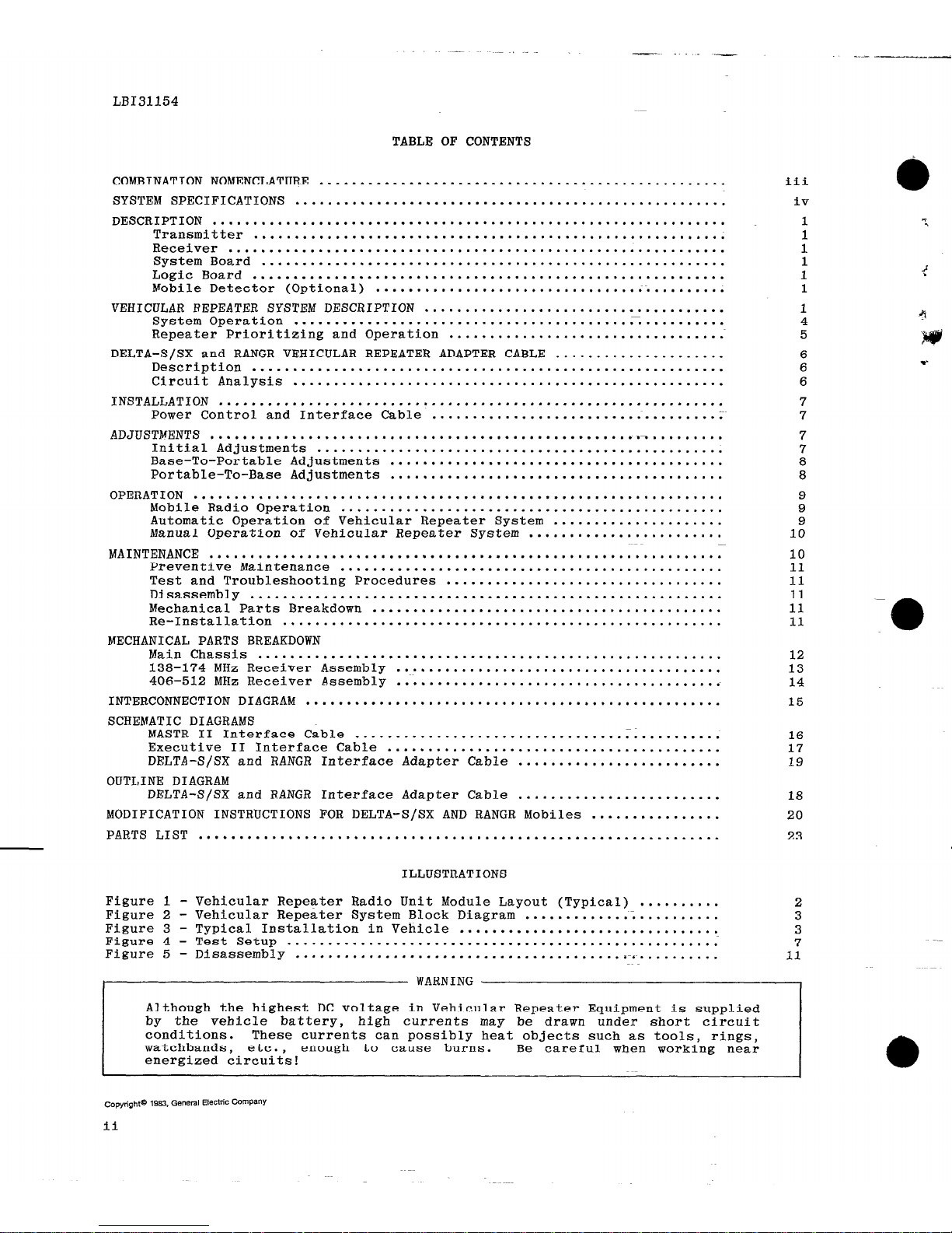
ILLUSTRATIONS
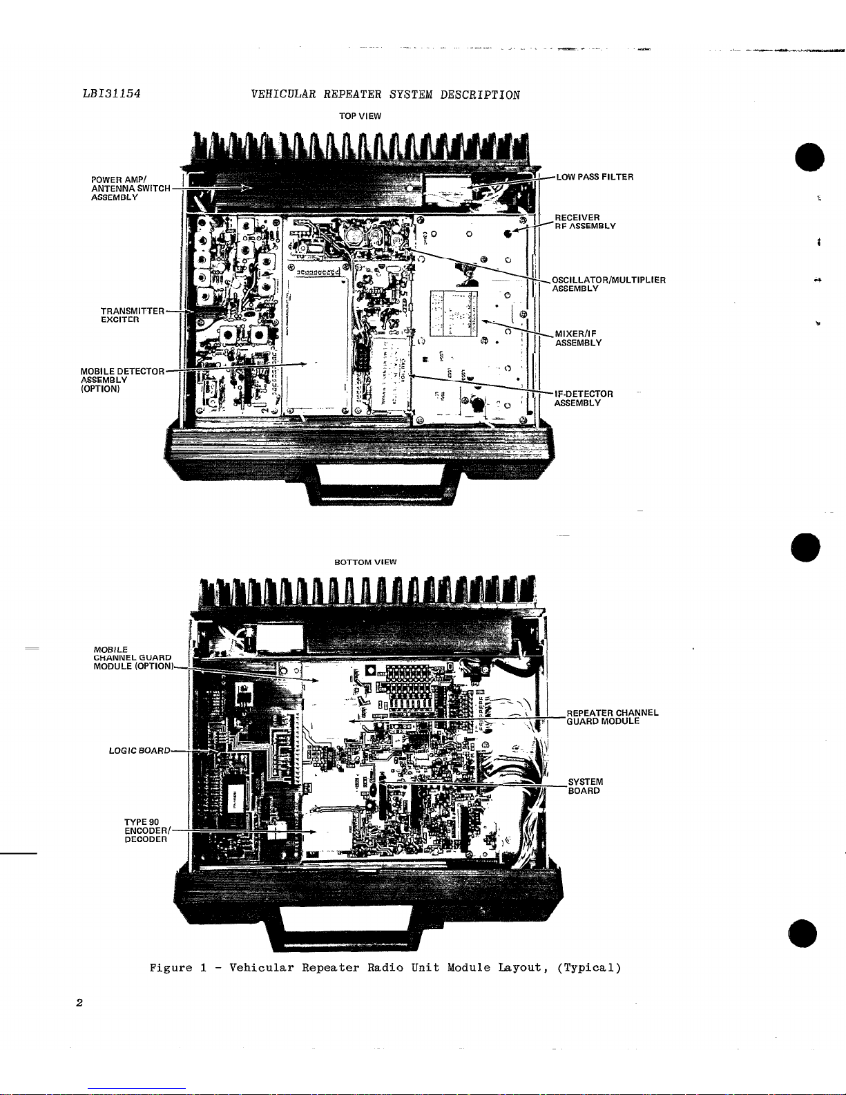
Figure 1 -
Vehicular Repeater Radio Unit Module Layout (Typical) ..........
2
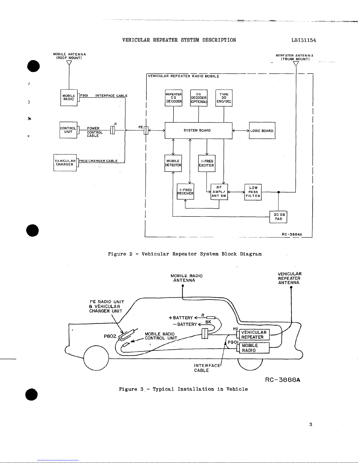
Figure 2 - Vehicular Repeater System Block Diagram
........................
3
Figure 3 - Typical Installation in Vehicle ................................
3
Figure 4 - Test Setup
.....................................................
7
Figure 5 - Disassembly
... ..*..................................-
. ...........
11
Although the highest DC voltage in Vehicular Repeater Equipment is supplied
by the vehicle battery,
conditions.
watchbands, etc.,
energized circuits!
enough to cauIruNls#._..-.,
high currents may be drawn under short circuit
These currents can possibly heat objects such as tools, rings,
c
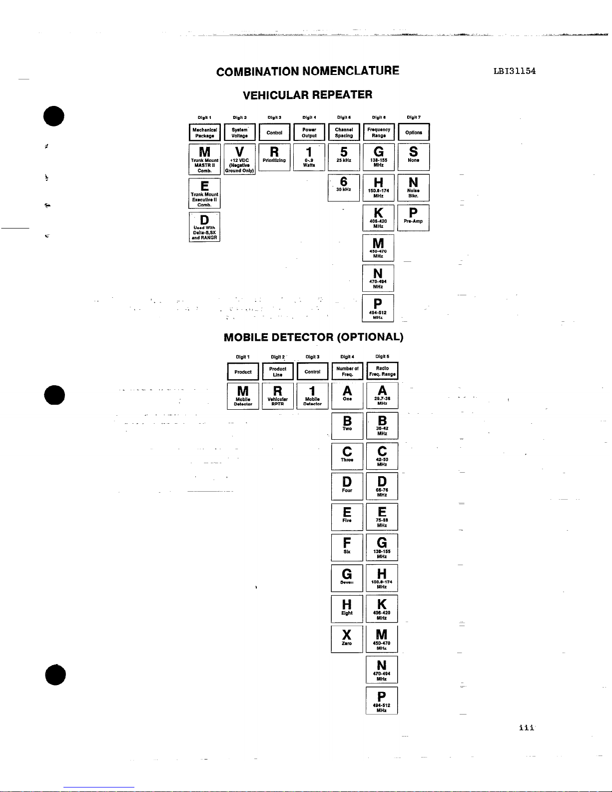
COMBINATION NOMENCLATURE
VEHICULAR REPEATER
MOBILE DETECTOR
B
I-l
Two
I
c
Thrm
L-J
!!2
MHZ
LB131154
iii

LB131154
" .
SYSTEMS SPECIFICATIONS*
FREQUENCY RANGE 138-174 MHz (KT-169-A)
406-512 MHz (KT-170-A)
INPUT VOLTAGE 13.8 VDC 220%
BATTERY DRAIN
Off
0.015 Amperes
Standby 0.450 Amperes
Repeat 0.850 Amperes
',
DIMENSIONS (H x W x D)
9.9 cml3.9 in.
‘x 34.3 cml13.5 in. x 34
cm/13.4 in.
3
WEIGHT
TEMPERATURE RANGE
9 kgs/20 lbs.
-3O='C! to +6O==C
(-22'F to +140"F)
DUTY CYCLE
Continuous
*
These specifications are intended primarily for the use of the serviceman.
Refer
to the appropriate Specifications Sheet in the applicable MAINTENANCE MANUAL for
specifications of standard units in the Vehicular Repeater System.
FCC FILING NUMBER
TRANSMITTER
KT-169-A
KT-170-A
POWER OUTPUT
300 Milliwatts
300 Milliwatts
FREQUENCY RANGE
0
138-174 MHz
406-420 MHz
450-512 MHz
iV
t
c
*
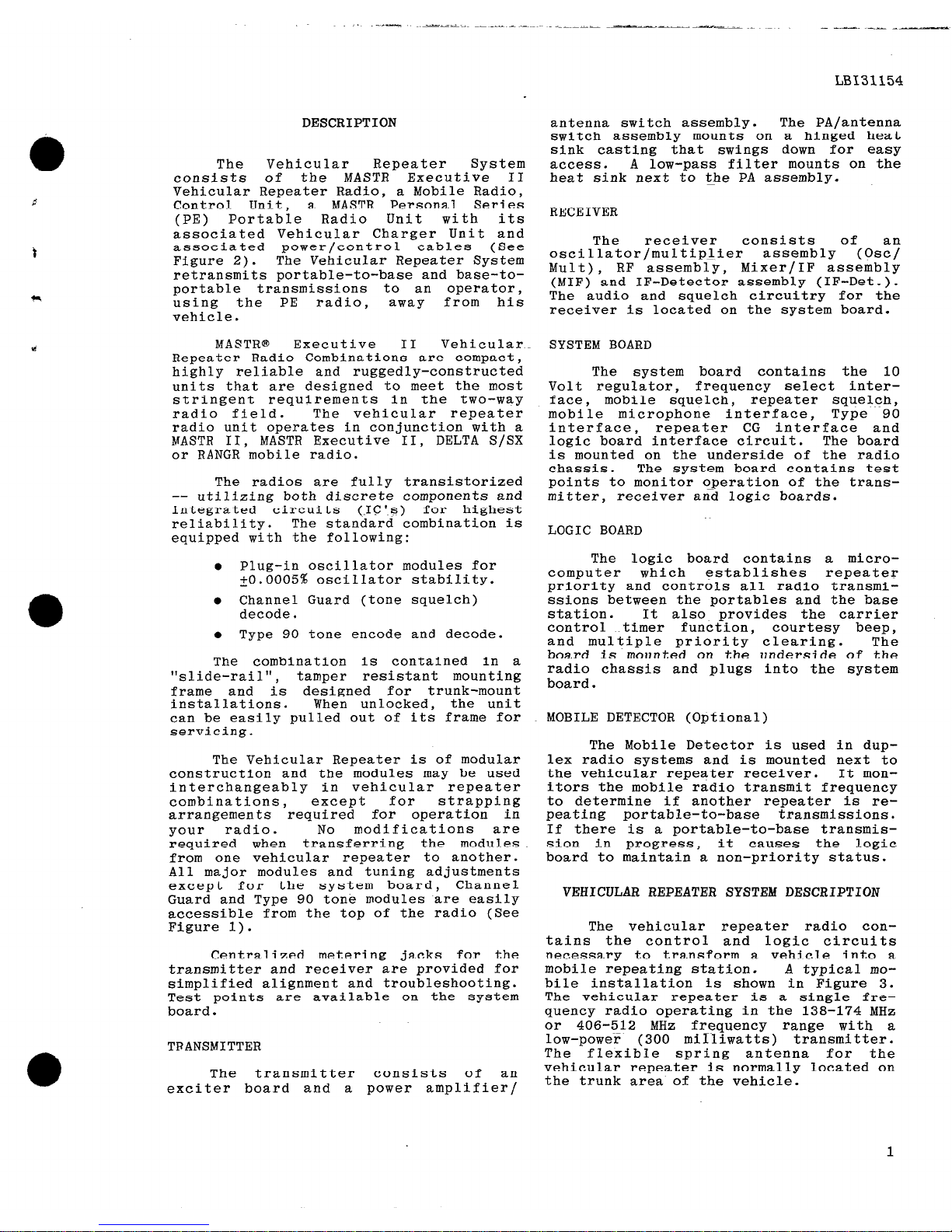
DESCRIPTION
The
Vehicular Repeater System
consists of the
MASTR Executive II
Vehicular Repeater Radio, a Mobile Radio,
Control Unit, a
MASTR Personal Series
(PE) Portable Radio Unit with its
associated Vehicular Charger Unit and
associated power/control
cables (See
Figure 2).
The Vehicular Repeater System
retransmits portable-to-base and base-toportable transmissions to an operator,
using the PE
radio,
away
from his
vehicle.
MASTRe Executive II Vehicular
Repeater Radio Combinations are compact,
highly reliable and ruggedly-constructed
units that are designed to meet the most
stringent requirements in the two-way
radio field.
The vehicular repeater
radio unit operates in conjunction with a
MASTR II,
MASTR Executive II, DELTA S/SE
or RANGR mobile radio.
The radios are fully transistorized
-- utilizing both discrete components and
integrated
circuits (.IC'~s) for highest
reliability.
The standard combination is
equipped with the following:
l
Plug-in oscillator modules for
tO.O005% oscillator stability.
e Channel Guard (tone squelch)
decode.
l
Type 90 tone encode and decode.
The combination is contained in a
"slide-rail",
tamper resistant mounting
frame and
is designed for trunk-mount
installations. When unlocked, the unit
can be easily pulled out of its frame for
servicing.
The Vehicular Repeater is of modular
construction and the modules may be used
interchangeably in vehicular repeater
combinations,
except for
strapping
arrangements
required for operation in
your
radio. No
modifications are
required when
transferring the modules
from one vehicular repeater to another.
All major modules and tuning adjustments
except for the system board, Channel
Guard and Type 90 tone modules are easily
accessible from the top of the radio (See
Figure 1).
Centralized metering jacks for the
transmitter and receiver are provided for
simplified alignment and troubleshooting.
Test points are available on the system
board.
TRANSMITTER
The transmitter
consists of an
exciter board and a power amplifier/
antenna switch assembly.
The PA/antenna
switch assembly mounts on a hinged heat
sink casting that swings down for easy
access.
A low-pass filter mounts on the
heat sink next to the PA assembly.
RECEIVER
The receiver consists of an
oscillator/multipIier assembly (Osc/
Mult),
RF assembly,
Mixer/IF assembly
(MIF) and IF-Detector assembly (IF-Det.).
The audio and squelch circuitry for the
receiver is located on the system board.
SYSTEM BOARD
The system board contains the 10
Volt regulator, frequency select inter-
face, mobile squelch, repeater squelch,
mobile microphone interface, Type 90
interface, repeater CG interface and
logic board interface circuit. The board
is mounted on the underside of the radio
chassis. The system board contains test
points to monitor operation of the transmitter, receiver and logic boards.
LOGIC BOARD
The logic board contains a micro-
computer
which
establishes
repeater
priority and controls all radio transmissions between the portables and the base
station.
It also provides the carrier
control timer function, courtesy beep,
and multiple priority clearing.
The
board is mounted on the underside of the
radio chassis and plugs into the system
board.
MOBILE DETECTOR (Optional)
The Mobile Detector is used in duplex radio systems and is mounted next to
the vehicular repeater receiver. It monitors the mobile radio transmit frequency
to determine if another repeater is re-
peating portable-to-base transmissions.
If there is a portable-to-base transmis-
sion in progress, it causes the logic
board to maintain a non-priority status.
VEHICULAR REPEATER SYSTEM DESCRIPTION
The vehicular repeater radio contains the control and logic circuits
necessary to transform a vehicle into a
mobile repeating station.
A typical mobile installation is shown in Figure 3.
The vehicular repeater is a single frequency radio operating in the 138-174 MHz
or 406-512 MHz frequency range with a
low-power (300 milliwatts) transmitter.
The flexible spring antenna for the
vehicular repeater is normally located on
the trunk area of the vehicle.
1
LB131154
-
._
--..-.
__. ~ . . a - -I
-
VEHICULAR REPEATER SYSTEM DESCRIPTION
TOP VIEW
.TER
/lULTlPLlER
BOTTOM VIEW
REPEATER CHANI
‘GUARD MODULE
UEL
Figure 1 - Veh .icular Repeater Rad io Unit Module Layout, (Typical
SYSTEM
‘BOARD
t
t
.+
MOBILE ANTENNA
(ROOF MOUNT)
VEHICULAR REPEATER SYSTEM DESCRIPTION
LB131154
REPEATER
(TRUN)c
=
VEHICULAR REPEATER RADIO MOBILE
I-------- --
_ _
REPEATER
-
1
I I I
P2 r7, P2
LA’
SYSTEM BOARD SYSTEM BOARD
4 c
> LOGIC BOARD > LOGIC BOARD
T T
I I
n
h
”
v _
MOBILE
I-FRED
DETECTOR
EXCITER
I--
RC -3BB4A
--
-i -
I
20 DB
PAD
0
J
Al
: Ml
v
JTENNA
OUNT)
Figure 2 - Vehicular Repeater System Block Diagram
MOBILE RADIO MOBILE RADIO
VEHICULAR VEHICULAR
ANTENNA ANTENNA
RAEYE RAEYE
PE RADIO UNIT PE RADIO UNIT
B VEHICULAR B VEHICULAR
CHARGER UNIT CHARGER UNIT
RC-3888A
Figure 3.-
Typical Installation in Vehicle
3

LB131154 VEHICULAR REPEATER SYSTEM DESCRIPTION
I NoTE I
The vehicular repeater should
not be used with gain antennas.
Also,
for improved operation,
the distance between the mobile
and repeater antennas should be
maximized.
When the Vehicular Repeater System
is enabled,
the mobile radio is used to
repeat transmissions to and from remate/
repeat base stations.
This arrangement
permits
cross-band repeat
operation to
minimize
interference
problems and
eliminate the requirements for duplexers.
The mobile radio control unit allows
the operator to select one of up to eight
operating channels for mobile-to-base
communications.
The vehicular charger contains the
control circuitry to apply power to the
vehicular repeater radio, to enable the
Vehicular Repeater System,
and to recharge the battery pack of the PE radio.
During normal mobile operation the PE
radio is inserted into the vehicular
charger
and
the REPEATER pushbutton
switch set to the "on" position.
This
places the Vehicular Repeater System in a
ready condition so that removal of the PE
radio unit automatically enables the
Vehicular Repeater System.
Power is automatically applied to
recharge the battery pack when the PE
radio is inserted into the charger.
The
amber LED indicator labeled CHARGE will
glow when positive contact has been made
and the green LED indicator labeled READY
will glow when the battery pack
is
fully
recharged.
The PE radio operates in the 138-
174 MHz or 406-512 MHz frequency range
with a medium power transmitter and using
a flexible spring antenna.
A channel
selector switch permits selection of up
to 8 channels.
Only one frequency channel is-,-used to communicate via the
vehicular repeater.
SYSTEM OPERATION
The
Vehicular ~Repeater
System
'extends the communications from a fixed
mobile
(vehicle)
system to a portable
communications
system permitting the
vehicle operator to remain in continuous
communication with the dispatch center or
other radio system units when away from
the vehicle.
There are three basic types
of operation possible when the operator
has left the vehicle with the PE radio.
One is portable-to-base operation which
uses the Vehicular Repeater System to
repeat any transmissions from the PE
radio to a remote/repeat base station for
communications with a dispatcher or to
other mobile radio units via a base
0
station repeater facility.
Another type of operation is the
base-to-portable wherein a dispatcher(s)
or other mobile radio units using a
remote/repeat base station can communicate with the PE 'radio operator through
the repeat function of the Vehicular
Repeater System.
The third type of operation involves
the PE radios for portable-to-portable
communications without activating the
repeater.
In portable-to-base operation the
Vehicular Repeater System is enabled.
When the PE radio user has the channel
select switch on the designated repeater'
channel and keys the unit, the transmitted signal is modulated with a Channel
Guard tone. When
this CG tone is
detected by the CG decoder in the Vehicular Repeater radio,
the microcomputer
on the logic board keys the mobile radio
transmitter.
The Vehicular Repeater system is
interrupted when the mobile microphone is
used. When the mobile PTT switch is
operated the repeat function is disabled
and the mobile radio is used for communications. When the mobile microphone use
0
is concluded,
the Vehicular Repeater
System will again be available for the
repeat function. However,
since repeater
priority is random as established by
software control,
an alternate repeater
system may assume priority status.
The base-to-portable operation is
the reverse of
the portable-to-base
operation described above.
During these two operations all PE
radios in the area will hear each other's
transmissions directly and the repeated
reply from the base station.
The thirdtype of op-eration involves
only the PE radio units and does not
require the repeating functions of the
Vehicular Repeater System.
A designated
channel not provided with the repeater CG
tone is used for direct portable-toportable communications. Since it does
not contain a CG tone, it cannot activate
the vehicular repeater.
However, all PE
radios in the area and on the designated
channel will hear the transmissions.
Returning the PE radio to the charg-
ing insert on-&e vehicular charger auto-
matically disables the Vehicular Repeater
System. Should the PE radio not be inserted into the vehicular
charger for
0
some reason (e.g., servicing, wearing of
4

-
_I__---
-._.-~
-e*.
.._
.i
=~..___L_d_
VEHICULAR REPEATER SYSTEM DESCRIPTION
LB131154
unit, etc.)
the REPEATER pushbutton
0
switch mustbe manually operated to the
"on" and "off" positions.
The microcomputer in each vehicular
repeater
utilizes a
random
counter to
establish priority.
The counter is
started each time a condition to repeat
is detected.
If no repeater begins to
repeat before the counter counts down the
repeater will begin to repeat and will
assume the priority state.
All other
The counter
repeaters will remain quiet.
consists of a fixed 400 millisecond delay
and a random count of 1.1 seconds.
Since
the value of the count is initialized
when the repeater is tuned on, each individual
repeater
will have a different
delay which will change each time the
repeater is powered up.-
A Carrier Control Timer (CCT) which
resides in microcomputer software,
prevents system tie-ups by timing base-toportable transmissions.
A DA jumper wire
Hl-H2 may be connected to disable the CCT
if desired.
Courtesy Beep
The Type 90 encoder is enabled for
approximately 30 milliseconds at the end
of each portable-to-base repeat transmission.
This tone burst or courtesy beep
lets the portable operator know that his
radio is working and his message has been
transmitted to base.
It may be desirable
to eliminate the courtesy beep in systems
using both the lQC331423 logic board and
the lQC328461 logic board.
Because of
the different method used to establish
repeater priority in vehicular repeaters
using logic board lQC328461 its possible
that the courtesy beep could cause all
repeaters so
equipped to count down
simultaneously the eight levels of priority.
This would allow all repeaters
equipped with the lQC328461 logic board
to temporality assume priority status.
For this reason a DA-jumper wire may be
connected between H5-H6 on the lQC331423
logic board to disable the courtesy beep.
Vehicular Repeater System Enable
When a vehicle containing the Vehi-
cular Repeater system equipment arrives
at a location that requires the operator
to be away from the vehicle and get maintain
communication,
the
Vehicular
Repeater
System can be
enabled.
Normally,
the PE radio is inserted in the
vehicular charger
and the
REPEATER
pushbutton
switch is in the
"on"
position.
The operator, when removing
the PE radio,
automatically enables the
Vehicular Repeater System.
The mobile
radio
will
operate on
the
channel
indicated by the control unit.
The PE
radio channel select switch should be set
to the
designated
repeat
channel
position.
When the PE radio is removed from
the vehicular charger unit, a switch
closure in the vehicular charger causes a
repeat enable signal to be applied to. the
logic circuitry in the vehicular repeater
radio. This, in turn, causes the vehicular repeater to transmit a 700 millisecond burst of Type 90 tone. Since no
other Vehicular Repeater Systems have
been enabled at this time the Type 90
tone burst has no effect. At the time of
the Type 90 tone burst, the microcomputer
established the repeater as the priority
repeater.
REPEATER PRIORITIZING AND OPERATION
The vehicuiar repeater contains a
prioritizing system to prevent more than
one radio from transmitting at once.
When a repeater is enabled,
it will
transmit a 700 millisecond Type 90 tone
on the portable frequency and goes into
the "priority state".
In priority, the
repeater will repeat as soon as a request
to repeat is heard.
A vehicular repeater
always listens ~for the Type 90 tone on
the portable frequency. If it hears the
tone, the repeater assumes that another
repeater has just been enabled and is
therefore the priority repeater.
All
repeaters who hear the tone will immediately jump to the "non-priority state".
A repeater in non-priority will not
repeat immediately.
It will listen for
another repeater to come up. If no other
repeater begins to repeat within a
specified time period,
the non-priority
repeater will assume that there is no
priority repeater present to repeat.
The
non-priority repeater
will
begin to
repeat and jump into the priority mode to
become the new priority repeater.
The
specified time period is random and will
vary from repeater to repeater.
The
random delay is between 400 ms and 1.1
seconds long.
(The random clock is
loaded with a different setting each time
a request to re_peat is heard.)
In a
system that is functioning correctly,
there can be any number of non-priority
repeaters,
but only one repeater will be
in priority,
and it will be the one doing
all of the repeating.
If the priority repeater leaves the
scene,
when the next request to repeat
comes along a ehort random time delay
will occur before one of the remaining
repeaters will step up to the priority
state and start to repeat. All of the
other repeaters will remain silent, and
stay in non-priority.
The microcomputer will recognize the
following conditions as repeat requirements.
 Loading...