

Page 1

GE 2LO*DV
Masoneilan* Products
ValVue* Software v2.8
(Rev &)
6RIWZDUH0anual
ValVue is a device management
software suite designed
exclusively for all
Masoneilan digital products.
ts.
1
Page 2

GE Oil & Gas
About this Guide
The information in this manual is subject to change without prior notice.
The information contained in this manual, in whole or part, shall not be transcribed or copied
without GE Oil and Gas’ written permission.
In no case does this manual guarantee the suitability of the positioner or the software or its
adaptability to a specific customer's needs.
Please report any errors or questions about the information in this manual to your local
supplier or visit www.ge-energy/valves.com.
Copyright
All software is the intellectual property of GE Oil & Gas. The complete design and manufacture
is the intellectual property of GE Oil & Gas. Masoneilan
trademarks of GE Oil & Gas. All information contained herein is believed to be accurate at the
time of publication and is subject to change without notice. All other trademarks and
copyrights are properties of their respective corporations.
ValVue Digital Communications Software Ver. 2.80
*
, FVP*, SVI, and ValVue are registered
Copyright 2014 by GE Oil & Gas. All rights reserved.
PN 055201-252 Rev. C
Document Changes
Version/Date Changes
B/6-2012 Added HART 6 functionality.
Updated screen captures throughout .
Added Burst section.
Updated ValVue Options screen for ValVue 2.8 functionality.
Reconfigured book to include sections for all ValVue components
as opposed to just SVI1000 and SVI II AP.
C/3-2014 Added SVI, SVI2, HDLT and 12400 to the book.
Changed description of how to physically configure digital
switches.
2
Page 3

Contents
Introduction .........................................................................................................................................................................................17
ValVue Lite and ValVue Trial ................................................................................................................................................17
Stand-Alone or Integrated ValVue.............................................................................................................................17
ValVue Tasks........................................................................................................................................................................18
About this Manual......................................................................................................................................................................18
ValVue Software Installation and Administration .............................................................................................................19
Requirements...............................................................................................................................................................................19
Hardware and Software Requirements..................................................................................................................19
Before Installing ValVue..........................................................................................................................................................19
HART Compliance..............................................................................................................................................................20
Failure to Communicate.................................................................................................................................................20
Installing ValVue.........................................................................................................................................................................21
Administration.............................................................................................................................................................................24
ValVue System Administration, Passwords, and Privilege Levels ...............................................................24
Starting Administration Program...............................................................................................................................25
Add Users ..............................................................................................................................................................................27
Editing User Accounts .....................................................................................................................................................28
Deleting a User Account.................................................................................................................................................28
Privilege Level......................................................................................................................................................................29
Starting ValVue ...........................................................................................................................................................................30
Registering ValVue ....................................................................................................................................................................30
Using Unregistered Software ...............................................................................................................................................37
Starting Unregistered Software..................................................................................................................................37
Offline Mode .................................................................................................................................................................................37
Offline Operation................................................................................................................................................................38
ValVue Setup ......................................................................................................................................................................................41
Overview ........................................................................................................................................................................................41
Configure the Set Options......................................................................................................................................................41
Configure Multiplexor Setup and Operation .................................................................................................................45
Mux Setup .............................................................................................................................................................................46
Mux Reset..............................................................................................................................................................................48
Troubleshooting ValVue Mux .......................................................................................................................................50
Configuring Burst Mode..........................................................................................................................................................51
Connecting Devices ........................................................................................................................................................................53
Connected Devices ...................................................................................................................................................................53
Selecting a Device .....................................................................................................................................................................54
Find by Tag ...........................................................................................................................................................................54
Re-Scan ..................................................................................................................................................................................54
Advanced Setup with ValVue .....................................................................................................................................................57
Methods to Set Up the SVI II AP...........................................................................................................................................57
3
Page 4

GE Oil & Gas
ValVue Digital Communications Software Ver. 2.80
Advanced Setup......................................................................................................................................................................... 57
Steps to Set Up SVI II AP................................................................................................................................................ 57
Configuration Parameters .................................................................................................................................................... 58
Calibration Steps ....................................................................................................................................................................... 58
Run Find Stops.................................................................................................................................................................... 58
Manual Find Stops............................................................................................................................................................ 59
Open Stop Adjustment ................................................................................................................................................... 61
Tri-Loop Configuration............................................................................................................................................................ 63
SVI II AP Software Manual ........................................................................................................................................................... 65
ValVue SVI II AP Work Environment ........................................................................................................................................ 67
Overview........................................................................................................................................................................................ 67
Working in ValVue..................................................................................................................................................................... 68
Toolbar ........................................................................................................................................................................................... 68
Tools Menu........................................................................................................................................................................... 68
Help Menu ............................................................................................................................................................................ 68
ValVue Help.................................................................................................................................................................................. 69
Exit.................................................................................................................................................................................................... 70
Change Mode.............................................................................................................................................................................. 70
Failsafe Mode...................................................................................................................................................................... 70
ValVue Screens........................................................................................................................................................................... 71
SVI II AP Monitor Screen ............................................................................................................................................................... 73
What You Can Do on the Monitor Screen...................................................................................................................... 73
Changing the Setpoint............................................................................................................................................................ 76
Entering Setpoint Value ................................................................................................................................................. 76
Status on the Monitor Screen.............................................................................................................................................. 77
Tag Information ......................................................................................................................................................................... 78
Changing Tag Information on the Monitor Screen ........................................................................................... 78
Send Command ......................................................................................................................................................................... 79
List of Available HART Commands............................................................................................................................ 80
Setup Wizard............................................................................................................................................................................... 82
Setup Wizard Selections ................................................................................................................................................ 83
Setting the Tag and Descriptor Data....................................................................................................................... 84
Setting the Air Action....................................................................................................................................................... 85
Calibrate Travel.................................................................................................................................................................. 85
Autotune................................................................................................................................................................................ 85
Setup Selections Made ................................................................................................................................................... 86
Progress Dialog.................................................................................................................................................................. 87
Monitor Context Menu ............................................................................................................................................................ 90
Restore SVI Data................................................................................................................................................................ 91
Reports................................................................................................................................................................................... 92
Configure Screen ............................................................................................................................................................................. 99
What You Can Do on the Configure Screen.................................................................................................................. 99
Tag Information .......................................................................................................................................................................100
4
Page 5

Characterization...................................................................................................................................................................... 102
Custom Characterization............................................................................................................................................ 103
Button Lock................................................................................................................................................................................107
Bumpless Transfer.................................................................................................................................................................. 107
Near Closed ............................................................................................................................................................................... 107
Position Limit Stops................................................................................................................................................................108
Single/Double Acting.............................................................................................................................................................108
Air-to-Open / Air-to-Close................................................................................................................................................... 108
Position Fault Limits...............................................................................................................................................................108
Language.................................................................................................................................................................................... 108
Pressure Units........................................................................................................................................................................... 109
Configure I/O.............................................................................................................................................................................109
Accessing Configure I/O..............................................................................................................................................109
Output Switches (DO)....................................................................................................................................................110
Digital Input (DI) ...............................................................................................................................................................111
Input Signal Range (AI) .................................................................................................................................................111
Position Retransmit (AO)..............................................................................................................................................111
Burst Settings............................................................................................................................................................................ 112
Configure Context Menu......................................................................................................................................................113
Custom Linearization.................................................................................................................................................... 114
Applying Configuration Changes..................................................................................................................................... 116
Trend Screen ................................................................................................................................................................................... 117
What you can do on the Trend Screen.........................................................................................................................117
Trend Graph Features........................................................................................................................................................... 118
Trend Context Menu .............................................................................................................................................................. 120
Calibrate Screen ............................................................................................................................................................................ 121
What you can do on the Calibrate Screen................................................................................................................. 121
Signal Calibration Procedure............................................................................................................................................. 122
Low Signal Value Calibration.....................................................................................................................................122
High signal Value Calibration....................................................................................................................................124
Pressure Calibration Procedure ....................................................................................................................................... 125
Advanced Parameters..........................................................................................................................................................127
Calibrate Context Menu.......................................................................................................................................................129
Reset to Factory Cal ...................................................................................................................................................... 130
Live Tuning.........................................................................................................................................................................131
Applying Calibration Screen Changes...........................................................................................................................131
Diagnostics Screen .......................................................................................................................................................................133
What you can do on the Diagnostics Screen ............................................................................................................ 133
Tag Information............................................................................................................................................................... 134
Continuous Diagnostics...............................................................................................................................................134
5
Page 6

GE Oil & Gas
ValVue Digital Communications Software Ver. 2.80
Diagnostic Tests.......................................................................................................................................................................134
Performing Diagnostic Tests......................................................................................................................................134
Standard Actuator Signature (Std. Actuator Sig.).............................................................................................137
Step Test..............................................................................................................................................................................142
Ramp Test...........................................................................................................................................................................144
Extended Actuator Signature (Extended Act. Sig.)...........................................................................................146
Diagnostics Context Menu..................................................................................................................................................147
Reset Continuous Diagnostics..................................................................................................................................148
Status Screen ..................................................................................................................................................................................149
What you can do on the SVI II AP Status Screen......................................................................................................149
Clear Current Faults.......................................................................................................................................................150
Clear All Faults..................................................................................................................................................................150
Status Code List ...............................................................................................................................................................150
Status Context Menu.....................................................................................................................................................161
Check Screen- Advanced Troubleshooting .......................................................................................................................163
What you can do on the Check Screen ........................................................................................................................163
Information Displayed ..........................................................................................................................................................164
Check Context Menu..............................................................................................................................................................164
Set I/P............................................................................................................................................................................................165
Changing HART Versions ...........................................................................................................................................................167
Changing SVI II AP to HART 6.............................................................................................................................................167
References ........................................................................................................................................................................................169
Overview......................................................................................................................................................................................169
Supported HART Modems ...................................................................................................................................................169
SVi1000 Software Manual .........................................................................................................................................................185
Introduction .....................................................................................................................................................................................187
About This Manual..................................................................................................................................................................187
Conventions Used in This Manual...........................................................................................................................187
ValVue Overview......................................................................................................................................................................188
System Requirements...........................................................................................................................................................188
Hardware............................................................................................................................................................................188
Software..............................................................................................................................................................................188
ValVue SVi1000 Work Environment ......................................................................................................................................189
Overview......................................................................................................................................................................................189
Working in SVi1000 ................................................................................................................................................................190
Toolbar.................................................................................................................................................................................190
Modes of Operation .......................................................................................................................................................190
Change Mode....................................................................................................................................................................190
Exit..........................................................................................................................................................................................190
SVi1000 Help ...................................................................................................................
He
lp Menu ..........................................................................................................................................................................191
..........................................................191
6
Page 7

SVi1000 Tabs.............................................................................................................................................................................192
Monitor Tab ....................................................................................................................................................................... 192
Trend Tab............................................................................................................................................................................193
Configure Tab................................................................................................................................................................... 194
Status Tab ..........................................................................................................................................................................196
Check....................................................................................................................................................................................197
Monitor ............................................................................................................................................................................................... 199
What You Can Do on the Monitor Tab .......................................................................................................................... 199
Adjust Operations ................................................................................................................................................................... 200
1. Tag Information.......................................................................................................................................................... 200
2. Signal/Position Data.................................................................................................................................................201
3. Status on the Monitor Tab.....................................................................................................................................202
4. Information Pane.......................................................................................................................................................204
Monitor Context Menu..........................................................................................................................................................205
Reports......................................................................................................................................................................................... 207
How to Create Reports.................................................................................................................................................207
Creating Report Template Files................................................................................................................................207
Report Setup ..................................................................................................................................................................... 211
Generate Report..............................................................................................................................................................212
Setup Wizard............................................................................................................................................................................. 213
Setup Wizard Selections.............................................................................................................................................. 214
Trend ................................................................................................................................................................................................... 225
What you can do on the Trend Tab................................................................................................................................ 225
Trend Graph Features...........................................................................................................................................................226
Changing the Graph View........................................................................................................................................... 226
Capture to Clipboard.....................................................................................................................................................226
Trend Context Menu...................................................................................................................................................... 227
Configure .......................................................................................................................................................................................... 229
What You Can Do on the Configure Tab......................................................................................................................229
Tag Information.......................................................................................................................................................................230
Position Fault Limits...............................................................................................................................................................231
Characterization...................................................................................................................................................................... 232
Custom Characterization............................................................................................................................................ 233
Custom Linearization....................................................................................................................................................234
Air Action.....................................................................................................................................................................................235
Bumpless Transfer.................................................................................................................................................................. 236
Position Limits........................................................................................................................................................................... 236
DO Output Switches...............................................................................................................................................................237
Configuring Output Switches ....................................................................................................................................237
Configure Context Menu......................................................................................................................................................239
Calibrate ............................................................................................................................................................................................241
What you can do on the Calibrate Tab......................................................................................................................... 241
Calibration..................................................................................................................................................................................243
7
Page 8

GE Oil & Gas
ValVue Digital Communications Software Ver. 2.80
PID and Advanced Parameters ........................................................................................................................................244
Advanced Parameters..................................................................................................................................................245
Open Stop Adjustment..........................................................................................................................................................246
Calibrate Context Menu .......................................................................................................................................................247
Run Find Stops..................................................................................................................................................................248
Manual Find Stops..........................................................................................................................................................250
Auto Tune............................................................................................................................................................................251
Status ..................................................................................................................................................................................................253
What you can do on the Status Tab...............................................................................................................................253
Active Faults ..............................................................................................................................................................................254
General.........................................................................................................................................................................................255
Instrumentation .......................................................................................................................................................................256
Actuator.......................................................................................................................................................................................257
Pneumatics ................................................................................................................................................................................258
Critical...........................................................................................................................................................................................259
Electronics ..................................................................................................................................................................................260
Clear Current Faults ...............................................................................................................................................................261
Clear All Faults ..........................................................................................................................................................................262
Fault Matrix ................................................................................................................................................................................263
Status Context Menu .............................................................................................................................................................272
Check ..................................................................................................................................................................................................273
What you can do on the Check Tab ...............................................................................................................................273
Information Displayed on the Check Tab ....................................................................................................................274
Check Context Menu..............................................................................................................................................................275
Optional Switch Load Limits .....................................................................................................................................................277
Output Switches.......................................................................................................................................................................277
Introduction.......................................................................................................................................................................277
Checking Switch Operation................................................................................................................................................279
ValVue Commands.........................................................................................................................................................279
ValVue 12400 Software ..............................................................................................................................................................281
ValVue 12400 Work Environment .........................................................................................................................................283
What is ValVue 12400?.........................................................................................................................................................283
Welcome to ValVue 12400 .........................................................................................................................................283
ValVue 12400's Work Environment ........................................................................................................................284
Working in ValVue 12400............................................................................................................................................285
Toolbar
.................................................................................................................................................................................285
Tools Menu.........................................................................................................................................................................286
Modes of Operation .......................................................................................................................................................287
Change Mode....................................................................................................................................................................288
Exit..........................................................................................................................................................................................291
Help .......................................................................................................................................................................................291
8
Page 9

ValVue 12400 Help................................................................................................................................................................. 291
Types of Help Available................................................................................................................................................ 291
Toolbar Help......................................................................................................................................................................291
Context Sensitive Help ................................................................................................................................................. 292
ValVue 12400 Screens..........................................................................................................................................................292
12400 Monitor.................................................................................................................................................................. 292
Trend..................................................................................................................................................................................... 293
Basic Setup ........................................................................................................................................................................ 295
Advanced Setup .............................................................................................................................................................. 296
Transmitter Diagnostics ..............................................................................................................................................297
Status ................................................................................................................................................................................... 298
Check....................................................................................................................................................................................299
Controller Monitor .......................................................................................................................................................... 300
What you can do on the 12400 Controller Setup Screen ............................................................................301
Controller Monitor ......................................................................................................................................................................... 303
What you can do with the 12400 Controller Monitor Screen ............................................................................303
Tag .................................................................................................................................................................................................304
Controller Monitor Controller Bargraphs .....................................................................................................................304
Controller Output............................................................................................................................................................305
Level Measurement .......................................................................................................................................................306
Send Command.......................................................................................................................................................................307
PID Controller Mode............................................................................................................................................................... 309
12400 Monitor Context Menu ........................................................................................................................................... 310
12400 Monitor Context Menu................................................................................................................................... 310
Reset..................................................................................................................................................................................... 311
Restore 12400 Data.......................................................................................................................................................312
Save 12400 Data ............................................................................................................................................................313
Reports ................................................................................................................................................................................ 314
12400 Monitor ................................................................................................................................................................................323
What
you can do on the 12400 Monitor Screen ...................................................................................................... 323
Level Indicator..........................................................................................................................................................................324
Status on the 12400 Monitor Screen............................................................................................................................. 324
Changing Tag and Descriptor Information on the 12400 Monitor Screen ..................................................325
Changing Message on 12400 Monitor Screen..........................................................................................................328
Send Command.......................................................................................................................................................................330
Send Command...............................................................................................................................................................330
Command Selection ......................................................................................................................................................332
Command Result Display............................................................................................................................................ 334
Update Configured Data ..................................................................................................................................................... 334
Controller Setup .............................................................................................................................................................................335
What you can do on the 12400 Controller Setup Screen ....................................................................................335
PID Controller Alarms............................................................................................................................................................336
PID Parameters Settings...................................................................................................................................................... 337
PID Controller Configuration..............................................................................................................................................338
PID Controller Setpoint Range ..........................................................................................................................................339
9
Page 10

GE Oil & Gas
ValVue Digital Communications Software Ver. 2.80
Trend ...................................................................................................................................................................................................341
What you can do on the Trend Screen .........................................................................................................................341
Trend Screen with Controller Activation ..............................................................................................................342
Graph Display............................................................................................................................................................................344
Changing the Graph View...................................................................................................................................................345
Trend Context Menu ..............................................................................................................................................................346
Detach Trend.............................................................................................................................................................................347
Capture to Clipboard .............................................................................................................................................................347
Basic Setup .......................................................................................................................................................................................349
What you can do on the Basic Setup Screen.............................................................................................................349
Apply .....................................................................................................................................................................................350
Exiting in Setup Mode....................................................................................................................................................350
Changing Tag Information on the Basic Setup Screen .........................................................................................351
Transmitter.................................................................................................................................................................................353
Transmitter Mode ...........................................................................................................................................................353
Transmitter Mounting ...................................................................................................................................................354
Transmitter Action..........................................................................................................................................................355
Display Language...........................................................................................................................................................356
Level Transmitter.....................................................................................................................................................................357
Level Transmitter ............................................................................................................................................................357
Record SG ...........................................................................................................................................................................357
Zero........................................................................................................................................................................................358
Span ......................................................................................................................................................................................359
Applying Basic Setup Changes .........................................................................................................................................361
Basic Setup Context Menu..................................................................................................................................................362
SG Service...................................................................................................................................................................................363
Signal Range..............................................................................................................................................................................365
Advanced Setup .............................................................................................................................................................................367
What you can do on the Advanced Setup Screen...................................................................................................367
Local User Interface...............................................................................................................................................................368
Changing Configuration ..............................................................................................................................................369
SG Meter Calibration..............................................................................................................................................................370
SG Meter Calibration Zero...........................................................................................................................................370
Span ......................................................................................................................................................................................371
Reset to Factory...............................................................................................................................................................372
Set SIL2 Settings ......................................................................................................................................................................373
Alarm.............................................................................................................................................................................................374
Alarm Hysteresis .............................................................................................................................................................375
Range............................................................................................................................................................................................376
Change Level LRV or URV Setting............................................................................................................................376
Changing Level Units ....................................................................................................................................................377
Zero Shift.............................................................................................................................................................................378
Reduced Span ..................................................................................................................................................................378
10
Page 11

DO Switches .............................................................................................................................................................................. 379
DO Switches ...................................................................................................................................................................... 379
Configuring DO Switches ............................................................................................................................................380
Database.....................................................................................................................................................................................382
Database ............................................................................................................................................................................ 382
Displacer.............................................................................................................................................................................382
Displacer Type.................................................................................................................................................................. 386
Torque Tube and Chamber........................................................................................................................................ 387
Chamber Options............................................................................................................................................................ 392
Options ................................................................................................................................................................................ 393
Applying Database Changes.....................................................................................................................................394
Filters and Tuning ...................................................................................................................................................................395
Filters and Tuning...........................................................................................................................................................395
Smart Filter Enable.........................................................................................................................................................396
Filter Parameters ............................................................................................................................................................397
Autotune ............................................................................................................................................................................. 400
Damping .............................................................................................................................................................................401
Applying Filters and Tuning Changes....................................................................................................................401
Calibration Filter..............................................................................................................................................................401
Calibration Tools...................................................................................................................................................................... 403
Calibration Tools ............................................................................................................................................................. 403
Signal Selection ............................................................................................................................................................... 404
4 - 20 mA Calibration....................................................................................................................................................405
Coupling.............................................................................................................................................................................. 410
Calibration Reset............................................................................................................................................................. 411
Advanced Setup Context Menu........................................................................................................................................415
Applying Advanced Setup Changes...............................................................................................................................416
Transmitter Diagnostics ............................................................................................................................................................. 417
What you can do on the Transmitter Diagnostics Screen...................................................................................417
Continuous Diagnostic Data..............................................................................................................................................418
Reset Data..........................................................................................................................................................................418
Detail.....................................................................................................................................................................................419
Service Time ..............................................................................................................................................................................420
Reset..................................................................................................................................................................................... 420
Set Interval.........................................................................................................................................................................421
AO1/AO0/Signal Trim in Raw Count...............................................................................................................................422
Calibration Raw Range.........................................................................................................................................................423
Specific Gravity Meter...........................................................................................................................................................424
Transmitter Diagnostics Context Menu........................................................................................................................426
Status .................................................................................................................................................................................................. 427
What you can do on the Status Screen........................................................................................................................427
Active Faults .............................................................................................................................................................................. 428
Log Only.......................................................................................................................................................................................429
Annunciate.................................................................................................................................................................................430
User Faults 2..............................................................................................................................................................................431
11
Page 12

GE Oil & Gas
ValVue Digital Communications Software Ver. 2.80
Failsafe.........................................................................................................................................................................................432
User Faults 1..............................................................................................................................................................................433
Clearing Faults..........................................................................................................................................................................434
Clearing Individual Fault..............................................................................................................................................434
Clear Current Faults.......................................................................................................................................................436
Clear All Faults..................................................................................................................................................................437
Set Fail High/Fail Low............................................................................................................................................................438
Status Context Menu .............................................................................................................................................................440
Check ..................................................................................................................................................................................................441
What you can do on the Check Screen ........................................................................................................................441
Check Context Menu..............................................................................................................................................................442
ValVue VECTOR Software ..........................................................................................................................................................443
Introduction .....................................................................................................................................................................................445
Introduction ...............................................................................................................................................................................445
ValVue VECTOR Software ....................................................................................................................................................446
About This Manual..................................................................................................................................................................446
Conventions Used in This Manual...........................................................................................................................446
Installation ........................................................................................................................................................................................447
Installation..................................................................................................................................................................................447
Requirements....................................................................................................................................................................447
HART Related Issues ......................................................................................................................................................447
ValVue VECTOR Operational Overview ...............................................................................................................................449
Operational Overview ...........................................................................................................................................................449
Overview Tab Tools Menu and Context Menu...................................................................................................451
Working in ValVue VECTOR.................................................................................................................................................456
Toolbar.................................................................................................................................................................................456
Modes of Operation .......................................................................................................................................................456
Exit..........................................................................................................................................................................................456
ValVue VECTOR Help..............................................................................................................................................................456
Help Menu ..........................................................................................................................................................................456
ValVue VECTOR Tabs .............................................................................................................................................................457
Overview Tab ....................................................................................................................................................................457
Trend Tab............................................................................................................................................................................458
Configure Tab ...................................................................................................................................................................459
Status Tab...........................................................................................................................................................................461
Communication Tab ......................................................................................................................................................462
Alerts Tab............................................................................................................................................................................463
Battery Tab.........................................................................................................................................................................464
Setup Wizard ...................................................................................................................................................................................465
Setup Wizard Screen .............................................................................................................................................................465
Run Setup Wizard ...........................................................................................................................................................467
Scan for Devices..............................................................................................................................................................468
12
Page 13

Trend ................................................................................................................................................................................................... 469
Trend Tab....................................................................................................................................................................................469
Trend Graph Features...........................................................................................................................................................470
Changing the Graph View........................................................................................................................................... 470
Capture to Clipboard.....................................................................................................................................................470
Trend Right Click and Context Menu.............................................................................................................................. 471
Configure .......................................................................................................................................................................................... 473
Configure Screen: Overview...............................................................................................................................................473
Configure Power Tab.............................................................................................................................................................474
Configure Wireless Tab ........................................................................................................................................................ 477
Configure Wired Tab..............................................................................................................................................................479
Configure 4-20 mA Tab........................................................................................................................................................481
Create a PV Linearization Table...............................................................................................................................483
Configure Burst Settings Tab.............................................................................................................................................484
Configure Auto Burst.....................................................................................................................................................489
Configure Manual Burst...............................................................................................................................................489
Configure Event Notification Tab..................................................................................................................................... 490
Configure Adapter Info Tab................................................................................................................................................ 495
Configure Time Screen ......................................................................................................................................................... 498
Configure Tab Tools and Context Menu.......................................................................................................................499
Maintenance ...................................................................................................................................................................................501
Maintenance Tab .................................................................................................................................................................... 501
Maintenance Tab Tools and Context Menu................................................................................................................502
Status .................................................................................................................................................................................................. 505
Status Screen: General.........................................................................................................................................................505
Active Faults......................................................................................................................................................................506
Device_Status................................................................................................................................................................... 507
IO_and_Subdevice_Status .........................................................................................................................................508
Ext_Device_Status..........................................................................................................................................................509
WirelessHART_Status....................................................................................................................................................510
Device_Diagnostic_Status_0 ....................................................................................................................................511
Device_Specific_Status_0 ..........................................................................................................................................512
Device_Specific_Status_1 ..........................................................................................................................................513
Communication ............................................................................................................................................................................. 515
Communication Tab .............................................................................................................................................................. 515
Communication Tab Tools and Context Menu.......................................................................................................... 518
Alerts ................................................................................................................................................................................................... 519
Alerts Tab.................................................................................................................................................................................... 519
Alerts Tab Tools and Context Menu................................................................................................................................520
Battery ................................................................................................................................................................................................ 521
Battery Info Screen ................................................................................................................................................................ 521
Battery Tab Tools and Context Menu............................................................................................................................ 523
13
Page 14

GE Oil & Gas
ValVue Digital Communications Software Ver. 2.80
ValVue HDLT Software ................................................................................................................................................................525
Monitor Tab................................................................................................................................................................................527
Tag Information...............................................................................................................................................................527
Status....................................................................................................................................................................................528
Change Mode....................................................................................................................................................................532
Report...................................................................................................................................................................................533
Menu - Monitor.................................................................................................................................................................534
Trend Tab ....................................................................................................................................................................................535
Trend Graph.......................................................................................................................................................................535
Menu - Trend.....................................................................................................................................................................536
Configuration Tab ...................................................................................................................................................................536
Menu - Configure ............................................................................................................................................................539
Calibration Tab .........................................................................................................................................................................540
Level Transmitter Calibration....................................................................................................................................541
Interface Transmitter Calibration............................................................................................................................541
Specific Gravity Meter Calibration...........................................................................................................................541
Menu - Calibrate..............................................................................................................................................................541
Calibration Parameters Tab ...............................................................................................................................................542
Menu - Calibrate..............................................................................................................................................................543
Calibration Tools Tab.............................................................................................................................................................544
4-20 mA Calibration .....................................................................................................................................................544
Coupling ..............................................................................................................................................................................545
Menu - Calibrate..............................................................................................................................................................545
Controller Parameters Tab..................................................................................................................................................546
Menu - Controller ............................................................................................................................................................548
Controller Tab ...........................................................................................................................................................................549
Menu - Controller ............................................................................................................................................................550
Configuration DataBase Tab .............................................................................................................................................551
Menu - Configure ............................................................................................................................................................552
Transmitter Diagnostics Tab..............................................................................................................................................553
Smart Filtering Coefficients........................................................................................................................................553
Menu - Diagnostics ........................................................................................................................................................554
Menu Bar and Footer Buttons...........................................................................................................................................555
ValVue SVI Software ....................................................................................................................................................................557
Monitor Tab................................................................................................................................................................................559
Mode .....................................................................................................................................................................................563
Command Result Display............................................................................................................................................564
Read Status........................................................................................................................................................................567
Menu - Monitor.................................................................................................................................................................567
Trend Tab ....................................................................................................................................................................................568
Menu- Trend......................................................................................................................................................................570
Configure Tab............................................................................................................................................................................571
Custom Characterization ............................................................................................................................................575
Custom Linearization ....................................................................................................................................................576
Menu -Configure .............................................................................................................................................................577
14
Page 15

Controller Configure Tab .....................................................................................................................................................578
Menu -Controller Configuration...............................................................................................................................580
Calibrate Tab.............................................................................................................................................................................581
Calibration Value.............................................................................................................................................................583
Calibration Value- 2nd input Signal .......................................................................................................................583
Calibration Value- Pressure .......................................................................................................................................584
Open Stop Adjustment.................................................................................................................................................584
Pressure Calibration Procedure...............................................................................................................................584
Signal Calibration Procedure..................................................................................................................................... 585
Auxiliary Signal Calibration Procedure .................................................................................................................586
Find Stops........................................................................................................................................................................... 586
Manual Find Stops.......................................................................................................................................................... 588
Menu - Calibrate..............................................................................................................................................................588
Diagnostics Tab .......................................................................................................................................................................589
Diagnostic Reports......................................................................................................................................................... 595
Menu - Diagnostics........................................................................................................................................................600
Status Tab...................................................................................................................................................................................601
Menu -Status Tab ...........................................................................................................................................................603
Check Tab...................................................................................................................................................................................604
Set I/P ...................................................................................................................................................................................605
Menu-Check......................................................................................................................................................................605
Controller Tab ........................................................................................................................................................................... 606
Menu - Controller............................................................................................................................................................ 608
Controller Settings Tab.........................................................................................................................................................609
Menu Bar and Footer Buttons...........................................................................................................................................612
ValVue SVI Software ....................................................................................................................................................................613
Monitor Tab................................................................................................................................................................................ 615
Mode.....................................................................................................................................................................................618
Command Result Display............................................................................................................................................619
Setup Wizard.....................................................................................................................................................................620
Read Status .......................................................................................................................................................................623
Menu - Monitor ................................................................................................................................................................623
Trend Tab....................................................................................................................................................................................624
Menu - Trend.....................................................................................................................................................................626
Configure Tab ...........................................................................................................................................................................626
Custom Characterization............................................................................................................................................ 630
Custom Linearization.................................................................................................................................................... 632
Menu - Configure............................................................................................................................................................633
Calibrate Tab.............................................................................................................................................................................634
Menu - Calibrate..............................................................................................................................................................638
Diagnostics Tab .......................................................................................................................................................................639
Diagnostic Reports.........................................................................................................................................................646
Menu - Diagnostics........................................................................................................................................................ 651
Status Tab................................................................................................................................................................................... 652
Menu - Status ...................................................................................................................................................................653
15
Page 16

GE Oil & Gas
ValVue Digital Communications Software Ver. 2.80
Check Tab ...................................................................................................................................................................................654
Menu - Check....................................................................................................................................................................656
Menu Bar and Footer Buttons...........................................................................................................................................657
16
Page 17

Introduction
The ValVue software package provides a powerful interface to Masoneilan Smart Valve
Interfaces, the 12400 Digital Level Transmitter (HDLT), and other HART instruments. This manual
describes the functionality of ValVue software and contains information needed to install and
use ValVue with the SVI II AP, SVi1000, DLT 12400 positioners and the VECTOR WirelessHART
adapter.
ValVue Lite and ValVue Trial
ValVue has a 60-day free trial period before a license is required. After the 60-day trial period,
ValVue will not execute. The trial period allows you to evaluate advanced functions such as:
Diagnostic Procedures
Report Generation
1
Password Administration
ValVue Lite is offered without registration. It provides sufficient functions to fully commission,
configure, and start up a positioner on a control valve.
Stand-Alone or Integrated ValVue
ValVue can be accessed as a standalone application or it can be accessed as a SNAP-ON to the
Emerson Process Management AMS, or a Plug In Application to Yokogawa system. Procedures
for finding and selecting devices are different in the two contexts. ValVue standalone offers
login, user administration, and device selection. For AMS SNAP-ON users, the AMS login, user
administration, and device selection, methods are used. The SNAP-ON application requires a
license. Contact the factory for licensing information.
17
Page 18

GE Oil & Gas
ValVue Tasks
The SVI II AP and SVi1000 can be configured, calibrated, and operated locally or remotely
using ValVue software on a Windows based computer with a HART modem. Normal control
signaling is with 4 to 20 mA DC current (ANSI/ISA-50.1-1982 - (R1992)). For more information
on the individual devices, refer to SVI II AP Instruction Manual (GEA19681) or the SVi1000
Instruction Manual (GEA19363), Model V1100 Wireless Adapter Instruction Manual (GEA19362)
or 12400 Series Level Transmitter Instruction Manual an Safety Guide (GEA19367).
By using ValVue software it is possible to monitor, configure, calibrate, control and perform
valve diagnostics, remotely. ValVue can also provide a basic interface to other HART
instruments.
About this Manual
This manual is intended to assist you in easily installing, administrating, and using ValVue to
set up, configure, calibrate, monitor operation, and troubleshoot the ValVue family of
positioners. This manual contains subsections for each device.
ValVue Digital Communications Software Ver. 2.80
18
Page 19

ValVue Software Installation and
NOTE
Administration
Requirements
Using the ValVue installation procedures detailed in this chapter requires basic knowledge of
Microsoft Windows operating systems and Masoneilan positioners.
For installation and administration of AMS, see instructions provided with AMS.
Hardware and Software Requirements
ValVue is distributed on a CD-ROM and runs on a standard IBM-compatible computer. To
successfully install and run ValVue, your computer system must meet or exceed the following
minimum hardware and software requirements.
2
Windows XP SP2, Window Server 2003 SP1 or Window Server 2003 R2, Windows Server
2008, or Windows 7
Windows Pentium or compatible microprocessor; 64 Mb RAM
CD-ROM or DVD-ROM drive
An available serial communication port or USB port
A HART modem
RS232/485 converter for HART Multiplexor
500 MB of free hard disk space to install and run ValVue
Before Installing ValVue
Before installing ValVue, determine which port the computer uses for serial (RS-232 or USB)
communication. The HART modem and RS232/485 or USB converter for ValVue multiplexor
configuration both use this port for communication with the positioner.
19
Page 20

GE Oil & Gas
HART Compliance
The positioner requires a HART compliant communications loop. The HART protocol specifies
the noise level, impedance requirements, and configuration of the loop. Conventional
communications loops consisting of the following components meet requirements for HART
compliance.
Quality current source having low noise and high impedance
Minimum loop impedance of 250 Ohms
Twisted pair cable suitable for 4 - 20 mA current loops
When a safe barrier separates the communicating devices, a HART compliant barrier must be
used.
ValVue Digital Communications Software Ver. 2.80
NOTE You cannot connect or use ValVue and another HART master
terminal device (at the same time), for example a handheld device.
CAUTION Some Distributed Control System output circuits are incompatible
Failure to Communicate
If the PC (using a modem) fails to communicate with the HART positioner the message No
Devices Found appears in the Connected Devices page. The message HART I/O Failed appears
if the device communications fails during the session. Communication failure prevents the PC
from establishing a link. Possible causes of communications failure related to installation
include:
Insufficient Loop Current and Voltage
Poor wiring contacts
Improper connection of the HART modem to the computer
Incorrect serial port
Using ValVue with another HART master terminal in service
Insufficient loop impedance (a minimum of 250 Ohms is required
with the HART protocol. Connecting a HART modem to such a
circuit can cause a process upset. A HART filter can be used.
Consult the DCS manufacturer to verity that the DCS is compatible
with HART, before connecting a HART modem and using ValVue.
Field device has a non-zero polling address (Set ValVue to multidrop)
If HART compliance problems are suspected prepare a detailed description of the loop,
including all devices on the loop, type of wiring used, loop length, and presence of any possible
interference sources before contacting the factory for assistance.
20
Page 21
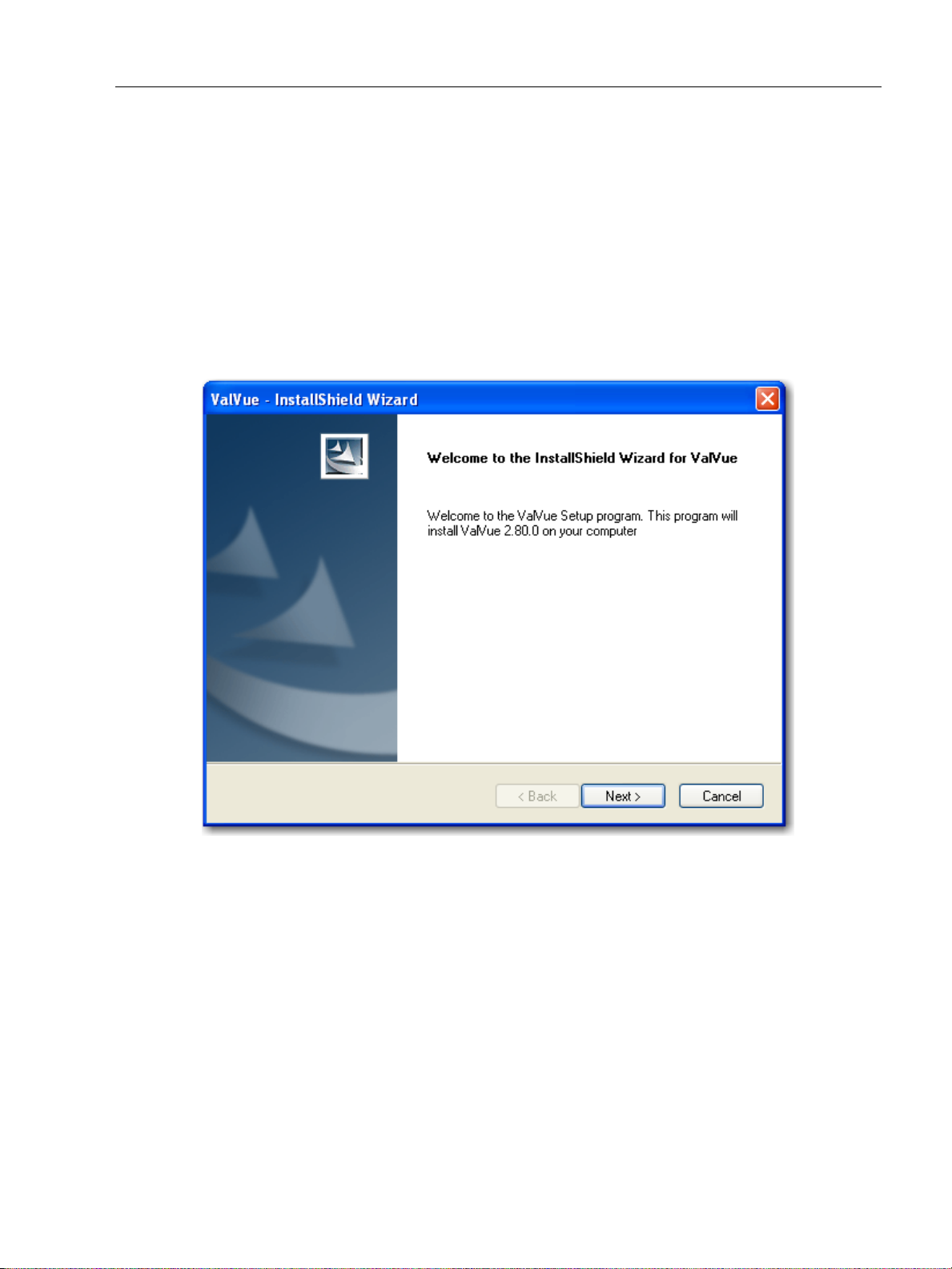
Installing ValVue
Installing ValVue
Use this procedure to install ValVue software. If the ValVue installer finds a previously
installed version of ValVue, it uninstalls the old version. A dialog box asks your permission to
uninstall. Run the installer again to install the new version.
1. Insert the ValVue installation CD into your CD-ROM drive.
2. Select Start->Run from the taskbar.
Select Enter or OK.
Follow the prompts on your screen to complete the installation process.
ValVue Software Installation and
Figure 1 ValVue Installation Wizard
21
Page 22
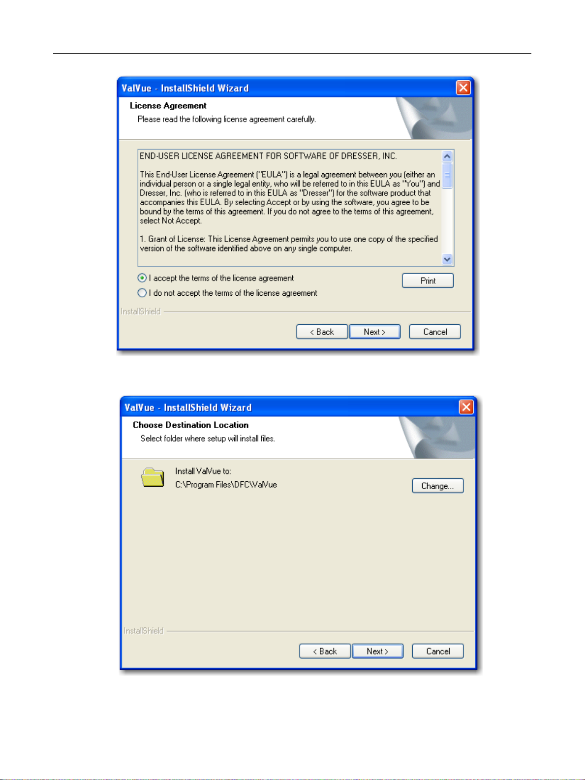
GE Oil & Gas
ValVue Digital Communications Software Ver. 2.80
Figure 2 License Agreement
Figure 3 ValVue Default Destination Location
22
Page 23
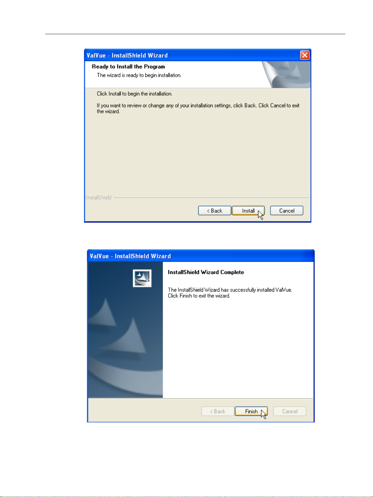
Installing ValVue
ValVue Software Installation and
Figure 4 Install ValVue
Figure 5 Finish Installation
23
Page 24

GE Oil & Gas
ValVue Digital Communications Software Ver. 2.80
Administration
An administrative program, ValVue 2 Administration, is installed along with ValVue. After
successful installation, the ValVue system administrator should change the default login and
password using the administrative program. There are two default login names installed and
they are both case sensitive (Table 1).
Table 1 Default Login Names and Passwords
Login Name Password Permission Level
admin (No password needed) 9
masoneilan new 8 (Used only for training)
Store the ValVue setup CD-ROM in a secure location to provide system security.
ValVue System Administration, Passwords, and Privilege Levels
In a system having many users with various levels of training and responsibility it is
recommended to restrict certain user’s access to a limited range of functions. Starting the
ValVue program requires a valid account with a user name and a password for each user. The
privilege level associated with a ValVue account determines which functions of the program
the user is allowed to access.
The ValVue Administration program, ValVue2Admin.exe, allows the administrator to perform
all user account administrative functions, run ValVue and control access to the functionality of
HART positioner. AMS handles security with passwords differently from ValVue. See the AMS
documentation.
The administrative functions include:
Adding new user accounts
Deleting existing user accounts
Changing existing user accounts
Adjusting privilege levels
24
Page 25
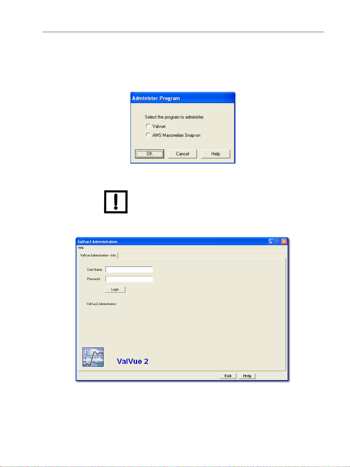
Starting Administration Program
Starting Administration Program
To start the ValVue Administration program:
1. Select Start > All Programs > Dresser > ValVue > ValVue Tools > ValVue
Administration and Figure 6 appears.
Figure 6 ValVue Administration Program Startup
NOTE System administration, users, and licensing for the AMS
ValVue Software Installation and
SNAP-ON differ from similar functions in ValVue. See the AMS
instruction manual.
2. Select ValVue and click OK and Figure 7 appears.
Figure 7 ValVue Administration Login
3. Enter admin as User Name. The system is case sensitive; you must enter the default names in lower case. Leave Password blank for the first time.
25
Page 26
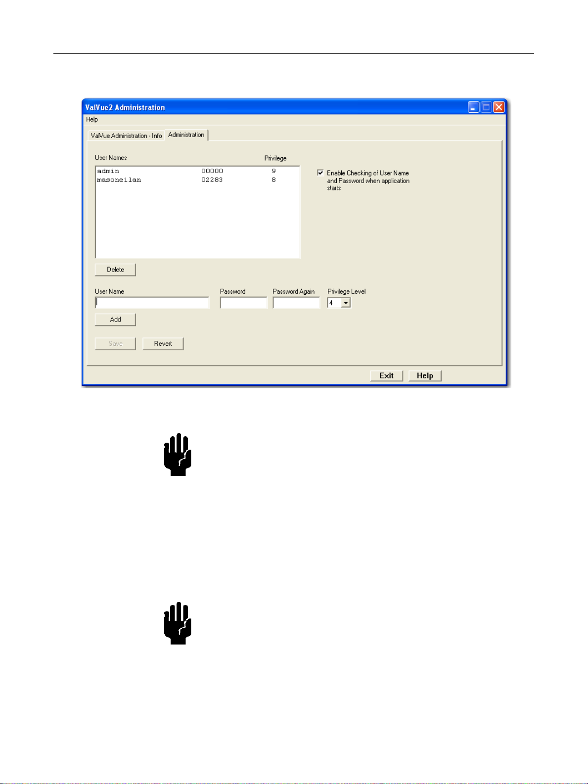
GE Oil & Gas
ValVue Digital Communications Software Ver. 2.80
4. Select Login to start an Administration window (Figure 9).
Figure 8 ValVue Administration Screen
CAUTION Use permission level 8 for training only. Level 8 allows the
positioner to be disconnected from the process control system.
The administration program, when first installed, contains two
accounts. One account is the administrator account that you are
using. The other account has User Name of masoneilan in lower
case and password of new also in lower case. The masoneilan
account is assigned privilege level 8 that allows use of the process
control simulator for training purposes. The process control
simulator duplicates, in software, a process with a dead time of
one second and a lag of five seconds. Never assign permission
level 8 to basic users.
CAUTION The administrator should change the login names and passwords.
Continued use of the login account names and passwords renders
the system insecure.
ValVue Lite does not require the administration program, and does not require passwords. If
restricted access is required, distribution of the ValVue Lite program software must be limited.
26
Page 27
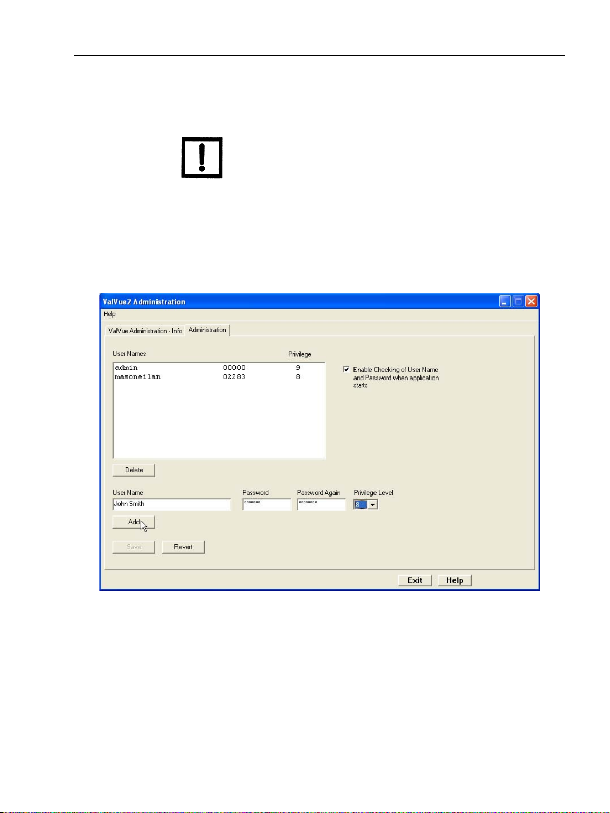
Add Users
Add Users
ValVue Software Installation and
To add users:
NOTE If you need to discard your changes click the Revert button.
1. Enter the User Name.
2. Enter a password in the Password field and re-enter the password in the Password Again field.
3. Assign a privilege level (refer to “Privilege Level” on page 29).
4. Select Add
Figure 9 Adding a ValVue User
5. Enter additional users.
6. Select Save and select Exit (Figure 10).
27
Page 28
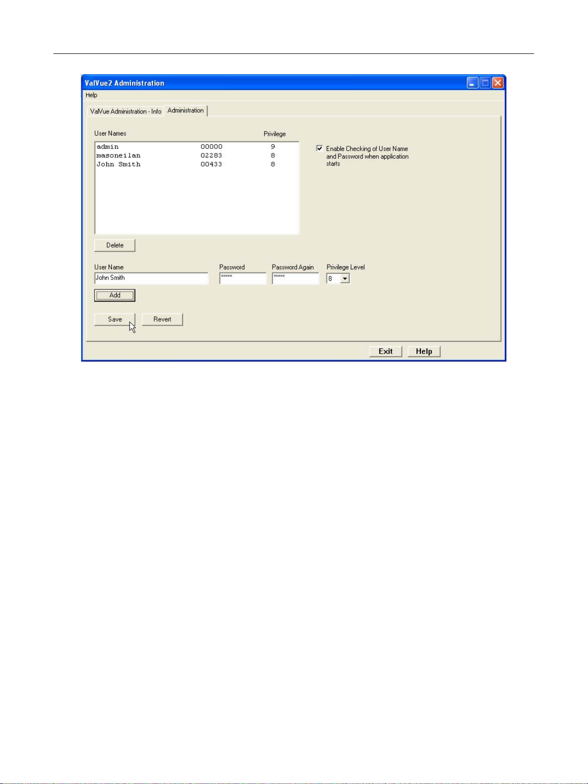
GE Oil & Gas
ValVue Digital Communications Software Ver. 2.80
Editing User Accounts
To edit a user account:
1. Select the account you need to edit .
2. Delete the selected account.
3. Create an account with the changes.
Deleting a User Account
To delete a user’s account:
1. Select the user account in the list box.
2. Select the Delete button.
3. Select Save to apply your changes.
4. Select Exit.
Figure 10 Saving New User
28
Page 29

Privilege Level
ValVue Software Installation and
Privilege Level
Each user is assigned an account with an associated privilege level associated. You provide
ValVue users an appropriate privilege level so you can keep field devices secure from the
actions of unknowledgeable or unauthorized users.
Privilege level ranges from 0 (lowest) to 9 (highest). Table 2 defines several privilege levels
that control access to specific functions of the ValVue program.
It is recommended that the administrator be assigned a second login name and password
with lower privilege, such as level 4, for routine use.
Privilege Level Details
Table 2 ValVue Privilege Levels
Security Level Description
Level 0 Allows you to login to ValVue only if the connected positioner is in normal operating
mode. You can send commands that replies with configuration, calibration, and
status information, but you cannot change any information. Level 0 users cannot
go to manual mode.
Level 1 Allows you access to either normal operating mode or manual mode. You can
transfer from one to another mode (i.e. you can take the positioner out of normal
mode and put it in manual mode). However, you cannot change the calibration or
configuration.
Level 3 Allows you to change the configuration or calibration values, but does not allow
you to perform operations that stroke the valve (Find Stops and diagnostics).
Level 4 Allows you to perform all operations except Save Factory standard valve signature
and Restore SVI Memory.
Level 8 This level is intended for training and should be used cautiously. It grants all of the
privileges of level 4 plus allows access to the simulation mode of the optional process controller. The process controller is an available option. The simulation mode
of the controller allows you to run the process controller without connecting a process variable input to the positioner and is useful for learning how to operate the
process controller. Never assign level 8 to ordinary users!
Level 9 Allows access to all positioner functions. In addition, it is the only level allowed to
login to the administration program. The administrator has an account of privilege
level 9. There must be at least one user of privilege level 9.
29
Page 30

GE Oil & Gas
Starting ValVue
The ValVue program provides a Windows based interface that can operate, configure,
calibrate, and diagnose positioners and controllers. ValVue can also communicate with other
HART devices at a basic level (using HART Universal Commands) as well. To communicate with
a
positioner, you need to connect the device to the computer RS-232 serial port through a
HART modem, or through an MTL multiplexor and an RS232-485 converter. When there is no
connected HART device, ValVue allows you to run offline with a simulated
ValVue provides an on-line help utility that provides information on how to use functions of
positioner with ValVue. To access the help utility, select the appropriate Help from the Help
the
menu in various ValVue screens. After completing the hardware connections, communication
with a
Always return control of the device to the control system before ending a ValVue
communications session. If communications to the
system failure, if Windows stops responding, always reboot the computer and return control
to the control system before ending the ValVue communication session
To start ValVue
positioner can begin.
ValVue Digital Communications Software Ver. 2.80
positioner.
positioner are interrupted by a computer
Double-click on the ValVue icon.
or
Select Start > Programs > Dresser > ValVue > ValVue.
Registering ValVue
When you start ValVue for the first time the registration window launches. ValVue software
must be registered to activate the permanent installation. ValVue can be used without
registration for 60 days. Registration allows the factory to keep track of all of ValVue users so
that we can notify you of any changes or important information about new software features
and updates. A registration card is included with the installation CD.
The software package contains a serial number. Keep a record of the serial number in a secure
location. Do not discard the registration card. To register your software, you must launch
ValVue to obtain an installation ID number, then contact the factory by mail, telephone, email
or Fax, and provide your name, company’s name, contact information, the CD-ROM serial
number, and the installation ID number from the ValVue login display. Contact information is
provided on the registration card that is part of the software package.
Your serial number is located on the ValVue package and on the enclosed sticker. Place the
serial number sticker on the detachable card included with the Registration Instruction card
and store the card in a secure location. You need the serial number to move ValVue to a
different computer.
30
Page 31

Registering ValVue
Masoneilan Software Registration Center provides you with software keys that you enter the
next time you run the program. Contact Software Registration Center for a new software key
if you are moving ValVue to a different computer or, if you do not have a serial number.
To register ValVue:
1. Start ValVue either by clicking on the desktop icon or using the Start programs selection.
2. When you start ValVue Figure 11 appears.
ValVue Software Installation and
Figure 11 ValVue Owner and Product Key Registration Window
3. Enter Name, Company and Serial Number and click OK.
31
Page 32

GE Oil & Gas
ValVue Digital Communications Software Ver. 2.80
Figure 12 Applying Owner and Product Key Information
The software key registration window appears (Figure 13).
4. If you need a software key for the Mux option, click the box next to Mux.
Figure 13 Software and Mux Key Window
32
Page 33

Registering ValVue
5. After selecting optional features, click Registration and Figure 14 appears.
ValVue Software Installation and
Figure 14 Registration Window
6. Enter your name and the name of your company. You are now ready to make contact with this information, to obtain your software keys. There are four methods shown on the Registration Instruction Card:
Phone
Fax
7. Click Save to File in Figure 14 to save your registration file and Figure 15 appears. Save the registration information in a text file.
33
Page 34

GE Oil & Gas
ValVue Digital Communications Software Ver. 2.80
Figure 15 Save Registration Information
Figure 16 appears.
Figure 16 Registration File Saved Dialog
8. To email the registration information click Yes.
9. When you select email registration info, ValVue launches your email service and
automatically attaches the registration and Masoneilan Software Registration Center
(Figure 17). Click Send to email the registration.
If your email program fails to start, contact the software registration center by the email
address, phone number, address, or fax number given on the registration card (contained
with the ValVue CD).
34
Page 35
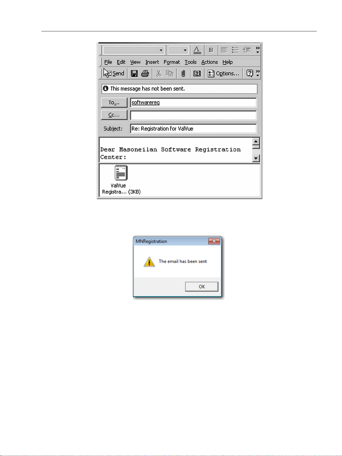
Registering ValVue
ValVue Software Installation and
A dialog indicating the email has been sent appears.
10. Click OK to close the dialog.
Entering Software Keys
After you have sent the registration info, you are provided you with software keys for ValVue
and optional features (when applicable).
Figure 17 Emailing Registration Info
Figure 18 Registration Email Sent Dialog
Once you have your key, enable the program by:
1. Start ValVue.
2. Choose View Registration from the Help menu.
35
Page 36

GE Oil & Gas
ValVue Digital Communications Software Ver. 2.80
3. Enter the Serial Number (if not already entered) and click OK. On the 2nd registration screen, enter the software key returned to you.
Figure 19 Entering Software Key
4. If you have the Mux option and need to enter the software key, click on the screen, under the Unlock Keys field and the field becomes active. Enter the Mux software key.
Figure 20 Entering Mux Unlock Key
36
Page 37

Using Unregistered Software
5. Click OK and Figure 21 appears.
Figure 21 Successful Registration Message
Using Unregistered Software
You can use ValVue full version, without a software key, for 60 days after initial installation.
Starting Unregistered Software
To start the unregistered version of ValVue:
ValVue Software Installation and
Double click on the ValVue icon.
or
1. Select Start >Programs->Dresser > ValVue > ValVue.
A dialog indicating the number of days remaining in the trial period appears, and then the registration window appears.
2. Click OK.
Offline Mode
There is an offline mode available in ValVue to work with a disconnected HART device.
The Offline options serve two purposes:
Viewing configuration, calibration and diagnostic data, for a positioner using a dump
Learn the features and functions of a positioner and ValVue
When a positioner is started in the Offline mode you are prompted to select a dump file with
a dp1 (or .dp2) extension that contains configuration and calibration data used for running
the device.
file (.dp1 or .dp2)
37
Page 38

GE Oil & Gas
Offline Operation
To run ValVue in offline mode:
1. Click a Tag in the Connected Devices screen and click the Select button (or double click the selected line). The HDLT Level transmitter offline file is also included. See the HDLT instruction manual.
A File Open window appears to select a dump file as a simulated device. The dump files are installed with ValVue in the same location as the program files (Figure 22).
2. Select the sub-folder for the selected device type, then select Data and then choose a file.
There is a default demo file that can be used for demonstration purposes. There can also
be files of actual devices in your plant that been saved in the default folder.
ValVue Digital Communications Software Ver. 2.80
Figure 22 Open Offline File
3. Click Open.
If you select a file for a device that is incompatible with the selected device, Figure 23 appears.
Figure 23 Incompatible Device/Data Warning
Go back and check that the subdirectory for the specific device type has been used.
38
Page 39

Offline Operation
Offline Mode
Selecting OK reopens the Open File dialog. Selecting the matching file type opens up Monitor
page. SVI II AP Offline appears in the top left corner, indicating the file that ValVue is using a
dump file to simulate operations.
ValVue Software Installation and
Figure 24 Offline Monitor Page
39
Page 40

ValVue Digital Communications Software Ver. 2.80
This page intentionally left blank.
Page 41

ValVue Setup
Overview
This section provides information on setting up ValVue. There are several features that you can
set up in ValVue before executing operation:
“Configure the Set Options” on page 41
“Configure Multiplexor Setup and Operation” on page 45
“Configuring Burst Mode” on page 51
Configure the Set Options
When login is complete, the Connected Devices page appears. To configure ValVue for your
system:
3
1. Right-click on the Connected Devices page, in the gray area (Figure 25).
Figure 25 Selecting Set Options
41
Page 42

GE Oil & Gas
ValVue Digital Communications Software Ver. 2.80
2. Select Set Options to open the Options dialog (Figure 26).
Figure 26 ValVue Options Dialog
3. Configure as required and click OK.
Figure 27 shows the dialog when PF-WHA-GW for a wireless gateway is selected. In this case
you need to configure the IP Address and Port.
42
Page 43

Configure the Set Options
ValVue Setup
Figure 27 ValVue Options for Wireless
Buttons and Fields
Com Port Select the COM Port on your PC that is connected to the HART
modem. If you’re not sure which COM port the modem is connected to, access Windows’ Device Manager to validate the com
port number assigned to the PC.
Hart Polling Option When more than one device is connected on a loop or if polling
addresses other than 0 have been assigned to devices, use these
fields. ValVue supports HART devices with non-zero polling
addresses and supports multiple positioners on the same loop (for
split ranging, for example). If neither box is checked, ValVue looks
for devices only at polling address 0. Click either:
From and choose an address range from 0 to 63. Choosing
a range limits scan time.
Specific and enter an address or addresses, where you
enter one or multiple addresses separated by commas. This
also limits scan time.
43
Page 44
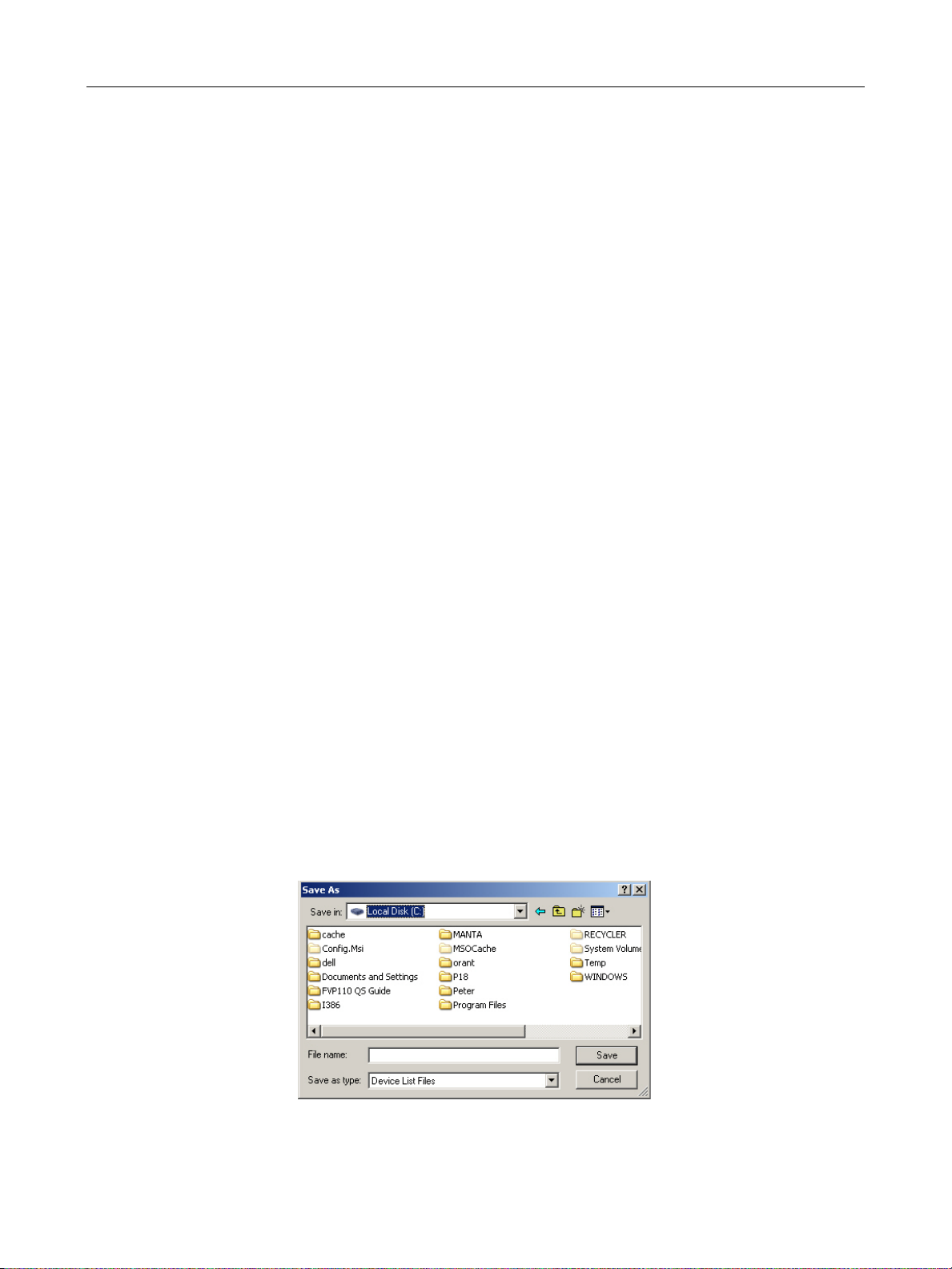
GE Oil & Gas
Master Mode ValVue communicates with a HART device as a primary master or as
ValVue Digital Communications Software Ver. 2.80
a secondary master. HART is a Master-Slave communication protocol, where the slave (field device) replies to commands sent by the
master. The HART protocol lets a device communicate simultaneously with two masters, as long as they are different Masters: one
being a Primary Master and the other being a Secondary Master. A
Primary Master is defined as a host (or system interface) that is connected permanently with a slave, such as a control system. A Secondary Master is a host (or interface) connected temporarily to the
slave (a handheld or laptop computer) and that is not part of the
control system.
When used with a multiplexor, operation is allowed when a second
HART master, such as a DCS system, is communicating. The ValVue
program must be configured to match the configuration of the multiplexor. If the multiplexor is a primary master, ValVue must also be
configured to be a primary master.
See “Configure Multiplexor Setup and Operation” on page 45.
Use HART server Check to use a HART server.
Using a Device List File When you select the Load Device Addresses from File option, each
time you connect a device to ValVue the address for the scanned
device is saved to a device list file. The device list file eliminates rescanning each time Connect is selected and is useful in a multiplexor
setup.
Unless Load Devices Addresses from File is selected as an option,
the device addresses used are temporary and ValVue rescans for the
device’s address for each program start. If selected, you designate
the file where the device list is saved. This device list file is read and
appears when the program starts. To change the device list file or
create a new one:
1. Click Load Devices Addresses from File, click New File and
Figure 28 appears.
Figure 28 Device List Save As Window
44
Page 45

Configure Multiplexor Setup and
Use Multiplexor Use this option to set ValVue for multiplexor operation. When
CAUTION Do not check Use Multiplexor unless ValVue is connected to
ValVue Setup
2. Navigate to the required directory to either locate the old device
list file, or to create a new one.
checked then the MUX Setup, and MUX Reset controls appear on
the Connected Devices page context (right click) menu.
This checkbox also activates the multiplexor pulldown list, Baud
Rate and Nodes Search. Multiplexor choices include:
MTL-AMS
MTL-Cornerstone
PF-2700F
PF-2700G
SoftMux
PF-WHA-GW
Multiplexor hardware.
Baud Rate Set a baud rate that is equal to the baud rate set on the multiplexor
hardware. The MTL multiplexor supports baud rates of 9600,
19200, and 38400.
Nodes Search Scan all nodes - Click this radio button and when you click Re-Scan
on the Connected Devices screen ValVue scans all 32 nodes to find
the connected devices.
Selected Nodes - Click this radio button and the Select list appears
for selecting a particular node (s) that are scanned when you click
Re-Scan on the Connected Devices screen.
Configure Multiplexor Setup and Operation
ValVue supports the MTL HART multiplexor to monitor and operate many HART devices from
a single computer.
45
Page 46

GE Oil & Gas
Mux Setup
ValVue Digital Communications Software Ver. 2.80
The MTL 4840 HART maintenance system is a widely used multiplexor for communicating with
HART instruments. Connected to a computer serial port with a RS232⁄RS485 converter, the
multiplexor is capable of supporting up to 31 nodes, each with the capability of supporting up
to 16 sub nodes. Each sub node can control 16 loops. Therefore, the multiplexor provides the
potential to communicate with a maximum of 7936 HART loops, i.e., 31 (nodes) x 16 (sub
nodes) x 16 (loops) using one computer interface. Additionally, the multiplexor supports the
multidrop connection of HART devices on a single loop. Therefore, using the multidrop feature
it is possible to expended capacity of a system beyond 7936 HART devices.
For more information regarding the MTL multiplexor, refer to the MTL documentation.
Using the multiplexor capability of ValVue and the MTL multiplexor, monitoring and
communicating with many SVI’s and other HART devices is possible.
To setup the nodes used on the MTL multiplexor:
1. After you have checked Use Multiplexor and selected the baud rate and node in the Set Options (see “Use Multiplexor” on page 45), select Connected Devices.
2. Right-click on the Connected Devices page background and Select Mux Setup on the context menu.
Figure 29 Context Menu with Mux Functions
Figure 30 appears and prompts for the nodes to be configured.
46
Page 47

Mux Setup
ValVue Setup
Figure 30 Device Address
3. Enter a number between 1 and 31 for the desired node and select OK and Figure 31. The
node address must match the DIP switch setting on the Mux hardware.
The Multiplexor Setup dialog appears (Figure 31).
Figure 31 Options and Mux Setup
Buttons and Fields
Tag Enter up to eight characters long and is used to identify the MTL
multiplexor node in the system. The tag is displayed in Device List
box on Connected Devices screen.
Descriptor Enter a description with up to 15 characters for the MTL multi-
plexor node.
47
Page 48

GE Oil & Gas
Retry Count Enter the number of times the multiplexor retries sending a com-
Preamble Count Enter the number of preambles. A Host using the HART protocol
Scan Age Time Enter the maximum scan time in seconds that scan data remains
ValVue Digital Communications Software Ver. 2.80
mand to a Hart device before returning with an error. The valid range
for this number is 0 to 5. The recommended number for use with Val-
Vue is 3.
sends a short preamble string of characters at the beginning of each
communication to wake up the other device. The number of preambles prefixed to each Hart command sent to a device varies from
device to device. The valid range is 2 to 20. Recommended values for
this parameter are 3 to 5 when using the Mux.
valid. An error is returned when scan data is requested more than
the age time since the data was last updated. This parameter is
available here to set for other applications that use the multiplexor.
ValVue does not support the scanning feature.
Master Mode Primary Master/Secondary Masters
Search Method When building a device list, the multiplexor can use one of three
Scan Option The MTL multiplexor has the capability to continually scan the con-
Select such that ValVue is configured to be the same type of master
as the multiplexor. Use both the Options and Multiplexor Setup dialogs to check and compare the selection. Both can be primary or
both can be secondary; they cannot be different.
ways:
Polling Address 0 only: This method looks only at polling
address 0 for each loop. Any devices on a loop with a
non-zero polling address are not found.
One Device: For each loop, all polling addresses are searched
until a device is found. The multiplexor does not continue the
search on a loop after the first device is found.
Multidrop: Polling addresses 0 - 31 are searched as per the
selections on the Options dialog ( “Configure the Set Options”
on page 41), and any devices found are added to the device
list.
nected Hart devices to report the results. ValVue does not use this
feature, but the option is provided to configure the multiplexor as
needed by other applications.
Mux Reset
Click and the multiplexor rebuilds its table of live devices. You are prompted for the node that
is to be reset. When reset, the multiplexor node re-scans all of the devices connected to it and
depending upon the options set for the multiplexor, can take some time to complete. If
hardware has been added to the Mux or connected to different Mux channels a rescan must
be performed before the ValVue re-scan can be used.
48
Page 49

Mux Reset
The Mux Reset is necessary when adding or removing HART devices on a Mux network. This
function updates the Mux’s Look Up Table utilized by ValVue to map devices.
NOTE The Mux hardware re-scan is different from the re-scan
performed by ValVue from the Re-scan button. No
communication between ValVue and any device takes place on
the node until the reset is completed. This can take several
minutes, depending on MUX loading.
Use the multiplexor to request information about HART devices
1. Select the MUX Reset popup menu function to issue a reset command to a node of the
multiplexor. You are prompted for the node that is to be reset.
2. Reset the node. The multiplexor node re-scans all of the devices connected to the node
(this hardware rescan is different from the rescan done by ValVue from the Rescan
right-click menu). Depending upon the options set for the multiplexor, this can take a
while to complete. No communication can be done with devices on the selected node
until the reset is completed.
3. Select Rescan popup menu function to build a device list.
ValVue Setup
To find a device by its tag
A device list is arranged in the order found on the multiplexor’s channels. This list can be
very long if there are many connected devices.
1. Select the Find by Tag button to open a text entry dialog.
2. Enter a tag name for ValVue to search the device list for a device with a matching tag. If
found, the device is selected and the window scrolled so that its line is visible.
3. Selecting the Rescan popup menu function causes ValVue to build a new device list. All
nodes are polled. If there are a large number of devices connected to the multiplexor,
this function can take some time to complete. When the re-scan is completed, save the
device list to a file so that rescanning is not necessary every time ValVue is started.
49
Page 50

GE Oil & Gas
Troubleshooting ValVue Mux
Table 3 Troubleshooting ValVue Used with Mux
Problem Cause Corrective Action
ValVue Digital Communications Software Ver. 2.80
No devices found
Mismatch of the baud rate setting between the Mux and ValVue
HART converter (RS-232 to
RS485) not working properly.
Expected device is not found in
Connected Devices list
Devices all have the same tag
name in Connected Devices
Both ValVue and AMS
are connected to the
Mux
The MTL Mux is configured for AMS mode
Mux Use Set Options in ValVue to match the setting of
Check for loose wires
Check for power
cabling between converter and Mux
Device was added
after the Mux performed its last scan
ValVue and Mux are
not configured as the
same type of master
Connect ValVue to the device with a modem. If
the installation is correct connect the input to the
MTL 4046P Isolator. In a general purpose system,
connect directly to the device wires.
Reconfigure the Mux for Cornerstone communications mode with MTL provided software.
the Mux. Refer to the dip switch setting on the
Mux.
Check configuration of converter. Refer to the
manufacturer’s instructions.
Click the Rescan mode Powering on/off/on the
Mux can also help. However, this impacts the
communication on all devices.
Set Mux and ValVue so both are Primary Master or
both are Secondary Master.
50
Page 51

Configuring Burst Mode
Configuring Burst Mode
The Burst mode is a mode where the HART device continuously sends out data without
being polled by a Master. This mode is useful only for devices that are passive (i.e. not a HART
master), such as a HART to Analog converter (SPA from Moore Industries, Tri-Loop by
Rosemount). It is not necessary to set the burst mode to allow communications with a
control system since the control system is a master capable of polling the device. Turning on
Burst mode in cases where it is not required affects the communication bandwidth.
Figure 4 provides a summary of the data returned from the Burst mode (HART Command #3
equivalent to Process-Vars-Current).
Table 4 Burst Mode Data Return
Variable Description Units/Range
SVI II AP (firmware 3.1.1, 3.1.2, 3.2.1, 3.3.3 and 4.1.1), SVI II (Firmware 12x) or SVi1000 (1.1.1)
PV (Primary Variable): Valve position 0-100%
ValVue Setup
SV (Secondary Variable) Actuator Pressure 0-150psig
(0-120psig for firmware 12x)
TV (Tertiary Variable) Not used (Future)
QV (Quaternary Variable) Not used (Future)
SVI
PV (Primary variable): Valve position 0-100%
SV (Secondary variable) Actuator Pressure 0-150psig
TV (Tertiary variable) Process Variable According to device setting
QV (Quaternary variable) Controller setpoint According to device setting
HDLT
PV (Primary variable): Level According to device setting
SV (Secondary variable) Actuator Pressure 0-150psig
TV (Tertiary variable) Controller Setpoint According to device setting
QV (Quaternary variable) Board Temperature According to device setting
Use this procedure to configure a burst mode.
1. Select the intended device from the Connected Devices page.
51
Page 52
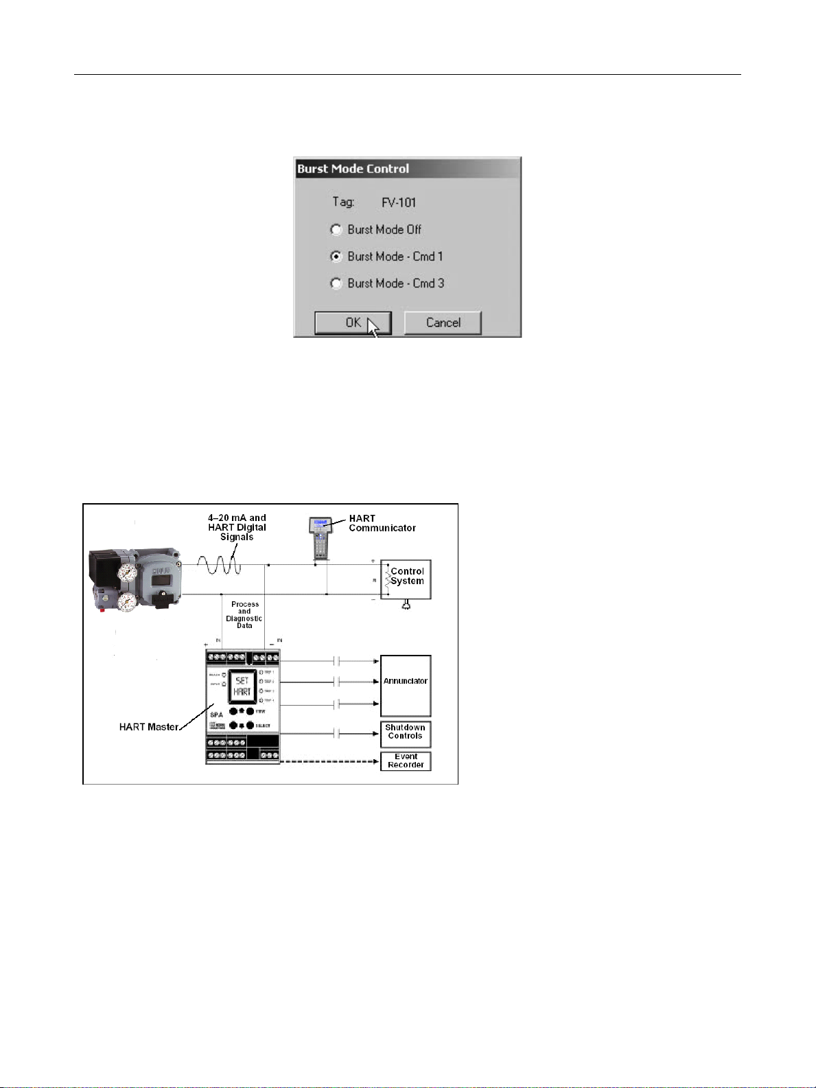
GE Oil & Gas
Connecting the SPA with the SVI II
Connecting the SPA with the SVI II
• Valvue must be set as as
a secondary master if the
SPA is in polling mode to
be able to connect
•PV = Position
• SV = Actuator Pressure
• TV = Not Defined Yet
• QV = Not Defined Yet
The on/off contacts can be triggered from
the status bits sent with every message.
The module must be configured to let it know
which bit will trigger the contact.
ValVue Digital Communications Software Ver. 2.80
2. Right-click on the gray background of the window and select Burst Mode Control and Figure 32 appears.
Figure 32 Burst Mode Control
3. Select the desired command.
4. Select OK.
Figure 33 Burst Mode Configuration
52
Page 53

Connecting Devices
Connected Devices
After you have successfully logged in, ValVue opens the Connected Devices window and
searches the com port for connected devices. The devices that are found are listed. To stop the
searching process, select the Stop button. The list includes offline device files and live devices.
Scanning can take a few seconds if multidrop is selected. When a Multiplexor is used, the
process can take a longer time, depending upon how many devices are connected. If the device
file is enabled it displays previously scanned devices listed in the device file.
4
Figure 34 Connected Devices
53
Page 54

GE Oil & Gas
Selecting a Device
1. Click on the device you wish to run.
2. Click Select Device.
or
Double-click on a Tag name.
When connected through a multiplexor, any device connected to the multiplexor can be
selected. If the device is an SVI II AP, ValVue opens the device at the Monitor page.
When connected through a multiplexor, the select action is ignored if the selected device is a
node or sub node. If the selected HART device is not a Smart Valve Interface, only universal
HART messages are sent.
Find by Tag
Use this procedure to save scan time with the Mux when there are multiple devices.
To find a device by its tag name:
ValVue Digital Communications Software Ver. 2.80
Re-Scan
1. Select Find by Tag and Figure 35 appears.
Figure 35 Input Value
2. Enter a tag name and click OK.
The software searches for a device with a matching tag. When found, the device is selected.
To build a new device list:
1. Select Re-scan:
In the direct-connect configuration of ValVue all polling addresses are checked if the
options allow multidrop.
54
Page 55

Re-Scan
Connecting Devices
In the multiplexor configuration of the program, all nodes are checked. If there are a
large number of devices connected to the multiplexor, this function takes time to
complete.
2. When the rescan is completed, you can save the device list to a file so that rescanning is
not necessary every time ValVue is started. If there is only one device on the loop, select
Stop when it has been found to save scan time.
55
Page 56

ValVue Digital Communications Software Ver. 2.80
This page intentionally left blank.
Page 57

Advanced Setup with
NOTE
ValVue
Methods to Set Up the SVI II AP
There are two methods of setting up the SVI II AP with ValVue:
1. Run Setup Wizard from the Monitor screen.
2. Advanced Setup of the SVI II AP by and advanced user.
The Setup Wizard automatically runs through the specified setup routines and is executed from
the Monitor screen. The Setup Wizard is the preferred and recommended method for initializing
an SVI II AP (refer to “Setup Wizard” on page 82 of this manual for instructions).
Advanced Setup
5
An advanced user may want to customize the setup beyond the parameters provided by the
Setup Wizard.
Steps to Set Up SVI II AP
To set up the SVI II AP:
1. Configure the SVI II AP.
Read and Set Configuration Parameters
2. Calibrate the SVI II AP.
a. Run Find Stops or Manual Find Stops
b. Run AutoTUNE
c. View Calibration Parameters
Before making any configuration or calibration changes ValVue must be in Setup mode.
57
Page 58

GE Oil & Gas
Configuration Parameters
Refer to “Configure Screen” on page 99 of this manual for all configuration instructions.
Calibration Steps
Run Find Stops
To determine valve position, the positioner must measure and save the closed and open
positions of the valve. This can be done automatically by running the Find Stops procedure
from the Calibrate screen.
The SVI II AP first exhausts the actuator and measure the position, then fills the actuator and
measures the position. From these measurements the valve position can be determined.
Correction can be made for nominal valve travel if it is less than full travel.
To run Find Stops from the Calibrate screen:
1. Right-click and select Run Find Stops.
ValVue Digital Communications Software Ver. 2.80
Figure 36 Selecting Run Find Stops
58
Page 59
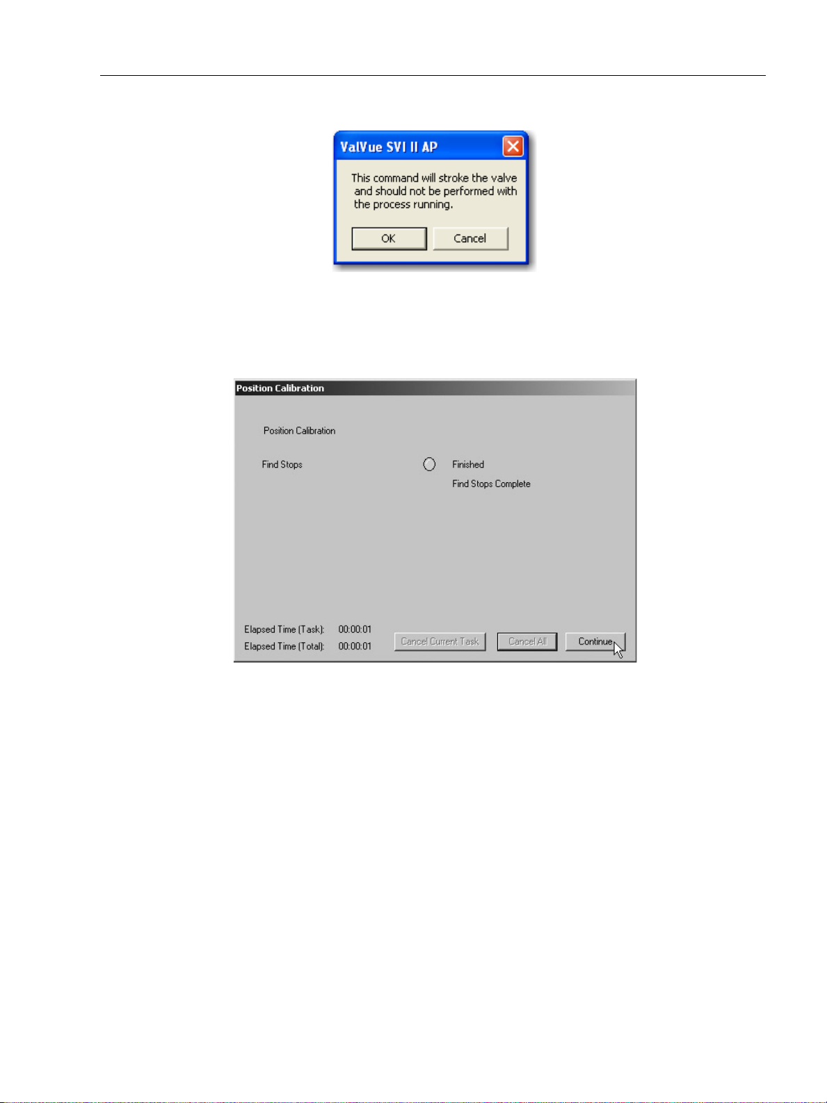
Manual Find Stops
Figure 37 appears.
2. Click OK.
When Find Stops is complete, Figure 38 appears.
Advanced Setup with ValVue
Figure 37 Starting Run Find Stops
3. Click Continue to close the dialog and return to the Calibrate screen.
Manual Find Stops
On some actuators, it is possible that the automatic Find Stops procedure will not find the
correct end positions of the travel. A semi-automatic method of calibrating the stop
positions is provided.
Manual Find Stops moves the valve to full closed and you are asked to respond when the
valve has reached the closed position. The valve is then moved to full open and you are
asked to respond when the valve has reached the full open position.
For some valves where the travel exceeds the nominal travel of the valve, see “Open Stop
Adjustment” on page 61 for details about how to trim the open stop.
Figure 38 Starting Run Find Stops
59
Page 60

GE Oil & Gas
ValVue Digital Communications Software Ver. 2.80
To run Manual Find Stops:
1. Right-click and select Manual Find Stops (Figure 39).
Figure 39 Selecting Manual Find Stops
Figure 41 appears.
Figure 40 Stroke Valve Dialog
60
Page 61

Open Stop Adjustment
2. Click OK. ValVue moves the valve to the fully closed position and Figure 41 appears.
Observe the valve until it is fully closed.
3. Click OK. ValVue moves the valve to the fully open position and Figure 42 appears.
Observe the valve until it is fully open.
4. Click OK.
Advanced Setup with ValVue
Figure 41 Valve Closed Dialog
Open Stop Adjustment
Recomputes the position scale so that at the value entered in the open stop adjustment edit
box as a percent of full stops, the position reads 100%
In some valves the travel exceeds the nominal valve travel. The SVI II AP allows you to
compensate for this so that the valve position reads 100% at the nominal travel.
To make this correction:
1. Enter 100 in the Open Stop Adjustment edit box.
2. Select Find Stops from the context menu.
3. Return to manual mode and adjust the valve to its nominal travel and note the position
reading.
Figure 42 Valve Open Dialog
61
Page 62

GE Oil & Gas
Full Travel
After Open Stop
Before Open Stop
0
100%
4 mA
20 mA
0
100%
4 mA
20 mA
ValVue Digital Communications Software Ver. 2.80
4. Return to calibrate mode, enter the position that was measured at nominal travel into the Open Stop Adjustment edit box.
5. Select Open Stop Adjustment from the menu. The valve now reads 100% at the nominal travel of the valve.
Figure 43 Open Stop Adjustment Diagram
62
Page 63

Tri-Loop Configuration
TRI-LOOP
MODEL 333d or 333u
Ch 3 Ch 2 Ch 1
- + - + - +
Comm Burst Input
- + - +
SVI II
+ -
Loop
Power
4-20mA
Analog
Output
Analog
Input
+ -
+ -
24Vdc
SVI II Configur a t ion:
HART Address = 0
Set BURST MODE to HART cmd #3 (with ValVue) or PROCESSVARS CURRENT (with Handheld or DD enabled Host)
PV is Valve Position (0-100%)
SV is Actuator Pressure (0-120 psi)
TV = Not Used
QV= Not Used
TRI-LOOP Setup
HART address =1
CHANNEL = ENABLE
Variable = PV
Upper Range Value = 100
Lower Range Value = 0
Units: %
250ohm
Tri-Loop Configuration
Figure 44 is a simplified schematic showing the SVI II and Tri-Loop and a control system
connection
The input channel from the control system must have an impedance of at least 250 Ohms or
else the HART signal becomes attenuated and the Tri-Loop won’t function properly. Also,
channel one must be enabled and set for Primary Variable with a range of 0-100%. You can
enable channel 2 and 3 even if you don’t connect them.
NOTE Consult the TRI-LOOP instruction manual for wring diagrams.
Advanced Setup with ValVue
Masoneilan is not responsible for improperly wiring the
TRI-LOOP. This document simplifies the setup requirement of an
SVI II with a device such as a TRI-LOOP. A resistor might be
required on the positive leg of Channel 1 to limit the current to
the TRI-LOOP.
Figure 44 Tri-Loop Configuration
63
Page 64

ValVue Digital Communications Software Ver. 2.80
This page intentionally left blank.
Page 65

Advanced Performance
Digital Positioner with
Remote Sensor
SVI II AP Software Manual
SVI II AP Software Manual
65
Page 66

ValVue Digital Communications Software Ver. 2.80
This page intentionally left blank.
Page 67
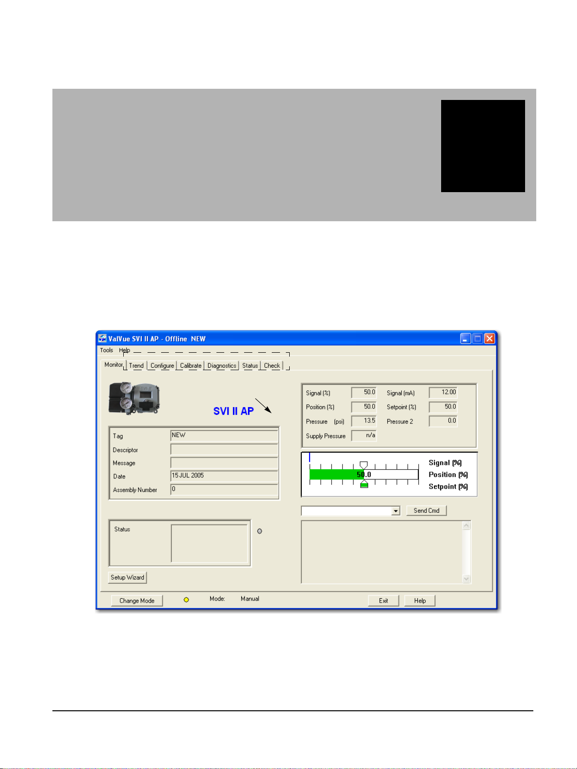
ValVue SVI II AP Work
Clicking on Tabs selects other ValVue Screens
Right clicking on background
displays the Screen related menu
Context-Sens itive Help.
Environment
Overview
This section describes the working environment of ValVue and how to accomplish SVI II AP tasks.
After you have successfully launched and logged into ValVue and selected a device the Monitor
screen appears (Figure 45).
1
Figure 45 ValVue Work Environment
67
Page 68

GE Oil & Gas
Working in ValVue
ValVue is set up as a typical Windows program, with tabs, menus, dialogs, windows and
toolbars. After you have successfully logged into ValVue, the selected device appears in
ValVue’s Monitor screen. You can either perform operation on the Monitor screen or select
another screen to display another ValVue screen.
Toolbar
The toolbar at the top of every ValVue screen has two menu items; Tools and Help.
Tools Menu
The Tools menu changes according to the selected screen.
Help Menu
The Help menu is the same on every screen and contains:
ValVue Digital Communications Software Ver. 2.80
Help – launches the help file table of contents
Firmware Info – displays information about the firmware loaded into the SVI II AP
About – displays information about ValVue
68
Page 69

ValVue Help
Accesses Active Screen Context Sensitive Help
ValVue Help
ValVue offers help in many forms. Help changes according to the active screen. Every screen
has access to the entire ValVue Help system through the Help command button located at
the bottom of every screen and through the Help menu located at the top of every screen.
Each screen also provides context sensitive Help that is pertinent to the active screen.
ValVue SVI II AP Work
Figure 46 Accessing Context Sensitive Help - Tools Menu
69
Page 70

GE Oil & Gas
Accesses Active Screen Context Sensitive Help
ValVue Digital Communications Software Ver. 2.80
Exit
Clicking Exit quits the program.
Change Mode
The Change Mode button located at the bottom left of all SVI II AP screens allows you to
change the operating SVI II AP mode. There are three operating modes:
Normal - In this mode the SVI II AP follows the 4 - 20 mA input signal and positions the
valve accordingly (indicator green).
Manual - in this mode the valve setpoint is set by the valve software, the local
pushbutton or a HART compatible Host system. When changing to this mode the
setpoint becomes the actual position.
Setup - In this mode you can set calibration and configuration parameters.
Additionally, for SVI II AP, you can step response tests, and positioner signatures
(indicator yellow).
Figure 47 Accessing Context Sensitive Help - Right Click Menu
Failsafe Mode
Failsafe – When the SVI II AP cannot operate correctly the device goes to the failsafe
position and remains in the failsafe mode until the user intervenes (indicator red).
70
Page 71

ValVue Screens
ValVue Screens
There are seven screens, correlating to the seven tabs available at the top level of ValVue:
Monitor - Use this screen to adjust current operating parameters of the selected SVI II
AP, perform HART commands and run positioner setup (See “SVI II AP Monitor
Screen” on page 73).
Trend - Use this screen to view in a graphical format the live operation of the selected
SVI II AP and capture the current data as a bitmap and save it to the computer
clipboard. You can then paste the graphical contents into any program that accepts
a bmp file; e.g. Microsoft Word, Excel, Power Point, etc.
Configure - Use this screen to view and adjust the current SVI II AP configuration
parameters. To adjust the positioner configuration, ValVue must be in the Setup or
Manual mode.
Calibrate - Use this screen to view and calibrate the stop positions and the feedback
control parameters (PID tuning parameters).
Diagnostics - Use this screen to view continuous diagnostics information and
perform diagnostic tests.
ValVue SVI II AP Work
Status - Use this screen to see the operating and internal status of the SVI II AP.
Check - Use this screen to monitor some of the basic parameters. This screen is used
primarily for troubleshooting.
71
Page 72

ValVue Digital Communications Software Ver. 2.80
This page intentionally left blank.
Page 73

SVI II AP Monitor
Send Command Display Window
Send Command Menu
Positioner Indicator
Positioner Operations
Positioner Tag Information
Status Display
Launch Setup Wizard
Screen
What You Can Do on the Monitor Screen
The Monitor screen is the first window displayed on starting ValVue. From the Monitor screen,
you can view the basic functions of the SVI II AP including; tag and identification, characteristics,
setpoint, position, and status. The Setup Wizard provides for rapid setup of the positioner in four
easy steps. You can:
Monitor the live operation of the SVI II AP Monitor the current positioner
2
characteristics
Send a HART command and view the
result
Generate reports Run the Setup Wizard
View the Position Indicator
(graphical representation)
Figure 48 Monitor Screen
73
Page 74

GE Oil & Gas
ValVue Digital Communications Software Ver. 2.80
Button and Fields
Positioner Tag Information
Tag A user-assigned name for the valve with a maximum eight characters.
The value appears in many views but can only be changed from the Configure
screen (see “What You Can Do on the Configure Screen” on page 99), using the
Setup Wizard (see “Setup Wizard” on page 82) or using a command ( “Changing
Tag Information on the Monitor Screen” on page 78).
Long Tag A user-assigned name for the valve with a maximum thirty two characters. Only
available for HART 6.
Use this field for any information desired. The value appears in many views but
can only be changed from the Configure screen (see “What You Can Do on the
Configure Screen” on page 99).
Descriptor A user-defined field with up to 16 characters. This field is commonly used to
describe valve use.
The value appears in many views but can only be changed from the Configure
screen (see “What You Can Do on the Configure Screen” on page 99), using the
Setup Wizard (see “Setup Wizard” on page 82) or using a command ( “Changing
Tag Information on the Monitor Screen” on page 78).
Message A user-defined field with up to 32 characters. Use this field for any information
desired.
The value appears in many views but can only be changed from the Configure
screen (see “What You Can Do on the Configure Screen” on page 99), or using
the Setup Wizard (see “Setup Wizard” on page 82).
Date Use the date field as needed. The preferred format is dd MMM yyyy (e.g. 14 NOV
2001). The program also accepts dates formatted as dd/mm/yy (e.g. 14/11/01).
Years greater than 70 are assumed to be in the 1900s and years 70 or less
assumed to be in the 2000s. The day precedes the month. Dates as dd/mm/yyyy
are also accepted.
The value appears in many views but can only be changed from the Configure
screen (see “What You Can Do on the Configure Screen” on page 99), using the
Setup Wizard (see “Setup Wizard” on page 82) or using a command ( “Changing
Tag Information on the Monitor Screen” on page 78).
Status Display Displays health indicators. When there is a fault code from the SVI II AP, Addi-
tional Status Available appears.
The status block also contains other status codes returned by HART. These
include Configuration Changed, Device malfunction, and Variable out of limits.
Assembly Number A user-assigned number. Value can be between 0 and 16,777,215.
Use this field for any information desired. The value appears in many views but
can only be changed from the Configure screen (see “What You Can Do on the
Configure Screen” on page 99) or using the Setup Wizard (see “Setup Wizard”
on page 82).
74
Page 75

What You Can Do on the Monitor
Positioner Operations
Signal Indicates the input analog signal expressed in % and in mA of the configured
Position Indicates the actual valve position in % of valve opening. 0% is always closed
Setpoint In NORMAL mode, the setpoint is the target position based on the characterized
Pressure The SVI II AP continuously monitors the actuator pressure and displays accord-
Position Indicator This shows the valve position graphically and consists of three parts:
SVI II AP Monitor Screen
signal range.
and 100% is open. Because the travel of a valve may exceed its nominal travel,
positions greater than 100% are possible (see “Open Stop Adjustment” on
page 61).
input. In MANUAL mode, it is the target position to which the SVI II AP is controlling the valve. The manual setpoint may be changed by dragging the lower
thumb on the position indicator.
ing to the configured units (psi, bar, or kPa).
The upper part contains an indicator showing the value of the input
signal. In Normal mode this is the position setpoint. WARNING! - In manual
mode, this is the position that the valve moves to if normal mode is selected.
The center green bar shows the valve position in percent. The numerical
valve position is shown in the center.
The lower part contains an indicator (that can be dragged when active)
showing the valve setpoint. In operating mode, this is the same as the signal. In manual mode it is the valve setpoint. You can drag the indicator to
change the valve setpoint. While dragging, the number in the center bar
shows the manual setpoint that is selected when you release the indicator.
Send Command
menu
Send Command
Display window
Setup Wizard button Click to launch the Setup Wizard ( “Setup Wizard Selections” on
Use this pulldown to send HART commands whose responses are seen in the
Send Command Display window.
Displays results of HART commands.
page 83).
75
Page 76

GE Oil & Gas
Position Indicator Active (Manual Mode)
Changing the Setpoint
To change the manual setpoint the SVI II AP must be in manual mode. There are three ways to
change the position indicator:
1. Entering the setpoint value in the Setpoint dialog.
2. Dragging the position indicator.
3. Left clicking on either side of the position indicator modifies the setpoint by 5%.
ValVue Digital Communications Software Ver. 2.80
Entering Setpoint Value
To enter a value for the position indicator setpoint:
1. Right-click inside the position indicator area and Figure 50 appears.
2. Enter the setpoint percentage and click OK.
Figure 49 Position Indicator Active
Figure 50 Changing Position Indicator
76
Page 77

Status on the Monitor Screen
Status Display - Additional Status Available
Status on the Monitor Screen
The SVI II AP provides several health indicators. When there is a fault code from the SVI II AP
Additional Status Available appears.
To retrieve fault codes:
1. Select Read Status from the Send Command drop pulldown list.
2. Click Send. The results appear in the lower left box. The fault codes also appear on the
Status screen.
SVI II AP Monitor Screen
Figure 51 Monitor Screen - Additional Status Available
77
Page 78
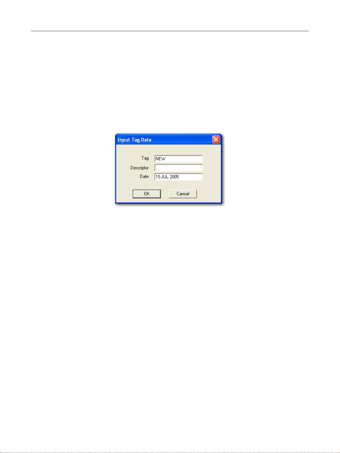
GE Oil & Gas
Tag Information
Changing Tag Information on the Monitor Screen
There are two methods of changing Tag Information on the Monitor screen:
Activate the Setup Wizard and execute Step 1. See “Setup Wizard Step 1” on page 83.
Use a command:
1. Select the Write Tag and Descriptor command from the command drop down list and appears.
ValVue Digital Communications Software Ver. 2.80
Figure 52 Input Data Tag
3. Enter the Tag information in the dialog box and click OK.
78
Page 79

Send Command
Send Command
You can send HART commands to the SVI II AP and view the results in the box below the
Send Command pulldown list. To send a command:
1. Select the command from the drop down list (Figure 53).
SVI II AP Monitor Screen
Figure 53 Selecting a Command to Send
2. Click Send Cmd button (Figure 54).
Figure 54 Executing Send Command
79
Page 80

GE Oil & Gas
ValVue Digital Communications Software Ver. 2.80
3. Read the results below (Figure 55).
Figure 55 Send Command Results Displayed
List of Available HART Commands
When you click on the drop down arrow, ValVue displays the available HART commands. Scroll
through the list until you locate the command you wish to execute:
000 Read Identifier - Returns the unique identifier from the device including the device
ID, device type, and the manufacturers ID.
001 Read Primary Variable - Returns the position in percent open.
002 Read Current - Returns the input signal in mA.
003 Read All Variables - Returns the input signal and the position in percent open
011 Read ID from Tag - Prompts the user for a tag name. The tag name is sent in a
HART command and if received by a device with a matching tag name, the ID of the
device is returned. The format of the ID is the same as command 001 Read Identifier.
012 Read Message - Reads the message that was stored in the device when it was
configured
013 Read Tag & Descriptor - Reads the tag name, date, and the descriptor that was
stored in the device when it was configured
016 Read Assembly Number - Reads the final assembly number that was stored in the
device when it was assembled at the factory
80
Page 81

List of Available HART Commands
017 Write Message - This command allows the user to enter a message (up to 32
characters) that is stored in the SVI II AP.
018 Write Tag & Descriptor - This command allows the user to enter a tag name (up
to 8 characters) and a description (up to 16 characters) that are stored in the
SVI II AP.
19 Write Final Assembly - This command allows the user to enter an identifying
number (0 to 16 million) which is stored in the SVI II AP.
038 Reset Configuration Changed Flag - This command sets the HART configuration
changed bit back to 0. The bit is set whenever a value in the device has changed.
072 Squawk - Send this command using ValVue and a specific device audibly
indicates the reception of the command.
210 Read Configuration - Reads the configuration data from the device and displays
it in the response box. The data includes all of the data describing the device set on
the Configure screen including Air-To-Open/Air-To-Close, Tight Shutoff status,
Software Position Limit Stops, etc.
200 Read Option Configuration - Reads basic (hardware) configuration information
about the positioner.
SVI II AP Monitor Screen
211 Read Custom Characterization – Reads the custom characterization information
about the positioner.
212 Read Error Limits - Reads and displays the position range and time-outs
associated with position and pressure errors
213 Read Calibration Data - Reads and displays the input signal that corresponds to
the open and closed positioning of the valve.
216 Read PID - Reads and displays the valve positioning tuning parameters
136 Read Status - Reads and displays the status flags. These flags describe error
conditions that have occurred since the last time they were cleared. See “Status
Code List” on page 150 of this manual for a complete list of possible codes.
138 Clear Status - Clears the status flags. See also “Status Code List” on page 150.
142 Read Switches - Reads the status of the contact switches
139 Read Continuous Diagnostic Data - Reads and displays the continuous
diagnostic data including number of full strokes the valve has made, the number of
cycles (direction changes), the time the valve has spent open, the time the valve has
been closed, and the time the valve has spent throttling near the seat
191 Read Standard Diagnostic Data - Displays the valve response time open and
response time closed
154 Read Setpoint - Reads the manual setpoint of the positioner.
141 Read Raw Data - Returns information from the SVI II AP that is useful to
engineers for diagnostic purposes. The information includes the input current on the
auxiliary input channel, the A/D values from the pressure, signal, and position
81
Page 82

GE Oil & Gas
Setup Wizard Button
143 Read Temperatures – Reads the historical low and high range to which the
201 Read All Pressures – Reads the Actuator, Supply and IP pressure (available with the
249 Read Operating Mode – Reads and displays the positioner operating mode.
Setup Wizard
Running the Setup Wizard is one of two ways to set up the SVI II AP. When you decide to run
the setup you can either run the entire wizard or pick and choose which components to run.
From the Setup Wizard screen you can rapidly setup the SVI II AP by configuring some basic
parameters. By selecting the appropriate check boxes you can set the device identification,
select the air action, perform a travel calibration, and autotune the positioning parameters.
When the selected tasks are started, ValVue displays a progress screen.
ValVue Digital Communications Software Ver. 2.80
measurements, the D/A value of the signal to the I/P, and the internal SVI II AP
temperature.
positioner was be exposed and reads the actual circuit board temperature
Advanced Diagnostics version)
To customize the valve setup refer to “Advanced Setup with ValVue” on page 57 of this
manual.
Figure 56 Starting the Setup Wizard
82
Page 83

Setup Wizard Selections
Setup Wizard Selections
After you start the Setup Wizard Figure 57 appears where you can select the setup features
to perform:
SVI II AP Monitor Screen
Setup Wizard Step 1
When selected, the device Tag, Long Tag (HART 6 only), Descriptor, and Message are
modified.
Setup Wizard Step 2
When selected you can set the air action. You can also reset the configuration and
calibration parameters to factory defaults; Air Action, Travel, and PID (tuning) parameters.
Setup Wizard Step 3
When selected, you can perform a travel calibration. To determine valve position, the
positioner must measure the closed and open positions of the valve. The SVI II AP first
exhausts the actuator and measures the position, then fills the actuator and measures the
position. From these measurements the valve position can be determined.
Additionally, you can enter the expected Supply Pressure.
Figure 57 Setup Wizard Selections
83
Page 84

GE Oil & Gas
Wizard Step 4- Autotune
The SVI II AP has a built-in positioning Autotune feature. At the moment of setting up the
positioner on a valve, this feature automatically computes the optimal parameters for the
positioning algorithm. This feature does not require valve specific parameters in order to
complete successfully. The patented algorithm analyzes the dynamic behavior of the valve
assembly, and determines values for the tuning algorithm that are configured for tight and
accurate position control.
The Autotune feature can be launched using the local pushbuttons, a handheld
communicator loaded with the device (DD), a control system loaded with the DD or ValVue
software.
Wizard Step 5- Report & Backup
Creates a report of the positioner parameters using your default Report Setup choice:
Wordpad or Word. This report opens at the end of the wizard process.
Setting the Tag and Descriptor Data
ValVue Digital Communications Software Ver. 2.80
1. Click Set Tag and Descriptor.
2. Click in the field (s) for modification and edit.
Figure 58 Setting Tag and Descriptor
NOTE The changes you make to tag and descriptor will not take place
until you click Apply. Do not click Apply until after you have made
all your Setup Wizard selections.
84
Page 85

Setting the Air Action
Setting the Air Action
The Set Air Action step allows you to set the action of the air supply by making one of the
following selections:
Air to Open - air pressure is used through the SVI II AP to open the valve
Air to Close - air pressure is used through the SVI II AP to close the valve
Reset configuration to factory defaults - resets the calibration and configuration
parameters to the factory defaults; Air Action, Travel, and PID parameters
To set the air action:
1. Click Set Air Action.
2. Select either the Air-to-Open or Air-to-Close.
3. Click Reset configuration to factory defaults, if required.
SVI II AP Monitor Screen
NOTE The changes you make to air action will not take place until you
click Apply. Do not click Apply until after you have made all your
Setup Wizard selections.
Calibrate Travel
To determine valve position, the positioner must measure the closed and open positions of
the valve. The SVI II AP first exhausts the actuator and measure the position, then fills the
actuator and measures the position. From these measurements the valve position can be
determined.
To calibrate positioner travel:
Click Calibrate Travel.
Autotune
To autotune the SVI II AP:
Click Autotune.
NOTE The calibrate travel function will not take place until you click
Apply. Do not click Apply until after you have made all your
Setup Wizard selections.
NOTE The autotune function will not take place until you click Apply.
Do not click Apply until after you have made all your Setup
Wizard selections.
85
Page 86

GE Oil & Gas
Setup Selections Made
1. After you have selected the desired steps click Apply (Figure 59).
ValVue Digital Communications Software Ver. 2.80
Figure 59 Applying Setup Wizard Selections
Figure 60 appears indicating the actions selected.
Figure 60 Setup Dialog
86
Page 87

Progress Dialog
2. Click OK and Figure 61 appears.
3. Click OK.
Progress Dialog
Some calibration and diagnostic processes that ValVue launches can be of a long duration.
These processes include find stops, autotune, diagnostics, and the setup wizard. While
these processes run, a dialog is provided to show the progress and allow you to cancel the
process earlier if necessary.
SVI II AP Monitor Screen
Figure 61 Running Setup Wizard Dialog
Figure 62 Setup Wizard Progress
87
Page 88

GE Oil & Gas
ValVue Digital Communications Software Ver. 2.80
After the wizard completes, Figure 63 appears.
4. Click Exit.
Figure 63 PID Values Displayed after Autotuning
5. Click Continue.
Figure 64 Setup Wizard Complete
88
Page 89

Progress Dialog
Parameter Definitions
P Proportional gain in %. Common values for the positioner are 50
I Integral time or reset time in 1/10th sec, is the time constant of
D Derivative time or rate time (msec) is the time constant of deriva-
PAdjust Valves often have significantly different response when filling
Beta Beta is a nonlinear gain factor, ranging from -9 to 9. When beta is
SVI II AP Monitor Screen
for small valves up to 4000 for large valves.
integral control. Higher values of I cause less integral action, however a value of 0 gives no integral action. Common values are 10 to
200.
tive control. Common values are 10 to 100
verses exhausting. The proportional gain is adjusted by adding
Padj (%) to P when the valve is exhausting.
0, the controller gain is linear. Otherwise the gain is the function of
error. The larger the beta, the smaller the gain for small error. Typical beta value for a valve position controller is 7 or 8.
Position Compensation Coefficient
The response of the valve is different when the valve is nearly
closed than when the valve is nearly open. The position compensation coefficient , which is a number between 0 and 20. Make adjustments to try to equalize the valve response. The normal value is 6.
For springless actuators the value is 15.
Dead Zone When the valve position is within the setpoint +/- the dead zone, no
additional position control is performed. This value is normally 0%,
however for high friction valves (e.g. valves with graphite packing)
a higher dead zone (%) helps avoid limit cycling due to the stick/slip
action of the valve. In these cases the dead zone chosen might be
0.5% to 1%. Range: 0 to 5%
Boost The boost field in the PID adjustments controls a supplemental
pressure, or boost, to speed up initial valve response. This compensates for pneumatic deadband. Range: 0 to 20.
The values determined above provide sufficient response for most applications. However
these values are determined by a target set of performance criteria built into the SVI II AP.
You may want performance different than this set and may therefore want to set the PID
values differently than determined by Autotune. You can individually set tuning values from
the Calibrate screen.
89
Page 90
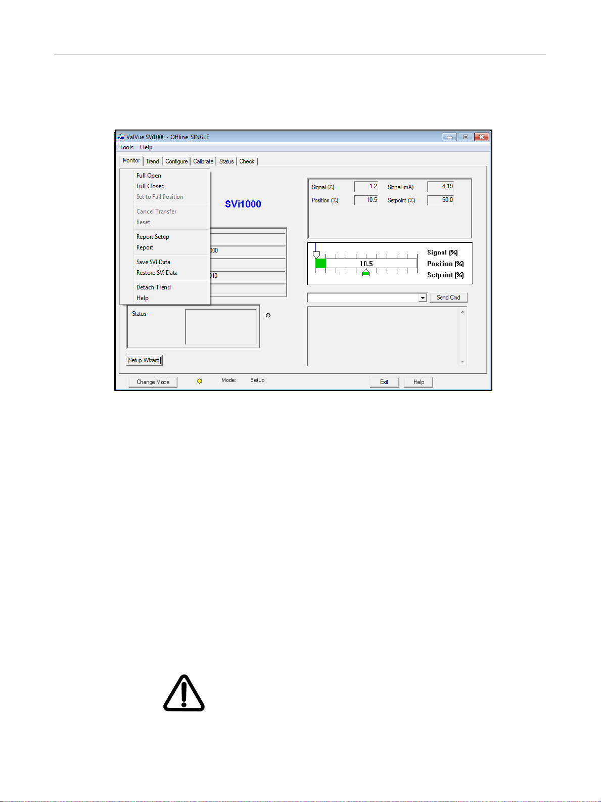
GE Oil & Gas
Monitor Context Menu
Right-click on the Monitor screen and a context menu appears (Figure 65).
ValVue Digital Communications Software Ver. 2.80
Figure 65 Monitor Screen Context Sensitive Menu
The following items appear and are greyed out based on the actual SVI II AP mode.
Full Open - Moves the valve to full open. This command takes the valve out of closed
loop control and sends a high or low signal to the I/P. This is available only in manual or
setup mode.
Full Closed - Moves the valve to full closed. This takes the valve out of closed loop
control and sends a high or low signal to the I/P. This is available only in manual or
setup mode.
Set to Fail Position - Sets the Output Pressure (P1) to 0 psig. Moves the valve full open or
full closed, whichever is the fail position of the actuator.
Cancel Transfer - Returns the SVI II AP to manual mode from the bumpless transfer
mode (available during a bumpless transfer).
Reset - Issues a master reset to the device, causing it to go through its startup routine
and re-initializing all of its operating parameters from non-volatile memory.
WARNING The valve moves during the reset operation.
90
Page 91

Restore SVI Data
Report Setup - Allows you to select a report setup set report template file and report
Report - Generates a report of the SVI II AP parameters
Save SVI Data - Saves the SVI II AP internal parameters in a file that can be read and
Restore SVI Data - Restores the contents of a dump file to a Masoneilan device. This
Backup NVM – Backups up the Non Volatile Memory (NVM). This is useful for factory
Detach Trend - Removes the Trend display from the anchored screen format and
Help - Displays the help file at the Monitor screen instructions.
Restore SVI Data
SVI II AP Monitor Screen
printing program
restored by ValVue.
can be used to clone an SVI II AP into a new SVI II AP. Items like tag, which must be
unique, and position calibrations which differ on each positioner are not cloned. This
command is available only in manual mode.
engineer to help troubleshoot an SVI II AP.
creates a separate trend display.
To restore SVI data:
1. Right-click and select Restore SVI Data and appears.
Figure 66 Restore SVI Data
2. Click OK and Figure 67 appears.
Figure 67 Time Warning
3. Click OK and an Open dialog appears.
4. Navigate to the dump file and click Open.
91
Page 92

GE Oil & Gas
Reports
One of the functions available on the Monitor screen is the ability to generate reports. ValVue
provides the ability to extract information about the SVI II AP operation and dump the
information into a report format. When ValVue extracts the information from a device it
requires a template file into which to dump the data. To generate a report with ValVue you
must first create a report template file that includes the parameters to include in the report as
well as personalization. There are three basic steps to create reports:
1. Set up the report - create a report template file
2. Select the report setup (report template file) - using the Report Setup command from the
3. Generate the report - using the Report command from the Monitor context menu.
Report Setup
1. Right-click on the Monitor screen and select Report Setup and Figure 68 appears.
ValVue Digital Communications Software Ver. 2.80
Monitor context menu.
Figure 68 Report Setup Dialog
2. Use the browser or type the path for the Report Template file name.
3. Select the program for report generation by clicking Auto Find or click the Browse button and manually locate the.exe.
Figure 69 Report Setup Completed
92
Page 93
Reports
Creating Report Template Files
You can create a custom SVI II AP report by creating a rich text format (RTF). The default
template is located in:
C:\ProgramData\Dresser\ValVue\SVI2 AP\Report\
Prior to selecting the set up of the report, you must create the report template file in an rtf
format. The report template should include the operation parameters that you would like
populated in the report.
ValVue substitutes the values of SVI II AP parameters into the text file where ever it finds a
parameter name that matches an SVI II AP parameter. For each parameter you would like
included in the report place $$ in front of the parameter name.
For example:
Tag = $$Tag
When creating the report template file, use an application that can save the report template
file to an rtf or text file such as WordPad or Microsoft Word.
SVI II AP Monitor Screen
NOTE rtf files are preferred as you can apply special formatting to the
file that can contain fonts, sizes, tabs, etc. and bitmaps. Some
.rtf formatting is accepted in Word which is not available in
WordPad.
The allowed SVI II AP parameters are listed in Table 5. Use the report file (report.rtf) shipped
with the application for examples.
Table 5 Report Setup Parameters
Report Parameter Information Provided in Report
$$Tag Tag Name
$$Descriptor Descriptor
$$Date Date
$$Message Message
$$AssemblyNumber Final Assembly Number
$$MfgID Manufacturer’s ID (101 for Masoneilan)
$$DeviceType Device Type (200 for the SVI II AP)
$$DeviceID Hart DeviceID
$$HWRev Hardware Revision
93
Page 94

GE Oil & Gas
ValVue Digital Communications Software Ver. 2.80
Table 5 Report Setup Parameters (Continued)
Report Parameter Information Provided in Report
$$SWRev Software Revision
$$CmdRev Firmware Command Revision
$$PollingAddress PollingAddress
$$Position Position
$$Signal Input Signal
$$Pressure Actuator Pressure
$$IPOutput Signal to the I/P in Counts (0 - 65000)
$$Temperature Circuit Board Temperature
$$LowTemperature Historical Low Temperature
$$HighTemperature Historical High Temperature
$$Output Output from the process controller
$$Mode SVI II AP Mode
$$SignalPercent Input Signal as Percent
$$AirAction Air-to-Open/Air-to-Close
$$ActuatorType Single/Double Acting Actuator
$$PosErrorBand Position Error Band
$$PosErrorTime Position Deviation Time
$$Charact Characterization (Linear, Equal Percentage, etc.)
$$CustomCharact Displays the Custom Characterization constants
Individual items of the characterization curve may be selected by entering:
$$CustomCharact[n] - where n is a number between 0 and 17
$$ButtonLock Button Lock Level
$$Bumpless Bumpless Transfer On/Off
$$BumplessSpeed Time to move from Manual to Normal (operating) mode
$$TightShutoff T ight Shutoff On/Off
$$TSValue Tight Shutoff Value
94
Page 95

Reports
Table 5 Report Setup Parameters (Continued)
Report Parameter Information Provided in Report
$$ULimitStop Upper Position Limit On/Off
$$ULSValue Upper Position Limit
$$LLimitStop Lower Position Limit On/Off
$$LLSValue Lower Position Limit
$$NearClosed Value below which is considered Near Closed
$$PosUnits Position Units of Measure (always %)
$$PresUnits Pressure Units (psi, bar, or kPa
$$SignalUnits Signal Units (always mA)
$$Language SVI II AP Display Language
$$LowSignal Low Calibration Value
SVI II AP Monitor Screen
$$HighSignal High Calibration Value
$$P Proportional Gain In Positioner
$$Padjust Adjustment to P when valve is exhausting
$$I Integral action of positioner
$$Beta Step size adjustment in positioner
$$D Derivative action of positioner
$$PosComp Position range compensation of positioner
$$DeadZone Dead zone of positioner
$$Damping Damping coefficient of positioner
$$Travel Total strokes of the valve
$$Cycles Total cycles of the valve
$$TimeOpen Total time open of the valve
$$TimeClosed Total time closed of the valve
$$TimeNearClosed Amount of time valve was nearly closed
$$ResponseOpen Time require to open valve
$$ResponseClosed Time required to close valve
$$Switch1Type Condition under which Switch 1 operates
95
Page 96

GE Oil & Gas
ValVue Digital Communications Software Ver. 2.80
Table 5 Report Setup Parameters (Continued)
Report Parameter Information Provided in Report
$$Switch1Value Value at which Switch 1 activates
$$Switch1Action Switch is Normally Closed or Normally Open
$$RawSignal Signal Value in A/D Counts
$$RawPosition Position Value in A/D Counts
$$PositionStopLow Position A/D Counts at the Lower Stop
$$PositionStopHigh Position A/D Counts at the Upper Stop
$$OptionConfig
$$OptionConfigEx0
$$OptionConfigEx1
$$OptionConfigEx2
$$OptionConfigEx3
Data describing the hardware installed on the positioner
$$Friction Friction Measured from a Standard Actuator Signature
$$FLowerSpringRange Lower Spring Range measured from a standard actuator signature
$$FupperSpringRange Upper Spring Range measured from a standard actuator signature
$$LowPressureActual Pressure when the actuator is exhausted
$$HighPressureActual Supply Pressure
$$Speed Speed at which the last diagnostic test was run
$$SpeedSaved Speed at which the saved standard signature was run
$$SpeedBaseline Speed at which the baseline standard signature was run
$$LowerSpringRange
$$LowerSpringRangeSaved
$$LowerSpringRangeBaseline
$$UpperSpringRange
$$UpperSpringRangeSaved
$$UpperSpringRangeBaseline
$$Signature Position/Pressure Pairs -gathered during the Standard Signature Test
Lower Spring Range calculated from the current, saved, or baseline standard signature
Upper Spring Range calculated from the current, saved, or baseline standard signature
$$SignatureSaved Position/Pressure Pairs - saved in the Saved Standard Signature
$$SignatureBaseline Position/Pressure Pairs- saved in the Baseline Standard Signature
96
Page 97

Reports
Smart Valve Interface 2AP - Configuration Data Sheet
General Information
Tag Name NEW
Descriptor
Date
Message
Assembly Number 0
Manufacturer’s ID 101
Device Type 206
Device ID 5010001
Hardware Revision 32
Transmitter Revision 1
Software Revision 1
Polling Address 0
Operating Data
Position 50.0 %
Signal 12.00 mA
Pressure 13.54 psi
Pressure2 0.00 psi
Supply Pressure N/A psi
Switch 1 Closed
Configuration Information
Air Action ATO
Actuator Type Single
Position Error Band 5.0 %
Position Error Time Off
Charactacterization Linear
Custom Charact.
In 100.0
Out 100.0
(Generate) Report
To generate a report:
ValVue populates the report template. An example of a report is shown in Figure 70.
SVI II AP Monitor Screen
Right-click and select Report.
Figure 70 Report Sample Using ValVue Template
97
Page 98

ValVue Digital Communications Software Ver. 2.80
This page intentionally left blank.
Page 99

Configure Screen
Ta g In formation
Language
Burst Settings
Characterization
Button Lock
Bumpless
Transfer
Air Action
Near Closed
Position Limits
Value
Configure I/O
What You Can Do on the Configure Screen
From the Configure screen, you can configure the valve/actuator by adjusting:
“Tag Information” on page 100 “Characterization” on page 102 “Button Lock” on page 107
3
“Air-to-Open / Air-to-Close” on
page 108
“Position Limit Stops” on page 108 “Position Fault Limits” on page 108 “Language” on page 108
“Burst Settings” on page 112 “Configure I/O” on page 109
“Bumpless Transfer” on page 107 “Near Closed” on page 107
Figure 71 Conf igure Screen - Setup Mode
99
Page 100

GE Oil & Gas
Tag Information
The Tag information contains an extra field, Polling Address. To change Tag information:
1. Enter data.
2. Click Apply.
Polling Address
The Polling Address doesn’t appear in the Tag information on the Monitor screen.
HART can communicate with up to 64 devices on a single pair of wires. These devices are
distinguished by their polling address which number from 0 to 63. If there is a device at polling
address 0, it must be the only device on the loop. There can be up to 63 devices with non-zero
polling addresses on the loop (subject to power and intrinsic safety constraints). For an SVI II
AP HART 6 device, polling address can be up to 63. Devices which operate 4-20 mA are
generally required to have polling address 0, however with split range valve positioners,
several 4-20 mA devices can be wired in series. Set these devices up with non-zero polling
addresses.
ValVue Digital Communications Software Ver. 2.80
NOTE ValVue must be in Setup mode to make any configuration changes
on this screen.
Table 6 Polling Address Applications
Positioner Application Polling Address Comment
Normal default on current loop 0 Use this for all single loop control.
Split range on a single current
loop
Split range with each positioner
on a current loop powered by isolator
Multidrop in voltage mode 1 to 63 Used with HART multiplexor. Follow
1 to 63 Give each device on the current loop a
unique address. 0 can cause errors. Use
the Options dialog to specify particular
addresses or an address range to save
scanning time.
1 to 63 Give each device operated by a single
controller a unique address. 0 can cause
errors. Use the Options dialog to specify
particular addresses or an address
range to save scanning time.
instructions of Mux manufacturer.
100
 Loading...