

GE Masoneilan 4700P, Masoneilan 4800P, Masoneilan 4800E, Masoneilan 4700E Maintenance Manual

GE Oil & Gas
Masoneilan*
4700P/4700E & 4800P/4800E
Pneumatic and Electropneumatic Positioners
Maintenance Manual (Rev. C)
GE Data Classification: Public

© 2015 General Electric Company. All rights reserved.
2 | =GE Oil & Gas
About this Guide
The information in this manual is subject to change without prior notice.
The information contained in this manual, in whole or part, shall not be transcribed or
copied without GE Oil & Gas’ written permission.
In no case does this manual guarantee the merchantability of the positioner or the
software or its adaptability to a specific client needs.
Please report any errors or questions about the information in this manual to your
local supplier or visit www.geoilandgas.com/valves.
Disclaimer
THESE INSTRUCTIONS PROVIDE THE CUSTOMER/OPERATOR WITH IMPORTANT
PROJECT-SPECIFIC REFERENCE INFORMATION IN ADDITION TO THE CUSTOMER/
OPERATOR'S NORMAL OPERATION AND MAINTENANCE PROCEDURES. SINCE
OPERATION AND MAINTENANCE PHILOSOPHIES VARY, GE (GENERAL ELECTRIC
COMPANY AND ITS SUBSIDIARIES AND AFFILIATES) DOES NOT ATTEMPT TO DICTATE
SPECIFIC PROCEDURES, BUT TO PROVIDE BASIC LIMITATIONS AND REQUIREMENTS
CREATED BY THE TYPE OF EQUIPMENT PROVIDED.
THESE INSTRUCTIONS ASSUME THAT OPERATORS ALREADY HAVE A GENERAL
UNDERSTANDING OF THE REQUIREMENTS FOR SAFE OPERATION OF MECHANICAL
AND ELECTRICAL EQUIPMENT IN POTENTIALLY HAZARDOUS ENVIRONMENTS.
THEREFORE, THESE INSTRUCTIONS SHOULD BE INTERPRETED AND APPLIED IN
CONJUNCTION WITH THE SAFETY RULES AND REGULATIONS APPLICABLE AT THE
SITE AND THE PARTICULAR REQUIREMENTS FOR OPERATION OF OTHER EQUIPMENT
AT THE SITE.
THESE INSTRUCTIONS DO NOT PURPORT TO COVER ALL DETAILS OR VARIATIONS IN
EQUIPMENT NOR TO PROVIDE FOR EVERY POSSIBLE CONTINGENCY TO BE MET IN
CONNECTION WITH INSTALLATION, OPERATION OR MAINTENANCE. SHOULD
FURTHER INFORMATION BE DESIRED OR SHOULD PARTICULAR PROBLEMS ARISE
WHICH ARE NOT COVERED SUFFICIENTLY FOR THE CUSTOMER/OPERATOR'S
PURPOSES THE MATTER SHOULD BE REFERRED TO GE.
THE RIGHTS, OBLIGATIONS AND LIABILITIES OF GE AND THE CUSTOMER/OPERATOR
ARE STRICTLY LIMITED TO THOSE EXPRESSLY PROVIDED IN THE CONTRACT
RELATING TO THE SUPPLY OF THE EQUIPMENT. NO ADDITIONAL REPRESENTATIONS
OR WARRANTIES BY GE REGARDING THE EQUIPMENT OR ITS USE ARE GIVEN OR
IMPLIED BY THE ISSUE OF THESE INSTRUCTIONS.
THESE INSTRUCTIONS ARE FURNISHED TO THE CUSTOMER/OPERATOR SOLELY TO
ASSIST IN THE INSTALLATION, TESTING, OPERATION, AND/OR MAINTENANCE OF
THE EQUIPMENT DESCRIBED. THIS DOCUMENT SHALL NOT BE REPRODUCED IN
WHOLE OR IN PART WITHOUT THE WRITTEN APPROVAL OF GE.

© 2015 General Electric Company. All rights reserved.
Masoneilan 4700P/E & 4800P/E Positioners Manual =| 3
Copyright
The complete design and manufacture is the intellectual property of GE Oil & Gas. All
information contained herein is believed to be accurate at the time of publication and
is subject to change without notice. All other trademarks and copyrights are
properties of their respective corporations.
Copyright 2015 by GE Oil & Gas. All rights reserved. PN 720014889-888- 0000 Rev. C
Document Changes
Version/Date Changes
B/08-2014 Added paragraph to first page of Calibration section about post-ship-
ment calibration.
C/04-2015 Added Disclaimer paragraph
and a new Figure 15.

This page intentionally left blank.

Masoneilan 4700P/E & 4800P/E Positioners Manual =| 5
© 2015 General Electric Company. All rights reserved
.
Safety Information .................................................................................... 11
Safety Symbols............................................................................................................................................. 11
4700P/4700E and 4800P/4800E Product Safety ......................................................................... 12
Introduction .............................................................................................. 15
General Description and Operation ................................................................................................... 15
Pilot ................................................................................................................................................................... 16
Direct Action ................................................................................................................................................. 16
Reverse Action ............................................................................................................................................. 16
Cam .................................................................................................................................................................. 16
Optional bypass valve (4700P, Direct Acting Model only) ........................................................ 16
Installation ................................................................................................ 19
Mounting and Orientation ..................................................................................................................... 19
Cover Removal............................................................................................................................................. 20
87/88 Actuator............................................................................................................................................. 22
Mounting 4700P and 4700E on Series 87/88 Actuators ......................................................... 24
87U/88U Actuator....................................................................................................................................... 26
Mounting 4700P/4800P and 4700E/4800E on Series 87U/88U Actuators ..................... 26
Positioner Mounting and Orientation ................................................................................................ 28
Camflex II, Varimax, MiniTork II, Ball II, and HPBV ....................................................................... 28
Pneumatic Installation.............................................................................................................................. 31
Electrical Installation of 4700E/4800E .............................................................................................. 34
Hazardous Area Installations................................................................................................................ 35
Factory Mutual Approved Version ..................................................................................................... 36
CSA (Canadian Standards Association) Approved Version ................................................... 37
SIRA Approved Version ............................................................................................................................ 38
Split Range Operation............................................................................................................................... 43
Mounting Cam Coupling.......................................................................................................................... 44
Mounting Cam ............................................................................................................................................. 44
Lever S/A Orientation ............................................................................................................................... 44
Changing Lever S/A Orientation ......................................................................................................... 45
Calibration ................................................................................................. 47
General ............................................................................................................................................................ 47
Zero Adjustment.......................................................................................................................................... 48
Span Adjustment......................................................................................................................................... 48
Cam Lobe Change...................................................................................................................................... 49
Air to Open / Direct Acting Positioner ............................................................................................... 49
Air to Open / Reverse Acting Positioner .......................................................................................... 49
Contents

© 2015 General Electric Company. All rights reserved.
6 | =GE Oil & Gas
Air to Close / Direct Acting Positioner ............................................................................................... 50
Air to Close / Reverse Acting Positioner ........................................................................................... 50
Field Mounting and Complete Calibration, Rotary Actuators................................................. 51
Air to Open / Direct Acting Positioner ...............................................................................................51
Air to Open / Reverse Acting Positioner ........................................................................................... 51
Air to Close / Direct Acting Positioner ............................................................................................... 52
Air to Close / Reverse Acting Positioner ........................................................................................... 53
Field Mounting and Complete Calibration Reciprocating Valves using 87/88 .............. 54
Air to Open / Direct Acting Positioner ...............................................................................................54
Air to Open / Reverse Acting Positioner (4700P/4800P only) .................................................54
Air to Close / Direct Acting Positioner ............................................................................................... 55
Air to Close/Reverse Acting Positioner (4700P/4800P only) ................................................... 56
Damping Adjustment ...............................................................................................................................56
Positioner Action Change (4700P/4800P Only) ............................................................................. 57
From Air to Open / Direct to Air to Open/Reverse ...................................................................... 57
From Air to Open / Reverse to Air to Open/Direct ......................................................................57
From Air to Close / Direct to Air to Close/Reverse ......................................................................57
From Air to Close / Reverse to Air to Close/Direct ...................................................................... 57
Maintenance.................................................................................................................................................. 58
Pilot .................................................................................................................................................................... 58
Disassembly .................................................................................................................................................. 58
Reassembly ................................................................................................................................................... 58
Body................................................................................................................................................................... 59
Disassembly .................................................................................................................................................. 59
Reassembly ................................................................................................................................................... 60
Diaphragm .................................................................................................................................................... 60
I/P Module ...................................................................................................................................................... 60
Bypass Valve Option (4700P Only).......................................................................................................61
Assembly to Positioner ............................................................................................................................ 61
Disassembly .................................................................................................................................................. 62
Troubleshooting........................................................................................................................................... 63
Split Range Operation - 4700P/4800P ..............................................................................................64
Cam Lobe Selection and Lever Arm Orientation.......................................................................... 65
Parts Reference 4700P/4800P 3-15 and 6-30 Range................................................................ 68
Parts Reference 4700E/4800E .............................................................................................................. 71
Parts Reference............................................................................................................................................ 73
Specification Data....................................................................................................................................... 75
Specifications ............................................................................................ 75
Drawings .................................................................................................... 77

Masoneilan 4700P/E & 4800P/E Positioners Manual =| 7
© 2015 General Electric Company. All rights reserved
.
Figures
1 Model 4700P/4700E and 4800P/4800E Positioner Numbering ..........15
2 Cover Removal............................................................................................................20
3 Rotary..............................................................................................................................21
4 Reciprocating .............................................................................................................21
5 87/88 Actuator............................................................................................................23
6 87/88 Actuator: Bracket Mounting Travel Settings....................................25
7 87U/88U Actuator .....................................................................................................27
8 Camflex II and Varimax...........................................................................................29
9 Ball II and MiniTork II.................................................................................................29
10 High Performance Butterfly Valve .....................................................................30
11 Pneumatic Installation.............................................................................................33
12 Electrical Connections .............................................................................................35
13 FM Installation.............................................................................................................40
14 CSA Installation...........................................................................................................41
15 ATEX Installation.........................................................................................................42
16 Split Range ....................................................................................................................43
17 Lobe Identification.....................................................................................................44
18 Pilot Subassembly......................................................................................................62
19 4700P/4800P 3-15 and 6-30 Ranges...............................................................68
20 4700E/4800E................................................................................................................71
21 Bypass Option (4700 Only).....................................................................................74
22 Positioner and Cast Body Assembly .................................................................77

This page intentionally left blank.

Masoneilan 4700P/E & 4800P/E Positioners Manual =| 9
© 2015 General Electric Company. All rights reserved
.
Tables
1 Mounting Parts Reference 87/88 .................................................................. 22
2 Mounting Parts Reference 87U/88U............................................................ 26
3 Mounting Parts Reference................................................................................ 28
4 Split Range Operation......................................................................................... 64
5 Parts Reference 4700P/4800P 3-15 and 6-30 Range ......................... 69
6 Parts Reference 4700E/4800E........................................................................ 72
7 Specification Data................................................................................................ 75

This page intentionally left blank.
Masoneilan 4700P/E & 4800P/E Positioners Manual =| 11
© 2015 General Electric Company. All rights reserved
.
This section provides safety information and defines the documentation safety symbols.
Read this entire section befor
e installation and operation.
Safety Symbols
4700/4800 instructions contain WARNINGS, CAUTIONS labels and Notes, where necessary, to
alert you to safety related or other important information. Total compliance with all WARNING,
and CAUTION notices is required for safe operation.
Indicates a potentially hazardous situation, which if not avoided
could result in serious injury or death.
CAUTION
WARNING
Safety Information

© 2015 General Electric Company. All rights reserved.
12 | =GE Oil & Gas
4700P/4700E and 4800P/4800E Product Safety
The 4700/4800 are intended for use with industrial compressed air or, natural gas systems only.
NOTE Installations using natural gas are Zone 0 or Div 1 installations.
Ensure that an adequate pressure relief provision is installed when the application of system
supply pressure could cause peripheral equipment to malfunction. Installation must be in accordance with local and national compressed air and instrumentation codes.
General installation, maintenance or replacement
Products must be installed in compliance with all local and national codes
and standards by qualified personnel using safe site work practices.
Personal Protective Equipment (PPE) must be used per safe site work
practices.
Ensure proper use of fall protection when working at heights, per safe site
work practices. Use appropriate safety equipment and practices to prevent
the dropping of tools or equipment during installation.
All surrounding pipe lines must be thoroughly flushed to ensure all entrained
debris has been removed from the system.
Indicates a situation, which if not avoided could result in property or data damage.
Indicates important facts and conditions.
CAUTION
NOTE
Masoneilan 4700P/E & 4800P/E Positioners Manual =| 13
© 2015 General Electric Company. All rights reserved
.
Hazardous Area Installation
Products certified as explosion proof or flame proof equipment or for use in intrinsically safe installations MUST BE:
Installed, put into service, used and maintained in compliance with national
and local regulations and in accordance with the recommendations
contained in the relevant standards concerning potentially explosive
atmospheres.
Used only in situations that comply with the certification conditions shown in
this document and after verification of their compatibility with the zone of
intended use and the permitted maximum ambient temperature.
Installed, put into service and maintained by qualified and competent
professionals who have undergone suitable training for instrumentation
used in areas with potentially explosive atmospheres.
WARNING Before using these products with fluids/compressed gases other
than air or for non-industrial applications, consult the factory or
local representative. This product is not intended for use in life
support systems.
WARNING Under certain operating conditions, the use of damaged
instruments could cause a degradation of the performance of the
system, which can lead to personal injury or death.
Installation in poorly ventilated confined areas, with any potential
of gases other than oxygen being present, can lead to a risk of
personnel asphyxiation.
Use only genuine replacement parts which are provided by the manufacturer, to guarantee that
the products comply with the essential safety requirements of the European Directives.
Changes to specifications, structure, and components used may not lead to the revision of this
manual unless such changes affect the function and performance of the product.

This page intentionally left blank.

Masoneilan 4700P/E & 4800P/E Positioners Manual =| 15
© 2015 General Electric Company. All rights reserved
.
General Description and Operation
The 4700P/4700E and 4800P/4800E positioners function to make a valve stroke proportional to
a pneumatic or electrical control signal from a controller, or to modify the natural flow characteristic of the valve itself through the use of a characterized cam. They can be configured to provide split-ranging of valves and may be used with supplemental air supplies to achieve greater
valve pressure drop. The 4700P/4800P pneumatic positioner can also be configured to reverse
valve response to a control signal (i.e. control signal can either open or close valve). The 4700E/
4800E electropneumatic positioner is not available with reverse action.
The Model 4700P/4700E and 4800P/4800E pneumatic positioner design is based on the
force-balance principle: the signal pressure exerted on a diaphragm is opposed by a feedback
spring. In the balanced state, when the pneumatic signal varies, the diaphragm assembly moves.
This movement is followed by the pilot plug which is opposed by the pilot spring.
Movement of the pilot plug alternately connects the output circuit to the supply circuit or the exhaust port, thus modifying air pressure to the actuator. The cam transmits valve plug movement
to the feedback spring. The valve plug continues to move until the spring force exactly balances
the force of the instrument signal on the diaphragm. In the new balanced state, the valve plug is
positioned in a programmed relationship to the instrument signal.
Figure 1 Model 4700P/4700E and 4800P/4800E Positioner Numbering System
Introduction

© 2015 General Electric Company. All rights reserved.
16 | =GE Oil & Gas
Pilot
The pilot is essentially a three-way sliding valve. The plug regulates supply air flow to and from
the actuator to the exhaust port. The position of this plug, governed by the diaphragm, determines the output pressure of the positioner. The 4700P/4800P pneumatic positioner action may
be reversed by interchanging the supply and exhaust connections and changing cam lobe and
lever arm orientation.
Direct Action
Increasing instrument signal pressure produces an increase in output pressure.
Reverse Action
Increasing instrument signal pressure produces a decrease in output pressure.
Cam
The cam is the intermediate element in the feedback mechanism between the actuator and the
feedback spring. Its profile determines the relationship between the valve plug position and the
control signal. Linear, Split Linear, or Percentage Control characteristics are available by selection
of proper lobe on cams supplied for Camflex II, Varimax, 87/88, and 87U/88U, actuators. Cams
supplied on Ball and Butterfly valves maintain the inherent valve characteristic. Custom characteristics are available on special order.
Optional bypass valve (4700P, Direct Acting Model only)
During normal operation, the instrument signal is applied directly to the positioner diaphragm
and the regulated supply pressure flows through the pilot valve to or from the actuator.
The bypass valve module permits the positioner to be isolated for maintenance while operating
the valve directly with the instrument signal. By turning the nylon bypass valve to the bypass position (the raised arrow on the bypass valve aligned with the word Bypass on the face positioner
body indicates this position), the normal positioner output pressure to the actuator is blocked
and the instrument signal is applied both to the positioner diaphragm and the actuator. The bypass valve does not block supply pressure to the pilot. Therefore, the supply line should be shut
off before disassembling the positioner.

Masoneilan 4700P/E & 4800P/E Positioners Manual =| 17
© 2015 General Electric Company. All rights reserved
.
WARNING When a valve (because of high pressure drop) uses a supply
pressure higher than 20 psig, the 3-15 psig instrument signal may
not be sufficient to operate the valve when the positioner is
bypassed. Moreover, if the positioner with a high supply pressure
is bypassed suddenly, the high pressure in the actuator may
damage the diaphragm and/or the control instrument. Therefore,
the bypass valve should be used only if the positioner supply
pressure is 20 psig (140 kPa or 1, 4 bar), or at most 35 psig (240
kPa, or 2, 4 bar), or if the controller is capable of operating the
valve directly. When bypassing a positioner, ensure that the
controller output is equal to supply required to operate valve.

This page intentionally left blank.

Masoneilan 4700P/E & 4800P/E Positioners Manual =| 19
© 2015 General Electric Company. All rights reserved
.
Mounting and Orientation
The valve is installed in the pipeline to operate in one of two ways:
Air to Open Air to Close
Close on air failure Open on air failure
(Reverse Action) (Direct Action)
The choice depends on the desired air failure action. This subject is dealt with in separate actuator instructions. The positioner can operate either by direct action (increasing instrument signal
produces an increase in output pressure) or reverse action (increasing instrument signal produces a decrease in output pressure). See Figure 3 and Figure 4.
The 4700E/4800E is not available w
ith reverse action, hence
if the application demands reverse action, a 4700P/4800P
with an external I/P Transducer is required.
NOTE
Installation

When installing a positioner on a valve, it is necessary to
choose the proper valve action and positioner action. It is
absolutely necessary to place valve travel at the point
corresponding to the low end of the signal range when
removing or installing a cam. At this point, feedback spring
compression is at lowest value and will facilitate cam
removal or installation. Prior to performing any work, read
and understand “General Description and Operation” on
page 15 and “Mounting and Orientation” on page 19. Define
the scope of work to be performed and find the appropriate
s
ection that should be followed.
© 2015 General Electric Company. All rights reserved.
20 | =GE Oil & Gas
The 4700 series positioners have the same mounting and link-age attachment dimensions as
the 4600, 4600A, 4600B and 4700B series positioners but have a different layout of pneumatic
connections. They can replace the older models if operational requirements are identical and
pneumatic connections are changed. The mounting details in this instruction cover only the
more widely used valves and actuators.
Cover Removal
The snap-on cover must be removed to access the zero and span adjustments and to mount the
positioner on the valve.
To remove the cover (Figure 2), press the latch bar inward as shown in the figure below, pull cover
away from body until latch tab is clear, then pull along body axis to free the two top locking tabs.
Figure 2 Cover Removal
CAUTION

Masoneilan 4700P/E & 4800P/E Positioners Manual =| 21
© 2015 General Electric Company. All rights reserved
.
Figure 3 Rotary
Figure 4 Reciprocating
For 4700P/4800P model only, positioner action can be reversed by simply engaging the proper
lobe on the cam and reversing the follower arm (numbers 1 and 2 above), and the supply and
exhaust ports (number 3 above).
* Option 4700P only

Table 1: Mounting Parts Reference 87/88
Ref.
No.
Description Ref.
No.
Description Ref.
No.
Description
100 Clamp Rod 110 Tubing 29 Screw,.312-18 x 1.25
101 Turnbuckle Screw 111 Positioner 30 Washer, Shakeproof
102 Clevis 112 Male Connector 37 Ring, Retaining
103 Back Lever 113 Cap Screw 38 Cap Screw
104 Clevis Pin 114 Lockwasher 39 Lockwasher
105 Retaining Clip 115 Mounting Bracket 40 Washer,.531 ID
106 Turnbuckle 122 Washer 41 Post Hub
107 Locknut 26 Cam 42 Input Shaft
108 Locknut 27 Washer 135 Instruction Plate
109 Elbow 28 Pan Head Screw
© 2015 General Electric Company. All rights reserved.
22 | =GE Oil & Gas
87/88 Actuator
Ref. Nos 109, 110, and 112 are not included in the mounting kit.
Masoneilan 4700P/E & 4800P/E Positioners Manual =| 23
© 2015 General Electric Company. All rights reserved
.
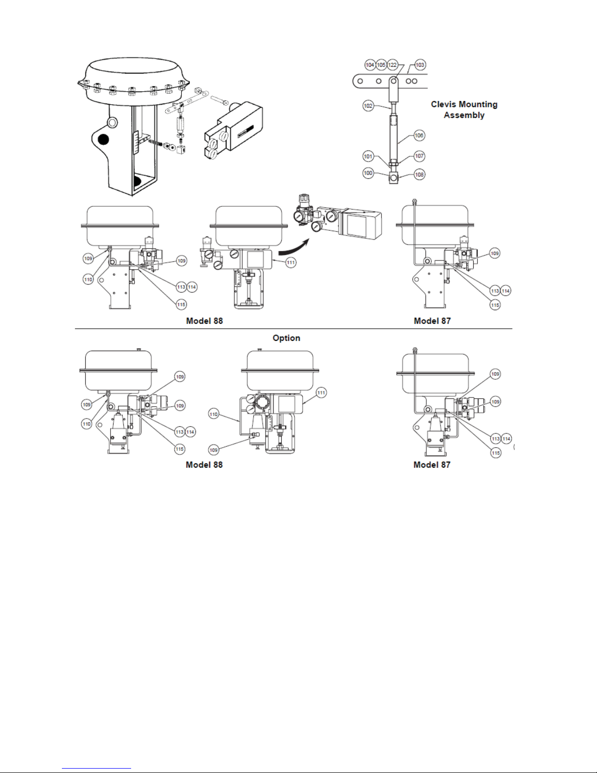
Figure 5 87/88 Actuator

© 2015 General Electric Company. All rights reserved.
24 | =GE Oil & Gas
Mounting 4700P and 4700E on Series 87/88 Actuators
1. Using screws (113) and lockwashers (114), mount bracket (115) on actuator with
opening located to the right side of the bracket (Figure 5).
2. Install input shaft (42) in post hub with a washer (40) on each side of the hub and
r
etaining ring (37) on cam end.
3. Mount back lever (103) to input shaft using screw (38) and lockwasher (39).
4. Install clevis (102), clevis pin (104), washer (122),
and retaining clip (105) in the
proper location on the back lever. Location is based on valve stroke required.
5. Check Figure 6 for proper mounting location for positioner on bracket.
6. Mount positioner on bracket using socket head screws (29) and lockwashers (30).
NOTE Back lever must be behind bracket.
7. Mount cam (26) on input shaft using washer (27) and screw (28) with desired lobe
ag
ainst cam follower. (Do not mount cam if positioner is reverse action).
8. Connect turnbuckle (106), locknut (107), turnbuckle screw (101), locknut (108), and
clamp r
od (100).
Model Travel (mm) Travel (in.) Hole Location
4700 20.3 .8 A
4700 25.4 1.0 B
4700/4800 38.1 1.5 C
4700/4800 50.8 2.0 D
4700/4800 63.5 2.5 E
NOTE Strokes shorter than 20.3 mm (0.8"), require a special mounting
kit. Consult with the factory for information.
 Loading...