

Page 1

GE Oil & Gas
Masoneilan* 12400 Series
Level Transmitter/Controller
Instruction Manual & Safety Guide
GE Data classification: Public
Page 2

Page 3

® 2014 General Electric Company. All rights reserved. Masoneilan 12400 Series Transmitter/Controller Instruction Manual | 1
THESE INSTRUCTIONS PROVIDE THE CUSTOMER/OPERATOR WITH IMPORTANT PROJECT-SPECIFIC
REFERENCE INFORMATION IN ADDITION TO THE CUSTOMER/OPERATOR’S NORMAL OPERATION
AND MAINTENANCE PROCEDURES. SINCE OPERATION AND MAINTENANCE PHILOSOPHIES VARY, GE
(GENERAL ELECTRIC COMPANY AND ITS SUBSIDIARIES AND AFFILIATES) DOES NOT ATTEMPT TO
DICTATE SPECIFIC PROCEDURES, BUT TO PROVIDE BASIC LIMITATIONS AND REQUIREMENTS
CREATED BY THE TYPE OF EQUIPMENT PROVIDED.
THESE INSTRUCTIONS ASSUME THAT OPERATORS ALREADY HAVE A GENERAL UNDERSTANDING OF
THE REQUIREMENTS FOR SAFE OPERATION OF MECHANICAL AND ELECTRICAL EQUIPMENT IN
POTENTIALLY HAZARDOUS ENVIRONMENTS. THEREFORE, THESE INSTRUCTIONS SHOULD BE
INTERPRETED AND APPLIED IN CONJUNCTION WITH THE SAFETY RULES AND REGULATIONS
APPLICABLE AT THE SITE AND THE PARTICULAR REQUIREMENTS FOR OPERATION OF OTHER
EQUIPMENT AT THE SITE.
THESE INSTRUCTIONS DO NOT PURPORT TO COVER ALL DETAILS OR VARIATIONS IN EQUIPMENT
NOR TO PROVIDE FOR EVERY POSSIBLE CONTINGENCY TO BE MET IN CONNECTION WITH
INSTALLATION, OPERATION OR MAINTENANCE. SHOULD FURTHER INFORMATION BE DESIRED OR
SHOULD PARTICULAR PROBLEMS ARISE WHICH ARE NOT COVERED SUFFICIENTLY FOR THE
CUSTOMER/OPERATOR'S PURPOSES THE MATTER SHOULD BE REFERRED TO GE.
THE RIGHTS, OBLIGATIONS AND LIABILITIES OF GE AND THE CUSTOMER/OPERATOR ARE STRICTLY
LIMITED TO THOSE EXPRESSLY PROVIDED IN THE CONTRACT RELATING TO THE SUPPLY OF THE
EQUIPMENT. NO ADDITIONAL REPRESENTATIONS OR WARRANTIES BY GE REGARDING THE
EQUIPMENT OR ITS USE ARE GIVEN OR IMPLIED BY THE ISSUE OF THESE INSTRUCTIONS.
THESE INSTRUCTIONS CONTAIN PROPRIETARY INFORMATION OF GE, AND ARE FURNISHED TO THE
CUSTOMER/OPERATOR SOLELY TO ASSIST IN THE INSTALLATION, TESTING, OPERATION, AND/OR
MAINTENANCE OF THE EQUIPMENT DESCRIBED. THIS DOCUMENT SHALL NOT BE REPRODUCED IN
WHOLE OR IN PART NOR SHALL ITS CONTENTS BE DISCLOSED TO ANY THIRD PARTY WITHOUT THE
WRITTEN APPROVAL OF GE.
Page 4

2 | GE Oil & Gas ® 2014 General Electric Company. All rights reserved.
Table of Contents
GENERAL ............................................................................................. 3
SPARE PARTS ............................................................................................. 3
AFTER SALES SUPPORT ............................................................................ 3
TRAINING ............................................................................................. 3
1. DESCRIPTION - OPERATION .............................................................. 4
1.1. P
RINCIPLE OF OPERATION ................................................................................ 4
1.2. SIGNAL PROCESSING .......................................................................................... 4
2. PROTECTION STANDARDS ................................................................ 5
2.1.
ATEX / IECEX CERTIFICATIONS ......................................................... 5
2.2.
FM / FMC CERTIFICATIONS ................................................................ 6
2.2.1. GENERAL REQUIREMENTS .............................................................................................. 6
2.2.2.
FLAMEPROOF AND DUST IGNITION PROOF REQUIREMENTS....................................... 6
2.2.3. I
NTRINSICALLY SAFE REQUIREMENTS ............................................................................ 6
2.2.4. D
ESCRIPTION OF EXPLOSION PROOF AND INTRINSIC SAFETY MARKING .................. 7
2.2.5. R
EPAIR................................................................................................................................ 8
2.2.6. ES-479
INTRINSICALLY SAFE INSTALLATION WIRING REQUIREMENTS .................... 9
2.2.7. N
OTES FOR INTRINSICALLY SAFE INSTALLATION........................................................10
3. MARKING – NUMBERING SYSTEM .................................................. 12
3.1. M
ARKING........................................................................................ 12
3.2. N
UMBERING SYSTEM ........................................................................ 12
4. INSTALLATION ................................................................................... 13
4.1. S
TORAGE AND CONDITIONS AT DELIVERY ........................................... 13
4.2. M
OUNTING ON SITE ......................................................................... 13
4.2.1. EXTERNAL MOUNTING ...................................................................................................13
4.2.2. I
NTERNAL MOUNTING ....................................................................................................14
5. CASE DESCRIPTION .......................................................................... 15
5.1. E
LECTRONIC COMPARTMENT ............................................................ 15
5.2. MECHANISM COMPARTMENT ............................................................ 15
5.3.
MTBF ............................................................................................ 15
5.4.
CONNECTION COMPARTMENT ........................................................... 15
5.4.1. ELECTRIC CIRCUIT ...........................................................................................................15
5.4.2. W
IRING AND CONNECTIONS ........................................................................................16
5.4.3. A
LLOWABLE SUPPLY VOLTAGES ...................................................................................16
5.4.4. M
AXIMUM POWER .........................................................................................................16
5.4.5. O
UTPUT SIGNAL AND LOAD RESISTANCE ...................................................................16
6. OPERATING THE INSTRUMENT ....................................................... 19
6.1. G
ENERAL PRINCIPLES ....................................................................... 19
6.1.1. THE LIQUID CRYSTAL DISPLAY (LCD) ...........................................................................19
6.1.2. P
USHBUTTONS ...............................................................................................................19
6.1.3. O
PERATING MODES ........................................................................................................19
6.1.4. P
USHBUTTONS MENUS DESCRIPTION .........................................................................20
7. COMMISSIONING .............................................................................. 22
7.1. INSTRUMENT COUPLING TO THE TORQUE TUBE ................................... 22
7.2. T
RANSMITTER CONFIGURATION ......................................................... 24
7.3. T
RANSMITTER CALIBRATION .............................................................. 25
7.3.3. CALIBRATION ON SITE WITH PROCESS FLUIDS .................................................30
7.3.4. C
ALIBRATION WITH MECHANICAL STOPS ........................................................31
7.4. CALIBRATION OF SPECIFIC GRAVITY METER ................................. 33
7.5. M
ECHANICAL STOPS SETTING .................................................... 34
7.6. T
ORQUE TUBE TEMPERATURE COMPENSATION ............................ 36
7.7. CONTROLLER FUNCTION (12410 MODEL ON LY) ......................... 38
8. SAFETY MANUAL FOR SIL APPLICATIONS ............................. 44
8.1. R
ELEVANT STANDARDS ............................................................. 44
8.2.
TERMS AND DEFINITIONS .......................................................... 44
8.3. SAFETY REQUIREMENTS ............................................................ 45
8.3.1. PROBABILITY OF FAILURES ON DEMAND (PFD) ..................................... 45
8.3.2. S
AFETY INTEGRITY OF THE HARDWARE ................................................. 45
8.4. SAFETY CHARACTERISTICS ......................................................... 45
8.4.1. ASSUMPTIONS .................................................................................. 45
8.4.2. S
AFETY INTEGRITY OF THE HARDWARE ................................................. 46
8.4.3. H
ARDWARE LOCK JUMPER ADJUSTMENT ............................................. 46
8.4.4. C
HARACTERISTICS ............................................................................. 47
8.5. SAFETY FUNCTION .................................................................... 47
8.6. P
ROOF TEST ............................................................................ 47
9. MAINTENANCE .......................................................................... 48
9.1. R
EMOVAL OF 12400 CASE FROM TORQUE TUBE ......................... 48
9.2. INSTALLATION OF 12400 CASE ON A TORQUE TUBE .................... 48
9.2.1. ON A 12200/300/400 SERIES TORQUE TUBE .................................. 48
9.2.2. ON
A 12120 OR 12800 SERIES TORQUE TUBE ................................... 49
9.3. REMOVAL OF 12400 CASE AND TORQUE TUBE S/A ...................... 50
9.4.
MOUNTING OF DLT CASE AND TORQUE TUBE S/A ......................... 51
9.5.
REVERSE INSTRUMENT CASE MOUNTING POSITION VERSUS TO
DISPLACER POSITION
(LEFT OR RIGHT) ........................................ 52
9.6. REPLACEMENT OF ELEC. AND MECH. COMPONENTS ..................... 52
10 TROUBLE SHOOTING ................................................................ 53
10.1. N
O SIGNAL ........................................................................... 53
10.2.
EXISTING SIGNAL BUT NOTHING ON LCD DISPLAY ...................... 53
10.3.
STEADY SIGNAL, NO CHANGE WHEN LEVEL VARIES ..................... 53
10.4.
OUTPUT SIGNAL DIFFERS FROM VALUE DISPLAYED ON LCD ........ 53
10.5. NO HART
®
COMMUNICATION ................................................ 54
10.6.
OUTPUT SIGNAL DOES NOT MATCH WITH THE LIQUID LEVEL
(LINEARITY ISSUE) .................................................................... 54
10.7. VIEW ERROR DIAGNOSTICS MESSAGES ...................................... 55
Appendix A
– NORMAL Menu / SETUP Menu ................... 60 to 61
Appendix B – BASIC SETUP Menu ...................................... 62 to 64
Appendix C – ADVANCED SETUP Menu ........................... 65 to 68
Appendix D – ENGINEERING UNIT Menu .......................... 69 to 71
Appendix E – 4-20mA GENERATOR Menu ........................ 72 to 73
Appendix F – VIEW DATA Menu ......................................... 74 to 75
Appendix G – FAILSAFE / VIEW ERROR Menus ................ 76 to 77
Page 5

® 2014 General Electric Company. All rights reserved. Masoneilan 12400 Series Transmitter/Controller Instruction Manual | 3
IMPORTANT: SAFETY WARNING
Read these instructions carefully BEFORE this instrument is installed or maintained.
Products certified for use in explosion proof (flameproof) or intrinsically safe installations MUST:
a) Be installed in accordance with EN/IEC 60079-14, EN/IEC 61241-14, EN/IEC 60079-17 standards and/or local and national codes for
hazardous area installations.
b) Only be used in situations which comply with the certification conditions stated in this manual and those stated in 400152322E ATEX
Instruction Manual.
c) Only be maintained by qualified personnel with adequate training on hazardous area instrumentation (see Instruction Manual
400152322E).
Taking the appropriate actions to ensure that site personnel who are performing installation, commissioning and
maintenance have been trained in proper site procedures for working with and around equipment, per Safe Site Work Practices,
are the end user's responsibility.
It is the end user's responsibility to:
• Verify material compatibility with the application
• Ensure proper use of fall protection when working at heights, per Safe Site Work Practices
• Ensure use of proper Personal Protective Equipment
• Take the appropriate actions to ensure that site personnel who are performing installation, commissioning and maintenance
have been trained in proper site procedures for working with and around equipment, per Safe Site Work Practices
Non-compliance with the rules and cautionary notes of this instruction may cause malfunction of the device or serious damage to it,
personnel or the surrounding equipment or site. Not intended for use in life support systems.
Items sold by GE are warranted to be free from defects in material and workmanship for a period of one year from the date of first use or
eighteen (18) months from the date of delivery, whichever occurs first, provided such items are used according to all relevant
recommendations and instructions from GE.
GE reserves the right to discontinue manufacture of any product or change product materials, design, or specifications without notice.
General
This manual provides installation, operation and maintenance instructions for the Masoneilan 12400 Series Digital Level
Transmitter/Controller from GE. It also includes a complete parts reference and a list of recommended spare parts.
Spare Parts
When performing maintenance, use GE’s Masoneilan spare parts only. Parts can be obtained through your local Masoneilan products
representative or the Spare Parts Department. When ordering parts, always include the Model and Serial Number of the unit being repaired.
After Market Support
GE offers aftermarket support for Masoneilan valves and instruments start-up, maintenance, and repair. Contact the nearest Masoneilan Sales
Office or Representative or After Sales Department.
Training
Regularly scheduled classes are conducted at GE’s Masoneilan facilities for training customer service and instrumentation personnel in the
operation, maintenance, and application of control valves and instruments. Arrangements for these classes can be made through your local
Masoneilan products sales contact.
Use of DANGER, WARNING, CAUTION, and NOTE.
These instructions contain DANGER, WARNING, CAUTION, and NOTE where necessary to alert you to safety
related or other important information.
DANGER - Hazards which result in severe personal injury or death.
WARNING - Hazards which could result in personal injury.
CAUTION - Hazards which could result in equipment or property damage.
NOTE - Alerts you to pertinent facts and conditions.
Although DANGER and WARNING hazards are related to personal injury, and the CAUTION hazards involve
equipment or property damage, it should be understood that operation of damaged equipment could, under
certain operational conditions, result in degraded process system performance which may lead to personal
injury or death. Therefore, comply fully with all DANGER, WARNING, and CAUTION notices.
Page 6

4 | GE Oil & Gas ® 2014 General Electric Company. All rights reserved.
1. Description - Operation
The 12400 Series Digital Level Transmitter/Controller is a high performance, easy-to-set instrument based on a modular design
that permits quick, low-cost upgrades as new features are developed and as your needs change.
1.1. PRINCIPLE OF OPERATION
The Masoneilan 12400 Series instrument from GE is a 2-wire, loop powered, digital displacement level transmitter/controller
with HART
®
communication that uses field proven buoyancy and torque tube principles.
A change in liquid level varies the apparent weight of the displacer (130), which increases or decreases load on the torque tube
(136) by an amount directly proportional to the change in liquid level. The resulting rotation of the torque rod (138), seen in
Figure 1, modifies the magnetic field of a frictionless, non-contacting sensor (40). The signal generated by the sensor varies
current in the loop in proportion to the level in the vessel.
1.2 SIGNAL PROCESSING
The sensor analog signal is converted into an error-free digital signal for processing by the on board micro-controller. After
signal processing, the digital result is converted to analog output signals for use by configuration and options.
Transmitter model:
♦ The 4-20 mA analog output signal, available on the AO_1 terminal, is the level or interface measurement signal with HART®
communication.
Transmitter model with two (2) adjustable switches and second 4-20mA analog output:
♦ The two 4-20 mA analog output signals, available on the AO_1 and AO_2 terminals, are the level or interface measurement signal, with
HART communication (AO_1 only).
♦ DO_1 and DO_2 terminals are two independent isolated digital switch outputs. They are user-adjustable and polarity sensitive.
Controller model with two (2) adjustable switches and second 4-20mA analog output:
♦ The 4-20 mA analog output signal, available on AO_1 terminals, is the controller output signal generated by a PID algorithm based on
error between the local setpoint and the level process variable. HART communication is available on AO_1.
♦
The 4-20 mA analog output signal, available on the AO_2 terminals, is the level or interface measurement signal. No HART
communication.
♦ DO_1 and DO_2 terminals are two independent isolated digital switch outputs. They are user-adjustable and polarity sensitive.
The 12400 instrument enables retrofit of existing pneumatic or digital level instruments (see Section 9.2).
PARTS REFERENCES
40
Non contact Sensor
135
Torque arm
55
Magnet
136
Torque tube
130
Displacer
137
Torque tube housing
131
Displacer chamber
138
Torque rod
Figure 1 – Diagram of principle
IMPORTANT
Options described above are operable only if they have been ordered initially. You cannot add them later on
site (see numbering system Section 3.2).
Page 7

® 2014 General Electric Company. All rights reserved. Masoneilan 12400 Series Transmitter/Controller Instruction Manual | 5
2. Protection standards
Installation in a hazardous atmosphere must be performed in accordance with the requirements specified in the applicable
standard for protection against explosion.
2.1. ATEX / IECEx CERTIFICATIONS
The 12400 Series Level Transmitter / Controller complies with the essential requirements of ATEX 94/9/EC European directive.
This instrument is certified for use in explosion proof (flameproof) or intrinsically safe installations with dust or gas from groups IIA, IIB and
IIC:
Category II 1 GD – zones 0, 1, 2, 20, 21 and 22 for protection mode "ia"
Category II 2 GD – zones 1, 2, 21 and 22 for protection mode "d".
The instrument also complies with the essential requirements of the modified EMC 2004/108/EC European directive for use
industrial environment.
It is the end user’s responsibility to ensure that products certified as explosion proof equipment or for use in intrinsically
safe installations MUST BE:
a) Installed, put into service, used and maintained in compliance with European and/or national and local regulations and
in accordance with the recommendations contained in the relevant standards concerning potentially explosive
atmospheres.
b) Used only in situations which comply with the certification conditions shown in this document and after verification of
their compatibility with the zone of intended use and the permitted maximum ambient temperature.
c) Installed and maintained only by personnel who have been trained and certified in installation, commissioning and
maintenance in proper site procedures for working with and around equipment, per Safe Site Work Practices.
Under certain operating conditions, use of a damaged instrument could cause a degradation of the performance of the
system, which may lead to personal injury or death, damage to the equipment and or other equipment, as well as the site.
Use only genuine replacement parts, provided by the manufacturer, to guarantee that the products comply with the
essential European Directives safety requirements mentioned above.
All actions related to installation, site commissioning and maintenance must be performed in accordance with
instructions provided in the ATEX instruction manual 400152322.
WARNING:
IMPROPER R
EPLACEMENT OR SUBSTITUTION OF ELECTRONIC COMPONENTS OR OF CERTAIN PARTS WHOSE
CHARACTERISTICS DO NOT MEET REQUIREMENTS OF THE APPLICABLE STANDARDS FOR EXPLOSION PROTECTION MAY
VOID THIS PROTECTION.
Page 8

6 | GE Oil & Gas ® 2014 General Electric Company. All rights reserved.
2.2. FM / FMc CERTIFICATIONS
2.2.1. GENERAL REQUIREMENTS
! WARNING !
Failure to adhere to the requirements listed in this
manual may cause loss of life and property.
Installation and maintenance must be performed only by qualified personnel. Area Classification, Protection Type, Temperature Class,
Gas Group, and Ingress protection must conform to the data indicated on the label.
Wiring and conduit must conform to all local and national codes governing the installation. Wiring must be rated for at least 5ºC above
the highest expected ambient temperature.
Approved wire seals against ingress of water and dust are required and the NPT fittings must be sealed with tape or thread sealant in
order to meet the highest level of ingress protection.
Where the protection type depends on wiring glands, the glands must be certified for the type of protection required.
The metal housing is in a standard die-casting alloy which is predominately aluminum. The housing can be stainless steel also.
Before powering the 12400:
1. Verify that the electronic cover screws are tightened. This maintains the ingress protection level and the integrity of the flameproof
enclosure.
2. If the Installation is Intrinsically Safe, check that the proper barriers are installed and the field wiring meets local and national codes for
an IS installation. Never install a device which was previously installed without an intrinsically safe barrier in an intrinsically safe system.
3. If the Installation is Non-Incendive, check that all the wiring meets local and national codes.
4. Verify that the markings on the label are consistent with the application.
2.2.2. FLAMEPROOF AND DUST IGNITION PROOF REQUIREMENTS
The ½” NPT fittings must enter the housing at least five full turns.
Conduit seals are required within 18” of the conduit for flameproof installation.
2.2.3. INTRINSICALLY SAFE REQUIREMENTS
Wiring must be in accordance with ES-749 (see Section 2.2.6) and must conform to national and local standards for intrinsically safe
installation.
Page 9

® 2014 General Electric Company. All rights reserved. Masoneilan 12400 Series Transmitter/Controller Instruction Manual | 7
2.2.4. D
ESCRIPTION OF EXPLOSION PROOF AND INTRINSIC SAFETY MARKING
The label may not appear exactly as shown, but must contain the information listed below. Additional information NOT pertaining to FM
approval is allowed on the label.
SERIAL
xxx
WARNING:
POTENTIAL DANGER OF
ELECTROSTATIC
DISCHARGE
Protection
PERMANENTLY MARK
PROTECTION TYPE.
ONCE MARKED, IT CAN NOT
BE CHANGED
Protection
Protection
AO_1 40V 23mA; AO_2 30V 23mA; DO_1 & DO_2 30V 1A
Dresser Inc Masoneilan Operations
DPI 14110 Conde-Sur-Noireau, France
SUPPLY CONNECTION WIRING RATED 5oC ABOVE AMBIENT
HOUSING CONDUIT ENTRY ½ INCH NPT
INGRESS PROTECTION TYPE 4X-6P
OPERATING TEMPERATURE LIMITS -40oC TO 80oC
Page 10
8 | GE Oil & Gas ® 2014 General Electric Company. All rights reserved.
2.2.5. REPAIR
WARNING: EXPLOSION HAZARD – SUBSTITUTION OF COMPONENTS MAY IMPAIR SUITABILITY FOR USE AND CAUSE DAMAGE TO
PERSONNEL, THE EQUIPMENT, OTHER EQUIPMENT AND THE SITE IN A HAZARDOUS LOCATION.
Only qualified service personnel are permitted to make repairs.
Replace ONLY with genuine Masoneilan parts from GE.
Only Masoneilan parts from GE are permitted. This includes not only the major assemblies but also mounting screws and “O” rings. No
substitutions with non-Masoneilan parts are permitted.
The following summary assures the safe operation of the 12400.
For ambient temperature greater than 70 °C, the user must choose a cable entry and a cable compatible with:
Ambient Temperature
Cable Temperature
75 °C
80 °C
80 °C
85 °C
The cable entry and the cable must be compatible with the minimum temperature of -40 °C as indicated on the marking plate.
The cable entry must have an ingress protection level at least equal to type 4X – 6P.
The joints (three pushbuttons, covers thread and O-ring) are greased with one of the following acceptable greases:
Grease Type
Manufacturer
GRAPHENE 702
ORAPI
MOLYKOTE111 COMPOUND
MOLYKOTE®
MULTILUB
MOLYKOTE®
GRIPCOTT NF
MOLYDAL
It is the user’s responsibility to check the gaskets once a year and in the event of damage to replace the defective parts with
manufacturer's replacement parts only.
For use in dusty hazardous areas, the user must maintain the enclosure to avoid the deposits of dusts, the maximum thickness must be
<5 mm. For safe operation, this can be done only if the local conditions around the device are free of potentially explosive atmosphere.
The user must check the temperature increase on the 12400 head coming from the mechanical part in contact with the 12400 housing or
through the process thermal radiation and ensure it is less or equal than the temperature classification allowed. This must be done in
conformance with EN/IEC 60079-14 and / or national and local regulations applicable for explosible atmospheres.
The user may clean the device, mainly the plastic label, with a wet rag to avoid any electrostatic spark. For safe operation, this can be
done only if the local conditions around the device are free of potentially explosive atmosphere.
Page 11

® 2014 General Electric Company. All rights reserved. Masoneilan 12400 Series Transmitter/Controller Instruction Manual | 9
2.2.6. ES-479
INTRINSICALLY SAFE INSTALLATION WIRING REQUIREMENTS
Each intrinsically safe cable must include a grounded shield or be run in a separate metal conduit.
3
1
2
4
VOLTAGE SUPPLY
FROM CONTROL SYSTEM
30V MAXI
1 to 5 Volts or 4-20mA
LEVEL FEEDBACK
to Control System
12400 LEVEL TRANSMITTER /
CONTROLER
PRIMARY OUT
4-20mA
SECONDARY OUT
4-20mA
SW1 / SW2
OUT
+
-
+
-
+
-
3
1
2
4
250 Ω
3
1
2
4
VOLTAGE SUPPLY
FROM CONTROL SYSTEM
30V MAXI
VOLTAGE SUPPLY
FROM CONTROL SYSTEM
30V MAXI
DI to CONTROL SYSTEM
OPTIONAL
SOLENOID
LOAD
1 to 5 Volts or 4-20mA
LEVEL FEEDBACK
to Control System
VALVE
POSITIONER
-
+
3
1
2
4
250 Ω
Note 7
Note 4
Note 6
Note 7
Note 7
Note 7
Note 5
Barrier with internal or external sense resistor.
Barrier with 4-20 mA retransmit.
See Note 3
Note 5
Note 6
Barrier with internal or external sense resistor.
See Note 4
Barrier type
See Note 5
Barrier type
See Note 6
4-20 mA SETPOINT
FROM CONTROL SYSTEM
With or
Without local
Solenoid
HAZARDOUS LOCATION
SEE NOTES 1 & 2
NON-HAZARDOUS LOCATION - UNSPECIFIED EXCEPT THAT
BARRIERS MUST NOT BE SUPPLIED FROM NOR CONTAIN
UNDER NORMAL OR ABNORMAL CONDITIONSA SOURCE OF
POTENTIAL WITH RESPECT TO EARTH IN EXCESS OF 250
VOLTS RMS OR 250 VOLTS DC.
The Optional 4-20 mA
secondary output from 12400
must not be connected in an
Intrinsic Safe Installation which
requires FM or CSA approval.
See Note4.
Page 12

10 | GE Oil & Gas ® 2014 General Electric Company. All rights reserved.
2.2.7. NOTES FOR INTRINSICALLY SAFE INSTALLATION
Note 1: HAZARDOUS LOCATION
Refer to the device label for the description of the environment in which the device may be installed.
For Div 1 areas the barriers are always required. For Div 2 areas the barriers are not required as long as Div 2 wiring practices
comply with the local electrical code and the supply voltages are normally less than 30 Volts.
Note 2: FIELD WIRING
Intrinsically Safe wiring must be made with grounded shielded cable or installed in grounded metal conduit. The electrical
circuit in the hazardous area must be capable of withstanding an A.C. test voltage of 500 Volts R.M.S. to earth or frame of the
apparatus for one minute. Installation must be in accordance with GE’s guidelines. The installation including the barrier
earthing requirements must comply with the installation requirements of the country of use.
Factory Mutual requirements (USA): ANSI/ISA RP12.6 (Installation of Intrinsically Safe Systems for Hazardous (Classified)
Locations) and the National Electrical Code, ANSI/NFPA 70. Division 2 installations must be installed per the National Electrical
Code, ANSI/NFPA 70. See also, note 4.
CSA requirements (Canada): Canadian Electrical Code Part 1. Division 2 installations must be installed per the Canadian
Electrical Code Division 2 Wiring Methods. See also note 4.
Note 3: PRIMARY OUT (+) and (-) 4-20 mA Terminals
These terminals are the main loop power of the 12400 and provide a 4 to 20mA signal related to the level measurement or the
embedded controller output for level control process. A transmitter type barrier with 250 Ohm series resistance (internal or
external) is used for this connection; for example, MTL 788 or 788R. For controller application, an active barrier with 4-20mA
retransmit can be used to drive a valve positioner.
Entity Parameters: Vmax= 30 VDC; Imax=125 mA; Ci=2 nF; Li=500 μH; Pmax=900 mW
Note 4: SECONDARY OUT (+) and (-) 4-20 mA Terminals
These terminals provide an additional 4 to 20 mA signal related to the level measurement. Use a transmitter type barrier with
250 Ohm series resistance (internal or external) for this connection; for example, MTL 788 or 788R.
Entity Parameters: Vmax=30 VDC; Imax=125 mA; Ci = 9 nF; Li=500 μH; Pmax=900 mW.
NOTE: The secondary out must not be connected in an Intrinsic Safe installation which requires FM or CSA approval.
Note 5: SW1 & 2 (+) and (-) Terminals
There are two independent isolated solid state switch contact outputs on the 12400. They are labelled SW#1 and SW#2. The
switches are polarity sensitive – that is, conventional current flows into the plus terminal. Examples of suitable barriers are MTL
707, MTL 787 and MTL 787S.
Entity parameters are: Vmax=30 VDC; Imax=125 mA; Ci = 4.5 nF; Li=10 μH; Pmax=900 mW.
Note 6: Controller mode
The barrier is a Controller Output Type; for example, MTL 728. This barrier can be driven by an active barrier with 4-20mA
retransmit or by the control system.
Entity Parameters: The optional device may be an I/P type 8000 series or a valve positioner type SVI II AP.
Note 7: Entity Requirement
Cable capacitance and inductance plus the I.S. apparatus unprotected capacitance (Ci) and inductance (Li) must not exceed
the allowed capacitance (Ca) and inductance (La) indicated on the associated apparatus. If the optional HART
®
handheld
Communicator (type DPI 620) is used on the Hazardous Area side of the barrier, then the capacity and inductance of the
communicator must be added and the communicator must be agency approved for use in the hazardous area. Also, the
current output of the Hand Held Communicator must be included in the current output of the associated equipment.
Page 13

® 2014 General Electric Company. All rights reserved. Masoneilan 12400 Series Transmitter/Controller Instruction Manual | 11
Note 8: Barrier type
The barriers may be active or passive and from any certified manufacturer for FMRC and CSA as long as the barriers comply
with the listed entity parameters.
Note 9: Use in dust atmosphere
Dust-tight conduit seal must be used when installed in dust hazard environments.
Note 10: Multiple protection approvals
A device which has previously been installed without an approved IS barrier must NEVER be used subsequently in an
intrinsically safe system. Installing the device without a barrier can permanently damage the safety related components in the
device making the device unsuitable for use in an intrinsically system.
Page 14

12 | GE Oil & Gas ® 2014 General Electric Company. All rights reserved.
3. Marking – Numbering System
3.1. MARKING
The firm plate (124) is applied on the top of the mechanical
compartment housing.
The following data are indicated: manufacturer contact details,
serial number, year of manufacturing and instrument electric
characteristics.
ATEX marking is described in 400152322 ATEX instruction
manual which is supplied with every 12400.
Figure 2 - Marking
3.2. NUMBERING SYSTEM
Note: only the Transmitter function is SIL certified.
12 4 a b
C d
Model Action Mounting Hazardous Protection Housing Material
4 – HART
®
communication protocol,
LCD display and pushbuttons, SIL Certified
1 – Controller with
adjustable switches
and second 4-20mA
analogue output
signal:
AO_1, AO_2,
DO_1, DO_2
2 – Transmitter: AO_1
3 – Transmitter with
adjustable switches
and second 4-20mA
analogue output
signal:
AO_1, AO_2,
DO_1, DO_2
0 – Top and bottom,
Screwed, BW or SW
1 – Top and bottom, Flanged
2 – Side and side, Flanged
3 – Top vessel, Flanged
4 – Side vessel, Flanged
5 – Top and side,
Screwed, BW or SW
6 – Side and bottom,
Screwed, BW or SW
7 – Side and bottom, Flanged
8 – Top and side, Flanged
9 – Side and side,
Screwed, BW or SW
1 – FM & FMc (ex CSA)
Intrinsically Safe,
Explosion proof, nL and
Nema 4X-6P
2 – JIS,
Explosion proof
3 – Rosteknadzor,
Intrinsically Safe,
Explosion proof, nL
and IP 66/67
4 – Inmetro,
Intrinsically Safe,
Explosion proof, nL
5 – ATEX & IECEx
Intrinsically Safe,
Explosion proof, nL
and IP 66/67
6 – Other approvals
(based on ATEX/IEC
approvals)
7 – Other approvals
(not based on
ATEX/IEC approvals)
1 – Aluminum with
epoxy painting
2 – 316L Stainless
steel
Page 15

® 2014 General Electric Company. All rights reserved. Masoneilan 12400 Series Transmitter/Controller Instruction Manual | 13
4. Installation
4.1. STORAGE AND CONDITION AT DELIVERY
Level instruments have been carefully packed in our premises to
prevent them from damage during handling and transportation.
Units must be stored in an area where temperatures are
between -50 °C and +93 °C.
Units are factory dry calibrated (simulation by weight) to the
service specific gravity specified by the customer.
When service specific gravity has not been specified, units are
factory dry calibrated to a specific gravity of 1.
Recalibration is recommended when the actual specific gravity
differs from calibration specific gravity.
Recalibration is needed when verification of instrument
performance is made with liquid in the displacer chamber.
4.2. MOUNTING ON SITE
Unpack the unit carefully and record the serial number for future
reference. Remove the shipping stud that secures the displacer in
the chamber.
Whenever possible, locate the instrument at some easily
accessible, well-lighted place on the vessel. The location must
have ambient temperature at the instrument case within the
range of -50 °C to +80 °C (unless limitations due to hazardous
area approvals – see Section 2).
NOTE: Do not remove instrument cover until the unit has been
installed and is ready for calibration.
The codes shown on numbering system indicate the instrument
designation as a function of various installation modes, displacer
chamber connections, and environmental standard or protection
of the case against explosion. Figures 3 and 6 show the various
ways of installing the displacer chamber.
4.2.1. EXTERNAL MOUNTING
(Chamber Type Model, Figures 3 & 4)
Install the instrument in a vertical position on the side of the tank
or vessel, so that the mid-range mark on the chamber is at
normal level. The mid-range is marked on the chamber.
The equalizing lines between chamber and vessel must be the
same size as the chamber connections. Install a block valve in
each line.
The use of a drain connection is recommended as shown in
Figure 3.
CAUTION: The displacer is always immobilized in the displacer
chamber to avoid any internal damage during transportation.
During the level installation, the displacer has to be unlocked by
unscrewing the M6 stern at the drain.
Type 12405 (Screwed NPT, BW, SW) Type 12406 (Screwed NPT, BW, SW)
Type 1240
8 (Flanged) Type 12407 (Flanged)
Figure 4
Type 12400 (Screwed NPT, BW, SW) Type 12409 (Screwed NPT, BW, SW)
Type 1240
1 (Flanged) Type 12402 (Flanged)
MID
RANGE
MID
RANGE
MID
RANGE
MID
RANGE
Page 16

14 | GE Oil & Gas ® 2014 General Electric Company. All rights reserved.
4.2.2. INTERNAL MOUNTING
An internally mounted 12400 Series instrument has no displacer chamber and the mechanism chamber bolts directly to the
vessel nozzle flange.
a. Type 12403 Top Flange Mounted Instrument (Figure 5)
There are two mounting possibilities:
1. Overhead space necessary for mounting the instrument is
sufficient:
♦ Attach the displacer to the torque tube before bolting the
chamber flange to the nozzle flange on the vessel.
2. Overhead space is insufficient: in this case, install a detachable
hanger extension. Before attaching the extension:
♦ Lower the displacer partway into the tank.
♦ Fasten and pin the extension to the displacer.
♦ Hook the displacer to the torque arm and lower the entire unit
into position. When the extension consists of several
detachable elements, repeat this operation for each element
and the lower the displacer progressively into the tank.
♦ Mount the instrument and bolt the mechanism chamber onto
the nozzle flange.
b. Type 12404 side flange mounted Instrument (Figure 6)
When the instrument is side flange mounted, provide enough clearance to permit attachment of the displacer after the
chamber flange is bolted in place. To attach the displacer:
♦ Reach into the end of the protective case and depress the torque arm.
♦ Bring the displacer hanger up through the hole in the bottom of the case and slip the displacer hanger over the
torque arm pin.
♦ Lower the displacer until the pin engages the top of the slot in the hanger.
4.2.2.1. Guide brackets for type 12404 (Figure 6)
If the liquid is in motion, provide brackets as shown in Figure 6 to guide the lower end of the displacer. The diameter of the
hole must be 25 to 35 mm (1” to 1 1/2”) larger than the diameter of the displacer for ranges to 1.8 m (6’), and 50 to 70 mm
(2” to 3”) larger for greater ranges.
Place the brackets at 50 to 70 mm (2” to 3”) from each end of the displacer. Locate the centerline of the hole so that the
displacer hangs freely.
4.2.2.2. Stilling well for type 12403 (Figure 5)
If the liquid is turbulent, provide a stilling well.
Make the well from tubing or pipe of a suitable diameter to allow
sufficient clearance between displacer and pipe. Mount it so that
it extends at least 75 mm (3”) below a free hanging displacer.
Provide a hole at the top of the stilling well to equalize pressure
between well and vessel.
4.2.2.3. Instrument case mounting (Figure 7)
The standard case mounting is left handed — the case is to the
left of the displacer. Right hand mounting is optional. To reverse
instrument case mounting, refer to Section 9 - Maintenance.
Figure 5 Figure 6
Type 12403 Type 12404
Left mounting
(top view)
Right mounting
(top view)
Figure 7
Page 17

® 2014 General Electric Company. All rights reserved. Masoneilan 12400 Series Transmitter/Controller Instruction Manual | 15
5. Case description
The purpose of this section is to describe the various instrument sub-assemblies to facilitate their use and maintenance.
See figures 8 to 13.
5.1. ELECTRONIC COMPARTMENT
The electronics compartment, located at the front of the instrument, can be accessed by removing the main cover (281). This
main cover is equipped with a glass (251) and three explosion proof pushbuttons (260).
The cover (281) is fully screwed on to the case (2) and sealed with an O-ring (109). It may be necessary to unscrew the cover
by less than a turn to align the window and LCD display and to install the safety screw (110). The cover (255) protects the
pushbuttons.
The sensor S/A (40) and its seal (111) are secured by two screws (112), located in the upper part of the electronics compartment.
The microprocessor, the display and the three pushbuttons are mounted on the resin potted electronic board which makes
the main electronic module (200). This subassembly is inserted into the case with the display facing the top of the case. It is
assembled by four screws (201).
5.2. MECHANISM COMPARTMENT
The mechanism compartment (Figures 12 & 13) on the back of the case has an opening on the right side (operator facing
instrument), which is closed by a threaded cover (107) and a gasket (108). A second opening at the bottom, closed by a
special 3/4” NPT plug (190), allows access to the mechanical flexure (59), which is part of the beam.
The mechanism (50) is completely factory assembled and calibrated before being installed into the mechanism
compartment. The pivot (51) is positioned toward the back of the case through two pins (52-53) and fastened by two screws
(113).
Two set screws (114) are located in tapped holes in the side of the case. The holes are covered by two plugs (115).
5.3. MTBF
The MTBF (Mean Time Between Failure) of 12400 Series instrument is 55.7 years, according to MIL-STD-HDBK-217F
Specification.
5.4. CONNECTION COMPARTMENT
Located on the left side, the connection compartment is closed by a threaded cover (104) with O-ring gasket (105) and locked
by a safety screw (106). It is equipped with a terminal board (90) mounted with a screw (92).
To mount the safety screw (106), the cover must be fully screwed on the case and then unscrewed by less than a turn.
5.4.1. ELECTRIC CIRCUIT
Both the terminal strip and the ground terminal are located in connection compartment (Figures 8 and 9). Connections are
done with four flat handle terminal blocks (90) or a terminal board connector (90A) (Japan) and included ground connection
(96). Follow strip rules to prevent from any short circuit and comply with local and national standards for hazardous area installations.
A 1/2” NPT (or M20) conduit connection is provided in the lower part of the junction box for connecting the supply leads via a
supplied stuffing box with an integrated cable clamp device or any cable gland with cable clamp device suitable for the
considered hazardous area.
DANGER:
FOR ANY ACTION ON 12400 SERIES INSTRUMENT, DO NOT REMOVE EITHER COVER PRIOR TO READING
400152322 ATEX INSTRUCTION MANUAL.
Page 18

16 | GE Oil & Gas ® 2014 General Electric Company. All rights reserved.
5.4.2.
WIRING AND CONNECTIONS
All wiring and connections must be done in accordance with EN/IEC 60079-14, EN/IEC 61241-14 and/or local and national codes
for hazardous area installations.
5.4.3.
ALLOWABLE SUPPLY VOLTAGES
Electrical connections on terminal board must respect polarity + and –, as well as maximum allowable supply voltages given
below. Connect the instrument to the ground using the ground terminals internally and externally to the case.
Supply Voltage
U (VDC)
AO_1 AO_2 DO_1/DO_2
MIN MAX MIN MAX MIN MAX
Explosion proof
10 V
40 V
10 V
30 V
0.5 V
30 V
Intrinsic Safety
10 V 30 V 10 V 30 V 0.5 V 30 V
5.4.4.
MAXIMUM POWER
3 W into 12400 case
5.4.5.
OUTPUT SIGNAL AND LOAD RESISTANCE
♦ AO_1 and AO_2
Response (scan) time: <60ms
Power interruption without causing reset: <100ms
Power-Up time: < 1s
Compliance with NAMUR NE-43 specification
standard level measurement: 3.8mA to 20.5mA
Low or high failsafe signals (severe fault): < 3.6mA or > 21mA
♦ Maximum load resistance
For AO_1 and AO_2: R max (Ω) = U (V) – 10 (V)
Imax (A)
♦ DO_1 and DO_2
There are two independent isolated output switches with open collectors. 1A maximum output signal. A load resistance must
be used in series to limit maximum current. 30 VDC across switch terminals and 1 A cannot exist simultaneously; doing so will
result in failure of the digital output circuit.
Figure 8 – Terminal board
Standard version with clamp (Ref. #90)
Figure 9 - Terminal board
Japanese version with screws (Ref. #90A)
R
load
U
Figure 10
Page 19

® 2014 General Electric Company. All rights reserved. Masoneilan 12400 Series Transmitter/Controller Instruction Manual | 17
Figure 11
Case External side view of case
Terminals for
local HART
®
communication
Figure 12
Front view
Cross-section back view
90 or 90A
90 or 90A
Page 20

18 | GE Oil & Gas ® 2014 General Electric Company. All rights reserved.
● Recommended spare parts ■ Spare parts available
1) These 3 rings are part of a kit.
PARTS REFERENCE
Ref N° Qty Parts Name Ref N° Qty Parts Name Ref N° Qty Parts Name
2
1
Case
■ 97
1
C M4-10 screw
■ 190
1
Plug S/A
40
1
Sensor S/A
■ 98
1
Lockwasher
191 1 Plug
50
1
Mechanism S/A
■ 99
1
Flat washer
192 1 Sponge cord
51
1
Pivot
■ 100
1
Clamp
200
1
Main electronic module
52
1
Pin
■ 101
1
C M5-12 screw
■ 201
4
CHC M4-25 screw
53
1
Special pin
■ 102
1
Lockwasher
241
1
Bias S/A
54
1
Beam
■ 103
1
Cap
242 1 Spring arm
55
1
Magnet
■ 104
1
Junction box cover
243 1 pin
56
2
“U” lamella
■ ●
1
O-ring (1)
244 2 Lateral screw
57
4
Flange, lamella
■ 106
1
CHC M4-16 screw
■ 281
1
Main cover S/A
58
8
CHC M4-8 screw
■ 107
1
Visit plug
280 1 Main cover
59
1
Flexible lamella
■ ●
1
O-ring (1)
250 1 Glass O-ring
60
2
CHC M3-8 screw
■ ●
1
O-ring (1)
251 1 Glass
62
1
CHC M3-8 screw
■ 110
1
CHC M4-16 screw
252 1 Clamp, spring
63
1
Flange, lamella
■ 111
1
O-ring, sensor housing
253 4 CHC M4x0.7x10 screw
270
1
Bell
■ 112
2
CHC M3-8 screw
■ 255
1
Cover, pushbuttons
271
1
HC M3-6 screw, bell
■ 113
2
CHC M4-20 screw
■ 256
1
Gasket cover, pushbuttons
70
1
Coupling lamella S/A
■ 114
2
Adjusting screw
■ 257
1
Screw captive panel
71
1
Coupling lamella
■ 115
2
1/8” NPT plug
■ 258
1
Pivot pin, pushbuttons cover
72
1
Pin
■ 75
1
Coupling S/A
■ 259
2
Circlip
73
1
Washer, coupling lamella
116
1
Coupling
260 3 Push Button
90
1
Standard terminal board S/A
117
1
Flange, coupling lamella
261 3 Spring compression
90A
1
Japan terminal board S/A
118
2
CHC M3-8 screw
262 3 Washer, retaining spring
■ 92
1
CHC M3-8 screw
■ 119
2
HC M3-6 screw
263 3 O-ring, pushbuttons
■ 93
1
Flat washer
■ ●
1
O-ring
264 3 Circlip
■ 94
1
Lockwasher
■ 121
4
CHC M6 screw
■ 290
1
Cable protector
■ 95
1
Flat washer
■ 122
4
Lockwasher
■ 291
1
Screw
■ 96
1
Clamp
124
1
Serial plate
Figure 13 – Cross Section of 12400 Series Digital Level Transmitter/Controller
Page 21

® 2014 General Electric Company. All rights reserved. Masoneilan 12400 Series Transmitter/Controller Instruction Manual | 19
6. Operating the instrument
6.1. GENERAL PRINCIPLES
All digital settings of the 12400 instrument are made by means of three pushbuttons and a liquid crystal display on the front
of the instrument, or using HART
communication handheld terminals or GE’s Masoneilan software: ValVue*, ValVue AMS*
Snap-on and ValVue PRM
*
. Instrument settings can also be performed with any software compliant with FDT/DTM protocol.
The codes or values displayed by the LCD can be seen through a window on the main cover. Access to the three pushbuttons
is obtained by opening the cover (255). It is not necessary to open the main cover for calibration or adjustment of the
instrument. Except for maintenance and out of hazardous area, the cover must remain closed.
6.1.1.
THE LIQUID CRYSTAL DISPLAY (LCD)
The LCD displays simultaneously two lines of nine ASCII characters and one line of seven digital characters.
The display is also used to configure, calibrate and diagnose the 12400 instrument.
For ease of operations, values, codes or short names appear on the display. The various parameters are listed in the menus
(see Appendixes A, B, C, D, E, F and G).
6.1.2.
PUSHBUTTONS
Three pushbuttons (260) are located behind the cover (255) on the front of the instrument.
♦ The left button is marked with a star , the middle button with the sign –, and the right one with the sign +.
♦ means enter the function, accept or save to memory. It may be understood as "YES".
♦ + or – means vertical movement in the program structure. It may be understood by "NO" or "NEXT" or "PREVIOUS".
NOTE:
♦ Do not over push on the buttons. Press a button at least one second to perform the action.
♦ Accidental pushing of any of the buttons will not cause any malfunction.
After using the buttons, check instrument is in back to NORMAL mode, which displays in sequence the current signal and the
level of liquid. Close the cover (255).
6.1.3. OPERATING MODES
The instrument can operate under three modes with associated menus:
♦ NORMAL Mode: It is the normal operating mode. As a level transmitter, the 4-20 mA output signal (AO_1) is proportional
to the level in the tank. As a level controller, the 4-20 mA output signal (AO_1) is the controller output. The local digital
display alternately displays loop current and level expressed in the unit (% or engineering unit) shown in the low left
corner of the screen. Reading of the instrument database is possible.
♦ SETUP Mode: Mode to set parameters of the instrument (configuration, calibration or diagnostic) or to read data. The
output current is not proportional to the tank level.
♦ FAILSAFE Mode: The instrument automatically sets to the failsafe mode when a severe error has occurred. The output
current is set to the value entered in the ADVANCED SETUP Menu.
Page 22

20 | GE Oil & Gas ® 2014 General Electric Company. All rights reserved.
6.1.4. PUSHBUTTONS MENUS DESCRIPTION AND HOW TO USE THEM
Seven Appendixes (A, B, C, D, E, F and G) detail the communication paths inside each menu and give descriptions and
explanations of each function.
♦ NORMAL Menu (see Appendix A).
♦ SETUP Menu (see Appendix A).
♦ BASIC SETUP Menu (see Appendix B).
♦ ADVANCED SETUP Menu (see Appendix C).
♦ ENGINEERING UNIT Menu (see Appendix D).
♦ FILTERING Menu (see Appendix D).
♦ 4-20mA GENERATION Menu (see Appendix E).
♦ AUTOMATIC TUNING Menu (see Appendix E).
♦ VIEW DATA Menu (see Appendix F).
♦ FAILSAFE Menu (see Appendix G).
♦ VIEW ERROR Menu (see Appendix G).
6.1.4.1. NORMAL Menu (Appendix A)
To enter NORMAL Menu from normal operating mode, press any button.
NORMAL menu allows to:
♦ Enter SETUP menu in order to set all instrument parameters.
♦ Access VIEW DATA menu (Appendix F) where the user can READ ONLY all current configuration, calibration and diagnostics
data saved in the instrument.
♦ View all faults which have occurred since the last fault clear with VIEW ERROR menu (Appendix G).
♦ Clear all faults with CLEAR FAULT function (Appendix G).
♦ Come back to normal operating mode: display in sequence of level variable and output current.
6.1.4.2. SETUP Menu (Appendix A)
SETUP menu allows to:
♦ Enter BASIC SETUP menu (Appendix B) to set all basic configuration and calibration parameters for a quick commissioning.
♦ Enter ADVANCED SETUP menu (Appendix C) to set all advanced configuration and calibration parameters for complete
management of process constraints and user practices.
♦ Come back to NORMAL menu.
♦ Access VIEW DATA menu (Appendix F) where the user can READ ONLY all current configuration, calibration and diagnostics
data saved in the instrument.
♦ View all faults which have occurred since the last fault clear with VIEW ERROR menu (Appendix G).
♦ Clear all faults with CLEAR FAULT function (Appendix G).
6.1.4.3. ENGINEERING UNIT Menu (Appendix D)
This menu allows the user to:
♦ Define the desired engineering unit for the level variable (%, cm, cm
3
…).
♦ Define the lower and higher level values (zero and span) expressed in engineering unit.
6.1.4.4. FILTERI
NG Menu (Appendix D)
This menu allows the setting of the two filterings available in the instrument:
♦ Damping adjustment (analog filtering).
♦ Smart filtering parameters tuning.
Page 23

® 2014 General Electric Company. All rights reserved. Masoneilan 12400 Series Transmitter/Controller Instruction Manual | 21
6.1.4.5. 4-20mA GENERATOR Menu (Appendix E)
This menu enables generation of a loop current to a defined value independently of true level measurement. This function is of
help to set another instrument (such a positioner) in series in the loop, by generating the required output current.
6.1.4.6. AUTOMATIC TUNING Menu (Appendix E)
This menu enables to automatic tuning of the smart filtering parameters.
6.1.4.7. FAILSAFE Menu (Appendix G)
This menu is available only when the instrument failed and went to FAILSAFE mode. Then, the output signal is locked in low or
high failsafe value (see Advanced Setup menu).
This menu allows the user to:
♦ Enter SETUP menu to change any parameter.
♦ Come back to normal operating mode: display in sequence of level variable and output current.
♦ Perform a reset of the instrument.
♦ Access VIEW DATA menu (Appendix F) where the user can READ ONLY all current configuration, calibration and diagnostics
data saved in the instrument.
♦ View all faults which have occurred since the last fault clear with VIEW ERROR menu (Appendix G).
♦ Clear all faults with CLEAR FAULT function (Appendix G).
Page 24
22 | GE Oil & Gas ® 2014 General Electric Company. All rights reserved.
7. Commissioning
This section is based on the following assumptions:
♦
12400 head has previously been mounted on a torque tube without coupling adjustment.
♦
Torque arm is mounted according to site requirements, if calibration has previously been done at workshop.
♦
Instrument is powered.
The steps described in the following pages for instrument settings and checking are done with the three pushbuttons and the
LCD display.
To perform 12400 commissioning through HART communication ValVue* software or handheld terminal, consult related
instruction manuals. Setting and calibration procedures are similar as based on the same philosophy.
Perform the following actions in the order given. They are also used for maintenance purposes. Several calibration procedures
are provided to cover available solutions at workshop and on site.
7.1. INSTRUMENT COUPLING TO THE TORQUE TUBE
NOTE: It is necessary to know the mounting direction (right or left) in order to correctly adjust the torque arm. See figures 7 and
23.
a. Remove the screw (106), the covers (104 & 107) of the connection and mechanism compartments, and the plug (190)
located at the bottom of the instrument.
b. Required level of liquid for coupling:
b1. At workshop with weights:
Coupling between torque tube and mechanism is achieved by simulating a half level of a 1.4 specific gravity liquid with
weights. Attach to the torque arm a weight equivalent to that of a displacer half immersed in a 1.4 specific gravity liquid
according to the following calculation:
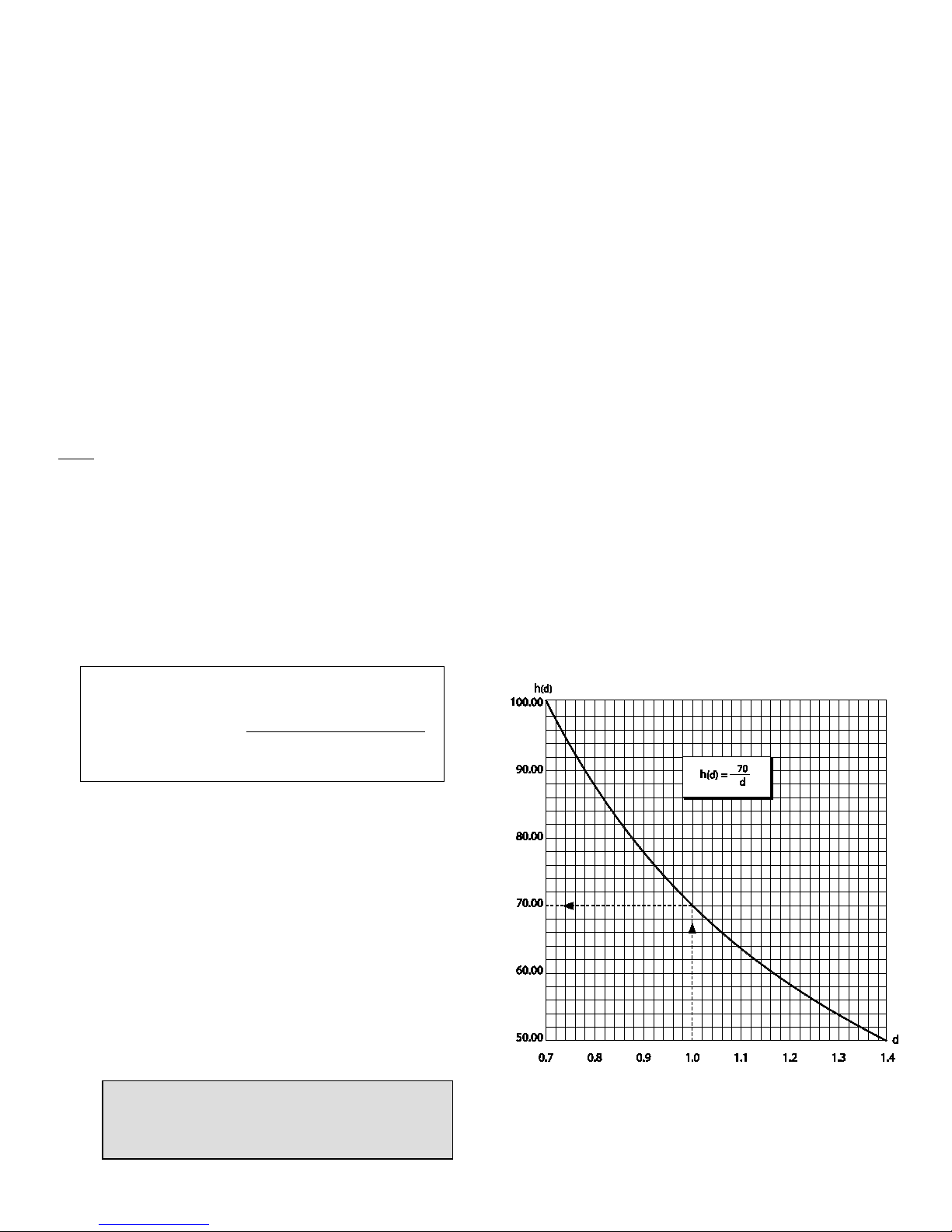
b2. On site with the process liquid(s):
Two situations may occur:
•
If the specific gravity (or the difference of the density in case
of an interface service) of the available liquid is between 0.7
and 1.4:
Simulate half level h (1.4) of a 1.4 specific gravity liquid with a
calculated value h (d) of the available liquid (refer to chart
Figure 14).
• If the specific gravity (d3) (or the difference of the density in
case of an interface service) of the available liquid is below
0.7:
Perform the coupling at high level in liquid service
(immersed displacer) or at high level of the highest spec
gravity liquid in interface application.
Figure 14
Curve of Half Level Simulation in a Liquid with S.G.
between 0.7 and 1.4
CAUTION: In this situation, the instrument must
be used for specific gravities (or the difference
of SG) ranging from 0.15 to 2xd3.
Simulated weight =
Actual displacer weight –
i.e. 1362 – 907 x 1.4 / 2 = 727.1 g for a standard displacer
(Actual volume displacer X 1.4)
2
Page 25

® 2014 General Electric Company. All rights reserved. Masoneilan 12400 Series Transmitter/Controller Instruction Manual | 23
c. Enter the BASIC SETUP menu to display [COUPLNG:%].
d. Look through the side orifice and verify that the screw (62) coupling end of the beam (54) is loose and that the spring arm
(242) is disengaged from the pin (243). Through the 3/4 ” NPT hole at the bottom of the case, push the flexure (59) from
left to right with your finger to verify it is possible to move the beam (54). The value displayed should vary accordingly. Pin
(72) must rotate freely inside the coupling end of the beam.
e. Look at the mechanism through the lateral orifice, and index the oval hole of the flexure towards the special conical
ended pin (53) by bending the flexure (59) toward the case front (see Figure 15). The value read on the LCD must be
between –5% and +5%.
NOTE: Check there is no oscillation of the weight used to simulate the displacer.
f. While holding the flexure (59) in that position, slightly but firmly tighten the screw (62) using a 2.5 mm Allen wrench.
g. Bias (spring arm function) setting
g1. Index again the flexure (59) on the conical ended pin (53).
g2. Move the spring arm (242) below the pin (243) on the beam. The pin has a groove to position correctly the spring.
Check the spring arm is locating inside the pin groove.
g3. Relax the flexible lamella, check the weight stability and control the value on the LCD is always inside +/-5%.
53
59
243
242
72
62
54
CAUTION:
Do not over tighten. This can damage the instrument.
Figure 15
Indexing for coupling adjustment
Page 26

24 | GE Oil & Gas ® 2014 General Electric Company. All rights reserved.
7.2. TRANSMITTER CONFIGURATION
Always perform or check instrument configuration before any calibration procedure. Configuration defines 12400 operating
mode, validates various features or sub-menus activation and impacts instrument internal diagnostics.
Check the following key features before initiating any calibration procedure:
♦ Measurement function: LEVEL or INTERFACE.
For special applications, it might be of interest to set the instrument in interface mode even for a level measurement. In this
case low specific gravity is set at 0.
♦ Mounting position of the instrument head versus displacer: LEFT or RIGHT.
An incorrect configuration causes calibration errors that my impact instrument operating and advanced diagnostics
capabilities.
♦ Loop current action: DIRECT or REVERSE.
This function both applies on AO_1 and AO_2 (main and second 4-20 mA output signals).
♦ See Appendixes A to G which describe operating and setting menus.
CAUTION:
In case of failsafe signal use ([FAIL LOW] or [FAIL HIGH]), check that loop current v
ariations are in line with
process and safety rules implemented into the Distributed Control System.
Page 27

® 2014 General Electric Company. All rights reserved. Masoneilan 12400 Series Transmitter/Controller Instruction Manual | 25
CAUTION: If a new calibration is performed, the
parameters of the reduced range [R SPAN:%] and/or zero
shift function [Z SHIFT:%] are automatically set to zero.
In interface service, if the [LSG SERV] and/or [HSG SERV]
are modified, an automatic calculation is performed to set
a new value in [Z SHIFT:%].
CAUTION: In interface service, if the [LSG SERV] and/or [HSG SERV] are modified, an automatic
calculation is performed to set a new value in [Z SHIFT:%].
7.3. TRANSMITTER CALIBRATION
7.3.1. OPERATING RULES AND CALIBRATION PRINCIPLE
The purpose of this chapter is to detail internal device operating rules to understand names of functions and describe actions
generated by the embedded firmware during calibration. Advanced settings are also described to answer user constraints. In
some cases, the user can avoid doing a new calibration following a process change or can enable a level measurement on a
specific range different than the standard one.
♦ Specific Gravity of Calibration:
Specific Gravity of Calibration is unique in level service and double in interface service. If Specific Gravity of Calibration is
unknown (enter 1.0 in level service, and 1.0 and 0.001 in interface service as default values) or known without accuracy,
calibration is still possible. However, automatic setting of the Specific Gravity of Service will not be correctly performed or may
generate measurement errors.
The Specific Gravity of Calibration is that of the liquid used (or simulated by weights) for zero and span calibration in the BASIC
SETUP menu. Modify it only if zero and span calibration are performed again for a liquid of different specific gravity. See Section
7.3.3.
♦ Specific Gravity of Service:
Specific Gravity of Service is unique in level service and double in interface service.
The Specific Gravity of Service is the one used for the function [SG SERV] in the BASIC SETUP menu. Its value is identical to that
of [SG CALIB] just after calibration. If the specific gravity of the process liquid is different, simply modify the value of [SG SERV]
without performing a new calibration.
♦ Reduced Span and/or zero shift:
For an application where the level change is smaller than
the displacer height, it is possible to obtain the full signal
range for this reduced level range thanks to Reduced Span
and Zero Shift functions.
Example: To modify a calibration so that 0 % corresponds to
a displacer immersed to 1/4 of its height (25%), and 100%
corresponds to a displacer immersed to 4/5 of its height
(80 %), adjust zero shift to 25 % and span reduction to 45 %.
See schematic on Figure 16.
[ZERO]: Corresponds to the low level reference; usually to the displacer not immersed in level application or to the displacer
fully immersed in lower specific gravity in an interface application.
[SPAN]: Corresponds to the high level reference; usually to the displacer fully immersed in level application or fully
immersed in higher specific gravity in an interface application.
Figure 16
Schematic example of reduced range
Page 28

26 | GE Oil & Gas ® 2014 General Electric Company. All rights reserved.
♦ Calibration of transmitter for level application:
The electronic circuit is calibrated towards two reference levels (REF L and REF H). See schematic below.
REF L corresponds to the displacer completely out of liquid.
REF H corresponds to the displacer fully immersed in the liquid of Specific Gravity used for calibration [SG CALIB].
The loop current corresponding to REF L may be set through [MA LO:mA] via [VAR SET]; it is generally 4mA.
The current corresponding to REF H may be set through [MA HI:mA] via [VAR SET]; it is generally 20mA.
The value of [MA HI:mA] must always be higher than the value of [MA LO:mA].
The level indication corresponding to REF L is set through function [LRV] via [VAR SET]; it is expressed in the unit set through
[UNIT] function; if UNIT is "%", [LRV] must be 0.00%.
The level indication corresponding to REF H is set through function [URV] via [VAR SET]; it is expressed in the unit set through
[UNIT] function; if UNIT is "%", [URV] must be 100.00%.
Page 29

® 2014 General Electric Company. All rights reserved. Masoneilan 12400 Series Transmitter/Controller Instruction Manual | 27
♦ Calibration of transmitter for interface application:
The level transmitter is used to measure the interface level of two immiscible liquids of different specific gravities. The displacer
must always be fully immersed.
The electronic circuit is calibrated towards two reference levels (REF L and REF H). See schematic below.
REF L corresponds to the displacer completely immersed in the liquid of Lower Specific Gravity used for calibration [LSG
CALIB].
REF H corresponds to the displacer fully immersed in the liquid of Higher Specific Gravity used for calibration [HSG CALIB].
The loop current corresponding to REF L may be set through [MA LO:mA] via [VAR SET]; it is generally 4mA.
The current corresponding to REF H may be set through [MA HI:mA] via [VAR SET]; it is generally 20mA.
The value of [MA HI:mA] must always be higher than the value of [MA LO:mA].
The level indication corresponding to REF L is set through function [LRV] via [VAR SET]; it is expressed in the unit set through
[UNIT] function; if UNIT is "%", [LRV] must be 0.00%.
The level indication corresponding to REF H is set through function [URV] via [VAR SET]; it is expressed in the unit set through
[UNIT] function; if UNIT is "%", [URV] must be 100.00%.
Page 30

28 | GE Oil & Gas ® 2014 General Electric Company. All rights reserved.
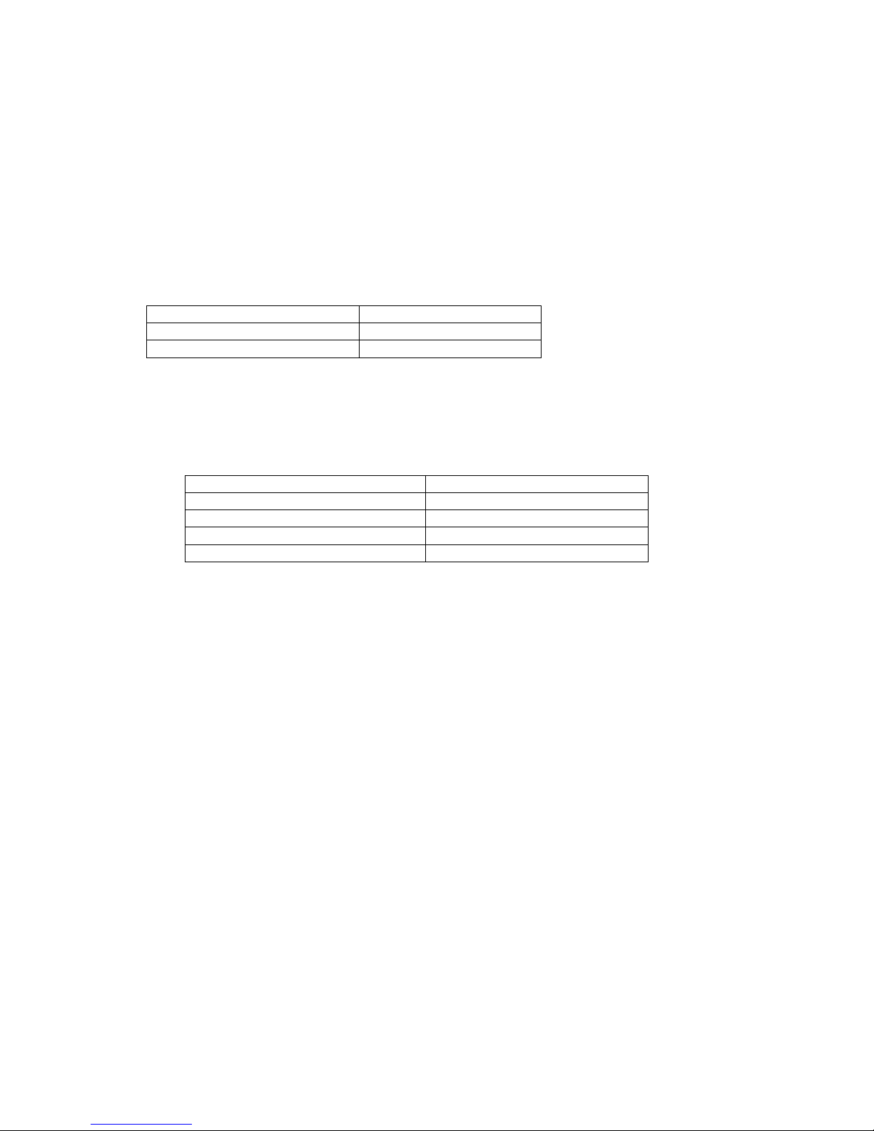
Standard displacer characteristics S.I Units English Units
Displacer weight 1362 g 3 lbs
Displacer volume 907 cm
3
55.34 in3
Fluid specific gravity
CAUTION: During the dry calibration without mechanism chamber, DO NOT ATTACH SPECIAL INTERFACE
DISPLACER (OR ITS EQUIVALENT EFFECTIVE WEIGHT) on the torque arm. Indeed, these displacers being
heavier than those for liquid level service and no mechanical stop being available without of mechanism
chamber, the torque tube and/or the instrument mechanism would be damaged.
7.3.2. CALIBRATION AT WORKSHOP WITH WEIGHTS
a. From [BAS SETUP] menu, enter the [CALIB Z S] sub-menu.
b. Enter specific gravity of calibration in level application [SG CALIB] or the low and high specific gravities in interface
application [LSG CALIB] and [HSG CALIB].
Actual volume and weight of the displacer can be read using HART communication (if data have been previously saved into
the 12400 instrument memory). Otherwise actual volume of the displacer is marked on the firm plate and displacer weight
can be measured by weighting of it.
c. Low Level [ZERO]
c1. Liquid application:
Attach to the torque arm a set of weights equivalent to the true displacer weight (i.e. 1362 g for a standard displacer) to
simulate the low level.
c2. Interface application:
Attach to the torque arm a set of weights equivalent to the displacer weight completely immersed in the liquid of Lower
Specific Gravity used for calibration [LSG CALIB] using the following formula:
c3. Enter and validate the [ZERO]: the [LEVEL:%] value indicated on the display must equal to 0.0%. If not, restart the
procedure until very close to this value. See Appendix B.
Displacer Apparent Weight for REF B =
Displacer Actual Weight - (Displacer Actual Volume X [LSG CALIB])
Page 31

® 2014 General Electric Company. All rights reserved. Masoneilan 12400 Series Transmitter/Controller Instruction Manual | 29
d. High Level [SPAN]
d1. Liquid application:
Attach to the torque arm a set of weights equivalent to the apparent weight of the displacer fully immersed in the
calibration fluid with Specific Gravity of Calibration [SG CALIB], i.e.:
d2. Interface application
Attach to the torque arm a set of weights equivalent to the displacer weight completely immersed in the liquid of
Higher Specific Gravity used for calibration [HSG CALIB] using the following formula:
d3. Enter and validate the [SPAN]: the [LEVEL:%] value indicated on the display must equal 100.0%. If not, restart the
procedure until very close to this value. See Appendix B.
e. Press the * button when [SAVE] is displayed to validate the [ZERO] and [SPAN] settings.
Displacer Apparent Weight for REF H =
Displacer Actual Weight - (Displacer Actual Volume X [SG CALIB])
i.e. 1362 – 907 x 1 = 455 g for a standard displacer and water
Displacer Apparent Weight for REF H =
Displacer Actual Weight - (Displacer Actual Volume X [HSG CALIB])
Page 32

30 | GE Oil & Gas ® 2014 General Electric Company. All rights reserved.
7.3.3. CALIBRATION ON SITE WITH PROCESS FLUIDS
a. From [BAS SETUP] menu, enter the [CALIB Z S] sub-menu.
b. Enter specific gravity of calibration for level application [SG CALIB] or the low and high specific gravities for interface
application [LSG CALIB] and [HSG CALIB].
c. Take all necessary actions to enable level variations into the displacer chamber: open/close isolation valves, vent, purge
…
d. Empty and fill the displacer chamber with fluid(s) of service to get level variations.
e. Wait for a few seconds until the displacer stabilizes to validate and save the values displayed on the LCD after each level
variation.
f. Low Level [ZERO]
f1. Liquid application:
Empty the displacer chamber.
f2. Interface application:
Fully immerse the displacer in the liquid of Lower Specific Gravity used for calibration [LSG CALIB].
f3. Enter and validate the [ZERO]: the [LEVEL:%] value indicated on the display must equal to 0.0%. If not, restart the
procedure until very close to this value. See Appendix B.
g. High Level [SPAN]
g1. Liquid application:
Fully immerse the displacer in the liquid of Specific Gravity used for calibration [SG CALIB].
g2. Interface application:
Fully immerse the displacer in the liquid of Higher Specific Gravity used for calibration [HSG CALIB].
g3. Enter and validate the [SPAN]: the [LEVEL:%] value indicated on the display must be equal 100.0%. If not, restart the
procedure until very close to this value. See Appendix B
h. Press the * button when [SAVE] is displayed to validate the [ZERO] and [SPAN] settings.
Page 33

® 2014 General Electric Company. All rights reserved. Masoneilan 12400 Series Transmitter/Controller Instruction Manual | 31
7.3.4. CALIBRATION WITH MECHANICAL STOPS
This calibration procedure is very useful on site and for interface application when there is no capability to make level
variations into the tank.
a. Open the access plug (107) on the right side of the case to look at the simulation mechanism. Remove plug (190) and the
two 1/8” NPT plugs (115). Use a 5 mm Hex wrench.
b. Simulate level variations by moving the flexure (59) in the direction of the torque tube until the flexure touches the
adjusting screw post (114).
c. While maintaining contact, slide the flexure left or right along the surface of the screw post (figure 17) to simulate low and
high level values of the process fluid(s).
d. Enter [BAS SETUP] menu and the [CALIB Z S] sub-menu.
e. Enter specific gravity of calibration in level application [SG CALIB] or the low and high specific gravities in interface
application [LSG CALIB] and [HSG CALIB].
f. Low Level [ZERO]
f1. Liquid application:
Move the flexure (59) against the adjusting screw shoulder (114), which corresponds to the low level (opposite side to
the displacer). Wait for a few seconds until the displacer stabilizes.
f2. Interface application:
Move the flexure (59) against the adjusting screw shoulder (114), which corresponds to the lowest specific gravity fluid
of calibration [LSG CALIB] (opposite side to the displacer). Wait for a few seconds until the displacer stabilizes.
f3. Enter and validate the [ZERO]: the [LEVEL:%] value indicated on the display must equal 0.0%. If not, restart the
procedure until very close to this value. See Appendix B.
CAUTION:
This procedure is only possible if mechanical stops (adjusting screws) have been previosuly adjusted upon process fluids.
See mechanical stops setting Section 7.5.
Figure 17
Calibration with adjusting screws
Page 34

32 | GE Oil & Gas ® 2014 General Electric Company. All rights reserved.
g. High Level [SPAN]
g1. Liquid application:
Move the flexure (59) against the adjusting screw shoulder (114), which corresponds to the high level of calibration
fluid [SG CALIB] (on displacer side). Wait for a few seconds until the displacer stabilizes.
g2. Interface application:
Move the flexure (59) against the adjusting screw shoulder (114), which corresponds to the high level of highest specific
gravity fluid of calibration [HSG CALIB] (on displacer side). Wait for a few seconds until the displacer stabilizes.
g3. Enter and validate the [SPAN]: the [LEVEL:%] value indicated on the display must equal 100.0%. If not, restart the
procedure until very close to this value. See Appendix B.
h. Press the * button when [SAVE] is displayed to validate the [ZERO] and [SPAN] settings.
i. Reinstall all plugs (107), (190), and (115).
Page 35

® 2014 General Electric Company. All rights reserved. Masoneilan 12400 Series Transmitter/Controller Instruction Manual | 33
Parameter name S.I Units English Units
Displacer weight g lbs
Displacer volume cm
3
in3
Fluid specific gravity
7.4. CALIBRATION OF SPECIFIC GRAVITY METER
This adjustment is made at the factory for complete instruments. The specific gravity function [SG METER] is very useful in
performing on site new calibrations, simulations with or without liquid and direct reading of specific gravity of liquids on the
application.
CAUTION:
The Specific Gravity Meter function is factory calibrated at a specific gravity of 1.0 for a complete instrument only if the
displacer volume is lower than 1270 cm3 and the weight is 1362 g.
For an instrument delivered alone with a torque tube, the Specific Gravity Meter function is factory calibrated at a S.G.
1.0 for a displacer with 907 cm3 volume and 1362 g weight.
If actual displacer characteristics differ from these values, recalibration is required and is possible only if displacer
volume is lower than 1270 cm3 and if service specific gravity x displacer volume is lower than 1270.
Reading of the specific gravity of a liquid is possible only when displacer is fully immersed into the liquid and if [SG
METER] function has been previously calibrated.
a. Into the [ADV SETUP] menu, enter the [SGM CALIB] sub-menu. See Appendix C.
b. Enter the Specific Gravity of Calibration of the S.G. Meter [SG CALIB] =1.0
c. L
OW LEVEL [ZERO]
c1. Attach a set of weights to the torque arm equivalent to the true displacer weight (i.e. 1362 g for a standard displacer) to
simulate the low level or empty the displacer chamber.
c2. Enter and validate the [ZERO]: the [LEVEL:%] value indicated on the display must equal 0.0%. If not, restart the
procedure until very close to this value. See Appendix C.
d. H
IGH LEVEL [SPAN]
d1. Attach a set of weights to the torque arm equivalent to the apparent displacer weight in high level position with
Specific Gravity of Calibration [SG CALIB] 1.0 or fill the displacer chamber up to the high level position. Stabilise the
displacer (or weights).
Actual volume and weight of the displacer can be read using HART communication (if data have been previously saved into
the 12400 instrument memory). Otherwise actual volume of the displacer is marked on the firm plate and displacer weight
can be measured by weighting of it.
d2. Enter and validate the [SPAN]: the [LEVEL:%] value indicated on the display must equal 100.0%. If not, restart the
procedure until very close to this value. See Appendix C.
e. Press the * button when [SAVE] is displayed to validate the [ZERO] and [SPAN] settings.
f. To check if the specific gravity meter calibration has been correctly done, go to VIEW DATA menu, then [SG METER] to read
values corresponding to low and high references.
Displacer Apparent Weight for REF H=
Displacer Actual Weight - (Displacer Actual Volume X [SG CALIB])
i.e. 1362 – 907 x 1 = 455 g for a standard displacer and water
Page 36

34 | GE Oil & Gas ® 2014 General Electric Company. All rights reserved.
7.5. MECHANICAL STOPS SETTING
This procedure consists of setting the mechanical stops (adjusting screws) on the specific gravities of the process. Then, these
adjusting screws are very helpful to perform a dry calibration (without fluid).
The two adjusting screws (114) are located on the sides of the case and are closed by two 1/8” NPT plugs (115). They are
adjusted at factory if the specific gravity meter has been calibrated upon displacer type used.
a. Open the access plug (107) on the right side of the case to look at the simulation mechanism. Remove plug (190) and the
two 1/8” NPT plugs (115). Use a 5 mm hex wrench.
b. Through this hole, to define REF L and REF H, use your finger to move the flexure (59) in the direction of the torque tube
until the flexure touches the adjusting screw post (114). While maintaining contact, slide the flexure left or right along the
surface of the screw post (Figure 18).
c. Perform the two adjusting screws (114) setting by reading the specific gravity value indicated by the specific gravity meter
through VIEW DATA menu and SPECIFIC GRAVITY METER sub-menu.
d. Enter VIEW DATA menu and SPECIFIC GRAVITY METER sub-menu.
e. L
OW LEVEL REFERENCE [ZERO]
e1. Liquid application:
Press the flexure (59) against the adjusting screw shoulder (114), which corresponds to the low level (opposite side to
the displacer). While maintaining contact and using a 3 mm hex wrench, turn the adjusting screw until LCD displays
the specific gravity value 0.0.
e2. Interface application:
Press the flexure (59) against the adjusting screw shoulder (114), which corresponds to the lowest specific gravity
[LSG CALIB]. While maintaining contact and using a 3 mm hex wrench, turn the adjusting screw until LCD displays
this specific gravity.
CAUTION:
This procedure is only possible if the [SG METER] function has been calibrated.
Figure18
Setting of adjusting screws
CAUTION:
Specific gravity value refresh requires exiting and entering again the SPECIFIC GRAVITY METER sub-menu.
Page 37

® 2014 General Electric Company. All rights reserved. Masoneilan 12400 Series Transmitter/Controller Instruction Manual | 35
f. HIGH LEVEL REFERENCE [SPAN]
f1. Liquid application:
Press the flexure (59) against the adjusting screw shoulder (114) which corresponds to the high level (on displacer
side). While maintaining contact and using a 3 mm hex wrench, turn the adjusting screw until LCD displays the value
of process specific gravity [SG CALIB].
f2. Interface application:
Press the flexure (59) against the adjusting screw shoulder (114) which corresponds to the highest specific gravity
[HSG CALIB]. While maintaining contact and using a 3 mm hex wrench, turn the adjusting screw until LCD displays
this specific gravity.
g. Slowly move the flexure (59) from one shoulder (114) to the other (slowly to avoid displacer oscillations) and verify the value
displayed. Correct adjustments if necessary.
h. Reinstall all plugs (107), (190), and (115).
Page 38

36 | GE Oil & Gas ® 2014 General Electric Company. All rights reserved.
7.6. TORQUE TUBE TEMPERATURE COMPENSATION
7.6.1. GLOBAL PURPOSE
The 12400 Series instrument includes a non-intrusive and integrated software temperature compensation of the torque tube
from -210°C to +450°C.
There are two temperature sensors located in the sensor board and the main circuit board of the instrument.
Variation of torque tube Young modules over ambient and process temperatures shall be compensated to prevent any zero
shift and span variation on very high or low process temperature applications.
The software module compensates these potential variations of Young modules that may happen in case of temperature
difference between temperature saved during calibration procedure and current temperature (impacted by ambient and
process temperatures).
This function is available on device revision Firmware 114 or later.
ValVue suite software is required to set this temperature compensation feature. Push-buttons and any HART handheld do not
enable to activate and set this feature.
7.6.1. TEMPERATURE COMPENSATION ACTIVATION
Through ValVue suite software, the temperature compensation feature is enabled or disabled on the Advanced Setup menu.
a. Change device mode to Advance Setup and go on the Advanced Setup tab.
b. Activate the Torque Tube temperature compensation by clicking TT Activation checkbox.
c. To define the expected process temperature, click the Process Temperature checkbox and enter the corresponding
temperature value in degC.
d. Validate by clicking on Apply.
Page 39

® 2014 General Electric Company. All rights reserved. Masoneilan 12400 Series Transmitter/Controller Instruction Manual | 37
7.6.2. T
EMPERATURE COMPENSATION SETTING
Through ValVue suite software, the temperature compensation parameters can be set on the Advanced Setup menu.
a. On the Advanced Setup tab, click on Database.
b. Click on the arrow of the drop down list, located at the right of the Torque Tube Matl.
c. Select the materials related to the torque tube and housing sub-assembly: Inconel/Carbon Steel, Inconel/St. Steel, St.
Steel/St. St., Monel/Carbon Steel, etc.
In case of No Torque Tube setting, Inconel/Carbon Steel temperature compensation is applied by default.
e. Validate by clicking on Apply.
Page 40

38 | GE Oil & Gas ® 2014 General Electric Company. All rights reserved.
7.7. CONTROLLER FUNCTION (12410 MODEL ONLY)
The 12410 model Level Controller is a Level measurement instrument which includes a built-in PID controller function to
directly and locally control a level control loop. It has been specifically designed to retrofit pneumatic level control loops or
enable an easy and cost-effective solution to perform a local and independent level control loop.
The controller function is available on device revision Firmware 113 or later.
The controller function is not included in the scope of the SIL certification. Only the transmitter function is SIL certified.
7.7.1. INSTRUMENTS INPUTS/OUTPUTS
♦ The 4-20 mA analog output signal, available on AO_1 terminals, is the controller output signal generated by a PID algorithm
based on error between the local setpoint and the level process variable. HART communication is available on AO_1.
♦ The 4-20 mA analog output signal, available on the AO_2 terminals, is the level or interface measurement signal. No HART
communication.
♦ DO_1 and DO_2 terminals are two independent isolated digital switch outputs. They are user-adjustable and polarity
sensitive.
7.7.2. CONTROLLER ACTIVATION
The activation of the controller function can be performed in the Advanced Setup menu trough the push-buttons or ValVue
suite software only.
CAUTION:
The following instructions related to the Controller function shall be performed only if Coupling and Transmitter features
have been previosuly adjusted. See Sections 7.1 to 7.6.
IMPORTANT
The Controller function can be activated only if it has been ordered initially. You cannot add it later on site (see
numbering system Section 3.2).
Page 41

® 2014 General Electric Company. All rights reserved. Masoneilan 12400 Series Transmitter/Controller Instruction Manual | 39
Activation through push-buttons (see Annex C):
a. Change device mode to Setup mode and go to the Advanced Setup menu.
b. By pressing two times the push-buttons +, go the Controller (CTRL) menu and press * to enter.
c. Activate or disable the Controller function.
d. Leave the Advanced Setup menu to validate the new setting.
7.7.3. PID CONTROLLER STRUCTURE
The PID structure used is the parallel mode:
Two types of designs can be selected for the derivative action based on the error or on the process variable
Derivative action is on the ERROR
Derivative action on the Process Variable.
P
I
D
SP
PV
OUT
P I D
SP
PV
OUT
Page 42

40 | GE Oil & Gas ® 2014 General Electric Company. All rights reserved.
7.7.3. CONTROLLER SETUP
The Controller Setup tab enable to set all parameters related to the controller function: setpoint range and limits, PID
parameters, configuration date and alarms. Please consult the on-line help for further information.
7.7.3.1. Controller setup range
Low and High Setpoint Values
Desired lowest and highest controller setpoint values. These limits must be within 10% of
the Low and high Controller Alarm values.
Initial Setpoint Value
first controller setpoint value when the instrument is power up.
Setpoint Unit Use the pulldown to select the unit for use in the program. If the setpoint units do not
match the level units, the Ratio Control Activation automatically activates
Setpoint Tracking Click to enable setpoint tracking. When enabled, if the controller is changed from manual
mode to normal mode, the setpoint is set equal to the current process variable
Ratio Control Activation
Automatically activated when setpoint and level measurement do not have the same unit
or range. This feature enables the instrument to perform automatic calculations to
compensate.
Ratio Gain and Ration Bias (%)
These two parameters are automatically calculated to convert controller setpoint range
and units into level measurement range and units.
IMPORTANT
The Controller setup parameters can set by ValVue suit software only).
Page 43

® 2014 General Electric Company. All rights reserved. Masoneilan 12400 Series Transmitter/Controller Instruction Manual | 41
7.7.3.2. Controller configuration
Controller Action
Click either Direct or Reverse. Direct action means that the 4-20mA controller output
increases when the process variable is greater than the setpoint when process variable (is
lower than setpoint for Reverse action).
Derivative Source
Click either PV or Error. This determines whether calculations are based on process variable
or error.
Controller Dead Zone (%)
Enter the percentage for the control dead zone. The controller output will remain
unchanged as the error remains within this dead zone.
Output Rate Limit (%/s)
Enter a value to limit how fast the controller output can change.
Manual Reset Bias (%)
Enter the percentage for the controller bias during a reset.
Controller Rate (s)
Enter the value to define the time between the controller output is refreshed. The value
shall be a multiple of 0.06. The instrument will do rounding automatically.
7.7.3.3. PID parameters settings
P
P is a dimensionless gain factor related to the proportioning action of the algorithm. It
ranges from 0 to 50.
I (s)
The Integral time (or reset time) is the time constant of integral control. Higher values of I
cause slower integral action. Common values are 0 to 100 (10 seconds). A value of zero
disables integral action.
D (ms)
Derivative time or rate time is the time constant of derivative control expressed in
milliseconds. It ranges from 0 to 5000 msec. A value of zero disables derivative action.
Kd
Differential gain used in PID controller for position. It ranges from 0 to 100.
Beta
Beta is a nonlinear dimensionless gain factor, ranging from -9 to 9. When beta is 0, the
controller gain is linear. Otherwise the gain is the function of error. The larger the beta, the
smaller the gain for small error.
Apply PID
Saves the configuration to the device.
7.7.3.4. Controller alarms
Alarm Type
Click either:
• Absolute: Determines that alarming is performed when the process variable go beyond
the controller alarm values (exceeds for high alarm and go below for low alarm).
• Deviation: Determines that alarming is performed when the difference between the
process variable and the setpoint is greater the deviation value.
• The alarm limits are entered in the same units as the process variable.
Low and High Controller
Alarms
Click the checkbox and enter a value for the appropriate level (s). These limits must be
within 10% of the High Setpoint value and High Setpoint value, respectively. See PID
Controller Setpoint Range.
Page 44

42 | GE Oil & Gas ® 2014 General Electric Company. All rights reserved.
7.7.4. CONTROLLER MONITOR
Monitor of the controller function is performed in the Controller Monitor tab. This screen only appears if Controller Activation is
selected on the Advanced Setup Screen.
The 12400 Controller Monitor screen provides at a glance access to 12400 PID operation. It includes the following
functionalities:
• View Controller Bargraphs with controller output on the left bargraph, and process variable and controller setpoint on the
right bargraph.
• Set Controller Setpoint (in Normal mode) or Controller Output (in Setup mode)
• Read Device Status
• Change Tag Name
• Set PID Parameters
• View activation of PID Alarms
• Send HART Command
• Change the Controller Mode
This screen allows to change the 4-20mA output signal (when in MANUAL mode) by dragging the controller output indicator or
entering a detailed value, or to change the process setpoint (in AUTO mode) by dragging the setpoint indicator (right
bargraph) or entering a specific value.
Page 45

® 2014 General Electric Company. All rights reserved. Masoneilan 12400 Series Transmitter/Controller Instruction Manual | 43
Page 46

44 | GE Oil & Gas ® 2014 General Electric Company. All rights reserved.
8. Safety manual for SIL applications
8.1. RELEVANT STANDARDS
a. IEC 61508 (also available as DIN EN)
Functional safety of electrical/electronic/programmable electronic safety-related systems
b. IEC 61511 (also available as DIN EN)
Functional safety - safety-instrumented systems for the process industry sector
8.2. TERMS AND DEFINITIONS
FIT Failure In Time (1x10
-9
failures per hour)
FMEDA Failure Mode Effect and Diagnostic Analysis
HFT Hardware Fault Tolerance
Low Demand mode Mode, where the frequency of demands for operation made on a non-safety related system is no
greater than twice the proof test frequency
MTTR Mean Time To Repair
PFD
avg
Average Probability of Failure on Demand
Safety Accuracy The measurement error that occurs due to component degradation and failure during the useful life
of an instrument.
SFF Safe Failure Fraction, summarizes the fraction of failures, which leads to a safe state and the
fraction of failures which will be detected by diagnostic measures and lead to a defined safety
action
SIF Safety Instrumented Function
SIL Safety Integrity Level
SIS Safety Instrumented System – Implementation of one or more Safety Instrumented Function. A SIS
is composed of any combination of sensor(s), logic solver(s), and final element(s).
Type A component "Non-Complex" component (using discrete elements); for details see IEC 61508-2
Type B component "Complex" component (using micro controllers or programmable logic); for details see IEC 61508-2
λ
sd
Rate for Safe Detected failure
λ
su
Rate for Safe Undetected failure
λ
dd
Rate for Dangerous Detected failure
λ
du
Rate for Dangerous Undetected failures
Page 47

® 2014 General Electric Company. All rights reserved. Masoneilan 12400 Series Transmitter/Controller Instruction Manual | 45
8.3. SAFETY REQUIREMENTS
8.3.1. PROBABILITY OF FAILURE ON DEMAND (PFD
AVG
)
This table reflects the achievable Safety Integrity Level (SIL) depending on the mean provability of failure on demand. The
specified failure tolerances in this case apply to a safety function operated in the Low Demand mode.
Safety Integrity Level (SIL) PFD
avg
with Low Demand mode
4 ≥ 10-5 to < 10-4
3 ≥ 10-4 to < 10-3
2 ≥ 10-3 to < 10-2
1 ≥ 10-2 to < 10-1
8.3.2. SAFETY INTEGRITY OF THE HARDWARE
This table shows the achievable Safety Integrity Level (SIL) depending on the proportion of non-dangerous failures (SFF) and
the fault tolerance of the hardware (HFT) for safety-related type B subsystems.
Proportion of non-
dangerous failures (SFF)
Fault tolerance of the hardware (HFT)
0 1 2
< 60% Not permitted SIL 1 SIL 2
60% - < 90% SIL 1 SIL 2 SIL 3
90% - < 99% SIL 2 SIL 3 SIL 4
≥ 99% SIL 3 SIL 4 SIL 4
8.4. SAFETY CHARACTERISTICS
8.4.1. ASSUMPTIONS
The specified characteristics are applicable under the following assumptions that have been made during the FMEDA.
• The instrument is being used as a transmitter and the controller function is disabled (if applicable).
• The instrument must be configured as a SIL 2 device with failsafe position defined as Fail Low (<3.6 mA).
• In case of custom displacer, displacer weight must be lower the following rule:
Displacer Weight (gr) < 1600 x TT force x 4 / arm lengh
Torque tube force =1, 2 or 4
Arm length = 4", 8", 16" (side vessel) or other
i.e. 1600 x 1 x 4 / 4 = 1600 gr for a standard displacer and single force torque tube
Page 48

46 | GE Oil & Gas ® 2014 General Electric Company. All rights reserved.
• The repair time (MTTR) after a device has failed is 24 hours.
• The architectural constraint type for the 12400 Series level instrument is B (Low demand).
• The hardware fault tolerance of the device is 0.
• To avoid unwanted or unauthorized modification, the set parameters must be protected. Therefore, the hardware
lock jumper must be set in the secure (locked) position.
• Proof test interval: ≤ 1 years.
• Safety accuracy: 2% of full span.
• Only a single component failure will fail the entire 12400 Series level instrument.
• Failure rates are constant, wear-out mechanism is not included.
• Propagation of failures is not relevant.
• All components that are not part of the safety function and can not influence the safety function (feedback immune)
are excluded.
• The stress levels are average for an industrial environment and can be compared to the Exida profile 3 with
temperature limits within the manufacturer's rating. Other environmental characteristics are assumed to be within
manufacturer's rating.
• A practical fault test can demonstrate the correctness of the failure effects during the FMEDA and the diagnostic
coverage provided by the online diagnostics.
• The HART protocol is only used for setup, calibration and diagnostics purposes, not for safety critical operation.
• The application program in the logic solver is constructed in such a way that Fail High and Fail Low failures are
detected regardless of the effect, safe or dangerous, on the safety function.
• Materials are compatible with process conditions.
• The device is installed, calibrated and maintained per manufacturer's instructions.
• External power supply failure rates are not included.
• Worst-case internal fault detection time is one hour.
8.4.2. HARDWARE AND FIRMWARE REVISIONS SUITABLE FOR SIL APPLICATIONS
Hardware revision must be revision 1 or later.
Firmware revision must be revision 1.1.2 or later.
8.4.3. HARDWARE LOCK JUMPER ADJUSTMENT
The lock jumper function allows or disables any setting parameter changes. It is located in the front view of the instrument
head, behind the main cover. The hardware lock jumper must be set in the secure (locked) position to be used as a SIL 2
instrument.
When set to the secure position, shorting the two-pin header, access to Setup and Clear Error modes are not permitted by
the local interface or by the remote HART communication. It is not allowed to write any new data into the instrument
memory. Pushbuttons, ValVue and any HART
®
handheld are locked out, except to read data (normal, view data and view
errors menus). In such case, LOCK message is indicated on LCD display when the user presses a button.
Parameters setting lock jumper
Figure 19
Front view of instrument head, with
main cover removed
Page 49

® 2014 General Electric Company. All rights reserved. Masoneilan 12400 Series Transmitter/Controller Instruction Manual | 47
C
HARACTERISTICS
Device Level (SIL) Unit type HFT
λ
sd
λ
su
λ
dd
λ
du
SFF
12400 Series
Digital Level Instrument
B 0 0 FIT 192 FIT 575 FIT 72 FIT 91.4%
8.5. SAFETY FUNCTION
The Safety Function of the 12400 series Digital Level Transmitter must be to monitor the level or interface of a liquid and
transmit a 4-20 mA analog signal within the measurement safety accuracy. It includes the whole hardware and software
measurement chain from the displacer through the torque tube and the electronic board to the primary analog output signal
AO_1.
8.6. PROOF TEST
According to section 7.4.3.2.2 f of IEC 61508-2, proof tests must be undertaken regularly to reveal dangerous faults which are
undetected by diagnostic tests. This means that it is necessary to specify how dangerous undetected faults, which have been
noted during the FMEDA, can be detected during proof testing
The test intervals necessary for this purpose are defined in the calculation of the respective safety loop.
Tests must be conducted by the manufacturer or an authorised person duly trained on the instrument and SIS operations.
Recommend Proof test
Step Action
1
Bypass the safety function and take appropriate actions to avoid a false trip and any safe actions
against dangerous atmospheres.
2
Inspect the instrument for dirty or clogging parts, adequate wiring, correct mounting of end
connections and other physical damage.
3 Examine the torque tube and the displacer to detect corrosion or leaks (replace if necessary).
4 Observe the tightening torques for the nuts and studs.
5 Check the Bias spring position is correct.
5 Use HART communications to retrieve any diagnostics and take appropriate action.
6
Send a HART command to the transmitter to go to the high alarm current output and verify that the
analog current reaches that value.
This tests for compliance voltage problems such as a low loop power supply voltage or increased
wiring resistance.
7
Send a HART
®
command to the transmitter to go to the low alarm current output and verify that the
analog current reaches that value.
This tests for possible quiescent current related failures.
8
Perform a five-point calibration check of the displacer and transmitter over the full working range
using the process fluids(s).
If the calibration check is performed by any means other than the fluid(s) acting on the displacer, this
proof test will not detect any failures of the displacer.
9 Lock the settings by adjusting the hardware lock jumper position
10 Remove the bypass and otherwise restore normal operation.
Page 50

48 | GE Oil & Gas ® 2014 General Electric Company. All rights reserved.
9. Maintenance
9.1. REMOVAL OF 12400 CASE FROM TORQUE TUBE (FIGURES 1, 12, 13, 15 & 21)
a. Switch off power supply. Unscrew safety screw (106) until it disengages from the case and remove the cover (104) of the
connection compartment. Disconnect supply wires from terminals (90).
b. Remove cover (107) of the mechanism compartment. Remove the spring arm (242) from the pin (243) on the beam to
disengage and relax it.
c. Using a 2.5 mm hex wrench, loosen screw (62) to uncouple the beam (54) from the torque rod.
d. While holding the case to prevent it from falling, loosen the four screws (121), using a 5 mm hex wrench, and remove
them along with the washers (122). Remove the case by pulling it along the axis of the torque tube while being careful to
prevent from any deformation of the coupling flexure (70).
e. If the original case or an identical one is reinstalled on the same torque tube, do not remove the coupling flange (116)
from the torque rod. Also, do not disconnect the coupling flexure subassembly (70). As an alternative, loosen screws (119)
using a 1.5 mm hex wrench and remove the coupling flange-flexure sub-assembly (116-70).
f. If the torque tube is not dedicated to 12400 instrument, remove the DLT case adapter kit, if necessary. This kit includes a
flange, a gasket, and screws, (see Figure 21).
9.2. INSTALLATION OF 12400 CASE ON A TORQUE TUBE (FIGURES 1, 12, 13, 15, 20 & 21)
9.2.1. ON A 12200/300/400 SERIES TORQUE TUBE
a. Mount the torque tube (137) on a support. The knife pivot at the
back of the tube must be oriented toward the top.
b. On the transmission rod (138), mount the bias assembly (241).
c. On the transmission rod (138), mount the coupling S/A (75)
including flange (116), coupling flexure S/A (70) [incl. flexure (71), pin
(72) and washer (73)], flange (117) and its two loosened screws (118)
(see figure 19).
d. Attach a weight to the torque arm equivalent to that of a displacer
half immersed in a 1.4 specific gravity liquid. The target is the
coupling S/A and bias S/A to be vertical for mid S.G.1.4. See Section
7.1.b1.
e. Position the sub-assembly vertically on the rod so that the distance
between the coupling flexure (71) and the torque tube flange is 59.5
mm ±0.5 (see figure 20). Firmly tighten this sub-assembly to the rod,
using the two lateral screws (119).
f. Put the bias at 1 mm from the coupling S/A, align the bias S/A with
the coupling S/A and tighten it on the rod with the two lateral
screws (244).
59
116
118
62
241
138
243
70 / 71
119
54
DANGER
1. Do not remove covers (281, 104 and 107) from 12400 case without prior reading of ATEX instruction
manual 400152322. See figures 12 and 13.
2. The following actions may require opening the mechanism compartment. Before any new
commissioning, check that all covers and the plug are correctly mounted with gaskets/O-rings in good
condition.
3. Use only GE’s Masoneilan original parts. Pay particular attention to the plug (90) which includes a
compressible gasket (192).
4. Read carefully instructions from the ATEX instruction Manual 400152322.
Figure 20
Adjustment of Coupling Flexure t (71)
On Coupling Flange (116)
244
Page 51

® 2014 General Electric Company. All rights reserved. Masoneilan 12400 Series Transmitter/Controller Instruction Manual | 49
g. Verify that the screw (62) on the beam (54) is loose.
h. Position the case correctly oriented toward the front and in line with the axis of the torque tube.
i. Slide the case into the torque tube flange while observing through the side opening that the pin (72) is inserted into the
beam coupling end. Use a flat tool to easily backup the coupling flexure (71).
j. When the case is in contact with the torque tube flange, verify that the beam is free to rotate by placing your finger on
the flexure (59) through the lower 3/4”NPT hole.
k. Fasten the case with four screws (121) and washers (122). Firmly tighten.
l. Verify again that the beam is free to rotate and that the coupling flexure (71) is not deformed. The coupling on the beam
(54) is tightened later.
NOTE: At this point, if instrument service conditions are well defined, refer to Section 7 for instrument setting, coupling to
the torque tube and setting the bias block S/A.
9.2.2. ON A 12120 OR 12800 SERIES TORQUE TUBE (FIGURE 21)
The 12400 instrument can be mounted on different types of existing torque tubes. Kits including flange, gasket, and screws
are provided for the adapter tubes.
Figure 21 - Adaptation on 12800/12120 torque tube
Page 52

50 | GE Oil & Gas ® 2014 General Electric Company. All rights reserved.
9.3. REMOVAL OF 12400 CASE AND TORQUE TUBE SUB-ASSEMBLY (SEE FIGURES 22 & 23)
a. Switch off power supply.
b. For instruments with a displacer chamber, close isolation valves, and purge the chamber.
c. Remove the upper flange (146) and blind flange (144).
d. Lower the torque arm (135) and unhook the displacer (130). A hook-shaped 3 mm steel wire facilitates unhooking and
holding of the displacer. The wire may be inserted through the clevis hole.
e. Remove the two torque arm screws (133) and remove the torque arm (135) from the chamber.
f. Remove the displacer from its chamber (131) or tank.
g. Be sure that requirements for instruments installed in explosive areas are strictly followed. Remove screw (106) from
connection compartment and unscrew cover (104). Disconnect supply electrical wires and other equipment from
terminals (90).
h. Remove nuts (142) holding the torque tube subassembly and slide the subassembly out of the mechanism chamber.
PART REFERENCE
130
Displacer
143
Gasket
131
Displacer chamber
144
Blind flange
132 Knife of torque tube 145 Stud
133
Torque arm screw
146
Upper flange
134
Torque arm screw block
147
Upper flange stud
135
Torque arm
148
Upper flange stud nut
137
Torque tube housing S/A
149
Upper flange gasket
142 Stud nut
CAUTION: To remove the displacer, the torque arm must be removed. When the two arm srews (133) are loosened,
hold the torque arm so as not to damage the torque tube (Figure 22).
Figure 22
Figure 23
Page 53

® 2014 General Electric Company. All rights reserved. Masoneilan 12400 Series Transmitter/Controller Instruction Manual | 51
9.4. MOUNTING OF DLT CASE AND TORQUE TUBE SUB-ASSEMBLY (FIGURE 24)
The case mounting direction for which the coupling has been made may be identified as follows:
When the case is mounted and coupled to the torque tube (without torque arm or displacer), the tip of the conical pin (53) is
aligned with one side of the oval hole in the flexure (59).
♦ Left mounting: see figure 24a
♦ Right mounting: see figure 24b
For installation, reverse the procedure outlined for removing a DLT case and torque tube sub-assembly (section 9.3). It is
recommended that new gaskets (143 -149) be used when installation is performed (see figure 22).
NOTE: If the coupling does not match the mounting direction, verify that the screw (62) is loose and pin (72) is free to rotate in
the coupling end of the beam (54) before hooking the displacer on the torque arm (135). Continue by performing operations g
to i in Section 9.5, unless the instrument is already prepared and calibrated for the specific application required by the
customer. In such a case, however, it is recommended to check the adjustments of the specific gravity meter function, adjusting
screws, and the calibration, before putting the instrument in service.
CAUTION:
The following procedure is valid only if the coupling between beam and torque rod has already been
adjusted for the required mounting direction (see Section 7.1).
24b
24a
Figure 24
Identifying the coupling between the beam (54) and torque rod (138) as a
function of case mounting direction relative to displacer position
Page 54

52 | GE Oil & Gas ® 2014 General Electric Company. All rights reserved.
9.5. REVERSE INSTRUMENT CASE MOUNTING POSITION VERSUS TO DISPLACER POSITION (LEFT OR
RIGHT MOUNTING) (FIGURES 7, 12 13, 20, 21 and 23)
a. Follow instructions in Section 9.3 — Removing a DLT case and torque tube sub-assembly.
b. Install the case/torque tube subassembly on the opposite side of mechanism chamber in place of flange (144) and open
the cover (107) of the mechanism compartment. It is recommended that you install a new gasket (143) when
reassembling
c. Using a 2.5 mm hex wrench, loosen the screw (62) of beam (54) to uncouple it from the torque rod.
d. Replace the displacer in the chamber (131) or in the tank and hold it temporarily with a 3 mm steel hook.
e. Insert the torque arm (135) into the mechanism chamber and assemble it to plate (134) with two screws (133).
f. Lower the free end of the torque arm (135) and hook the displacer (130). Reassemble the top flange (146) and blind
flange (144) using new gaskets (149 & 143).
g. Open the cover (255) located in front of the instrument to gain access to the pushbuttons (260).
h. Enter the BASIC SETUP menu then [CONFIG] and select the required configuration data corresponding to the new
instrument position.
i. Perform the coupling adjustment according to Section 7.1. If necessary, calibrate the specific gravity meter function and
set adjusting screws per Sections 7.4 and 7.5. Proceed with calibration following Section 7.3.
NOTE: The specific gravity meter function and the adjusting screws are features offered by the instrument. They enable a user
to perform simulations that ease calibration in situations such as no liquid in low level when special interface displacers are
used and for calibration with or without liquid in case of a level interface application using a standard displacer. If such
conditions are not present, these adjustments are optional.
9.6. REPLACEMENT OF ELECTRONIC AND MECHANICAL COMPONENTS
If the actions done according to Section 10 failed to correct a default, please contact our local After-Sales Department.
If After-Sales support does not enable the device to successfully operate, replacement of a component may be required. In
such case and after approval by our After-Sales Department, remove the 12400 case from torque tube following instructions
given in Section 9.1 and ship it to indicated address.
CAUTION:
Replacement of the main electronic module, terminal board, sensor S/A or mechanism S/A must be performed
using high accuracy tools and requires the instrument head to be returned to a GE’s Operations.
CAUTION:
Parts which constitute the mechanism subassembly (50), including elements (51 to 62) are assembled at the
factory using high precision tools that guarantee highly accurate positioning, which is required to achieve
specified performance. Never disassemble these parts unless a malfunction occurs. The whole sub-assembly
must then be replaced or returned to the factory for rebuild.
Page 55

® 2014 General Electric Company. All rights reserved. Masoneilan 12400 Series Transmitter/Controller Instruction Manual | 53
10. Troubleshooting
10.1. NO SIGNAL
♦ Check connection wires to 12400 Series instrument.
♦ Check polarities of the connection wires.
10.2. EXISTING SIGNAL BUT NOTHING ON LCD DISPLAY
♦ The electronic module might be damaged and must be replaced at factory.
10.3. STEADY SIGNAL, NO CHANGE WHEN LEVEL VARIES
♦ In case of external mounting (see Section 4.2.1), check that displacer lock up in the displacer chamber, made for
transportation purpose, has been removed.
♦ Check the instrument is not in FAILSAFE mode.
♦ Check the device is in NORMAL operating mode (alternating display of signal and level variable).
♦ Check correct coupling between transmission rod and mechanism sub-assembly by moving flexure (59), which allows
simulating a level change.
♦ Check that the correct supply voltage is applied to terminal blocks of main analog output connections (AO_1).
10.4. OUTPUT SIGNAL DIFFERS FROM VALUE DISPLAYED ON LCD
♦ Check the load resistance is compliant with Section 5.4.5 and the power supply applied to main analog output signal is
greater than 10 VDC.
♦ Insert a reference milliamp meter in series with the 4-20 mA signal loop.
♦ To recalibrate the internal milliamp meter, enter the [VAR SET] sub-menu via the ADVANCED SETUP menu (see
Appendix C).
o Enter into [MA LOW:mA]. Decrease or increase value (ranges from 2900 to 3500 by increment one) until the
reference milliamp meter indicates 4.000mA (see Appendix C).
o Enter into [MA HI:mA]. Decrease or increase value (ranges from 2900 to 3500 by increment one) until the reference
milliamp meter indicates 20.000mA (see Appendix C).
o Enter into [SIG GENE] via the ADVANCED SETUP menu to generate various output signals and check the current
signal versus the reference milliamp meter (see Appendix E).
WARNING:
FULL COMPLIANCE WITH STANDARDS REQUIREMENTS RELATED TO INTRUMENTS INSTALLED
IN HAZARDOUS AREAS MUST BE ENSURED.
Page 56

54 | GE Oil & Gas ® 2014 General Electric Company. All rights reserved.
10.5. NO HART® COMMUNICATION
a. Check the load resistance complies with Section 5.4.5 and is above 220 Ohms. Check the 12400 terminal board voltage
is equal or greater than 10 V.
b. If this is not the case, add a resistance greater than 220 Ohms in series on the loop.
c. Check the electrical noise of the 4-20 mA loop complies with HART communication usage (see note).
d. Check the position of the hardware lock jumper located in the front view of the instrument head, behind the main
cover. The lock jumper function allows or disables any change of setting parameters. When set to the secure position,
shorting the two-pin header, Setup and Clear Error are not permitted by the local interface or by the remote HART
communication. It is not allowed to write any new data into the instrument memory. Pushbuttons, ValVue and any
HART
®
handheld are locked out, except to read data (normal, view data and view errors menus). In such case, LOCK
message is indicated on LCD display when the user presses a button.
e. Check the wiring capacitance versus length (see note).
Note: these data are given in the HART FSK physical layer specifications.
10.6. OUTPUT SIGNAL DOES NOT MATCH WITH THE LIQUID LEVEL (LINEARITY ISSUE)
a. Check the calibration parameters, in particular [MA LOW:mA], [MA HI:mA], [Z SHIFT:%] and [R SPAN:%].
b. Check the potential faults displayed into the VIEW ERROR menu and clear the errors with [CLR ERR] function (see
Appendixes A and G).
c. Check that the torque arm is horizontal without displacer.
d. Check the displacer does not touch chamber bottom or inner sides.
e. If mid-level can be generated or simulated, check coupling or do a new coupling according to Section 7.1. Caution, a new
coupling requires a new zero and span calibration of the transmitter and the specific gravity meter.
f. Recalibrate the transmitter according to Section 7.3.
g. If the problem remains, contact our After-Sales Department.
DANGER:
FULL COMPLIANCE WITH STANDARDS REQUIREMENTS FOR INSTRUMENTS I
NSTALLED IN
HAZARDOUS AREAS MUST BE ENSURED PRIOR TO ANY MAINTENACE ACTION.
Parameters setting lock jumper
Figure 25
Front view of instrument head, with
main cover removed
Page 57

® 2014 General Electric Company. All rights reserved. Masoneilan 12400 Series Transmitter/Controller Instruction Manual | 55
10.7. VIEW ERROR DIAGNOSTICS MESSAGES
Diagnostic messages are viewed with VIEW ERROR from the SETUP Mode Menu or from NORMAL Mode Menu. The VIEW
ERROR menu item allows you to read the current status information.
To clear the error messages, press * at CLR ERR on either the SETUP or NORMAL mode menus.
Exiting from the VIEW ERR menu returns to the previous menu.
Table - Error and Warning Messages
Message on
LCD / ValVue
(English)
Description Probable Cause Recommended Action
RESET
Reset occurred due to command or power
up
Always present after power up
Device reboot. The power recovered. Standard Warning.
Check power supply is operating
correctly and is above 10 VDC.
SENSOR OUT
Sensor output was disconnected
Sensor wiring disconnected or damaged
Check sensor wiring
SENSOR OUT OF
NORMAL RANGE
Level sensor is outside its normal
operating range (+/- 2.8 degree angle)
Wrong calibration or sensor failure Check calibration
SENSOR OUT OF
RANGE
Level sensor was outside its operating
range, defined after the sensor
linearization process
Wrong calibration or sensor failure Check calibration
SENSOR ERROR
Compensated level sensor read was
outside worst-case limits of sensor output
Sensor and related components have
failed
Replace the instrument
LOW LEVEL
ALARM 1
Level was below the configured threshold
for more than configured time
Low level measure for more than the
configured time
Check you complete level loop
LOW LEVEL
ALARM 2
Level was below the configured threshold
for more than configured time
Low level measure for more than the
configured time
Check you complete level loop
HIGH LEVEL
ALARM 1
Level was above the configured threshold
for more than configured time
High level measure for more than the
configured time
Check you complete level loop
HIGH LEVEL
ALARM 2
Level was above the configured threshold
for more than configured time
High level measure for more than the
configured time
Check you complete level loop
KEYBOARD
FAILED
Pushbuttons or LCD do not operate
properly
The local pushbuttons and display is
defective
Replace the pushbuttons and display
assembly
FACTORY MODE
Factory mode faults
The device was in factory mode
TEMPERATURE
MODULE OUT OF
RANGE
Temperature of main circuit board
exceeded normal operating temperature
range
Environment.
Temperature of main circuit board was
higher than +85 °C (+185 °F) or lower than
-40 °C (-40 °F)
Take any action to ensure
temperature does not exceed
normal temperature range.
Return the unit if it fails
TEMPERATURE
SENSOR OUT OF
RANGE
Temperature of sensor circuit board
exceeded normal operating temperature
range
Environment.
Temperature of sensor circuit board was
higher than +85 °C (+185 °F) or lower than
-40 °C (-40 °F)
Take any action to ensure
temperature does not exceed
normal temperature range.
Return the unit if it fails
TEMPERATURE
MODULE READ
Failure to read temperature sensor of
main circuit board (module)
Environment Replace the instrument
TEMPERATURE
SENSOR READ
Failure to read temperature sensor of
sensor circuit board
Environment Replace the instrument
Page 58

56 | GE Oil & Gas ® 2014 General Electric Company. All rights reserved.
Message on
LCD / ValVue
(English))
Description Probable Cause Recommended Action
TEMPERATURE
SENSOR OF
SENSOR BOARD
Compensated temperature reading of
sensor circuit board was outside the -55 °C
(-67 °F) to +125 °C (+257 °F) for five reads in
a row
Environment
Ambient temperature exceeded operating
temperature range
Take any action to ensure
temperature does not exceed
normal temperature range.
Return the unit if it fails
NVM CHECKSUM
SENSOR READ
Non Volatile Memory checksum error of
sensor circuit board
Permanent corruption of the content in
non-volatile memory occurred
Remove power to the device for two
minutes and restart the device
If the failure persists, replace the
device
NVM MODULE
WRITE
Non Volatile Memory error of main circuit
board module if write to FRAM failed or if
data repairing in FRAM failed
A problem occurred when attempting to
write to the non-volatile memory
Clear the condition using ValVue
software or HART host
If the failure persists, replace the
device
NVM SENSOR
WRITE
Non Volatile Memory error of sensor
circuit board if write to FRAM failed or if
data repairing in FRAM failed
A problem occurred when attempting to
write to the non-volatile memory
Clear the condition using ValVue
software or HART host
If the failure persists, replace the
device
NVM MODULE
TEST
Non Volatile Memory error of main circuit
board module if both an FRAM record and
its copy have CRC errors
A problem occurred when testing the
non-volatile memory
Clear the condition using ValVue
software or HART host
NVM SENSOR
TEST
Non Volatile Memory error of sensor
circuit board if both a FRAM record and its
copy have CRC errors
A problem occurred when testing the
non-volatile memory
Clear the condition using ValVue
software or HART host
RAM CHECKSUM
ERROR
RAM checksum error A corruption of the content in non-volatile
memory occurred
FLASH
CHECKSUM
ERROR
Flash checksum error The firmware checksum was invalid due
to data corruption
Remove power to the device for 2
minutes and restart the device
If the failure persists, replace the
device
RTOS
SCHEDULING
ERROR
A RTOS task overran itself The micro-controller failed an operation
STACK ERROR
Stack error.
A valid hidden record (in RAM) existing
upon reset indicating that a stack
overflow has occurred, as detected by the
task switching code
A problem with the memory stack
occurred
Clear the condition using ValVue
software or HART host
FACTORY WRITE
Raw write to FRAM Raw write to FRAM
Technical fault to indicate a factory-only
operation
WATCHDOG
TIMEOUT
Device recovered after reset Device recovered after reset Clear the condition using ValVue
software or HART host
IRQ FAULT
Valid hidden record (in FRAM) existing
upon reset that indicates that an illegal
interrupt occurred
An illegal circuit board interrupt occurred Clear the condition using ValVue
software or HART host
If the failure persists, replace the
device
TIMEOUT FLASH
TEST
Time to complete the whole flashing
process is over
This message appears if a round of flash
test is not completed in 2 hours
Clear the condition using ValVue
software or HART host
If the failure persists, replace the
device
Page 59

® 2014 General Electric Company. All rights reserved. Masoneilan 12400 Series Transmitter/Controller Instruction Manual | 57
Message on
LCD / ValVue
(English))
Description Probable Cause Recommended Action
SOFTWARE
ERROR
Software error. The operating system
failed in conducting a task
A valid hidden record (in RAM) existing
upon reset indicating that a CPU
exception (such as invalid instruction )
occurred OR invalid target mode of the
device was found
Clear the condition using ValVue
software or HART host
If the failure persists, replace the
device
CALIBRATION
ERROR
Calibration of Analog Outputs (AOs) failed Calibration of AOs was outside the
acceptable range when attempting to
calibrate
Tank empty or wrong left/right mounting
position
Using precision measuring
equipment, perform calibration
according to boundary limits of AOs
AUTOTUNE
ERROR
The Autotune procedure has been
cancelled. Then the procedure failed to
complete
N/A If required start again the Autotune
procedure
DISPLACER
HEIGHT
Error of displacer height information
The span (in engineering units) exceeded
the displacer height plus 8.2 mm, entered
into the instrument data base
Check the engineering unit settings
and the true displacer height
MOUNTING
Mounting error
Mounting configuration (left/right)
conflicted zero and span transmitter
calibration
Check and do coupling if necessary
Recalibrate the device
TIME WORKING
Working time exceeded the configurable
threshold
N/A Perform maintenance of device
CURRENT
SIGNAL SENSOR
Error of 4-20 mA sensor Readback sensor reading was outside the
-1 to 30 mA range for five reads in a row
Clear the condition using ValVue
software or HART host
If the failure persists, replace the
device
LOOP OUTPUT
WARNING
Small mismatch between commanded
and read 4-20 mA loop output (lower than
0.32 mA)
Resistance change of external loop may
have changed
Clear the condition using ValVue
software or HART host
If the failure persists, replace the
device
4-20 LOOP
OUTPUT ERROR
Mismatch between commanded and read
4-20 mA loop output (lower than 0.64mA)
Resistance change of external loop may
have changed
Clear the condition using ValVue
software or HART host
If the failure persists, replace the
device
LOCAL USER
INTERFACE OFF
User Interface (UI) was turned off
When ambient temperature is lower than
-15 °C (+5 °F), LCD display is frozen. Then
UI are turned off to prevent from any
error of setting
N/A
VOLTAGE LOOP
LOW
Loop voltage below threshold Loop voltage or power supply voltage
may have changed
Check the loop voltage and ensure it
is above 10 VDC
VOLTAGE LOOP
HIGH
Loop voltage above threshold Loop voltage or power supply voltage
may have changed
Check the loop voltage and ensure it
is below 40 VDC (or 30 VDC in
intrinsically safe area)
VOLTAGE SHUNT
DIAGNOSTIC
LOW
Diagnostic (shunt) voltage below threshold Internal voltage may have changed Clear the condition using ValVue
software or HART host
If the failure persists, replace the
device
VOLTAGE SHUNT
DIAGNOSTIC
HIGH
Diagnostic (shunt) voltage above threshold Internal voltage may have changed Clear the condition using ValVue
software or HART host
If the failure persists, replace the
device
Page 60

58 | GE Oil & Gas ® 2014 General Electric Company. All rights reserved.
Message on
LCD / ValVue
(English))
Description Probable Cause Recommended Action
VOLTAGE HART®
LOW
HART voltage below threshold Internal voltage may have changed Clear the condition using ValVue
software or HART host
If the failure persists, replace the
device
VOLTAGE HART®
HIGH
HART voltage above threshold Internal voltage may have changed Clear the condition using ValVue
software or HART host
If the failure persists, replace the
device
VOLTAGE CORE
LOW
Core (CPU) voltage below threshold Internal voltage may have changed Clear the condition using ValVue
software or HART host
If the failure persists, replace the
device
VOLTAGE CORE
HIGH
Core (CPU) voltage above threshold Internal voltage may have changed Clear the condition using ValVue
software or HART host
If the failure persists, replace the
device
LEVEL RANGE
Specific Gravity recalculated range
exceeded the linearization table limits
Specific Gravity value(s) is(are) incorrect or
bad calibration
Check Specific Gravity data or
instrument calibration
LEVEL CLAMP
Internal position or adjusted position is
outside the range of +/- 200%
Bad calibration or mechanical hardware
adjustment
Check displacer and torque tube S/A
characteristics
Redo calibration
SG LEVEL MAX
Absolute value of Specific Gravity
recalculated range is too small
Specific Gravity value(s) is(are) incorrect Check Specific Gravity data
SENSOR SUPPLY
VOLTAGE
Sensor supply voltage was outside sensor
specification
Lack of supply power or circuit board
component failure
Clear the condition using ValVue
software or HART host
Check supply power
If the failure persists, replace the
device
SENSOR OFF
Sensor turned off because of too low
analog current during 5 seconds
Lack of supply power or circuit board
component failure
Clear the condition using ValVue
software or HART host
Check supply power
If the failure persists, replace the
device
LEVEL FAILURE,
OUT OF RANGE
Level value is critically out of range (above
105% or below -5%) for a predefined time
(10 to 1000 seconds).
Bad calibration or mechanical hardware
adjustment
Check displacer and torque tube S/A
characteristics
Redo calibration
SENSOR OUT OF
RANGE (SIL)
Level value is critically out of normal range
which includes limits of full linearization
table range
Bad calibration or mechanical hardware
adjustment
Check displacer and torque tube S/A
characteristics
Redo calibration
4-20 LOOP
OUTPUT FAILURE
(SIL)
Mismatch between commanded and read
4-20 mA loop output (lower than 0.64 mA)
Resistance change of external loop may
have changed
Perform an instrument reset or
switch off then switch on.
If the failure persists, replace the
device
Page 61

® 2014 General Electric Company. All rights reserved. Masoneilan 12400 Series Transmitter/Controller Instruction Manual | 59
APPENDICES
Page 62

60 | GE Oil & Gas ® 2014 General Electric Company. All rights reserved.
APPENDIX A NORMAL Menu / SETUP Menu
Menus of Transmitter models (12420 and 12430)
Menus of Controller model (12410)
##.###
SIGNAL: mA
##.##
LEVEL: %
→
NORMAL
↓
SETUP
VIEW ERR
CLEAR ERR
BAS SETUP
ADV SETUP
↑
NORMAL
VIEW ERR
CLEAR ERR
NORMAL MENU
(NORMAL MODE)
SETUP MENU
(SETUP MODE)
VIEW DATA
To VIEW DATA Menu
+ -
+ -
+ -
+ -
ALTERNATING
DISPLAY
113
DLT12400
NORMAL MODE
AUTOMATIC
POWER ON
*+-
*
*
+ -+
*
+ -
+ -
+ -
+ -
+ -
*
To BAS SETUP Menu
To ADV SETUP Menu
Annex F
Annex B
Annex C
*
*
VIEW DATA
+
-
To VIEW ERR Menu
Annex G
*
*
*
RESET
Lock
Lock
Lock
To FAILSAFE Menu
If any critical
default remains
Annex G
##.###
CTRL: mA
##.##
LEVEL: %
→
NORMAL
↓
CTRL SP
VIEW ERR
CLR ERR
BAS SETUP
ADV SETUP
↑
NORMAL
VIEW ERR
CLR ERR
NORMAL MENU
(NORMAL MODE)
SETUP MENU
(SETUP MODE)
VIEW DATA
To VIEW DATA Menu
+ -
+ -
+ -
+ -
ALTERNATING
DISPLAY
113
DLT12400
NORMAL MODE
AUTOMATIC
POWER ON
*+-
*
*
+ -+
*
+ -
+ -
+ -
+ -
+ -
*
To BAS SETUP Menu
To ADV SETUP Menu
Annex F
Annex B
Annex C
*
*
VIEW DATA
+
-
To VIEW ERR Menu
Annex G
To FAILSAFE Menu
If any critical
default remains
Annex G
*
*
*
RESET
Lock
Lock
Lock
##.##
CTRL SP
ALTERNATING
DISPLAY
↓
SETUP
+ -
Lock
*
##.###
CTRL SP
Page 63

® 2014 General Electric Company. All rights reserved. Masoneilan 12400 Series Transmitter/Controller Instruction Manual | 61
APPENDIX A
SCREEN DESCRIPTION FOR NORMAL MENU
→ NORMAL
In Normal Mode, the screen displays in sequence the value of the level and of the output
current. Validate by pressing the * to stay in Normal mode.
↓ SETUP
Validate by pressing the * to enter the Setup Menu.
↓ CONTROLLER SETPOINT
Validate by pressing the * to set the setpoint of the control loop. This feature is displayed
only if the instrument is a Level Controller (12410 model only).
VIEW DATA
Validate by pressing the * to enter the View Data Menu.
VIEW ERRORS
Validate by pressing the * to read eventual error indication(s) since last clear of errors.
CLEAR ERRORS
Validate by pressing the * to clear error message(s) saved in memory.
SCREEN DESCRIPTION FOR SETUP MENU
BASIC SETUP
Validate by pressing the * to enter the Basic Setup Menu.
ADVANCED SETUP
Validate by pressing the * to enter the Advanced Setup Menu.
NORMAL
Validate by pressing the * to return to Normal Menu. In Normal Mode, the screen displays
in sequence the value of the level and of the output current.
VIEW DATA
Validate by pressing the * to enter the View Data Menu.
VIEW ERRORS
Validate by pressing the * to read eventual error indication(s) since last clear of errors.
CLEAR ERRORS
Validate by pressing the * to clear error message(s) saved in memory.
Note on pushbuttons lock:
Access to main functions can be locked using the hardware lock jumper, located in the front view of the instrument head,
behind the main cover, or by software activation (with ValVue software or a HART handled terminal).
When set to the secure position, shorting the two-pin header, no change of setting parameter is allowed (no access to
Setup and Clear Errors menus). It is not allowed to write any new data into the instrument memory. Pushbuttons, ValVue
and any HART
®
handheld are locked out, except to read data (normal, view data and view errors menus). In such case,
LOCK message is indicated on LCD display when user presses a button.
This hardware lock jumper must be set in the secure (locked) position to be used as a SIL 2 instrument.
Page 64

62 | GE Oil & Gas ® 2014 General Electric Company. All rights reserved.
APPENDIX B BASIC SETUP Menu
Page 65

® 2014 General Electric Company. All rights reserved. Masoneilan 12400 Series Transmitter/Controller Instruction Manual | 63
APPENDIX B
SCREEN DESCRIPTION FOR BASIC SETUP MENU – 1/2
BASIC SETUP
Validate by pressing the * to enter the Basic Setup Menu.
CONFIGURATION
Validate by pressing the * to enter the Configuration sub-menu.
LEVEL
The instrument measures the level of a liquid in which the displacer is partially immersed.
INTERFACE
The instrument is used to measure the interface level between 2 non-miscible liquids of
different specific gravities. The displacer always must be immersed.
LEFT
Select the item in accordance with the relative mounting position of the instrument housing
versus the displacer. The standard mounting position is LEFT.
RIGHT
Optionally, the mounting position may be RIGHT.
DIRECT
An increase in level induces an increase of the loop current. Standard action is DIRECT.
REVERSE
Optionally, a REVERSE action can be selected. The loop current decreases when the level
increases.
SAVE
Validate by pressing the * to start the saving procedure of parameters previously entered in
the instrument memory.
CANCEL
Validate by pressing the * to cancel the parameters saving procedure.
COUPLING : %
Only necessary on instrument head delivered alone without torque tube. Function used to
mechanically couple the sensor to the torque tube rod. Requires simulating a displacer half
immersed in a liquid of S.G. 1.4. The value read must be between
-5% and + 5%. See Section 7.1.
ENGLISH
FRENCH
SPANISH
PORTUGUESE
JAPANESE
ITALIAN
GERMAN
Indicates the language in which the data are displayed on the screen.
CALIBRATION of ZERO
and SPAN
Validate by pressing the * to get to sub-menu for Specific Gravity of Calibration setting, and
Zero and Span calibration.
SPECIFIC GRAVITY of
CALIBRATION
Validate by pressing the * to set the specific gravity of the liquid used during the calibration
procedure. Settable value ranges from 0.001 to 10.
LOW SPECIFIC GRAVITY
of CALIBRATION
Used in case of an Interface instrument. Validate by pressing the * to set the Specific Gravity
of the lighter liquid used for calibration. Settable values range from 0.001 to the value of HSG
CAL.
HIGH SPECIFIC GRAVITY
of CALIBRATION
Used in case of an Interface instrument. Validate by pressing the * to set the Specific Gravity
of the heavier liquid used for calibration. Settable values range from the value of LSG CAL to
10.0.
Page 66

64 | GE Oil & Gas ® 2014 General Electric Company. All rights reserved.
APPENDIX B
SCREEN DESCRIPTION FOR BASIC SETUP MENU – 2/2
ZERO
When displayed, empty the tank (or simulate) so that displacer is fully out of liquid. Wait
until the displacer is stable then press * to define the low reference (REF L).
SPAN
When displayed, fill the tank (or simulate) so that displacer is fully immersed in liquid. Wait
until the displacer is stable then press * to define the high reference (REF H).
SAVE
Validate by pressing the * to start the saving procedure of parameters previously entered
in the instrument memory.
CANCEL
Validate by pressing the * to cancel the parameters saving procedure.
CHANGE SPECIFIC
GRAVITY
Enter that function to set the Specific Gravity of Service in case it is different fro
m the
Specific Gravity of Calibration.
SPECIFIC GRAVITY of
SERVICE
Validate by pressing the * to set the Specific Gravity of the liquid of service if it is different
from the Specific Gravity of Calibration. Settable value ranges from 0.001 to 10.
LOW SPECIFIC GRAVITY of
SERVICE
Used in case of an interface instrument. Validate by pressing the
* to set the Specific
Gravity of the lighter liquid used in service if it is different from LSG CAL. Settable values
range from 0.001 to the value of HSG SER.
HIGH SPECIFIC GRAVITY of
SERVICE
Used in case of an interface instrument. Validate by pressing the
* to set the Specific
Gravity of the heavier liquid in service if it is different from HSG CAL. Settable values range
from LSG SER to 10.0.
SAVE
Validate by pressing the * to start the saving procedure of configuration parameters
previously entered in the instrument memory.
CANCEL
Validate by pressing the * to cancel the parameters saving procedure.
↑ BACK
Return to previous menu.
Page 67

® 2014 General Electric Company. All rights reserved. Masoneilan 12400 Series Transmitter/Controller Instruction Manual | 65
APPENDIX C
(see following pages)
Page 68

66 | GE Oil & Gas ® 2014 General Electric Company. All rights reserved.
APPENDIX C ADVANCED SETUP Menu
Note:
Fail Low position is mandatory on SIL certified instruments
Page 69

® 2014 General Electric Company. All rights reserved. Masoneilan 12400 Series Transmitter/Controller Instruction Manual | 67
APPENDIX C
SCREEN DESCRIPTION FOR ADVANCED SETUP MENU – 1/2
ADVANCED SETUP
Validate by pressing the * to enter the Advanced Setup menu.
FAILSAFE POSITION
DIRECTION
Validate by pressing the * to define the failsafe position direction in case of activation of
Failsafe mode (severe faults).
FAILSAFE POSITION LOW
Define the failsafe position in case of severe faults. The instrument will generate a current
safety signal below 3.6 mA. Fail Low position in mandatory for SIL certified instruments
FAILSAFE POSITION HIGH
Define the failsafe position in case of severe faults. The in strument will generate a current
safety signal above 21 mA. Fail High position is not available for SIL certified instrumen
ts (Fail
Low mandatory)
SAVE
Validate by pressing the * to start the saving procedure of parameters previously entered in
the instrument memory.
CANCEL
Validate by pressing the * to cancel the parameters saving procedure.
VARIABLE SETUP
Validate by pressing the * to enter the sub-menu to set the additional variables.
MA LOW
Validate by pressing the * to adjust the current equivalent to the Low Level position (REF L).
The value, generally 4 mA, must be between 3.8 mA and the high current signal value (MA
HIGH).
MA HIGH
Validate by pressing the * to adjust the current equivalent to the High Level position (REF H).
The value, generally 20 mA, must be between the low current signal value (MA LOW) and 20.5
mA.
ENGINEERING UNIT:%
Validate by pressing the * to enter the sub-menu to define the level variable and select the
desired engineering unit (usually %).
ZERO SHIFT:%
Validate by pressing the * to set the zero of a reduced range. In case of an interface
instrument, when the Specific Gravities of Service [LSG SER] and [HSG SER] are different from
those of Calibration [LSG CAL] and [HSG CAL], zero shift is
automatically set to the value
resulting from formula :
([LSG SER)- [LSG CAL])/ ([HSG SER]-[LSG SER])
Value ranges from -9999.9% to +9999.9%.
REDUCED SPAN: %
Validate by pressing the * to set the span of a reduced range. Value ranges from 0.0% to 99%.
↓ CONTROLLER
Validate by pressing the * to enter the Controller sub-menu and define
if the Controller
function is activated or not.
Note: only the Transmitter function is SIL certified.
CONTROLLER ON
The Controller function is activated
CONTROLLER OFF
The Controller function is not activated
SIGNAL GENERATOR
Validate by pressing the * to enter the sub-menu allowing to generate a loop current to a
defined value independently of true level measurement.
DAMPING
Validate by pressing the * to enter the Damping menu. This is a first order filtering function
which operates on the output current signal.
DAMPING ON
Activate first order Filtering function.
DAMPING OFF
Deactivate first order Filtering function.
DAMPING:s
Validate by pressing the * to set the damping parameter which is a T63 time: time taken for a
63% response to a level step change. Damping time can be set between 0.1 s and 32 s.
Page 70

68 | GE Oil & Gas ® 2014 General Electric Company. All rights reserved.
APPENDIX C
SCREEN DESCRIPTION FOR ADVANCED SETUP MENU – 2/2
SMART FILTERING
Validate by pressing the * to enter the Smart Filtering menu.
SMART FILTERING ON
Activate the Smart Filtering function.
SMART FILTERING OFF
Deactivate the Smart Filtering function.
TUNE
Validate by pressing the * to manually or automatically tune the smart filtering
parameters.
DEAD ZONE of
INTEGRATION : %
Manual adjustment of this parameter between 0.01% and 10%.
WINDOW of VALIDATION: s
Manual adjustment of this parameter between 0.1 s and 32 s.
AUTOMATIC TUNE
Validate by pressing the * to automatically tune the smart filtering parameters.
↑ BACK
Return to previous menu.
SPECIFIC GRAVITY METER
CALIBRATION
Validate by pressing the * to calibrate the Specific Gravity Meter. Enter the sub-menu
and proceed as a normal level calibration.
SPECIFIC GRAVITY for
CALIBRATION
Validate by pressing the * to set the specific gravity of the liquid used during the
calibration procedure. Settable value ranges from 0.001 to 10.
ZERO
When displayed, empty the tank (or simulate) so that displacer is fully out of liquid. Wait
till the displacer is stable then press * to define the zero, which is the Reference Low (REF
L).
SPAN
When displayed, fill the tank (or simulate) so that displacer is fully immersed in liquid.
Wait till the displacer is stable then press * to define the span, which is the Reference
High (REF H).
CANCEL
Validate by pressing the * to cancel the parameters saving procedure.
SAVE
Validate by pressing the * to start the saving procedure of parameters previously
entered in the instrument memory.
Page 71

® 2014 General Electric Company. All rights reserved. Masoneilan 12400 Series Transmitter/Controller Instruction Manual | 69
APPENDIX D
(see following pages)
Page 72

70 | GE Oil & Gas ® 2014 General Electric Company. All rights reserved.
APPENDIX D
Page 73

® 2014 General Electric Company. All rights reserved. Masoneilan 12400 Series Transmitter/Controller Instruction Manual | 71
APPENDIX D
SCREEN DESCRIPTION FOR ENGINEERING UNIT MENU
↓ ENG:%
Validate by pressing the * to enter the sub-
menu related to the level variable setting in
engineering units.
UNIT:%
Validate by pressing the * to select the desired engineering unit (%, cm, m, inch…) used to
express the level variable. Generally, the engineering unit is in %.
##.###
DECIMALS
Validate by pressing the * to set the number of decimals after the dot.
LOWER REFERENCE VALUE
Validate by pressing the * to set the lower
level value expressed in industrial unit
corresponding to the Low Reference (REF L). Always set at 0 if unit is %. Value ranges from 0 to
value of UPPER REFERENCE VALUE.
UPPER REFERENCE VALUE
Validate by pressing the * to set the higher
level value expressed in industrial unit
corresponding to the High Reference (REF H). Always set at 100 if unit is %. Value ranges from
LOWER REFERENCE VALUE to 9999.9.
SAVE
Validate by pressing the * to start the saving procedure of parameters previously entered in
the instrument memory.
↑ BACK
Return to previous menu.
SCREEN DESCRIPTION FOR FILTERING MENU
FILTERING
Validate by pressing the * to check the Filtering data.
DAMPING
Validate by pressing the * to check the Damping data.
DAMPING ON
Indicates first order Filtering function is activated.
DAMPING OFF
Indicates first order Filtering function is not activated.
DAMPING:s
Indicates damping value adjusted in the Advanced Setup menu.
↑ BACK
Return to previous menu.
SMART FILTERING
Validate by pressing the * to check the Smart Filtering parameters.
SMART FILTERING ON
Indicates the Smart Filtering function is activated.
SMART FILTERING OFF
Indicates the Smart Filtering function is not activated.
WINDOW of
INTEGRATION : s
Indicates the Window of Integration value adjusted in the Advanced Setup menu.
DEAD ZONE of
INTEGRATION : %
Indicates the Dead Zone of Integration value adjusted in the Advanced Setup menu.
WINDOW of
VALIDATION
Indicates the Window of Validation value adjusted in the Advanced Setup menu.
↑ BACK
Return to previous menu.
Page 74

72 | GE Oil & Gas ® 2014 General Electric Company. All rights reserved.
APPENDIX E
4-20mA GENERATION Menu
12420 Model 12410 or 12430 Models
AUTOMATIC TUNING Menu
Page 75

® 2014 General Electric Company. All rights reserved. Masoneilan 12400 Series Transmitter/Controller Instruction Manual | 73
APPENDIX E
SCREEN DESCRIPTION FOR 4-20mA GENERATION MENU
SIGNAL GENERATOR
Validate by pressing the * to enter the sub-menu allowing to generate a loop current to a
defined value independently of true level measurement.
SIGNAL:mA
Validate by pressing the * to set the loop current to a value between 3.6 and 23 mA.
SAVE
Validate by pressing the * to save the data.
↑ BACK
Return to previous menu.
SIGNAL GENERATOR
Validate by pressing the * to enter the sub-menu allowing to generate a loop current to a
defined value independently of true level measurement.
AO_1 GENERATOR
Validate by pressing the * to enter the sub-menu allowing to set the Analog
Output #1
loop current to a defined value.
SIGNAL:mA
Validate by pressing the * to set the AO_1 loop current to a value between 3.6 and 23 mA.
SAVE
Validate by pressing the * to save the data.
↑ BACK
Return to previous menu.
AO_2 GENERATOR
Validate by pressing the * to enter the sub-menu allowing to set the Analog Output #2
loop current to a defined value.
SCREEN DESCRIPTION FOR AUTOMATIC TUNING MENU
TUNE AUTOMATIC
Validate by pressing the * to automatically tune the smart filtering parameters.
% of TUNE
Display the % of Auto Tune procedure execution.
TUNE OK
Auto Tune procedure of Smart Filtering parameters has been successfully completed.
FAILURE
Auto Tune procedure of Smart Filtering parameters has failed.
CANCELLED
Cancels the on-going procedure.
Page 76

74 | GE Oil & Gas ® 2014 General Electric Company. All rights reserved.
APPENDIX F VIEW DATA Menu
To “FILTERING” menu
*BA SETUP
*AD SETUP
*DIAGNOS
*SG METER
111
*DLT REV
↑
*BACK*
READ CTR
RESET CTR
##.##
SENS TEMP
##.##
MODL TEMP
↑
*BACK*
#####
NBR FILL
#####
TIME LOW
#####
TIME HIGH
#####
TIME WORK
↑
*BACK*
##.###
MA HI: mA
##.##
Z SHIFT:%
##.##
R SPAN:%
FILTERING
##.###
SGM CALIB
##.###
MA LOW: mA
↑
*BACK*
*
*
-
+
+
+
+
+
+
-
-
-
-
-
-+
-
+
-
+
-
+
-
+
VIEW DATA
-
+
*
-
+
-
+
-
+
-
+
-+
*
-
+
-
+
-
+
-
+
*
-+
*
-+
-+
*
To “BA SETUP” menu
*
*
Annex B
##.###
SG METER
*
ERROR
or
YES
*
NO
-
+
+
*
*
+ -
Annex D
-
-+
Lock
*SIL 2 / NON
SIL
-
+
-
*CTRL ON
ou OFF
+
-
Page 77

® 2014 General Electric Company. All rights reserved. Masoneilan 12400 Series Transmitter/Controller Instruction Manual | 75
APPENDIX F
SCREEN DESCRIPTION FOR VIEW DATA MENU
* DLT REVISION
Indicates current instrument revision (firmware and hardware).
* SIL 2 / NON SIL
Indicates if the device is configured as a SIL 2 certified instrument or not.
* BASIC SETUP
Validate by pressing the * to read current Basic Setup data.
* ADVANCED SETUP
Validate by pressing the * to read current Advanced Setup data.
* DIAGNOSTIC
Validate by pressing the * to enter the Diagnostic menu.
READ COUNTER
Validate by pressing the * to enter the sub-menu of cumulated Diagnostic data.
NUMBER of FILLINGS
Totalizes the amount of liquid entering the tank. Counter increments by one when
accumulated positive change in level corresponds to one height of displacer.
TIME LOW
Time (number of hours) during which the instrument worked within +/-5
% of low level
calibrated value.
TIME HIGH
Time (number of hours) during which the instrument worked within +/-5 %
of high level
that is between 95 % and 105 % of calibrated value.
TIME WORKING
Time (number of hours) during which the instrument has been on service.
↑ BACK
Return to previous menu.
RESET COUNTER
Validate by pressing the * to reset the diagnostic data to zero in memory.
SENSOR TEMPERATURE
Indicates sensor circuit board temperature.
MODULE
TEMPERATURE
Indicates main circuit board temperature.
↑ BACK
Return to previous menu.
* SPECIFIC GRAVITY
METER
Validate by pressing the * to read the Specific Gr
avity value of the liquid when the
displacer is fully immersed. The Specific Gravity Meter must have been previously
calibrated. If the Specific Gravity Meter has not been calibrated, the screen ERROR is
displayed: this is the only way to know if the Specific Gravity Meter has been previously
calibrated. In both cases, push * to return to main Diagnostic menu.
ERROR
Displayed when the Specific Gravity Meter has not been calibrated.
↑ BACK
Return to previous menu.
Page 78

76 | GE Oil & Gas ® 2014 General Electric Company. All rights reserved.
APPENDIX G
FAILSAFE Menu VIEW ERROR Menu
Please consult Section 10.7 to get
the f
ull list of errors or faults.
Page 79

® 2014 General Electric Company. All rights reserved. Masoneilan 12400 Series Transmitter/Controller Instruction Manual | 77
APPENDIX G
SCREEN DESCRIPTION FOR FAILSAFE MENU
FAILSAFE
Indicates that instrument is in Failsafe mode.
If FAIL LOW was configured, the instrument will generate a current safety signal below
3.6 mA.
If FAIL HIGH was configured, the instrument will generate a current safety signal above
23 mA.
↓ SETUP
Validate by pressing the * to enter the Setup Menu.
↑ NORMAL
Validate by pressing the * to return to Normal Menu. In Normal mode, the screen
alternatively displays the level value and the loop current.
↓ RESET
Validate by pressing the * to put the instrument in factory set configuration.
VIEW DATA
Validate by pressing the * to enter the View Data Menu.
VIEW ERROR
Validate by pressing the * to read eventual error indication(s) since last clear of errors.
CLEAR ERROR
Validate by pressing the * to clear error message(s) saved in memory.
SCREEN DESCRIPTION FOR VIEW ERROR MENU
NO ERROR
Indicates there is no error in memory.
RESET
Validate by pressing the * to put the instrument in factory set configuration.
Another Fault… Indicates eventual other error.
…
↑ BACK
Return to previous menu.
Note on pushbuttons lock:
Access to main functions can be locked upon the position of the hardware lock jumper located in the front view of the
instrument head, behind the main cover, or by software activation (with ValVue software or a HART handled terminal).
When set to the secure position, shorting the two-pin header, no change of setting parameter is allowed (no access to
Setup and Clear Errors menus). It is not allowed to write any new data into the instrument memory. Pushbuttons, ValVue
and any HART
®
handheld are locked out, except to read data (normal, view data and view errors menus). In such case,
LOCK message is indicated on LCD display when user presses a button.
This hardware lock jumper must be set in the secure (locked) position to be used as a SIL 2 instrument.
Page 80

DISTRIBUTOR
* Trademark of the General Electric Company.
Other company names and product names used in this document are
the registered trademarks or trademarks of their respective owners.
© General Electric Company. All rights reserved.
Visit your web-site:
www.fr-eps.com
E.P. & S. - FRANCE
24 bis rue de Picpus
75012 PARIS
Tel: +33 (0)9 83 01 21 01
ventes@fr-eps.com
E.P. & S. - CAMEROON
Immeuble Carré d'Or, Rue Njo-Njo
Bonapriso, DOUALA
Tel: +237 6 52 12 70 95
ventes@fr-eps.com
 Loading...