

Page 1

GE Healthcare
Mac-Lab/CardioLab/
Centricity Cardiology INW
Service Manual
Software Version 6.9.5
2063076-010H EN
Mac-Lab/CardioLab/Centricity
Cardiology INW
Service Manual
2063076-010H EN
2012 - 2014 General Electric
Company. All rights reserved.
Page 2

Publication Information
The information in this manual only applies to Mac-Lab/CardioLab/Centricity Cardiology INW software version
6.9.5. It does not apply to earlier software versions. Due to continuing product innovation, specifications in this
manual are subject to change without notice.
†
Mac-Lab, CardioLab, Centricity, CardioICE, DASH, Innova, Solar, TRAM, TRAMNet, TRAM-RAC and Vivid are
all trademarks of GE Healthcare companies.
††
All third party trademarks are the property of their respective owner.
Micropace digital stimulators are sold by GE Healthcare for Micropace EP Inc.
GE Healthcare, a division of General Electric Company
GE and the GE Monogram are trademarks of General Electric Company.
The document number and revision appear on the bottom of each page. The following table outlines the changes
applied with each revision.
Revision Date Comment
A 15 August 2012 Internal release.
B 22 August 2012 Initial public release.
C 21 January 2013 Updated with serviceability improvements.
D 2 April 2013 Updated to distinguish between US and non-US system compliance.
E 7 May 2013 Updated to include installation and troubleshooting procedures for the Matrox Quad video
board.
F 18 November 2013 Updated to include information for new speakers.
G 20 June 2014 Updated to include information for EIZO monitors and new desk part numbers. Updated part
H 30 July 2014 Updated to include new IEB power cord compliance information and part numbers.
numbers for RoHS compliance.
T-2 Mac-Lab/CardioLab/Centricity Cardiology INW Service Manual 2063076-010H EN
30 July 2014
Page 3

Contents
1 Introduction . . . . . . . . . . . . . . . . . . . . . . . . . . . . . . . . 1-1
Manual Information . . . . . . . . . . . . . . . . . . . . . . . . . . . . . . . . . . . . . . . . . . . . . 1-2
Purpose . . . . . . . . . . . . . . . . . . . . . . . . . . . . . . . . . . . . . . . . . . . . . . . . . . . 1-2
Product References . . . . . . . . . . . . . . . . . . . . . . . . . . . . . . . . . . . . . . . . . . 1-2
Intended Audience . . . . . . . . . . . . . . . . . . . . . . . . . . . . . . . . . . . . . . . . . . . 1-2
Operators . . . . . . . . . . . . . . . . . . . . . . . . . . . . . . . . . . . . . . . . . . . . . . 1-2
System Administrator . . . . . . . . . . . . . . . . . . . . . . . . . . . . . . . . . . . . . 1-3
Field Service Engineer . . . . . . . . . . . . . . . . . . . . . . . . . . . . . . . . . . . . 1-3
Indications for Use . . . . . . . . . . . . . . . . . . . . . . . . . . . . . . . . . . . . . . . . . . . 1-3
Types Of Systems . . . . . . . . . . . . . . . . . . . . . . . . . . . . . . . . . . . . . . . . 1-3
Mac-Lab System . . . . . . . . . . . . . . . . . . . . . . . . . . . . . . . . . . . . . . . . . 1-4
CardioLab System. . . . . . . . . . . . . . . . . . . . . . . . . . . . . . . . . . . . . . . . 1-4
ComboLab System . . . . . . . . . . . . . . . . . . . . . . . . . . . . . . . . . . . . . . . 1-5
SpecialsLab System . . . . . . . . . . . . . . . . . . . . . . . . . . . . . . . . . . . . . . 1-5
Compliance . . . . . . . . . . . . . . . . . . . . . . . . . . . . . . . . . . . . . . . . . . . . . . . . 1-5
Classification . . . . . . . . . . . . . . . . . . . . . . . . . . . . . . . . . . . . . . . . . . . . . . . 1-6
Conventions . . . . . . . . . . . . . . . . . . . . . . . . . . . . . . . . . . . . . . . . . . . . . . . . 1-7
Illustrations and Names . . . . . . . . . . . . . . . . . . . . . . . . . . . . . . . . . . . . . . . 1-7
Related Documents . . . . . . . . . . . . . . . . . . . . . . . . . . . . . . . . . . . . . . . . . . 1-7
Safety Information . . . . . . . . . . . . . . . . . . . . . . . . . . . . . . . . . . . . . . . . . . . . . . 1-8
Definitions . . . . . . . . . . . . . . . . . . . . . . . . . . . . . . . . . . . . . . . . . . . . . . . . . 1-8
Prescription Device . . . . . . . . . . . . . . . . . . . . . . . . . . . . . . . . . . . . . . . . . . 1-8
General . . . . . . . . . . . . . . . . . . . . . . . . . . . . . . . . . . . . . . . . . . . . . . . . . . . 1-9
Applicable Messages . . . . . . . . . . . . . . . . . . . . . . . . . . . . . . . . . . . . . . . . . 1-9
Responsibility of the Manufacturer . . . . . . . . . . . . . . . . . . . . . . . . . . . . . 1-15
Responsibility of the User. . . . . . . . . . . . . . . . . . . . . . . . . . . . . . . . . . . . . 1-15
General . . . . . . . . . . . . . . . . . . . . . . . . . . . . . . . . . . . . . . . . . . . . . . . 1-15
Anti-Virus Software . . . . . . . . . . . . . . . . . . . . . . . . . . . . . . . . . . . . . . 1-15
Product Vulnerability and Security Patches . . . . . . . . . . . . . . . . . . . 1-15
Preventative Maintenance. . . . . . . . . . . . . . . . . . . . . . . . . . . . . . . . . 1-15
Service . . . . . . . . . . . . . . . . . . . . . . . . . . . . . . . . . . . . . . . . . . . . . . . 1-16
Equipment Symbols . . . . . . . . . . . . . . . . . . . . . . . . . . . . . . . . . . . . . . . . . 1-16
2 Equipment Overview . . . . . . . . . . . . . . . . . . . . . . . . . 2-1
Serial Number Identification . . . . . . . . . . . . . . . . . . . . . . . . . . . . . . . . . . . . . 2-2
Typical Acquisition System Configuration . . . . . . . . . . . . . . . . . . . . . . . . . . 2-3
Control Room Components . . . . . . . . . . . . . . . . . . . . . . . . . . . . . . . . . . . . 2-4
Procedure Room Components . . . . . . . . . . . . . . . . . . . . . . . . . . . . . . . . . 2-5
IT Control Room Components . . . . . . . . . . . . . . . . . . . . . . . . . . . . . . . . . . 2-6
Network Connections . . . . . . . . . . . . . . . . . . . . . . . . . . . . . . . . . . . . . . . . 2-6
Review Workstations. . . . . . . . . . . . . . . . . . . . . . . . . . . . . . . . . . . . . . . . . . . . 2-7
Nurse's Workstation Components . . . . . . . . . . . . . . . . . . . . . . . . . . . . . . . 2-7
2063076-010H EN Mac-Lab/CardioLab/Centricity Cardiology INW Service Manual i
Page 4

Remote Review Workstation Components . . . . . . . . . . . . . . . . . . . . . . . . 2-7
Pre/Post Review Workstation Components . . . . . . . . . . . . . . . . . . . . . . . . 2-7
Supported Peripheral Devices . . . . . . . . . . . . . . . . . . . . . . . . . . . . . . . . . . . . 2-8
System Hardware. . . . . . . . . . . . . . . . . . . . . . . . . . . . . . . . . . . . . . . . . . . . . . . 2-9
Acquisition System Components . . . . . . . . . . . . . . . . . . . . . . . . . . . . . . . . 2-9
HP Computer. . . . . . . . . . . . . . . . . . . . . . . . . . . . . . . . . . . . . . . . . . . . 2-9
Integrated Electronics Box (IEB) . . . . . . . . . . . . . . . . . . . . . . . . . . . . 2-19
Uninterruptible Power Supply (UPS) . . . . . . . . . . . . . . . . . . . . . . . . . 2-25
Review Workstation . . . . . . . . . . . . . . . . . . . . . . . . . . . . . . . . . . . . . . . . . 2-26
External Components and Connections for the Review Workstation 2-27
Mobile Workstand . . . . . . . . . . . . . . . . . . . . . . . . . . . . . . . . . . . . . . . . . . 2-28
Monitors . . . . . . . . . . . . . . . . . . . . . . . . . . . . . . . . . . . . . . . . . . . . . . . . . . 2-29
Patient Data Module (PDM) . . . . . . . . . . . . . . . . . . . . . . . . . . . . . . . . . . . 2-30
Analog Out and Defib/Sync . . . . . . . . . . . . . . . . . . . . . . . . . . . . . . . . 2-31
PDM Base Station . . . . . . . . . . . . . . . . . . . . . . . . . . . . . . . . . . . . . . . . . . 2-32
PDM and Base Station Mounting Options . . . . . . . . . . . . . . . . . . . . . . . . 2-33
TRAMNet . . . . . . . . . . . . . . . . . . . . . . . . . . . . . . . . . . . . . . . . . . . . . . . . . 2-35
RAC 4A . . . . . . . . . . . . . . . . . . . . . . . . . . . . . . . . . . . . . . . . . . . . . . . . . . 2-36
CardioLab II Plus Amplifier . . . . . . . . . . . . . . . . . . . . . . . . . . . . . . . . . . . . 2-36
Front View . . . . . . . . . . . . . . . . . . . . . . . . . . . . . . . . . . . . . . . . . . . . . 2-38
Back View of Amplifier – Generic . . . . . . . . . . . . . . . . . . . . . . . . . . . 2-40
CardioLab II Plus Catheter Input Module . . . . . . . . . . . . . . . . . . . . . 2-41
Accessory Parts List . . . . . . . . . . . . . . . . . . . . . . . . . . . . . . . . . . . . . 2-42
CARTO System (Patient Interface Unit) . . . . . . . . . . . . . . . . . . . . . . . . . 2-44
Analog Output Box . . . . . . . . . . . . . . . . . . . . . . . . . . . . . . . . . . . . . . . . . 2-46
Network Components . . . . . . . . . . . . . . . . . . . . . . . . . . . . . . . . . . . . . . . . 2-47
Servers . . . . . . . . . . . . . . . . . . . . . . . . . . . . . . . . . . . . . . . . . . . . . . . 2-47
Cabling and Connections . . . . . . . . . . . . . . . . . . . . . . . . . . . . . . . . . . . . . . . 2-52
HP z600 Computer I/O Backplane Connections . . . . . . . . . . . . . . . . . . . 2-52
Power Connections . . . . . . . . . . . . . . . . . . . . . . . . . . . . . . . . . . . . . . . . . 2-53
HP z600 Video Connections . . . . . . . . . . . . . . . . . . . . . . . . . . . . . . . . . . 2-54
Communications Connections . . . . . . . . . . . . . . . . . . . . . . . . . . . . . . . . . 2-55
TRAM/Amplifier Connections . . . . . . . . . . . . . . . . . . . . . . . . . . . . . . . . . 2-56
PDM/Amplifier Connections . . . . . . . . . . . . . . . . . . . . . . . . . . . . . . . . . . . 2-57
Amplifier/Stimulator Connections . . . . . . . . . . . . . . . . . . . . . . . . . . . . . . . 2-58
Typical Setup (with MicroPace). . . . . . . . . . . . . . . . . . . . . . . . . . . . . 2-58
Typical Setup (with Bloom) . . . . . . . . . . . . . . . . . . . . . . . . . . . . . . . . 2-59
Equipment Setup. . . . . . . . . . . . . . . . . . . . . . . . . . . . . . . . . . . . . . . . 2-60
Bloom (Connection Detail) . . . . . . . . . . . . . . . . . . . . . . . . . . . . . . . . 2-61
Audio . . . . . . . . . . . . . . . . . . . . . . . . . . . . . . . . . . . . . . . . . . . . . . . . . . . . 2-62
CARTO XP System Connections . . . . . . . . . . . . . . . . . . . . . . . . . . . . . . 2-63
CARTO 3 System Connections . . . . . . . . . . . . . . . . . . . . . . . . . . . . . . . . 2-64
Vivid Connections - CardioLab . . . . . . . . . . . . . . . . . . . . . . . . . . . . . . . . 2-67
Vivid Connections - Mac-Lab with TRAM . . . . . . . . . . . . . . . . . . . . . . . . 2-68
Vivid Connections - Mac-Lab with PDM . . . . . . . . . . . . . . . . . . . . . . . . . 2-69
CARTO/CardioLab/Vivid Integration . . . . . . . . . . . . . . . . . . . . . . . . . . . . 2-70
Review Workstations . . . . . . . . . . . . . . . . . . . . . . . . . . . . . . . . . . . . . . . . 2-71
Review Workstation Connections . . . . . . . . . . . . . . . . . . . . . . . . . . . 2-71
Solar Connection. . . . . . . . . . . . . . . . . . . . . . . . . . . . . . . . . . . . . . . . 2-72
DASH Connection . . . . . . . . . . . . . . . . . . . . . . . . . . . . . . . . . . . . . . . 2-73
ii Mac-Lab/CardioLab/Centricity Cardiology INW Service Manual 2063076-010H EN
Page 5

Software . . . . . . . . . . . . . . . . . . . . . . . . . . . . . . . . . . . . . . . . . . . . . . . . . . . . . 2-74
Operating System . . . . . . . . . . . . . . . . . . . . . . . . . . . . . . . . . . . . . . . . . . 2-74
Database . . . . . . . . . . . . . . . . . . . . . . . . . . . . . . . . . . . . . . . . . . . . . . . . . 2-74
Application Software . . . . . . . . . . . . . . . . . . . . . . . . . . . . . . . . . . . . . . . . 2-74
3 Maintenance . . . . . . . . . . . . . . . . . . . . . . . . . . . . . . . . 3-1
Mac-Lab/CardioLab Service Performance Testing. . . . . . . . . . . . . . . . . . . . 3-2
Configuration . . . . . . . . . . . . . . . . . . . . . . . . . . . . . . . . . . . . . . . . . . . . . . . 3-2
FRU Checkout Procedure Table . . . . . . . . . . . . . . . . . . . . . . . . . . . . . . . . 3-3
Tools Recommended . . . . . . . . . . . . . . . . . . . . . . . . . . . . . . . . . . . . . . . . 3-5
Visual Inspection/Cleaning . . . . . . . . . . . . . . . . . . . . . . . . . . . . . . . . . . . . 3-5
Mac-Lab/CardioLab System Electrical Safety Testing . . . . . . . . . . . . . . . . . 3-6
Introduction . . . . . . . . . . . . . . . . . . . . . . . . . . . . . . . . . . . . . . . . . . . . . . . . 3-6
Setup . . . . . . . . . . . . . . . . . . . . . . . . . . . . . . . . . . . . . . . . . . . . . . . . . . . . . 3-6
Test Equipment . . . . . . . . . . . . . . . . . . . . . . . . . . . . . . . . . . . . . . . . . . . . . 3-7
Test Records . . . . . . . . . . . . . . . . . . . . . . . . . . . . . . . . . . . . . . . . . . . . . . . 3-7
Tests. . . . . . . . . . . . . . . . . . . . . . . . . . . . . . . . . . . . . . . . . . . . . . . . . . . . . . 3-8
Inspection . . . . . . . . . . . . . . . . . . . . . . . . . . . . . . . . . . . . . . . . . . . . . . 3-8
Protective Earthing . . . . . . . . . . . . . . . . . . . . . . . . . . . . . . . . . . . . . . . 3-9
Earth Leakage Current . . . . . . . . . . . . . . . . . . . . . . . . . . . . . . . . . . . 3-11
Enclosure Leakage current . . . . . . . . . . . . . . . . . . . . . . . . . . . . . . . . 3-13
Patient (Source) Leakage Current — CardioLab II Plus Amplifier . . 3-15
Patient (Source) Leakage Current — PDM . . . . . . . . . . . . . . . . . . . . 3-17
Patient (Sink) Leakage Current — CardioLab II Plus Amplifier . . . . . 3-18
Patient (Sink) Leakage Current — PDM . . . . . . . . . . . . . . . . . . . . . . 3-20
Checkout Procedure . . . . . . . . . . . . . . . . . . . . . . . . . . . . . . . . . . . . . . . . . . . 3-22
Mac-Lab SCOP (Standard Checkout Procedure) . . . . . . . . . . . . . . . . . . 3-22
CardioLab SCOP (Standard Checkout Procedure) . . . . . . . . . . . . . . . . . 3-24
TRAM Module Testing . . . . . . . . . . . . . . . . . . . . . . . . . . . . . . . . . . . . . . . 3-26
PDM Testing . . . . . . . . . . . . . . . . . . . . . . . . . . . . . . . . . . . . . . . . . . . . . . 3-26
CardioImage/Image Capture Testing . . . . . . . . . . . . . . . . . . . . . . . . . . . 3-26
IEB Testing . . . . . . . . . . . . . . . . . . . . . . . . . . . . . . . . . . . . . . . . . . . . . . . 3-26
Printer Testing . . . . . . . . . . . . . . . . . . . . . . . . . . . . . . . . . . . . . . . . . . . . . 3-27
CARTO Testing . . . . . . . . . . . . . . . . . . . . . . . . . . . . . . . . . . . . . . . . . . . . 3-28
Audible Indicators Testing . . . . . . . . . . . . . . . . . . . . . . . . . . . . . . . . . . . . 3-28
RF Ablation Testing . . . . . . . . . . . . . . . . . . . . . . . . . . . . . . . . . . . . . . . . . 3-28
Stimulator Testing . . . . . . . . . . . . . . . . . . . . . . . . . . . . . . . . . . . . . . . . . . 3-28
DASH / Solar Testing . . . . . . . . . . . . . . . . . . . . . . . . . . . . . . . . . . . . . . . 3-28
Remote Operators Terminal Testing . . . . . . . . . . . . . . . . . . . . . . . . . . . . 3-29
Analog Out Testing . . . . . . . . . . . . . . . . . . . . . . . . . . . . . . . . . . . . . . . . . 3-29
Centricity Cardiology INW Testing . . . . . . . . . . . . . . . . . . . . . . . . . . . . . . 3-29
Remote Connection Testing . . . . . . . . . . . . . . . . . . . . . . . . . . . . . . . . . . 3-31
Planned Maintenance . . . . . . . . . . . . . . . . . . . . . . . . . . . . . . . . . . . . . . . . . . 3-32
General Cleaning and Inspection . . . . . . . . . . . . . . . . . . . . . . . . . . . . . . . 3-32
General Inspection . . . . . . . . . . . . . . . . . . . . . . . . . . . . . . . . . . . . . . 3-32
General Cleaning . . . . . . . . . . . . . . . . . . . . . . . . . . . . . . . . . . . . . . . 3-32
Cautions . . . . . . . . . . . . . . . . . . . . . . . . . . . . . . . . . . . . . . . . . . . . . . 3-33
Monitors . . . . . . . . . . . . . . . . . . . . . . . . . . . . . . . . . . . . . . . . . . . . . . . . . . 3-34
Tools . . . . . . . . . . . . . . . . . . . . . . . . . . . . . . . . . . . . . . . . . . . . . . . . . 3-34
2063076-010H EN Mac-Lab/CardioLab/Centricity Cardiology INW Service Manual iii
Page 6

Clean CRT Monitors . . . . . . . . . . . . . . . . . . . . . . . . . . . . . . . . . . . . . 3-34
Clean LCD Monitors . . . . . . . . . . . . . . . . . . . . . . . . . . . . . . . . . . . . . 3-34
Mac-Lab Leadwires and ECG Cables . . . . . . . . . . . . . . . . . . . . . . . . . . . 3-35
Tools . . . . . . . . . . . . . . . . . . . . . . . . . . . . . . . . . . . . . . . . . . . . . . . . . 3-35
Cleaning and Disinfection . . . . . . . . . . . . . . . . . . . . . . . . . . . . . . . . . 3-35
Sterilize Leadwires and ECG Cables . . . . . . . . . . . . . . . . . . . . . . . . 3-35
CardioLab Leadwires and ECG Cables . . . . . . . . . . . . . . . . . . . . . . . . . . 3-35
Catheter Input Module . . . . . . . . . . . . . . . . . . . . . . . . . . . . . . . . . . . . . . . 3-36
Tools . . . . . . . . . . . . . . . . . . . . . . . . . . . . . . . . . . . . . . . . . . . . . . . . . 3-36
Cleaning and Disinfection . . . . . . . . . . . . . . . . . . . . . . . . . . . . . . . . . 3-36
CardioLab II Plus Amplifier . . . . . . . . . . . . . . . . . . . . . . . . . . . . . . . . . . . . 3-37
Precautions . . . . . . . . . . . . . . . . . . . . . . . . . . . . . . . . . . . . . . . . . . . . 3-37
Tools . . . . . . . . . . . . . . . . . . . . . . . . . . . . . . . . . . . . . . . . . . . . . . . . . 3-37
Cleaning and Disinfection . . . . . . . . . . . . . . . . . . . . . . . . . . . . . . . . . 3-37
IEB . . . . . . . . . . . . . . . . . . . . . . . . . . . . . . . . . . . . . . . . . . . . . . . . . . . . . . 3-38
Tools . . . . . . . . . . . . . . . . . . . . . . . . . . . . . . . . . . . . . . . . . . . . . . . . . 3-38
Clean IEB . . . . . . . . . . . . . . . . . . . . . . . . . . . . . . . . . . . . . . . . . . . . . 3-38
Inspect IEB . . . . . . . . . . . . . . . . . . . . . . . . . . . . . . . . . . . . . . . . . . . . 3-38
Safety Test . . . . . . . . . . . . . . . . . . . . . . . . . . . . . . . . . . . . . . . . . . . . 3-38
Function Test. . . . . . . . . . . . . . . . . . . . . . . . . . . . . . . . . . . . . . . . . . . 3-39
RF Filter Box. . . . . . . . . . . . . . . . . . . . . . . . . . . . . . . . . . . . . . . . . . . . . . . 3-40
Tools . . . . . . . . . . . . . . . . . . . . . . . . . . . . . . . . . . . . . . . . . . . . . . . . . 3-40
Cleaning and Disinfection . . . . . . . . . . . . . . . . . . . . . . . . . . . . . . . . . 3-40
Analog Output Box . . . . . . . . . . . . . . . . . . . . . . . . . . . . . . . . . . . . . . . . . . 3-41
Tools . . . . . . . . . . . . . . . . . . . . . . . . . . . . . . . . . . . . . . . . . . . . . . . . . 3-41
Cleaning and Disinfection . . . . . . . . . . . . . . . . . . . . . . . . . . . . . . . . . 3-41
System Interconnect Cables. . . . . . . . . . . . . . . . . . . . . . . . . . . . . . . . . . . 3-42
Tools . . . . . . . . . . . . . . . . . . . . . . . . . . . . . . . . . . . . . . . . . . . . . . . . . 3-42
Cleaning . . . . . . . . . . . . . . . . . . . . . . . . . . . . . . . . . . . . . . . . . . . . . . 3-42
Computer . . . . . . . . . . . . . . . . . . . . . . . . . . . . . . . . . . . . . . . . . . . . . . . . . 3-43
Tools . . . . . . . . . . . . . . . . . . . . . . . . . . . . . . . . . . . . . . . . . . . . . . . . . 3-43
Clean Computer . . . . . . . . . . . . . . . . . . . . . . . . . . . . . . . . . . . . . . . . 3-43
Inspect Computer . . . . . . . . . . . . . . . . . . . . . . . . . . . . . . . . . . . . . . . 3-43
Boot Test . . . . . . . . . . . . . . . . . . . . . . . . . . . . . . . . . . . . . . . . . . . . . . 3-43
Server . . . . . . . . . . . . . . . . . . . . . . . . . . . . . . . . . . . . . . . . . . . . . . . . . . . . 3-44
Tools . . . . . . . . . . . . . . . . . . . . . . . . . . . . . . . . . . . . . . . . . . . . . . . . . 3-44
Clean Server . . . . . . . . . . . . . . . . . . . . . . . . . . . . . . . . . . . . . . . . . . . 3-44
Inspect Server . . . . . . . . . . . . . . . . . . . . . . . . . . . . . . . . . . . . . . . . . . 3-44
Diagnostic Test . . . . . . . . . . . . . . . . . . . . . . . . . . . . . . . . . . . . . . . . . 3-44
Vivid External Trackball . . . . . . . . . . . . . . . . . . . . . . . . . . . . . . . . . . . . . . 3-46
Tools . . . . . . . . . . . . . . . . . . . . . . . . . . . . . . . . . . . . . . . . . . . . . . . . . 3-46
Cleaning . . . . . . . . . . . . . . . . . . . . . . . . . . . . . . . . . . . . . . . . . . . . . . 3-46
Inspecting . . . . . . . . . . . . . . . . . . . . . . . . . . . . . . . . . . . . . . . . . . . . . 3-46
Performance Check. . . . . . . . . . . . . . . . . . . . . . . . . . . . . . . . . . . . . . 3-47
Vivid Mount. . . . . . . . . . . . . . . . . . . . . . . . . . . . . . . . . . . . . . . . . . . . . . . . 3-48
Tools . . . . . . . . . . . . . . . . . . . . . . . . . . . . . . . . . . . . . . . . . . . . . . . . . 3-48
Cleaning and Disinfecting . . . . . . . . . . . . . . . . . . . . . . . . . . . . . . . . . 3-48
HP Color LaserJet CP2025n and M451 Printer . . . . . . . . . . . . . . . . . . . . 3-49
Tools . . . . . . . . . . . . . . . . . . . . . . . . . . . . . . . . . . . . . . . . . . . . . . . . . 3-49
Clean Printer . . . . . . . . . . . . . . . . . . . . . . . . . . . . . . . . . . . . . . . . . . . 3-49
Inspect Printer . . . . . . . . . . . . . . . . . . . . . . . . . . . . . . . . . . . . . . . . . . 3-49
Clean Printer Using Cleaning Mode . . . . . . . . . . . . . . . . . . . . . . . . . 3-49
HP LaserJet P2035n and M401 . . . . . . . . . . . . . . . . . . . . . . . . . . . . . . . . 3-50
Tools . . . . . . . . . . . . . . . . . . . . . . . . . . . . . . . . . . . . . . . . . . . . . . . . . 3-50
iv Mac-Lab/CardioLab/Centricity Cardiology INW Service Manual 2063076-010H EN
Page 7

Clean Printer . . . . . . . . . . . . . . . . . . . . . . . . . . . . . . . . . . . . . . . . . . . 3-50
Inspect Printer . . . . . . . . . . . . . . . . . . . . . . . . . . . . . . . . . . . . . . . . . . 3-50
Clean Print-Cartridge Area . . . . . . . . . . . . . . . . . . . . . . . . . . . . . . . . 3-50
Clean Paper Path Area (P2035n only) . . . . . . . . . . . . . . . . . . . . . . . 3-51
Print Cleaning Page (M401 Only) . . . . . . . . . . . . . . . . . . . . . . . . . . . 3-51
Uninterruptible Power Supply (UPS) . . . . . . . . . . . . . . . . . . . . . . . . . . . . 3-52
Tools . . . . . . . . . . . . . . . . . . . . . . . . . . . . . . . . . . . . . . . . . . . . . . . . . 3-52
Clean Uninterruptible Power Supply (UPS). . . . . . . . . . . . . . . . . . . . 3-52
Inspect Uninterruptible Power Supply (UPS) . . . . . . . . . . . . . . . . . . 3-52
Function Test. . . . . . . . . . . . . . . . . . . . . . . . . . . . . . . . . . . . . . . . . . . 3-53
Mobile Workstation . . . . . . . . . . . . . . . . . . . . . . . . . . . . . . . . . . . . . . . . . . 3-54
Tools . . . . . . . . . . . . . . . . . . . . . . . . . . . . . . . . . . . . . . . . . . . . . . . . . 3-54
Cleaning and Disinfection . . . . . . . . . . . . . . . . . . . . . . . . . . . . . . . . . 3-54
Adjusting Tilt and Tilt Tension . . . . . . . . . . . . . . . . . . . . . . . . . . . . . . 3-54
Adjusting Swivel or Pivot Tension . . . . . . . . . . . . . . . . . . . . . . . . . . . 3-55
Routine Maintenance . . . . . . . . . . . . . . . . . . . . . . . . . . . . . . . . . . . . 3-55
Desk . . . . . . . . . . . . . . . . . . . . . . . . . . . . . . . . . . . . . . . . . . . . . . . . . . . . . 3-55
Tools . . . . . . . . . . . . . . . . . . . . . . . . . . . . . . . . . . . . . . . . . . . . . . . . . 3-55
Cleaning and Disinfection . . . . . . . . . . . . . . . . . . . . . . . . . . . . . . . . . 3-55
PDM Base Station . . . . . . . . . . . . . . . . . . . . . . . . . . . . . . . . . . . . . . . . . . 3-56
Tools . . . . . . . . . . . . . . . . . . . . . . . . . . . . . . . . . . . . . . . . . . . . . . . . . 3-56
Cleaning and Disinfection . . . . . . . . . . . . . . . . . . . . . . . . . . . . . . . . . 3-56
PDM Base Station Mount . . . . . . . . . . . . . . . . . . . . . . . . . . . . . . . . . . . . . 3-57
Tools . . . . . . . . . . . . . . . . . . . . . . . . . . . . . . . . . . . . . . . . . . . . . . . . . 3-57
Cleaning and Disinfection . . . . . . . . . . . . . . . . . . . . . . . . . . . . . . . . . 3-57
PDM . . . . . . . . . . . . . . . . . . . . . . . . . . . . . . . . . . . . . . . . . . . . . . . . . . . . . 3-57
Tools . . . . . . . . . . . . . . . . . . . . . . . . . . . . . . . . . . . . . . . . . . . . . . . . . 3-57
Visual Inspection . . . . . . . . . . . . . . . . . . . . . . . . . . . . . . . . . . . . . . . . 3-58
Cleaning and Disinfection . . . . . . . . . . . . . . . . . . . . . . . . . . . . . . . . . 3-58
Storage . . . . . . . . . . . . . . . . . . . . . . . . . . . . . . . . . . . . . . . . . . . . . . . 3-58
Consequences of Using Improper Cleaning Product . . . . . . . . . . . . 3-59
Cleaning Products to Avoid . . . . . . . . . . . . . . . . . . . . . . . . . . . . . . . . 3-59
Expansion Cover Cleaning . . . . . . . . . . . . . . . . . . . . . . . . . . . . . . . . 3-59
Battery Compartment Cleaning . . . . . . . . . . . . . . . . . . . . . . . . . . . . . 3-59
PDM Bedrail/Mount . . . . . . . . . . . . . . . . . . . . . . . . . . . . . . . . . . . . . . . . . 3-60
Tools . . . . . . . . . . . . . . . . . . . . . . . . . . . . . . . . . . . . . . . . . . . . . . . . . 3-60
Cleaning and Disinfection . . . . . . . . . . . . . . . . . . . . . . . . . . . . . . . . . 3-60
Stimulator Cable . . . . . . . . . . . . . . . . . . . . . . . . . . . . . . . . . . . . . . . . . . . . 3-60
Tools . . . . . . . . . . . . . . . . . . . . . . . . . . . . . . . . . . . . . . . . . . . . . . . . . 3-60
Cleaning and Disinfection . . . . . . . . . . . . . . . . . . . . . . . . . . . . . . . . . 3-61
Ablation Stim Extender Cable. . . . . . . . . . . . . . . . . . . . . . . . . . . . . . . . . . 3-62
Tools . . . . . . . . . . . . . . . . . . . . . . . . . . . . . . . . . . . . . . . . . . . . . . . . . 3-62
Cleaning and Disinfection . . . . . . . . . . . . . . . . . . . . . . . . . . . . . . . . . 3-62
Auxiliary Cable . . . . . . . . . . . . . . . . . . . . . . . . . . . . . . . . . . . . . . . . . . . . . 3-63
Tools . . . . . . . . . . . . . . . . . . . . . . . . . . . . . . . . . . . . . . . . . . . . . . . . . 3-63
Cleaning and Disinfection . . . . . . . . . . . . . . . . . . . . . . . . . . . . . . . . . 3-63
Capnoflex LF CO2 Module . . . . . . . . . . . . . . . . . . . . . . . . . . . . . . . . . . . 3-63
Other GE Peripheral Devices . . . . . . . . . . . . . . . . . . . . . . . . . . . . . . . . . 3-63
OEM Component Support Locations . . . . . . . . . . . . . . . . . . . . . . . . . . . . . 3-65
Disk Defragmentation . . . . . . . . . . . . . . . . . . . . . . . . . . . . . . . . . . . . . . . . . . 3-67
Defragmentation Scheduling Recommendations . . . . . . . . . . . . . . . . . . 3-67
Centricity Cardiology INW Server . . . . . . . . . . . . . . . . . . . . . . . . . . . . . . 3-67
2063076-010H EN Mac-Lab/CardioLab/Centricity Cardiology INW Service Manual v
Page 8

Acquisition System/Review Workstation . . . . . . . . . . . . . . . . . . . . . . . . . 3-68
Event Log Collection from the Centricity Cardiology INW Server . . . . . . 3-69
4 Troubleshooting . . . . . . . . . . . . . . . . . . . . . . . . . . . . 4-1
Introduction . . . . . . . . . . . . . . . . . . . . . . . . . . . . . . . . . . . . . . . . . . . . . . . . . . . 4-2
Getting Started. . . . . . . . . . . . . . . . . . . . . . . . . . . . . . . . . . . . . . . . . . . . . . . . . 4-2
Inspection . . . . . . . . . . . . . . . . . . . . . . . . . . . . . . . . . . . . . . . . . . . . . . . . . 4-2
Powering on the Acquisition System . . . . . . . . . . . . . . . . . . . . . . . . . . . . . 4-2
Powering on the Review Workstation . . . . . . . . . . . . . . . . . . . . . . . . . . . . 4-3
Troubleshooting . . . . . . . . . . . . . . . . . . . . . . . . . . . . . . . . . . . . . . . . . . . . . . . 4-4
Initial Troubleshooting Inspection . . . . . . . . . . . . . . . . . . . . . . . . . . . . . . . 4-4
Hardware . . . . . . . . . . . . . . . . . . . . . . . . . . . . . . . . . . . . . . . . . . . . . . . . . . 4-5
Initial Check. . . . . . . . . . . . . . . . . . . . . . . . . . . . . . . . . . . . . . . . . . . . . 4-5
General Issues . . . . . . . . . . . . . . . . . . . . . . . . . . . . . . . . . . . . . . . . . . 4-5
Acquisition Hard Drive Failure. . . . . . . . . . . . . . . . . . . . . . . . . . . . . . . 4-8
Communication Issues . . . . . . . . . . . . . . . . . . . . . . . . . . . . . . . . . . . 4-11
Barcode Issues . . . . . . . . . . . . . . . . . . . . . . . . . . . . . . . . . . . . . . . . . 4-12
CardioLab II Plus Amplifier . . . . . . . . . . . . . . . . . . . . . . . . . . . . . . . . 4-13
CardioLab Signal Noise. . . . . . . . . . . . . . . . . . . . . . . . . . . . . . . . . . . 4-14
Mac-Lab Signal Noise . . . . . . . . . . . . . . . . . . . . . . . . . . . . . . . . . . . . 4-26
Software . . . . . . . . . . . . . . . . . . . . . . . . . . . . . . . . . . . . . . . . . . . . . . . . . . 4-30
CardioImage . . . . . . . . . . . . . . . . . . . . . . . . . . . . . . . . . . . . . . . . . . . 4-30
Windows XP/2008 (and Subsections) . . . . . . . . . . . . . . . . . . . . . . . . 4-33
Database . . . . . . . . . . . . . . . . . . . . . . . . . . . . . . . . . . . . . . . . . . . . . . 4-33
GEMS Task Monitor Service . . . . . . . . . . . . . . . . . . . . . . . . . . . . . . . 4-34
Networking . . . . . . . . . . . . . . . . . . . . . . . . . . . . . . . . . . . . . . . . . . . . . . . . 4-35
General Issues . . . . . . . . . . . . . . . . . . . . . . . . . . . . . . . . . . . . . . . . . 4-35
Normal Operation and Setup. . . . . . . . . . . . . . . . . . . . . . . . . . . . . . . 4-36
IP Address. . . . . . . . . . . . . . . . . . . . . . . . . . . . . . . . . . . . . . . . . . . . . 4-36
Slow Transfer/Ping Speed. . . . . . . . . . . . . . . . . . . . . . . . . . . . . . . . . 4-36
DNS: Client Side . . . . . . . . . . . . . . . . . . . . . . . . . . . . . . . . . . . . . . . . 4-36
DNS: Server Side . . . . . . . . . . . . . . . . . . . . . . . . . . . . . . . . . . . . . . . 4-36
Stockert and SmartAblate Ablation Devices . . . . . . . . . . . . . . . . . . . . . . . 4-37
General Issue . . . . . . . . . . . . . . . . . . . . . . . . . . . . . . . . . . . . . . . . . . 4-37
Change Ablation Recording Behavior of the Stockert Device
Interface . . . . . . . . . . . . . . . . . . . . . . . . . . . . . . . . . . . . . . . . . . . . . . 4-37
Centricity Cardiology INW Server. . . . . . . . . . . . . . . . . . . . . . . . . . . . . . . 4-38
Operation and Setup . . . . . . . . . . . . . . . . . . . . . . . . . . . . . . . . . . . . . 4-38
Study Puller . . . . . . . . . . . . . . . . . . . . . . . . . . . . . . . . . . . . . . . . . . . . 4-38
CVIS and DICOM Interfaces . . . . . . . . . . . . . . . . . . . . . . . . . . . . . . . . . . 4-39
Normal Operation and Setup. . . . . . . . . . . . . . . . . . . . . . . . . . . . . . . 4-39
Test DICOM Connectivity (CVIS) . . . . . . . . . . . . . . . . . . . . . . . . . . . 4-41
HL7 Export to CVIS . . . . . . . . . . . . . . . . . . . . . . . . . . . . . . . . . . . . . . 4-42
Export System Lists Utility. . . . . . . . . . . . . . . . . . . . . . . . . . . . . . . . . 4-43
General Issues . . . . . . . . . . . . . . . . . . . . . . . . . . . . . . . . . . . . . . . . . 4-44
Test DICOM Connectivity (X-Ray or Ultrasound) . . . . . . . . . . . . . . . 4-44
INNOVA CENTRAL/Touch Screen. . . . . . . . . . . . . . . . . . . . . . . . . . . . . . 4-45
Check Connection Status . . . . . . . . . . . . . . . . . . . . . . . . . . . . . . . . . 4-45
CARTO XP/CARTO 3 System . . . . . . . . . . . . . . . . . . . . . . . . . . . . . . . . . 4-46
vi Mac-Lab/CardioLab/Centricity Cardiology INW Service Manual 2063076-010H EN
Page 9

Normal Operation and Setup. . . . . . . . . . . . . . . . . . . . . . . . . . . . . . . 4-46
CARTO System Button Inactive . . . . . . . . . . . . . . . . . . . . . . . . . . . . 4-46
CARTO System Connection Failure . . . . . . . . . . . . . . . . . . . . . . . . . 4-47
CARTO IP Address Conflict . . . . . . . . . . . . . . . . . . . . . . . . . . . . . . . 4-47
Cannot Print to CARTO Printer from Acquisition System . . . . . . . . . 4-47
Mapping Points are Unsynchronized or Missing . . . . . . . . . . . . . . . . 4-47
Network Irregularity Error with CARTO System . . . . . . . . . . . . . . . . 4-48
Signal Noise . . . . . . . . . . . . . . . . . . . . . . . . . . . . . . . . . . . . . . . . . . . 4-48
Data Import Does Not Work for Non-English Systems . . . . . . . . . . . 4-49
EP Recording is Disabled on the CARTO System . . . . . . . . . . . . . . 4-49
Send Movies Option Disabled in EP Recording Preferences on the
CARTO System. . . . . . . . . . . . . . . . . . . . . . . . . . . . . . . . . . . . . . . . . 4-49
Vivid System. . . . . . . . . . . . . . . . . . . . . . . . . . . . . . . . . . . . . . . . . . . . . . . 4-50
Error Messages . . . . . . . . . . . . . . . . . . . . . . . . . . . . . . . . . . . . . . . . . 4-50
EtCO2. . . . . . . . . . . . . . . . . . . . . . . . . . . . . . . . . . . . . . . . . . . . . . . . . . . . 4-50
Capnostat Sensor Check . . . . . . . . . . . . . . . . . . . . . . . . . . . . . . . . . 4-50
General Error Messages . . . . . . . . . . . . . . . . . . . . . . . . . . . . . . . . . . 4-51
Centricity Cardiology CA 1000 . . . . . . . . . . . . . . . . . . . . . . . . . . . . . . . . 4-52
Remote Connectivity - InSite . . . . . . . . . . . . . . . . . . . . . . . . . . . . . . . . . . 4-52
Normal Operation . . . . . . . . . . . . . . . . . . . . . . . . . . . . . . . . . . . . . . . 4-52
Start/Stop InSite Service . . . . . . . . . . . . . . . . . . . . . . . . . . . . . . . . . . 4-52
FastPoll - Initiate Remote Service . . . . . . . . . . . . . . . . . . . . . . . . . . . 4-53
Proactive Error Monitoring. . . . . . . . . . . . . . . . . . . . . . . . . . . . . . . . . 4-53
Log Files . . . . . . . . . . . . . . . . . . . . . . . . . . . . . . . . . . . . . . . . . . . . . . . . . . 4-56
Log Collector Utility . . . . . . . . . . . . . . . . . . . . . . . . . . . . . . . . . . . . . . 4-56
Event Viewer . . . . . . . . . . . . . . . . . . . . . . . . . . . . . . . . . . . . . . . . . . . 4-57
Application Logs . . . . . . . . . . . . . . . . . . . . . . . . . . . . . . . . . . . . . . . . 4-57
Device Log Files . . . . . . . . . . . . . . . . . . . . . . . . . . . . . . . . . . . . . . . . 4-58
Detailed Application Logs for Troubleshooting . . . . . . . . . . . . . . . . . 4-58
Install/Update Logs . . . . . . . . . . . . . . . . . . . . . . . . . . . . . . . . . . . . . . 4-60
Maintenance Log Files . . . . . . . . . . . . . . . . . . . . . . . . . . . . . . . . . . . 4-60
Corrupted or Missing Operator’s Manual Files . . . . . . . . . . . . . . . . . . . . 4-61
Log File Locations for Mac-Lab/CardioLab System . . . . . . . . . . . . . . . . . 4-61
5 Replacement Procedures . . . . . . . . . . . . . . . . . . . . . 5-1
Overview . . . . . . . . . . . . . . . . . . . . . . . . . . . . . . . . . . . . . . . . . . . . . . . . . . . . . 5-2
Field Replaceable Units (FRU’s). . . . . . . . . . . . . . . . . . . . . . . . . . . . . . . . . . . 5-3
Qualified Personnel . . . . . . . . . . . . . . . . . . . . . . . . . . . . . . . . . . . . . . . . . . 5-3
Special Tools . . . . . . . . . . . . . . . . . . . . . . . . . . . . . . . . . . . . . . . . . . . . . . . 5-3
Damaged in Transit . . . . . . . . . . . . . . . . . . . . . . . . . . . . . . . . . . . . . . . . . . 5-3
General Replacement Process. . . . . . . . . . . . . . . . . . . . . . . . . . . . . . . . . . 5-3
Lock Out / Tag Out (LOTO). . . . . . . . . . . . . . . . . . . . . . . . . . . . . . . . . 5-3
Electrostatic Discharge (ESD). . . . . . . . . . . . . . . . . . . . . . . . . . . . . . . 5-3
Matrox M9140 Quad Video Board. . . . . . . . . . . . . . . . . . . . . . . . . . . . . . . . . . 5-4
Overview . . . . . . . . . . . . . . . . . . . . . . . . . . . . . . . . . . . . . . . . . . . . . . . . . . 5-4
Additional Replacement Parts . . . . . . . . . . . . . . . . . . . . . . . . . . . . . . . . . . 5-4
Shut Down the System . . . . . . . . . . . . . . . . . . . . . . . . . . . . . . . . . . . . . . . 5-4
Remove and Install the Board . . . . . . . . . . . . . . . . . . . . . . . . . . . . . . . . . . 5-6
Power On the System . . . . . . . . . . . . . . . . . . . . . . . . . . . . . . . . . . . . . . . . 5-8
Verify Board Functionality . . . . . . . . . . . . . . . . . . . . . . . . . . . . . . . . . . . . . 5-8
2063076-010H EN Mac-Lab/CardioLab/Centricity Cardiology INW Service Manual vii
Page 10

Matrox Helios Video Board - Optional . . . . . . . . . . . . . . . . . . . . . . . . . . . . . . 5-9
Overview . . . . . . . . . . . . . . . . . . . . . . . . . . . . . . . . . . . . . . . . . . . . . . . . . . 5-9
Additional Replacement Parts . . . . . . . . . . . . . . . . . . . . . . . . . . . . . . . . . . 5-9
Shut Down the System . . . . . . . . . . . . . . . . . . . . . . . . . . . . . . . . . . . . . . 5-10
Remove and Install the Board . . . . . . . . . . . . . . . . . . . . . . . . . . . . . . . . . 5-10
Power On the System . . . . . . . . . . . . . . . . . . . . . . . . . . . . . . . . . . . . . . . 5-11
Initialize Board and Driver . . . . . . . . . . . . . . . . . . . . . . . . . . . . . . . . . . . . 5-12
Verify Board Functionality . . . . . . . . . . . . . . . . . . . . . . . . . . . . . . . . . . . . 5-12
Matrox Solios Video Board - Optional . . . . . . . . . . . . . . . . . . . . . . . . . . . . . 5-13
Overview . . . . . . . . . . . . . . . . . . . . . . . . . . . . . . . . . . . . . . . . . . . . . . . . . 5-13
Additional Replacement Parts . . . . . . . . . . . . . . . . . . . . . . . . . . . . . . . . . 5-13
Shut Down the System . . . . . . . . . . . . . . . . . . . . . . . . . . . . . . . . . . . . . . 5-13
Remove and Install the Board . . . . . . . . . . . . . . . . . . . . . . . . . . . . . . . . . 5-14
Power On the System . . . . . . . . . . . . . . . . . . . . . . . . . . . . . . . . . . . . . . . 5-15
Verify Board Functionality . . . . . . . . . . . . . . . . . . . . . . . . . . . . . . . . . . . . 5-15
Matrox Odyssey eA Board - Optional . . . . . . . . . . . . . . . . . . . . . . . . . . . . . 5-16
Overview . . . . . . . . . . . . . . . . . . . . . . . . . . . . . . . . . . . . . . . . . . . . . . . . . 5-16
Additional Replacement Parts . . . . . . . . . . . . . . . . . . . . . . . . . . . . . . . . . 5-16
Shut Down the System . . . . . . . . . . . . . . . . . . . . . . . . . . . . . . . . . . . . . . 5-16
Remove and Install the Board . . . . . . . . . . . . . . . . . . . . . . . . . . . . . . . . . 5-17
Power On the System . . . . . . . . . . . . . . . . . . . . . . . . . . . . . . . . . . . . . . . 5-18
Initialize Board and Driver . . . . . . . . . . . . . . . . . . . . . . . . . . . . . . . . . . . . 5-19
Verify Board Functionality . . . . . . . . . . . . . . . . . . . . . . . . . . . . . . . . . . . . 5-19
SD Card Drive. . . . . . . . . . . . . . . . . . . . . . . . . . . . . . . . . . . . . . . . . . . . . . . . . 5-20
Overview . . . . . . . . . . . . . . . . . . . . . . . . . . . . . . . . . . . . . . . . . . . . . . . . . 5-20
Parts in SD Drive Replacement Kit . . . . . . . . . . . . . . . . . . . . . . . . . . . . . 5-20
Shut Down the System . . . . . . . . . . . . . . . . . . . . . . . . . . . . . . . . . . . . . . 5-20
Remove and Install the SD Card Drive . . . . . . . . . . . . . . . . . . . . . . . . . . 5-21
Power On the System . . . . . . . . . . . . . . . . . . . . . . . . . . . . . . . . . . . . . . . 5-22
Verify the SD Card Drive Functionality . . . . . . . . . . . . . . . . . . . . . . . . . . 5-23
DVD-RAM Drive . . . . . . . . . . . . . . . . . . . . . . . . . . . . . . . . . . . . . . . . . . . . . . . 5-24
Overview . . . . . . . . . . . . . . . . . . . . . . . . . . . . . . . . . . . . . . . . . . . . . . . . . 5-24
Parts in DVD Replacement Kit . . . . . . . . . . . . . . . . . . . . . . . . . . . . . . . . 5-24
Shut Down the System . . . . . . . . . . . . . . . . . . . . . . . . . . . . . . . . . . . . . . 5-24
Remove and Install the DVD-RAM Drive . . . . . . . . . . . . . . . . . . . . . . . . . 5-25
Power On the System . . . . . . . . . . . . . . . . . . . . . . . . . . . . . . . . . . . . . . . 5-26
Verify Drive Order . . . . . . . . . . . . . . . . . . . . . . . . . . . . . . . . . . . . . . . . . . 5-27
Verify DVD-RAM Recording Enabled . . . . . . . . . . . . . . . . . . . . . . . . . . . 5-27
Verify the DVD Drive . . . . . . . . . . . . . . . . . . . . . . . . . . . . . . . . . . . . . . . . 5-27
DVD Drive . . . . . . . . . . . . . . . . . . . . . . . . . . . . . . . . . . . . . . . . . . . . . . . . . . . 5-29
Hard Drive . . . . . . . . . . . . . . . . . . . . . . . . . . . . . . . . . . . . . . . . . . . . . . . . . . . 5-29
Memory . . . . . . . . . . . . . . . . . . . . . . . . . . . . . . . . . . . . . . . . . . . . . . . . . . . . . 5-29
Fans . . . . . . . . . . . . . . . . . . . . . . . . . . . . . . . . . . . . . . . . . . . . . . . . . . . . . . . . 5-30
Power Supply . . . . . . . . . . . . . . . . . . . . . . . . . . . . . . . . . . . . . . . . . . . . . . . . 5-30
viii Mac-Lab/CardioLab/Centricity Cardiology INW Service Manual 2063076-010H EN
Page 11

Barcode Scanner . . . . . . . . . . . . . . . . . . . . . . . . . . . . . . . . . . . . . . . . . . . . . . 5-31
Overview . . . . . . . . . . . . . . . . . . . . . . . . . . . . . . . . . . . . . . . . . . . . . . . . . 5-31
Parts in Barcode Scanner Replacement Kit . . . . . . . . . . . . . . . . . . . . . . 5-31
Shut Down the System . . . . . . . . . . . . . . . . . . . . . . . . . . . . . . . . . . . . . . 5-31
Remove and Install the Barcode Scanner . . . . . . . . . . . . . . . . . . . . . . . . 5-31
Power On the System . . . . . . . . . . . . . . . . . . . . . . . . . . . . . . . . . . . . . . . 5-32
Configure the Barcode Scanner . . . . . . . . . . . . . . . . . . . . . . . . . . . . . . . 5-32
Verify Barcode Functionality . . . . . . . . . . . . . . . . . . . . . . . . . . . . . . . . . . 5-32
Uninterruptible Power Supply . . . . . . . . . . . . . . . . . . . . . . . . . . . . . . . . . . . 5-33
Overview . . . . . . . . . . . . . . . . . . . . . . . . . . . . . . . . . . . . . . . . . . . . . . . . . 5-33
Parts in 100V Uninterruptible Power Supply Replacement Kit . . . . . . . . 5-33
Parts in 120V Uninterruptible Power Supply Replacement Kit . . . . . . . . 5-33
Parts in 240V Uninterruptible Power Supply Replacement Kit . . . . . . . . 5-33
Required Tools . . . . . . . . . . . . . . . . . . . . . . . . . . . . . . . . . . . . . . . . . . . . 5-35
Shut Down the System . . . . . . . . . . . . . . . . . . . . . . . . . . . . . . . . . . . . . . 5-35
Remove and Install the Uninterruptible Power Supply . . . . . . . . . . . . . . 5-35
Power On the System . . . . . . . . . . . . . . . . . . . . . . . . . . . . . . . . . . . . . . . 5-37
Verify Uninterruptible Power Supply Functionality . . . . . . . . . . . . . . . . . . 5-37
INW Server – G8 . . . . . . . . . . . . . . . . . . . . . . . . . . . . . . . . . . . . . . . . . . . . . . 5-38
INW Server - G6 . . . . . . . . . . . . . . . . . . . . . . . . . . . . . . . . . . . . . . . . . . . . . . . 5-39
INW Server - G5 . . . . . . . . . . . . . . . . . . . . . . . . . . . . . . . . . . . . . . . . . . . . . . . 5-40
6 Parts List . . . . . . . . . . . . . . . . . . . . . . . . . . . . . . . . . . 6-1
HP z600 Computer . . . . . . . . . . . . . . . . . . . . . . . . . . . . . . . . . . . . . . . . . . . . . 6-2
Integrated Electronics Box (IEB) . . . . . . . . . . . . . . . . . . . . . . . . . . . . . . . . . . 6-6
Uninterrupted Power Source (UPS) . . . . . . . . . . . . . . . . . . . . . . . . . . . . . . . 6-8
Review Workstation . . . . . . . . . . . . . . . . . . . . . . . . . . . . . . . . . . . . . . . . . . . . 6-9
DASH Connection . . . . . . . . . . . . . . . . . . . . . . . . . . . . . . . . . . . . . . . . . . . . . 6-11
Solar Connection . . . . . . . . . . . . . . . . . . . . . . . . . . . . . . . . . . . . . . . . . . . . . 6-11
Centricity Cardiology INW G8 Server . . . . . . . . . . . . . . . . . . . . . . . . . . . . . 6-12
Centricity Cardiology INW G6 Server . . . . . . . . . . . . . . . . . . . . . . . . . . . . . 6-12
Centricity Cardiology INW G5 Server . . . . . . . . . . . . . . . . . . . . . . . . . . . . . 6-14
PDM and PDM Base Station . . . . . . . . . . . . . . . . . . . . . . . . . . . . . . . . . . . . . 6-15
PDM Models . . . . . . . . . . . . . . . . . . . . . . . . . . . . . . . . . . . . . . . . . . . . . . 6-15
Cables and Mounting Hardware . . . . . . . . . . . . . . . . . . . . . . . . . . . . . . . 6-15
TRAMNet . . . . . . . . . . . . . . . . . . . . . . . . . . . . . . . . . . . . . . . . . . . . . . . . . . . . 6-16
Amplifier . . . . . . . . . . . . . . . . . . . . . . . . . . . . . . . . . . . . . . . . . . . . . . . . . . . . 6-17
2063076-010H EN Mac-Lab/CardioLab/Centricity Cardiology INW Service Manual ix
Page 12

Vivid . . . . . . . . . . . . . . . . . . . . . . . . . . . . . . . . . . . . . . . . . . . . . . . . . . . . . . . . 6-18
MicroPace . . . . . . . . . . . . . . . . . . . . . . . . . . . . . . . . . . . . . . . . . . . . . . . . . . . 6-19
RMOT . . . . . . . . . . . . . . . . . . . . . . . . . . . . . . . . . . . . . . . . . . . . . . . . . . . . . . . 6-19
Speakers and Miscellaneous . . . . . . . . . . . . . . . . . . . . . . . . . . . . . . . . . . . . 6-21
Ablation . . . . . . . . . . . . . . . . . . . . . . . . . . . . . . . . . . . . . . . . . . . . . . . . . . 6-21
Analog Output . . . . . . . . . . . . . . . . . . . . . . . . . . . . . . . . . . . . . . . . . . . . . 6-21
CARTO . . . . . . . . . . . . . . . . . . . . . . . . . . . . . . . . . . . . . . . . . . . . . . . . . . 6-21
Speakers . . . . . . . . . . . . . . . . . . . . . . . . . . . . . . . . . . . . . . . . . . . . . . . . . 6-22
CO2 . . . . . . . . . . . . . . . . . . . . . . . . . . . . . . . . . . . . . . . . . . . . . . . . . . . . . 6-22
Desks . . . . . . . . . . . . . . . . . . . . . . . . . . . . . . . . . . . . . . . . . . . . . . . . . . . . 6-23
International Power Cords . . . . . . . . . . . . . . . . . . . . . . . . . . . . . . . . . . . . 6-23
Monitors and Printers . . . . . . . . . . . . . . . . . . . . . . . . . . . . . . . . . . . . . . . . . . 6-25
A Abbreviations . . . . . . . . . . . . . . . . . . . . . . . . . . . . . . . A-1
Electrical and Product Abbreviations . . . . . . . . . . . . . . . . . . . . . . . . . . . . . A-2
Miscellaneous Abbreviations . . . . . . . . . . . . . . . . . . . . . . . . . . . . . . . . . . . A-4
B Technical Specifications . . . . . . . . . . . . . . . . . . . . . . B-1
Electrical Power . . . . . . . . . . . . . . . . . . . . . . . . . . . . . . . . . . . . . . . . . . . . . . B-2
Atmospheric Conditions . . . . . . . . . . . . . . . . . . . . . . . . . . . . . . . . . . . . . . . B-3
Intracardiac ECG . . . . . . . . . . . . . . . . . . . . . . . . . . . . . . . . . . . . . . . . . . . . . . B-3
Physical Dimensions . . . . . . . . . . . . . . . . . . . . . . . . . . . . . . . . . . . . . . . . . . B-3
Validated Third Party Software . . . . . . . . . . . . . . . . . . . . . . . . . . . . . . . . . . B-5
C Electromagnetic Compatibility (EMC) . . . . . . . . . . . C-1
Introduction . . . . . . . . . . . . . . . . . . . . . . . . . . . . . . . . . . . . . . . . . . . . . . . . . . C-2
Electromagnetic Immunity Pass/Fail Criteria . . . . . . . . . . . . . . . . . . . . . . . C-2
Guidance and Manufacturer’s Declaration - Electromagnetic Emissions C-2
Guidance and Manufacturer’s Declaration - Electromagnetic Immunity . C-3
Recommended Separation Distances . . . . . . . . . . . . . . . . . . . . . . . . . . . . C-5
D Maintenance Record of Results . . . . . . . . . . . . . . . . D-1
Introduction . . . . . . . . . . . . . . . . . . . . . . . . . . . . . . . . . . . . . . . . . . . . . . . . . . D-2
x Mac-Lab/CardioLab/Centricity Cardiology INW Service Manual 2063076-010H EN
Page 13

IEB Maintenance Record of Results . . . . . . . . . . . . . . . . . . . . . . . . . . . . . . D-3
Maintenance Record . . . . . . . . . . . . . . . . . . . . . . . . . . . . . . . . . . . . . . . . . D-3
Equipment Table and Tester Information . . . . . . . . . . . . . . . . . . . . . . . . . D-3
Computer Maintenance Record of Results . . . . . . . . . . . . . . . . . . . . . . . . . D-4
Maintenance Record . . . . . . . . . . . . . . . . . . . . . . . . . . . . . . . . . . . . . . . . . D-4
Equipment Table and Tester Information . . . . . . . . . . . . . . . . . . . . . . . . . D-4
Server Maintenance Record of Results . . . . . . . . . . . . . . . . . . . . . . . . . . . . D-5
Maintenance Record . . . . . . . . . . . . . . . . . . . . . . . . . . . . . . . . . . . . . . . . . D-5
Equipment Table and Tester Information . . . . . . . . . . . . . . . . . . . . . . . . . D-5
Vivid External Trackball Maintenance Record . . . . . . . . . . . . . . . . . . . . . . D-6
Maintenance Record . . . . . . . . . . . . . . . . . . . . . . . . . . . . . . . . . . . . . . . . . D-6
Equipment Table and Tester Information . . . . . . . . . . . . . . . . . . . . . . . . . D-6
HP Color LaserJet CP2025n Printer Maintenance Record of Results . . . D-7
Maintenance Record . . . . . . . . . . . . . . . . . . . . . . . . . . . . . . . . . . . . . . . . . D-7
Equipment Table and Tester Information . . . . . . . . . . . . . . . . . . . . . . . . . D-7
HP Color LaserJet M451 Printer Maintenance Record of Results. . . . . . . D-8
Maintenance Record . . . . . . . . . . . . . . . . . . . . . . . . . . . . . . . . . . . . . . . . . D-8
Equipment Table and Tester Information . . . . . . . . . . . . . . . . . . . . . . . . . D-8
HP LaserJet P2035n Printer Maintenance Record of Results . . . . . . . . . . D-9
Maintenance Record . . . . . . . . . . . . . . . . . . . . . . . . . . . . . . . . . . . . . . . . . D-9
Equipment Table and Tester Information . . . . . . . . . . . . . . . . . . . . . . . . . D-9
HP LaserJet M401 Printer Maintenance Record of Results. . . . . . . . . . . D-10
Maintenance Record . . . . . . . . . . . . . . . . . . . . . . . . . . . . . . . . . . . . . . . . D-10
Equipment Table and Tester Information . . . . . . . . . . . . . . . . . . . . . . . . D-10
Uninterruptible Power Supply (UPS) Maintenance Record of Results . . D-11
Maintenance Record . . . . . . . . . . . . . . . . . . . . . . . . . . . . . . . . . . . . . . . . D-11
Equipment Table and Tester Information . . . . . . . . . . . . . . . . . . . . . . . . D-11
PDM and PDM Base Station Maintenance Record of Results . . . . . . . . . D-12
Maintenance Record – PDM . . . . . . . . . . . . . . . . . . . . . . . . . . . . . . . . . . D-12
Maintenance Record – PDM Base Station . . . . . . . . . . . . . . . . . . . . . . .D-12
Equipment Table and Tester Information . . . . . . . . . . . . . . . . . . . . . . . . D-12
Mobile Workstand Maintenance Record of Results . . . . . . . . . . . . . . . . . D-13
Maintenance Record . . . . . . . . . . . . . . . . . . . . . . . . . . . . . . . . . . . . . . . . D-13
Equipment Table and Tester Information . . . . . . . . . . . . . . . . . . . . . . . . D-13
Electrical Safety Test Results Record . . . . . . . . . . . . . . . . . . . . . . . . . . . D-14
E PDM Battery and Accessories . . . . . . . . . . . . . . . . . E-1
PDM Battery . . . . . . . . . . . . . . . . . . . . . . . . . . . . . . . . . . . . . . . . . . . . . . . . . . E-2
Battery Overview . . . . . . . . . . . . . . . . . . . . . . . . . . . . . . . . . . . . . . . . . . . . E-2
Storage Recommendations . . . . . . . . . . . . . . . . . . . . . . . . . . . . . . . . . . . . E-2
Battery Maintenance. . . . . . . . . . . . . . . . . . . . . . . . . . . . . . . . . . . . . . . . . E-2
2063076-010H EN Mac-Lab/CardioLab/Centricity Cardiology INW Service Manual xi
Page 14

Charging the Battery . . . . . . . . . . . . . . . . . . . . . . . . . . . . . . . . . . . . . . E-2
Waking Up the Battery . . . . . . . . . . . . . . . . . . . . . . . . . . . . . . . . . . . . E-2
Testing the Battery . . . . . . . . . . . . . . . . . . . . . . . . . . . . . . . . . . . . . . . E-2
Replacing the Battery . . . . . . . . . . . . . . . . . . . . . . . . . . . . . . . . . . . . . . . . E-3
Safety . . . . . . . . . . . . . . . . . . . . . . . . . . . . . . . . . . . . . . . . . . . . . . . . . E-3
Replace the Battery. . . . . . . . . . . . . . . . . . . . . . . . . . . . . . . . . . . . . . . E-3
Recycling the Battery . . . . . . . . . . . . . . . . . . . . . . . . . . . . . . . . . . . . . . . . E-4
Rechargeable Battery Collection Sites . . . . . . . . . . . . . . . . . . . . . . . . E-5
PDM Cables and Accessories . . . . . . . . . . . . . . . . . . . . . . . . . . . . . . . . . . . E-6
F EU Battery Directive . . . . . . . . . . . . . . . . . . . . . . . . . F-1
EU Battery Directive 2006/66/EC . . . . . . . . . . . . . . . . . . . . . . . . . . . . . . . . . F-2
xii Mac-Lab/CardioLab/Centricity Cardiology INW Service Manual 2063076-010H EN
Page 15

Chapter 1
Introduction
2063076-010H EN Mac-Lab/CardioLab/Centricity Cardiology INW Service Manual 1-1
Page 16

Introduction
Manual Information
Purpose
This manual contains the instructions necessary to operate and service the Mac-Lab/CardioLab
and/or Centricity Cardiology INW system safely in accordance with its function and intended use.
These instructions include but are not limited to:
Describing fundamental controls and indicators
Operating procedures
Connecting and disconnecting detachable parts and accessories
Troubleshooting and service procedures
Product References
The name of the product described in this manual is Mac-Lab/CardioLab. It will also be referred to
as “the system” throughout this manual.
Intended Audience
This manual is written for trained GE Healthcare Field Service Engineers and hospital Biomedical
Technicians who use, maintain, troubleshoot, and service the Mac-Lab/CardioLab system. Service
professionals are expected to have a working knowledge of appropriate medical, electrical, and
mechanical procedures, practices and terminology used in the service of the equipment.
Operators
Operators can record and calculate cardiovascular data from pediatric or adult patients as they
undergo cardiac catheterization. Cardiovascular data may be manually entered or acquired via
interfaced GE Healthcare TRAM/PDM modules or other interfaced systems.
The Mac-Lab/CardioLab operator requires training to become familiar with the capabilities and
operations of the Mac-Lab/CardioLab system. The following training options are available:
Classroom training at GE Healthcare Institute in Milwaukee, WI
On-site customer training
Video training via weblink
1-2 Mac-Lab/CardioLab/Centricity Cardiology INW Service Manual 2063076-010H EN
Page 17

System Administrator
Coordinating the overall Mac-Lab/CardioLab system is the responsibility of the System
Administrator. This person has access to additional system supervisory functions, including
operational setup parameters, system backup functions, for example.
The System Administrator is also responsible for monitoring and reporting system hardware
and software problems using the procedures described in the Mac-Lab or CardioLab operator
manual.
The Mac-Lab/CardioLab System Administrator should be familiar with the Windows desktop
and be fully trained on the Mac-Lab/CardioLab features and configuration settings.
NOTE: A System Administrative password is required to perform any of the previous
administrative functions.
The Mac-Lab/CardioLab System Administrator requires training to become familiar with the
capabilities and operations of the Mac-Lab/CardioLab system. The following training options
are available:
Classroom training at GE Healthcare Institute in Milwaukee, WI
On-site customer training
Introduction
Field Service Engineer
Diagnosing and correcting problems with the Mac-Lab/CardioLab system must be done by a
trained GE Healthcare Field Service Engineer. Please refer system problems not covered in this
manual to GE Healthcare Product Support.
Indications for Use
Types Of Systems
The following system names are used:
Mac-Lab is a Hemodynamic Recording System.
CardioLab is an Electrophysiology Recording System built on a common platform with
Mac-Lab.
ComboLab is a single system that contains the features of both the Mac-Lab and the
CardioLab systems.
SpecialsLab is a system with a subset of the features available on the Mac-Lab.
2063076-010H EN Mac-Lab/CardioLab/Centricity Cardiology INW Service Manual 1-3
Page 18

Introduction
Mac-Lab System
The Mac-Lab System is intended for acquiring, filtering, digitizing, amplifying, measuring and
calculating, displaying, recording and monitoring of clinical data from adult and pediatric patients.
Clinical data may include: ECG waveforms, heart rate, pulse oximetry (SpO
CO
(EtCO2), temperature, hemodynamic measures (for example, valve gradients and areas,
2
cardiac output, shunts, Fractional Flow Reserve (FFR), invasive and noninvasive blood pressure).
Physiology parameters such as diastolic, systolic, and mean pressures, and heart rate may be
derived from the signal data, displayed and recorded. The data may be entered manually or
acquired via interfaced devices and/or information systems and may be used for report generation.
Procedural information and optional anatomical and physiological imaging and data devices may
be interfaced (for example, X-ray, ultrasound, patient monitors and information systems). The
Mac-Lab System can display, store and annotate images previously acquired and stored by other
systems. Data may be provided to other systems via multiple formats (for example, HL7, DICOM,
Analog outputs). Data may be received from other devices via multiple formats (for example,
DICOM, Analog inputs).
Optional accessories for hardware and software may include research tools to be used exclusively
outside patient care settings. The purpose of the research tools is to assist researchers or
clinicians in developing algorithms.
), respiration rate,
2
The Mac-Lab System does not have alarms, does not generate energy delivered to the patient,
does not administer drugs and does not perform any life-supporting or life-sustaining functions.
The Mac-Lab System is not intended for use on unattended patients, or in situations where
diagnostic arrhythmia detection is required.
The Mac-Lab System provides the ability to transmit patient data for storage, analysis and viewing
at distributed locations within a clinical facility via network connectivity. The Mac-Lab System may
also function as a stand-alone device. The Mac-Lab System is used in a variety of hospital and
clinical settings including interventional laboratories (for example, cardiac catheterization and
radiology), operating room environments, and pre and post areas all under the direct supervision
of licensed healthcare practitioners who are responsible for interpreting the data.
CardioLab System
The CardioLab System is intended for acquiring, filtering, digitizing, amplifying, measuring and
calculating, displaying, recording and monitoring of clinical data from adult and pediatric patients.
Clinical data may include: ECG waveforms, intracardiac signals, stimulus data, ablation data,
pulse oximetry (SpO
blood pressure. Physiological parameters such as diastolic, systolic, and mean pressures, heart
rate, and cycle length may be derived from the signal data, displayed and recorded. The data may
be entered manually or acquired via interfaced devices and/or information systems and may be
used for report generation.
Procedural information and optional anatomical and physiological imaging and data devices may
be interfaced [for example, X-ray, ultrasound, mapping systems, ablation generators (for example,
RF and cryogenic), simulators, patient monitors and information systems]. The CardioLab System
can display, store and annotate images previously acquired and stored by other systems. Data
may be provided to other systems via multiple formats (for example, HL7, DICOM, Analog
outputs). Data may be received from other devices via multiple formats (for example, DICOM,
Analog inputs).
), respiration rate, CO2 (EtCO2), temperature, and invasive and noninvasive
2
1-4 Mac-Lab/CardioLab/Centricity Cardiology INW Service Manual 2063076-010H EN
Page 19

Optional accessories for hardware and software may include research tools to be used exclusively
outside patient care settings. The purpose of the research tools is to assist researchers or
clinicians in developing algorithms.
Optional accessories for hardware and software may also include a waveform simulator to be
used exclusively outside patient care settings. The waveform simulator may be used for training,
demonstration without a patient attached, and as a troubleshooting tool in the CardioLab System.
The CardioLab System does not have alarms, does not generate energy delivered to the patient,
does not administer drugs and does not perform any life-supporting or life-sustaining functions.
The CardioLab System is not intended for use on unattended patients, or in situations where
diagnostic arrhythmia detection is required.
The CardioLab System provides the ability to transmit patient data for storage, analysis and
viewing at distributed locations within a clinical facility via network connectivity. The CardioLab
System may also function as a stand-alone device. The CardioLab System is used in a variety of
hospital and clinical settings including interventional laboratories (for example, electrophysiology
and cardiac catheterization), operating room environments, and pre and post areas all under the
direct supervision of licensed healthcare practitioners who are responsible for interpreting the
data.
ComboLab System
Introduction
The ComboLab System is the combination of both the Mac-Lab and CardioLab Systems. The
ComboLab System allows the user to run either the Mac-Lab System or the CardioLab System,
although only one system may be used at a time. The ComboLab System executes the same
software and runs on the same hardware in the same environments as the Mac-Lab and
CardioLab Systems.
SpecialsLab System
The SpecialsLab System executes the same software and runs on the same hardware in the same
environment as the Mac-Lab System. Products designated as a SpecialsLab System support
fewer options than the Mac-Lab system.
Compliance
Non-US Mac-Lab/CardioLab systems comply with the following standards:
IEC/EN 60601-1 3rd ed Medical Electrical Equipment, Part 1 General Requirements for Basic
Safety and Essential Performance
IEC/EN 60601-1 2nd ed Medical Electrical Equipment, Part 1 General Requirements for
Safety
IEC/EN 60601-1-1 Safety requirements for medical electrical systems
IEC/EN 60601-1-2 Electromagnetic compatibility - Requirements and tests
IEC/EN 60601-1-4 Programmable electrical medical systems
NOTE: Upgrade systems may not comply with IEC/EN 60601-1 3rd ed.
2063076-010H EN Mac-Lab/CardioLab/Centricity Cardiology INW Service Manual 1-5
Page 20

Introduction
US-only Mac-Lab/CardioLab systems comply with the following standards:
IEC/EN 60601-1 2nd ed Medical Electrical Equipment, Part 1 General Requirements for
Safety
IEC/EN 60601-1-1 Safety requirements for medical electrical systems
IEC/EN 60601-1-2 Electromagnetic compatibility - Requirements and tests
IEC/EN 60601-1-4 Programmable electrical medical systems
Classification
This system is classified according to IEC 60601-1 as follows:
shock
Type of protection against electrical
IEB Class I N/A
CardioLab II Plus Amplifier:
PDM Base Station Class I N/A
PDM
ECG, IBP, SpO
NBP
TRAM-RAC Class I N/A
TRAM module:
ECG, IBP, SpO
NBP
Capnostat Mainstream CO
, Temp, CO
2
, Temp, CO
2
module
2
Class I
Class II
Class II CF Defib Proof
N/A BF
Degree of protection against electrical
CF Defib Proof ECG, IBP, IC ECG, Auxiliary
CF Defib Proof
BF Defib Proof
BF Defib Proof
shock
ingress of water
Degree of protection against harmful
Ordinary
IPX1
Ordinary
nitrous oxide
Mode of Operation
mixture with air or with oxygen or
presence of a flammable anesthetic
Degree of safety of application in the
Not Suitable Continuous
CapnoFlex CO
Vivid Remote Trackball N/A N/A
module
2
N/A BF
1-6 Mac-Lab/CardioLab/Centricity Cardiology INW Service Manual 2063076-010H EN
Page 21

Conventions
The following conventions are used throughout this manual.
Introduction
Bold Indicates keys on the keyboard, text to be entered or hardware items such as buttons or switches
on the equipment.
Italics Indicates software terms that identify menu items, buttons or options in various windows.
[Key1] + [Key2] Indicates a keyboard operation. A (+) sign between the names of two keys means press and hold
Enter Press the “Enter” or “Return” key on the keyboard. Do not type “enter”.
the first key while pressing the second key once.
For example, “Press Ctrl + Esc” means to press and hold down the Ctrl key while pressing the Esc
key.
Illustrations and Names
All illustrations in this manual are provided as examples only. They may not necessarily reflect the
setup or the data on your system.
In this manual, all names appearing in examples and illustrations are fictitious. The use of any real
person's name is purely coincidental.
Related Documents
Part Number Document
2063076-017 Invasive Workbench Operator’s Manual
2063076-001 Mac-Lab Operator’s Manual
2063076-002 CardioLab Operator’s Manual
2063076-003 Centricity Cardiology INW Operator’s Manual
2063076-004 Mac-Lab/CardioLab Security Guide
2063076-007 Mac-Lab/CardioLab/Centricity Cardiology INW Pre-Installation Manual
2063076-301 Mac-Lab Operator’s Manual - US-Only
2063076-302 CardioLab Operator’s Manual - US-Only
2063076-303 Centricity Cardiology INW Operator’s Manual - US-Only
2063076-010H EN Mac-Lab/CardioLab/Centricity Cardiology INW Service Manual 1-7
Page 22

Introduction
Safety Information
Read through the following safety information before putting the system into use. Disregarding
information on safety is considered abnormal use.
The terms danger, warning and caution are used throughout this manual to point out hazards and
to designate a degree or level of seriousness.
Definitions
Hazard is defined as a source of potential injury to a person.
DANGER: IMMINENT DEATH OR SERIOUS INJURY
Danger messages indicate an imminently hazardous situation which, if not
avoided, will result in death or serious injury.
WARNING: POTENTIAL DEATH OR SERIOUS INJURY
Warning messages indicate a potentially hazardous situation which, if not
avoided, may result in death or serious injury.
CAUTION: POTENTIAL INJURY OR EQUIPMENT DAMAGE
Caution messages indicate a potentially hazardous situation which, if not
avoided, may result in minor to moderate injury or equipment damage.
NOTE: Notes provide additional user information.
Prescription Device
CAUTION: SALE OF DEVICE
U.S. federal law restricts this device to sale by or on the order of a physician.
1-8 Mac-Lab/CardioLab/Centricity Cardiology INW Service Manual 2063076-010H EN
Page 23

General
Introduction
WARNING: UNSUPERVISED USE
This device is intended for use under the direct supervision of a licensed
health care practitioner.
WARNING: This system is designed to comply with the applicable IEC/EN 60601-1 series
safety standards when connected and powered as specified. Connecting
additional devices, parts or accessories that are not recommended by GE
Healthcare could lead to a reduced level of safety. Refer to the Service Manual
for equipment connection and service information. Contact GE Healthcare if
questions arise.
WARNING: Before connecting supported interfaced devices to the system, ensure that the
devices meet the requirements of the applicable IEC 60601 series safety
standards and the system configuration meets the requirements of the IEC
60601-1-1 medical electrical systems standard.
Applicable Messages
DANGER: EXPLOSION HAZARD
Using this equipment in the presence of flammable gasses (including
anesthetics and oxygen) may cause an explosion or fire. Always use this
equipment in a well ventilated area away from the presence of potentially
flammable gasses.
WARNING: The use of unspecified accessories, transducers and cables may result in
increased emissions or decreased immunity of the system.
WARNING: Use caution when cleaning the environment near equipment. Fluid ingress may
damage devices or compromise electrical safety.
2063076-010H EN Mac-Lab/CardioLab/Centricity Cardiology INW Service Manual 1-9
Page 24

Introduction
WARNING: Modify equipment only as authorized by the manufacturer. After modifications,
appropriate inspection and testing must be conducted to ensure continued
safe use of the equipment.
WARNING: ELECTRICAL HAZARDS
Connect equipment only as specified in the cabling diagrams. Failure to do so
may lead to increased electrical safety risk.
WARNING: ELECTRICAL HAZARD
Power equipment only as specified. Do not connect equipment to extension
cords or multiple socket outlets.
WARNING: EQUIPMENT FAILURE
System components should not be used adjacent to or stacked with other
equipment. If adjacent or stacked use is necessary, the system should be
observed to verify normal operation in the configuration in which it will be
used.
WARNING: EQUIPMENT HAZARD
Route cables through floor or ceiling conduit wherever possible. Ensure the
fiber optic cable is protected from potential sources of damage.
WARNING: EQUIPMENT HAZARD
Do not attempt to service the UPS or replace the battery. Doing so could result
in equipment damage. Contact qualified GE Service personnel for service or
replacement.
WARNING: EXPLOSION HAZARD
Do not incinerate the UPS battery or store at high temperatures.
1-10 Mac-Lab/CardioLab/Centricity Cardiology INW Service Manual 2063076-010H EN
Page 25

WARNING: FALLING EQUIPMENT
Do not place the PDM more than 147 cm (58 in) from the floor when mounting
on an IV pole with a base less than 58 cm (23 in) in diameter. This may cause
the IV pole to tip over.
WARNING: FALLING EQUIPMENT
Monitor suspension systems other than the Mavig GD60 Series have not been
validated for remote monitors.
WARNING: INACCURATE TIME
Changing the system time during a study may cause the event log not to reflect
the events as they actually happened. An apparent lag time may be introduced,
events may appear out of order or medication values could be affected. Do not
change the system time during a study. Confirm that the times between the
acquisition system and the clients are the same prior to system use.
Introduction
WARNING: SYSTEM INSTABILITY
DO NOT load any software or patches other than those specified by GE
Healthcare onto the system. Doing so may result in system instability or
failure.
WARNING: SHOCK HAZARD
Do not power unspecified devices from the system equipment outlets.
WARNING: SHOCK HAZARD
If liquids or foreign materials have entered a device, take it out of service and
have it checked by qualified service personnel to verify safety and functionality
before it is used again. Ingress of foreign substances may result in shock, fire,
excess leakage current, or device failure.
2063076-010H EN Mac-Lab/CardioLab/Centricity Cardiology INW Service Manual 1-11
Page 26

Introduction
WARNING: SHOCK HAZARD
To ensure patient safety, all equipment connected to the system must be
powered from an isolated power source.
WARNING: SHOCK HAZARD
To reduce the risk of electric shock or damage to equipment, the equipment
must only be connected to a properly installed power outlet with protective
ground contacts.
WARNING: SHOCK HAZARD
To reduce the risk of shock and equipment damage, use safe working practices
when servicing electrical equipment.
WARNING: SHOCK HAZARD
Damaged cables and loose connections present a shock hazard and could
cause signal noise or impaired device operation. Ensure all cables are in good
condition and securely connected before powering on equipment. Replace
damaged cables immediately.
WARNING: SHOCK HAZARD
Use caution when cleaning the environment near equipment. Fluid ingress may
damage devices or compromise electrical safety.
WARNING: SHOCK HAZARD
Do not connect analog input or analog output cables to patient-isolated
equipment interfaces. This could compromise patient safety.
WARNING: SHOCK HAZARD
The Patient (sink) Leakage Current test causes high voltages on the test body.
Do not touch conductive regions of the safety analyzer.
1-12 Mac-Lab/CardioLab/Centricity Cardiology INW Service Manual 2063076-010H EN
Page 27

WARNING: SHOCK HAZARD
To fully isolate the equipment from mains power, disconnect the power cord
from the mains supply.
WARNING: SHOCK HAZARD
To reduce the risk of ingress of water into the equipment, do not mount the
PDM in a vertical position with the patient cables facing up or down.
WARNING: SHOCK HAZARD
The CardioLab II Plus amplifier defibrillation protection is only guaranteed
when approved accessories are used. Do not use unspecified accessories.
Introduction
WARNING: SYSTEM INSTABILITY
Do not install or use unvalidated anti-virus software (including unvalidated
versions). Doing so may result in system instability or failure. Use only
validated anti-virus software in the appropriate language version.
WARNING: SYSTEM INSTABILITY
Do not install any third party software onto the system, unless specified by
GEHealthcare. Doing so may result in system instability or failure.
WARNING: TIPPING HAZARD
Do not attempt to transport the Mobile Workstand while the wheels are locked.
WARNING: TRIPPING HAZARD
Keep cables away from accessible walkways. Failure to do so may present a
tripping hazard and could result in cable damage.
2063076-010H EN Mac-Lab/CardioLab/Centricity Cardiology INW Service Manual 1-13
Page 28

Introduction
CAUTION: EQUIPMENT DAMAGE
Swivel tension nut on the Mobile Workstand must be torqued to a minimum of
20 in-lbs [2.3 N-m].
CAUTION: EQUIPMENT DAMAGE
Tilt tension screws on the Mobile Workstand must be torqued to a minimum of
35 in-lbs [4.0 N-m].
CAUTION: EQUIPMENT DAMAGE
Do not use benzene, thinner, ammonia, or any other volatile substances to
clean the monitor or the screen. These chemicals may damage the cabinet
finish as well as the screen.
CAUTION: EQUIPMENT DAMAGE
Do not use OA cleaner as it will cause deterioration or discolor the LCD
surface.
CAUTION: LOSS OF FUNCTION
Do not edit or change the original dcf files. They may be needed in the future.
Always create a copy of the original dcf file to work on.
CAUTION: SYSTEM FAILURE
To ensure an adequate system power supply, GE Healthcare recommends
using a dedicated circuit to power the IEB.
CAUTION: SYSTEM INSTABILITY
All networked systems at a location must be on the same version of Mac-Lab/
CardioLab software. Failure to do so may result in slowed performance, data
corruption, or system instability.
1-14 Mac-Lab/CardioLab/Centricity Cardiology INW Service Manual 2063076-010H EN
Page 29

Responsibility of the Manufacturer
GE Healthcare is responsible for the effects of safety, reliability and performance only if:
Assembly operations, extensions, readjustments, modifications or repairs are carried out by
persons authorized by GE Healthcare.
The electrical installation of the relevant room complies with the requirements of the
appropriate regulations.
The equipment is used in accordance with the instructions for use.
Responsibility of the User
General
Keep this manual with the equipment at all times. Periodically review this manual for information
regarding system operation. If further assistance is required, contact GE Healthcare.
Anti-Virus Software
Introduction
The following should be noted regarding the use of anti-virus software. Refer to the Mac-Lab/
CardioLab Security Guide (PN 2063076-004) for further information.
Anti-virus software is not provided with the Mac-Lab/CardioLab system and it is the customer’s
responsibility to acquire, install and maintain.
The customer is responsible for updating anti-virus definition files.
If a virus is found, contact the facility System Administrator and GE Technical Support.
The anti-virus software used must be one that has been validated by GE Healthcare.
The language version of the anti-virus software must match the operating system language.
Product Vulnerability and Security Patches
Customers are responsible to stay informed on the Mac-Lab/CardioLab product vulnerability
status and the installation of validated security patches for the Mac-Lab/CardioLab systems. Refer
to the Mac-Lab/CardioLab Security Guide (PN 2063076-004) for further information.
Preventative Maintenance
It is the responsibility of the user to properly maintain the system equipment. Refer to Maintenance
on page 3-1 in this manual and the accompanying service manual for further information.
Failure on the part of the responsible individual, hospital or institution using this equipment to
implement a satisfactory maintenance schedule may cause undue equipment failure and possible
health hazards.
Regular maintenance, irrespective of usage, is essential to ensure that the Mac-Lab/CardioLab
system will always be functional when required. In the event that service is needed for the
equipment, contact your GE Healthcare service representative.
2063076-010H EN Mac-Lab/CardioLab/Centricity Cardiology INW Service Manual 1-15
Page 30
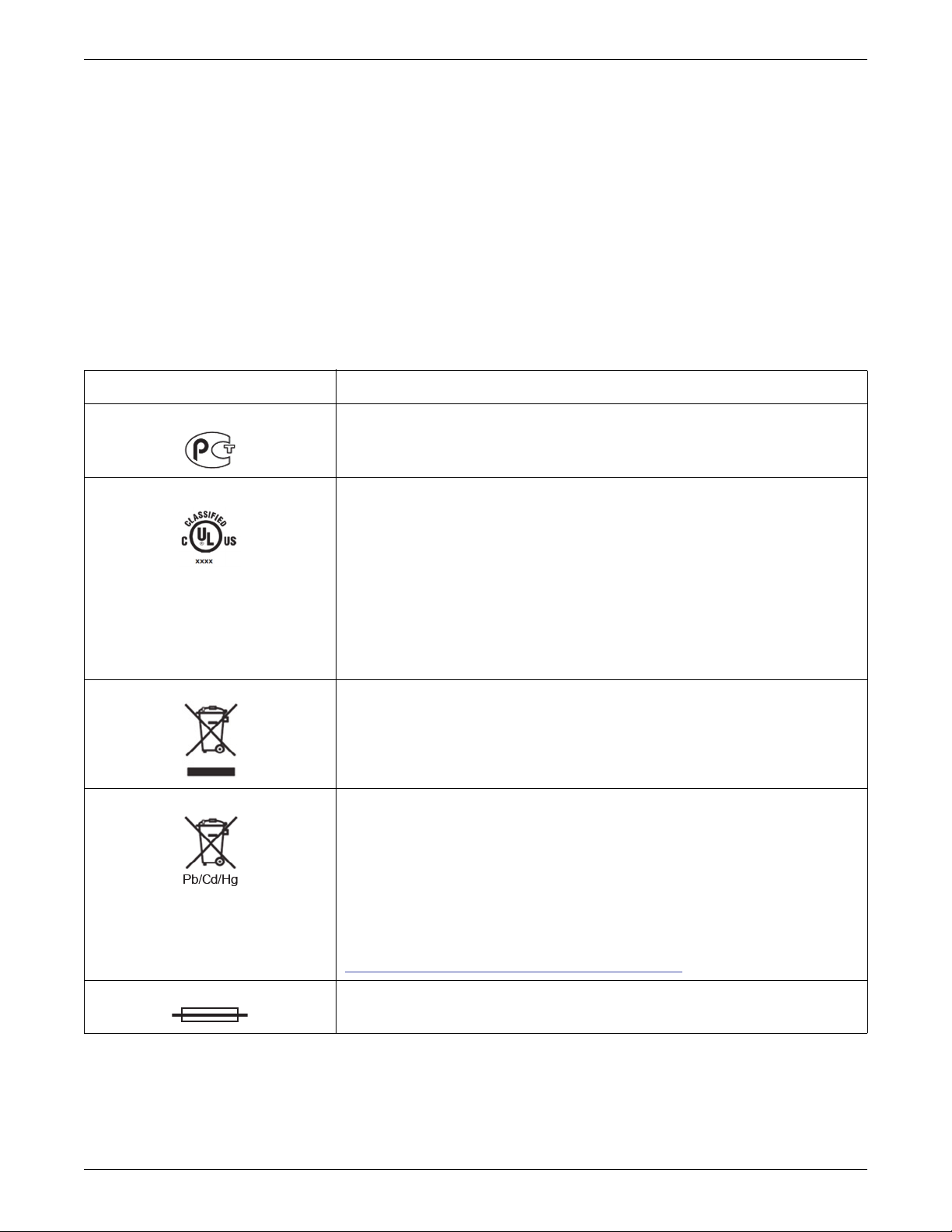
Introduction
Service
Refer equipment servicing to GE Healthcare authorized service personnel only. Any unauthorized
attempt to repair equipment under warranty voids that warranty.
Any unauthorized attempt to install third-party software on a system under warranty, voids that
warranty.
It is the user’s responsibility to report the need for service to GE Healthcare or to one of their
authorized agents.
Equipment Symbols
Equipment Symbols Descriptions
PCT (GOST-R) Mark
Compliance with applicable requirements for Russia.
Underwriters Laboratories, Inc.
Non-US Systems:
Medical – general medical equipment as to electrical shock, fire and mechanical hazards only
in accordance with UL60601-1, CAN/CSA C22.2 No. 601.1, ANSI/AAMI ES60601-1 (2005,
3rd ed.), AND CAN/CSA-C22.2 No. 60601-1 (2008).
US-Only Systems:
Classified by Underwriters Laboratories Inc. with respect to electric shock, fire, mechanical
and other specified hazards, only in accordance with UL 2601-1, CAN/CSA C22.2 No. 601.1,
IEC 60601-1 and IEC 60601-1-1.
WEEE
Indicates that the waste of electrical and electronic equipment must not be disposed as
unsorted municipal waste and must be collected separately. Please contact an authorized
representative of the manufacturer for information concerning the decommissioning of your
equipment.
WEEE
The separate collection symbol is affixed to a battery, or its packaging, to advise you that the
battery must be recycled or disposed of in accordance with local or country laws. The letters
below the separate collection symbol indicate whether certain elements (Pb=Lead,
Cd=Cadmium, Hg=Mercury) are contained in the battery. To minimize potential effects on the
environment and human health, it is important that all devices with batteries are properly
recycled or disposed.
Information on the potential effects on the environment and human health of the substances
used in batteries is available at this url:
http://www.gehealthcare.com/euen/weee-recycling/index.html
Fuse
1-16 Mac-Lab/CardioLab/Centricity Cardiology INW Service Manual 2063076-010H EN
Page 31

Equipment Symbols Descriptions
Equipotential Ground Point
A nonessential electrical connection which may be used to connect the chassis to other
equipment to achieve the same potential.
Standby
Mains Power Switch
1 is on. 0 is off.
Insert SD
Indicates that the computer has an SD drive located near this symbol.
Introduction
Insert SD Here
Type CF Equipment that is Defibrillator Proof
Type CF Applied Part: Isolated (floating) applied part suitable for intentional external and
internal application to the patient excluding direct cardiac application. The “paddles” outside
the box indicate that the part is defibrillator proof.
(Medical Standard Definition:) F-Type applied part (floating/isolated) complying with the
specified requirements of IEC 60601-1/UL 2601-1/CSA 601.1 Medical Standards provide a
higher degree of protection against electric shock than that provided by Type B applied parts.
Type BF Equipment that is Defibrillator Proof
Type BF Applied Part that is defibrillator proof: Isolated (floating) applied part suitable for
intentional external and internal application to the patient excluding direct cardiac application.
“Paddles outside the box indicate the applied part is defibrillator proof.
(Medical Standard Definition:) F-Type applied part (floating/isolated) complying with the
specified requirements of IEC 60601-1/UL 2601-1/CSA 601.1 Medical Standards provide a
higher degree of protection against electric shock than that provided by Type B applied parts.
Atmospheric Pressure Limits
Temperature Limits
2063076-010H EN Mac-Lab/CardioLab/Centricity Cardiology INW Service Manual 1-17
Page 32

Introduction
Equipment Symbols Descriptions
Humidity Limits
IPX1
Protected against potentially harmful effects of vertically falling water drops.
Consult accompanying documents.
Caution
NOTE: Per IEC 60601-1 2nd ed, the description of this symbol is “Attention, consult
ACCOMPANYING DOCUMENTS”.
Mandatory Action: Follow Instructions For Use
Read and understand the operator's manual before using the device or product.
As a mandatory action sign, this symbol is identified by a blue background and white symbol.
WARNING
General warning sign.
This symbol is identified by a yellow background, black triangular band, and a black symbol.
Input Symbol
Identifies the device manufacturer and manufacturing date.
Identifies the product’s catalog, or orderable part number.
Identifies the unit’s serial number.
Battery
1-18 Mac-Lab/CardioLab/Centricity Cardiology INW Service Manual 2063076-010H EN
Page 33

Equipment Symbols Descriptions
Communication
ePort Connection
Power
Network Connection/Interface
Introduction
Serial Connection/Interface
USB Connection Interface
WARNING: SHOCK HAZARD
Remove power cord from the mains source by grasping the plug. Do not pull on the cable.
This may cause cable damage, which could result in loss of protective earthing or exposure to
mains voltage.
Zero All
2063076-010H EN Mac-Lab/CardioLab/Centricity Cardiology INW Service Manual 1-19
Page 34

Introduction
1-20 Mac-Lab/CardioLab/Centricity Cardiology INW Service Manual 2063076-010H EN
Page 35

Chapter 2
Equipment Overview
2063076-010H EN Mac-Lab/CardioLab/Centricity Cardiology INW Service Manual 2-1
Page 36

Equipment Overview
Serial Number Identification
Every Mac-Lab/SpecialsLab system has a unique serial number for identification. The serial
number appears on the product labels which are located (while facing the product):
Acquisition Computer — on the right side
Review Workstation — on the top
Centricity Cardiology INW Server — on the front
Integrated Electronics Box (IEB) — on the back
PDM — on the bottom
PDM Base Station — on the back
TRAM-RAC — on the right side
TRAM — on the back
CardioLab II Plus Amplifier — on the back
CO
Module — on the right side
2
2
1
GE MEDICAL SYSTEMS INFORMATION TECHNOLOGIES, INC., 8200 WEST TOWER AVE., MILWAUKEE, WISCONSIN USA
Identification Tag
Item Name Description
1 Manufacture Date Date of manufacture in YYYY-MM format.
2 Part Number of Product GE Healthcare part number for product.
3 Product Code Description Identifier for type of product.
4 Serial Number and
Barcode
5 Manufacturer Information Name and address of device manufacturer.
Unique serial number for identification.
Encoded as a barcode below the displayed number.
3
4
5
2-2 Mac-Lab/CardioLab/Centricity Cardiology INW Service Manual 2063076-010H EN
Page 37

Typical Acquisition System Configuration
IEB
Amplifier
CIM
Bed
RF
Generator
Catheter
Personality
Module
Mouse
Printer
Speakers
Stimulator
Real-Time
Monitor
Review
Monitor
Remote
Real-Time
Monitor
3" Ceiling Conduit
3" Floor Conduit
3" Floor Conduit
Remote
Review
Monitor
Image
Monitor
INW
Server
CVIS
Server
Network
Switch
To Hospital Network
Keyboard
Workstation
Dashed lines indicate CardioLab/ComboLab only
Procedure Room
Control Room
IT Control Room
Monitor
Boom
CPU
UPS
Vivid
Trackball
CARTO
Vivid
INW Backup Device
PDM
BASE
STATION
This system may consist of either Mac-Lab (hemodynamic), CardioLab (electrophysiologic) or
ComboLab (both systems).
NOTE: This document illustrates the HP z600 computer cabling connections only. Refer to
version 6.8.1 service manuals for HP xw8400 computer cabling connections.
The system may be standalone or connected to a network. Network installations include a
Centricity Cardiology INW server. In this manual, INW refers to Centricity Cardiology INW. It may
be connected to an optional CVIS server.
The system may also include a CardioLab II Plus Amplifier, also referred to as CLab II Plus.
The following block diagram shows a typical setup.
Equipment Overview
2063076-010H EN Mac-Lab/CardioLab/Centricity Cardiology INW Service Manual 2-3
Page 38

Equipment Overview
Control Room Components
Acquisition Computer: The Acquisition Computer provides the ability to record the patient's
real time waveform data. It uses Windows and has the following drives:
DVD-Drive: used for installation and service of the computer.
SD Drive: used to store backup copies of patient procedure data.
External Blu-ray drive (optional): used to copy procedure data from DVD-RAM media to
SD media.
Monitors: Two monitors are standard to display Real-Time and Review windows. An optional
third monitor displays images acquired from the X-ray and ultrasound system.
Integrated Electronics Box (IEB): The IEB provides isolated power to system components
and distributes video and communication signals to the control and procedure rooms.
Uninterrupted Power Supply (UPS): The UPS provides emergency power to the acquisition
computer in the event of a power outage. It will sustain power to the computer for a minimum
of 20 seconds. It does not power the monitors during an outage.
NOTE: The UPS is external to the IEB and provides uninterrupted power to the HP computer.
The monitors and other peripherals will not remain on if power is lost.
Analog Output Box (optional): Distributes the ECG or Intracardiac signals from the Amplifier
to other equipment.
Printer: Used to print snapshots, images and reports during or after a procedure.
Barcode scanner (optional): Used to scan in supplies and medication used in a procedure.
CARTO Mapping System (optional) - CardioLab or ComboLab systems only: Provides
3D electroanatomical cardiac maps to the CardioLab.
Cardiac Stimulator (optional) - CardioLab or ComboLab systems only: Provides direct
cardiac stimulation to assist the physician during a CardioLab case.
Vivid System Remote Trackball (optional): Provides the ability to control the GE Vivid
Ultrasound System from the control room.
Desk (optional): Provides a workspace for control room components.
2-4 Mac-Lab/CardioLab/Centricity Cardiology INW Service Manual 2063076-010H EN
Page 39

Procedure Room Components
Monitors: One remote monitor is standard and is software switchable between Real-Time and
Review windows. A second monitor is optional.
Remote Speakers: Provide output for ECG QRS tone and optional audible indicators in the
procedure room.
TRAMNet or PDM: The TRAMNet or PDM acquires invasive pressure and ECG signal data
for Mac-Lab systems. It also acquires patient vital data such as respiration rate, noninvasive
blood pressure, SpO
TRAMNet consists of a Remote Acquisition Case (RAC 4A) and a Transport Remote
Acquisition Module (TRAM). The PDM is powered by the PDM Base Station unit.
CardioLab II Plus Amplifier - CardioLab or ComboLab systems only: The Amplifier
gathers intracardiac and surface ECG data for both the CardioLab and ComboLab systems.
Catheter Input Modules - CardioLab or ComboLab systems only: Used for connecting
intracardiac catheters to the CardioLab II Plus Amplifier.
RF Filter Box - CardioLab or ComboLab systems only: Filters RF noise from intracardiac
signals acquired by an ablation device.
CO
Module (optional): The CO2 module plugs into the RAC 4A and displays the patient's
2
respiration data on the Mac-Lab System.
Remote Operators Terminal (RMOT) (optional): The RMOT consists of two monitors, a
keyboard and a mouse remotely connected to the Acquisition system to provide remote
control of the Acquisition computer in the procedure room.
Large Display Monitor (LDM) (optional): The LDM is a large widescreen flat-panel LCD
monitor used for simultaneous display of several image sources, including the Acquisition
system.
Analog Output Box (optional): Distributes heart rate and blood pressure signals from the
TRAMNet and Amplifier to other equipment.
CARTO System (Patient Interface Unit) (optional) - CardioLab or ComboLab systems
only: The CARTO PIU gathers data for the CARTO system.
Ablation Device (optional) - CardioLab or ComboLab systems only: An RF ablation
device that burns heart tissue or cryogenic device that freezes the tissue controlled by the
physician or technician.
Force Sense Device (optional): A device which measures the amount of pressure between
the tip of an ablation catheter and the tissue with which it is in contact.
Vivid System (optional): A digital imaging GE Ultrasound system.
Nurse’s Review Workstation (optional): The Nurse’s Workstation is a system used in the
procedure room during a study. Provides the operator with the ability to participate in an active
study and perform actions such as document administered medications and supplies
consumed.
and temperature for both Mac-Lab and CardioLab systems. The
2
Equipment Overview
2063076-010H EN Mac-Lab/CardioLab/Centricity Cardiology INW Service Manual 2-5
Page 40

Equipment Overview
IT Control Room Components
Network Switch: Provides connection between network components and segments.
Centricity Cardiology INW Server: Provides the ability to review patient data during and after
data acquisition and allows for a centralized point of data access.
Monitor (temporary): Displays screens during server installation only. Removed after
server installation is complete.
Keyboard (temporary): Provides an input for commands and text entries during server
installation only. Removed after server installation is complete.
CVIS Server: Provides a central location to manage data regarding staff, supplies, inventory,
patient scheduling, patient information and statistical reports.
Monitor (temporary): Displays screens during server installation only. Removed after
server installation is complete.
Keyboard (temporary): Provides an input for commands and text entries during server
installation only. Removed after server installation is complete.
Network Connections
CVIS Server
Hospital
Enterprise
OR
Mac-Lab CardioLab
INW Backup Device
INW Server
Review
Workstation
2-6 Mac-Lab/CardioLab/Centricity Cardiology INW Service Manual 2063076-010H EN
Page 41

Review Workstations
Mac-Lab/CardioLab software can run on hardware provided by GE (Review Workstation) or on
hardware provided by the hospital (Software Only Review Workstation).
Nurse's Workstation Components
The Nurse's Workstation is a system used in the procedure room during a study.
GE Client Workstation: Provides the operator with the ability to participate in an active study
and perform actions such as document administered medications and supplies consumed.
Isolation Transformer: Provides isolated power for components.
Monitor: Used to display the Review window. One monitor is standard.
Barcode Scanner (optional): Used to scan in supplies and medications used in a procedure.
Remote Review Workstation Components
The Remote Review Workstation is a system installed in the physician’s office or an area outside
the laboratory.
Equipment Overview
GE Client Workstation: Used to review previously acquired procedure data and generate
reports.
Isolation Transformer: Provides isolated power for components.
Monitor: Used to display the Review window. One monitor is standard.
Printer (optional): Used to print snapshots, images and reports after a procedure.
Pre/Post Review Workstation Components
The Pre/Post Review Workstation is a Review Workstation typically located in a Holding Area for
the entry of basic patient demographics, clinical data and patient events prior to, or after, the
patient's entry into the Laboratory.
GE Client Workstation: Used before and after the procedure to record patient information.
DASH/Solar Monitor: Connected to the Pre/Post Workstation to acquire patient vitals during
pre or post procedure monitoring.
Monitor: Used to display the Review window. One monitor is standard.
Isolation Transformer: Provides isolated power for the Pre/Post Workstation.
Mobile Workstand (optional): Provides portable support for Pre/Post Workstation
components.
Barcode Scanner (optional): Used to scan in supplies and medications used in a procedure.
2063076-010H EN Mac-Lab/CardioLab/Centricity Cardiology INW Service Manual 2-7
Page 42

Equipment Overview
Supported Peripheral Devices
The following peripheral devices are support for use on Mac-Lab/CardioLab/Centricity Cardiology
INW system:
DASH: 3000/4000/5000
Solar: 8000i and 8000M connected with a TRAM or PDM
Vivid: i/q
FFR (Mac-Lab only): Radi PressureWire Aeris and Volcano SmartMap Pressure Instrument
Ablation (CardioLab only):
Atakr II (Model: 4803) RF (Radio frequency) ablation device
EPT-1000 (Model: 800T) RF ablation device
Stockert RF ablation device
IBI 1500T (Software version: v1.25) RF ablation device
HAT 300S RF ablation device
CryoCath (Model: Gen3) cryo-ablation device
JLLCABL-IT RF ablation device
Maestro 3000
Force device availability varies by region, please see your sales representative.
Cardiac Stimulator (CardioLab only): MicroPace EPS 320, Bloom Stimulator
Mapping System (CardioLab only): CARTO XP v10 or CARTO 3
X-ray systems: refer to the product's DICOM conformance statement on the following GE
Healthcare website:
http://www.gehealthcare.com/usen/interoperability/dicom/products/cvinfosys_dicom.html
2-8 Mac-Lab/CardioLab/Centricity Cardiology INW Service Manual 2063076-010H EN
Page 43

System Hardware
WARNING: SHOCK HAZARD
To reduce the risk of shock and equipment damage, use safe working practices
when servicing electrical equipment.
Acquisition System Components
HP Computer
The HP computer used for Acquisition systems has the following components:
Primary Hard Drive with two partitions
C: Application partition
D: Data partition
Equipment Overview
SD drive with front access (Drive E:)
Used on all new HP z600 and older z600s with upgrade
NOTE: The drive used to store backups of application studies is determined by the file paths set
under System Settings in the main application menu.
DVD-RAM drive (Drive F:)
Used on HP z600 with upgrade
NOTE: The drive used to store backups of application studies is determined by the file paths set
under System Settings in the main application menu.
DVD drive (Drive F:)
Used on new HP z600 and some z600s with upgrade
SD drive with internal access (Drive G:)
Used on HP z600 with upgrade
Used on new HP z600
NOTE: The drive used for GE Service to store upgrade/migration data as well as backed up
system settings.
2063076-010H EN Mac-Lab/CardioLab/Centricity Cardiology INW Service Manual 2-9
Page 44

Equipment Overview
Four standard expansion cards (plus optional cards)
HP z600: Matrox M9140 video board provides video out for the Real-Time (Video 1),
Review (Video 2) and optional (Video 3) monitors.
TRAMNet to Ethernet Adapter board for communication with the TRAM in the RAC 4A.
PCI Communication board provides Amplifier Communication, Analog and Digital I/O and
Switched video (the video out from the IEB).
Dual NIC Adapter board provides Network connection.
Optional on HP z600: Matrox Solios x4 PCIe (eCL) board used to capture images from
Vivid system for CardioICE support.
Optional on older HP z600 with upgrade: Matrox Odyssey eA board used to capture
images from an X-Ray or other imaging system.
Optional on new HP z600: Matrox Odyssey Helios board used to capture images from an
X-Ray or other imaging system.
2-10 Mac-Lab/CardioLab/Centricity Cardiology INW Service Manual 2063076-010H EN
Page 45

External Components and Connections for the HP z600
2
3
4
5
7
6
1
Equipment Overview
Label Part Number Description
1 2028599-002 DVD-RAM Drive (used on some HP z600 with upgrade)
2054838-001 DVD Drive (used on new HP z600 and some HP z600 with upgrade
2057730-001 ADA Drive (used on HP z600 with upgrade)
2 2050067-001 SD Drive
3 N/A Power Switch
4 N/A LEDs, USB, Firewire and Audio connections
5 N/A Backplane I/O panel
6 N/A Board Slots
7 N/A AC Power
Not Shown 2026539-001 HP USB 2-Button Optical Mouse with Wheel
Not Shown Various Keyboard (dependent on language)
only)
2063076-010H EN Mac-Lab/CardioLab/Centricity Cardiology INW Service Manual 2-11
Page 46

Equipment Overview
12 3
1
2
DVD-RAM Drive
The DVD-RAM drive (used with older HP z600 with upgrade) can also read/write to CDs. The
recommended disks have a capacity of approximately 4.7 GB per side.
NOTE: The drive used to store backups of application studies is determined by the file paths set
under System Settings in the main application menu.
Item Description
1 DVD-RAM Drive Jumpers
2 IDE Connector
3 Power Connector
SATA-to-IDE Converter - HP z600 Only
The DVD-RAM drive is connected using a SATA-to-IDE converter.
Item Description
1 SATA Connection
2 4-pin Connection
Not Shown IDE Connection (on back of device)
2-12 Mac-Lab/CardioLab/Centricity Cardiology INW Service Manual 2063076-010H EN
Page 47

DVD Drive – New HP z600 Only
The DVD drive (used on new HP z600) requires no jumper settings prior to installation.
ADA Drive
The ADA drive (used with some older HP z600 with upgrade) can also read/write to CDs. The
recommended disks (DVD-RAM) have a capacity of approximately 4.7 GB per side. The same
media used in the DVD-RAM drive can be used in the ADA drive.
NOTE: The drive used to store backups of application studies is determined by the file paths set
under System Settings in the main application menu.
SD Drive
The SD drive (used on all HP z600 and older HP xw8400 with upgrade) requires no jumper
settings prior to installation. The SD drive contains two SD card slots: one external access slot
(front of computer) for facility personnel use and one internal access slot for use by GE service
personnel.
NOTE: The drive used to store backups of application studies is determined by the file paths set
under System Settings in the main application menu.
Equipment Overview
External Blu-ray Drive – Optional
The external Blu-ray drive (optional) is used to copy procedure data from DVD-RAM media to SD
media.
NOTE: The drive is determined by the file paths set under System Settings in the main
application menu.
2063076-010H EN Mac-Lab/CardioLab/Centricity Cardiology INW Service Manual 2-13
Page 48

Equipment Overview
HP z600 Installed Boards
HP z600 Dual NIC Adapter Board
1
2
3
4
5
6
Part Number: 2047766-001
Subcomponents of Dual NIC bracket:
Dual NIC Assembly Part Number: 2057429-001
Serial Connector Part Number: 2036936-017 (RoHS) 2057430-001 (non-RoHS)
Location: Slot 1
Function: Network connection card, ablation connection card.
I/O: Two network connection jacks, one serial port (for connection to ablation devices)
Uses internal serial connection from motherboard:
2-14 Mac-Lab/CardioLab/Centricity Cardiology INW Service Manual 2063076-010H EN
Page 49

Equipment Overview
1
2
3
4
5
6
Matrox M9140 Quad Video Board
Part Number: 2049434-001
Location: Slot 2
Function: Video out for Monitor 1, Monitor 2 and Monitor 3 (optional)
I/O: One proprietary connector. Provides four DVI/VGA output ports through a custom
connector.
2063076-010H EN Mac-Lab/CardioLab/Centricity Cardiology INW Service Manual 2-15
Page 50

Equipment Overview
1
2
3
4
5
6
1
2
3
4
5
6
HP z600 Matrox Helios Video Board (Optional)
Part Number: 2052113-001
Location: Slot 3
Function: Image capture for X-Ray or other imaging systems. Used on CardioICE and
I/O: Two DVI connectors
CardioImage Acquisition systems only.
HP z600 Matrox Odyssey eA Video Board (Optional)
Part Number: 2049435-001
Location: Slot 3 (existing Z600 computers)
Function: Image capture for X-Ray or other imaging systems. Used on CardioICE and
CardioImage Acquisition systems only.
I/O: Two DVI connectors
2-16 Mac-Lab/CardioLab/Centricity Cardiology INW Service Manual 2063076-010H EN
Page 51

Matrox Solios Video Board (Optional)
1
2
3
4
5
6
1
2
3
4
5
6
Part Number: 2031725-001
Location: Slot 4
Function: Video in from Vivid. Used on CardioICE Acquisition systems only.
I/O: Two DVI Connectors (only one is used)
Equipment Overview
HP z600 TRAMNet to Ethernet Adapter Board
Part Number: 2009937-004 (RoHS) or 2009937-003 (non-RoHS)
Location: Slot 5
Function: Provides communication with the TRAM in the RAC 4A and converts signals from
the TRAM to the ethernet.
I/O: Network Interface Port and 9-Pin D connector
2063076-010H EN Mac-Lab/CardioLab/Centricity Cardiology INW Service Manual 2-17
Page 52

Equipment Overview
1
2
3
4
5
6
HP z600 PCI Communication Board
Part Number: 2014935-003 (RoHS) or 2014935-002 (non-RoHS)
Location: Slot 6
Functions:
I/O: D-Connector to IEB, Fiber Optic Jacks to the Amplifier
Communicates with the CLab II Plus Amplifier via the fiber optic connectors
Analog and Digital communication with the IEB via the D-Connector
Provides the video switching signal for the Switched Video output on the IEB via the D-
Connector
2-18 Mac-Lab/CardioLab/Centricity Cardiology INW Service Manual 2063076-010H EN
Page 53

Integrated Electronics Box (IEB)
The IEB provides power to local system components and signal pass through video and
communications. Three versions of the IEB are available to handle different line voltages: 100, 120
and 240 VAC.
The IEB consists of the following components:
Video Multiplexer (VID MUX) board to distribute video signals from the video cards in the
Acquisition system to the monitors.
DB Connect board to provide signal pass through for other system components.
Isolation transformer:
Conforms to IEC 60601-1
2.0 kVA medical grade high-isolation transformation
Provides either 120 VAC (for 100 and 120 VAC systems) or 240 VAC. The primary and
secondary windings are wired in parallel for 120 VAC and in series for 240 VAC.
CAUTION: CONNECTIONS
Equipment Overview
If the transformer must be disconnected for any reason, ensure the
connections are correct.
UPS (either 100, 120, or 240 VAC) and Power Distribution panel provide conditioned power to
local system components.
NOTE: The UPS is external to the IEB and provides uninterrupted power to the Acquisition
system. The monitors and other peripherials will not remain on if power is lost.
Depending on which IEB is installed, a modem and modem power supply for dial-up
communication may be present. The power supply accepts any line voltage and converts
it into 9 VDC.
2063076-010H EN Mac-Lab/CardioLab/Centricity Cardiology INW Service Manual 2-19
Page 54

Equipment Overview
External Components and Connections
Item Part Number
1 2003681-004 2003681-003 VID MUX Board
2 2003680-002 2003680-001 DB Connect Board
3 N/A N/A Power Connections. The bottom right connector is for the
4 N/A N/A Thermal Overcurrent Circuit Breaker. This breaker protects all
5 N/A N/A Main Power Switch. This switch controls power to all internal
Non-RoHS Part
Number
Acquisition system and the four vertical connectors on the right and
left are for peripheral equipment.
internal components and external devices connected to the IEB.
components and external devices except the Acquisition system.
Description
Both the Main Power switch on the front of the IEB and the Thermal Overload circuit breaker on
the back must be on for the system to power up.
2-20 Mac-Lab/CardioLab/Centricity Cardiology INW Service Manual 2063076-010H EN
Page 55

Video Multiplexer (VID/MUX) Board
Equipment Overview
Item Description
1 Switched video out (Video 1 or 2). This is used when the facility has only one remote monitor. To switch
monitors:
Mac-Lab: Go to the main menu and select Windows > Physician Video.
CardioLab: Use the dropdown box just under the main menu.
2 Video 1 (Real-Time) out to local monitor (bottom) and remote monitor (top)
3 Video 2 (Review) out to local monitor (bottom) and remote monitor (top)
4 Video 3 (CardioImage) out to local monitor (bottom) and remote monitor (top)
5 (L to R) Video 1, Video 2, Video 3 in from Acquisition system Matrox Quad Video board for Vid 1, Vid 2 and
Vid 3
The VID MUX board amplifies (±5V 1.25A) from the internal IEB DC power supply (refer to Internal
Components and Connections on page 2-24) and distributes the video signals from the HP
Computer (refer to HP z600 Video Connections on page 2-54).
2063076-010H EN Mac-Lab/CardioLab/Centricity Cardiology INW Service Manual 2-21
Page 56

Equipment Overview
DB Connect Board
WARNING: SHOCK HAZARD
Do not connect analog input or analog output cables to patient-isolated
equipment interfaces. This could compromise patient safety.
Item Description
1 Analog I/O Communication: Connects to the Acquisition system PCI Communication board.
2 Analog In: From another system (for example, Fluoro and so on)
3 Connection to the Analog Output Box
4 Analog Out (for example, Stimulator, Vivid and so on).
5 I/O TRAM (includes 16.5 VDC power)
6 Output to Acquisition system TRAMNet to Ethernet to Adapter board
Refer to the following cabling diagrams:
Communications Connections on page 2-55
TRAM/Amplifier Connections on page 2-56
2-22 Mac-Lab/CardioLab/Centricity Cardiology INW Service Manual 2063076-010H EN
Page 57

Power Connections
Item Description
1 and 5 AC out to local equipment (6A at 120 VAC
2 Thermal Overcurrent circuit breaker. Protects all internal components and external devices connected to
the IEB.
3 AC main power in (15A at 120 VAC
4 AC power out to UPS (2A at 120 VAC
max
; 7A at 240 VAC
max
; 1A at 240 VAC
max
; 3A at 240 VAC
)
max
max
Equipment Overview
)
max
).
Refer to the cabling diagram, Power Connections on page 2-53.
2063076-010H EN Mac-Lab/CardioLab/Centricity Cardiology INW Service Manual 2-23
Page 58

Equipment Overview
Internal Components and Connections
Item Part Number
1 2003681-004
2003680-002
2 2013535-001 Power Supply: Provides + 5 VDC 1.25A for the VID/MUX board and
Non-RoHS Part
Number
2003681-003
2003680-001
VID/MUX Board Assembly
DB Connect (I/O) Board Assembly
+16.5 VDC for the RAC-4A.
Description
2-24 Mac-Lab/CardioLab/Centricity Cardiology INW Service Manual 2063076-010H EN
Page 59

Uninterruptible Power Supply (UPS)
The UPS is designed to maintain power to the Acquisition system during a power outage for up to
20 seconds.
NOTE: The UPS is external to the IEB and provides uninterrupted power to the Acquisition
system. The monitors and other peripherials will not remain on if power is lost.
Equipment Overview
Part Number
2034077-002 2034077-001 UPS Powercom, 120V, 50/60 Hz, 1500 VA, BNT
2034078-002 2034078-001 UPS Powercom, 230V, 50/60 Hz, 1500 VA, BNT
2034079-002 2034079-001 UPS Powercom, 100V, 50/60 Hz, 1500 VA, BNT
2063076-010H EN Mac-Lab/CardioLab/Centricity Cardiology INW Service Manual 2-25
Non-RoHS Part
Number
Description
Page 60

Equipment Overview
Review Workstation
There are several configuration options for use of the Review Workstations in a networked system
environment.
Nursing Workstation: A system used in the procedure room during a study.
Remote Review Workstation: A system installed in the physician’s office or an area outside
the laboratory.
Pre/Post Procedure Workstation: Typically located in a Holding Area for the entry of basic
patient demographics, clinical data and patient events prior to, or after, the patient's entry into
the Laboratory.
NOTE: Automatic vitals logging is also available with the optional DASH and Solar monitor
interface.
NOTE: When used in a patient care area, the hardware must meet IEC60601-1. This can be
achieved through the use of a medical grade computer, separate isolation transformer or
other means as determined by appropriate hospital personal.
The Review Workstation has the following components:
Primary Hard Drive with two partitions:
C: Application partition
D: Data partition
DVD drive (E:)
NOTE: On the Review Workstation, this drive is used to service the system.
Secondary Hard Drive (G:)
2-26 Mac-Lab/CardioLab/Centricity Cardiology INW Service Manual 2063076-010H EN
Page 61

External Components and Connections for the Review Workstation
Equipment Overview
1
4
5
6
2
7
8
9
3
Item Part Number Description
1 N/A Power and Reset Switches
2 N/A DVD Drive
3 N/A USB and Audio Connections (behind covers)
4 N/A AC Power
5 Various Keyboard (dependent on language)
6 N/A Com Port for DASH/Solar Connection
7 N/A Video Input
8 N/A USB 2-Button Optical Mouse with Wheel
9 N/A RJ-45 Port to Network
2063076-010H EN Mac-Lab/CardioLab/Centricity Cardiology INW Service Manual 2-27
Page 62

Equipment Overview
4
1
5
6
23
2
Mobile Workstand
Refer to the instructions included with the mobile workstand for details on how to place the GE
hardware on an assembled GE mobile workstand (PN 2008203-001).
Item Part Number Description
1 N/A DASH Monitor
2 N/A Mouse or Barcode Scanner Location
3 N/A Keyboard Location
4 2063576-001
2053147-001
5 2004195-001 Isolation Transformer
6 2079070-002 LCD Monitor
2048962-001
Review Workstation Computer
2-28 Mac-Lab/CardioLab/Centricity Cardiology INW Service Manual 2063076-010H EN
Page 63

Monitors
Equipment Overview
The standard Acquisition system comes with two monitors and may have a third optional monitor.
The monitors include:
A Real-Time monitor to display active patient information. It is usually located on the left.
A Review monitor to display saved patient study information.
An optional Image monitor (used with the CardioImage option) displays live or frozen video
images.
A single remote monitor is standard and receives input from the switched video out (Video 1 or 2)
jack on the IEB (see External Components and Connections on page 2-20).
To switch video for the Mac-Lab go to the main menu and select Windows > Physician
Video.
To switch video for the CardioLab use the drop-down box just under the main menu.
2063076-010H EN Mac-Lab/CardioLab/Centricity Cardiology INW Service Manual 2-29
Page 64

Equipment Overview
Patient Data Module (PDM)
PDM acts as an amplifier for the Mac-Lab system and is responsible for patient data acquisition. It
is connected to the PDM Base Station unit which powers the PDM and is placed in the procedure
room near the patient table. The PDM rests in a dock that can be mounted to a bed rail, a pole, or
a stand which also holds the PDM Base Station.
PDM has the following patient data input features:
Electrocardiogram (ECG): Green connector (5 or 10 leads)
Thermal Dilution Cardiac Output (TDCO) or Temperature: Brown connector
Invasive Blood Pressure (IBP): Red connectors
Pulse Oximetry (SpO
Non-Invasive Blood Pressure (NIBP): Black Connector
Analog Out and Defib/Sync: White connector
PDM does not support CO
): Blue Connector
2
data acquisition.
2
The PDM can monitor up to four invasive blood pressures when two Y-adapter cables are used.
Plugging one Y-adapter cable into the P1/P3 connector on the PDM allows two separate invasive
blood pressures to be monitored from that connector, for a total of three pressures. Plugging a
second Y-adapter cable into the P2/P4 connector on the PDM allows two separate invasive blood
pressures to be monitored from that connector, for a total of four pressures.
NOTE: The labeling on the Y-adaptor cable (IP1 and IP2) corresponds to the first and second
pressures listed below the connector on the PDM. For example, if a Y-adaptor cable is
plugged into the P1/P3 connector on the PDM, the IP1 represents P1 and the IP2
represents P3.
NOTE: The PDM waveform defibrillation recovery time is ten seconds.
Refer to Appendix E for information about the PDM battery and for a list of accessories approved
for use with the PDM. Refer to the documentation included with the PDM module for additional
information. Revisions up to 2.1 are supported.
Ensure that the cables are compatible with the PDM, including that the SpO
SpO
sensor type.
2
2-30 Mac-Lab/CardioLab/Centricity Cardiology INW Service Manual 2063076-010H EN
cable matches the
2
Page 65

WARNING: SHOCK HAZARD
Defibrillator protection is only guaranteed when approved accessories are
used. Do not use unspecified accessories.
Analog Out and Defib/Sync
The white connector on the PDM may be used to provide Analog Output or Defib/Sync signals to
external devices.
Analog Out: This supplies either an ECG or an invasive pressure signal to another device.
Refer to Analog Output Box on page 2-46 for details.
Defib/Sync: This provides the ECG synchronization signal for an external defibrillator,
intraaortic balloon pump or ventilator. The sync signal is generated using the currently
selected ECG analog output lead. Use the Defib/Sync Interface cable (PN 2017842-001) to
access this output.
An optional splitter (PN 2024565-002 (RoHS) or 2024565-001 (non-RoHS) may be used to
provide both Analog Out and Defib/Sync signals simultaneously.
Equipment Overview
2063076-010H EN Mac-Lab/CardioLab/Centricity Cardiology INW Service Manual 2-31
Page 66

Equipment Overview
12 3
PDM Base Station
The PDM Base Station powers the PDM and routes Ethernet signals between the Acquisition
system and the PDM. The PDM and Base Station are located in the procedure room near the
procedure table.
A green power light indicates the Base Station is attached to AC power and is turned on.
Item Description
1 To Acquisition System Workstation
2To PDM
3 AC power 100-240VAC 50/60Hz
2-32 Mac-Lab/CardioLab/Centricity Cardiology INW Service Manual 2063076-010H EN
Page 67

PDM and Base Station Mounting Options
The PDM Base Station can be mounted to a stand where the PDM is also docked.
NOTE: The green light on the front of the PDM Base Station is quite bright. It is suggested that
the PDM Base Station is installed facing away from the physician, toward the foot or the
far side of the bed.
Equipment Overview
The PDM Base Station may also rest with its feet on the floor, connected to the PDM by a longer
cable. In this setup, the PDM dock is attached to the pole/rail clamp, which clamps onto a bed rail
or pole. The pole/rail clamp is attached and detached by adjusting the clamp knob. Ensure the
knob is fully tightened when clamping to bed rails and poles.
2063076-010H EN Mac-Lab/CardioLab/Centricity Cardiology INW Service Manual 2-33
Page 68

Equipment Overview
WARNING: TRIPPING HAZARD
Keep cables away from accessible walkways. Failure to do so may present a
tripping hazard and could result in cable damage.
WARNING: FALLING EQUIPMENT
Do not place the PDM more than 147 cm (58 in) from the floor when mounting
on an IV pole with a base less than 58 cm (23 in) in diameter. This may cause
the IV pole to tip over.
WARNING: SHOCK HAZARD
To reduce the risk of ingress of water into the equipment, do not mount the
PDM in a vertical position with the patient cables facing up or down.
2-34 Mac-Lab/CardioLab/Centricity Cardiology INW Service Manual 2063076-010H EN
Page 69

TRAMNet
Equipment Overview
Item Description
1 TRAM Module
2 To Analog Out Box
3 To IEB TRAM Connector
The TRAMNet consists of a Remote Acquisition Case (RAC-4A) and one TRAM module. The
TRAMNet is located in the procedure room near the procedure table.
The TRAM module receives patient inputs and then transmits signal data to the IEB and other
equipment through the Analog Output Box (refer to the cabling diagrams in TRAM/Amplifier
Connections on page 2-56).
TRAM Module Inputs:
Electrocardiogram (ECG) - green connector (5 or 10 leads)
Thermal Dilution Cardiac Output (TDCO) - brown connector
Invasive Blood Pressure (IBP) - 3 red connectors
Non-Invasive Blood Pressure (NIBP) - black connector
Pulse Oximetry (SpO
) - blue connector
2
2063076-010H EN Mac-Lab/CardioLab/Centricity Cardiology INW Service Manual 2-35
Page 70

Equipment Overview
Outputs: Analog output connector.
The following TRAM modules are supported:
250SL
400 SL, 450SL, 451, 451M, 451N, 451N5
650SL
The following software versions are supported:
7A, 7B, 7C, 7D, 7E, 7F, 7H
8A, 8B, 8C, 8D
9A, 9B
10A, 10B
11A, 11B, 11 C
Refer to the documentation included with the TRAM module for additional information on
equipment and compatible accessories.
RAC 4A
The RAC 4A is the housing device for the TRAM and is mounted in the procedure room near the
procedure table. The RAC 4A can be placed on the floor or mounted to the table vertically or
horizontally and should be protected from fluids.
Refer to the documentation included with the TRAM module for additional information on
equipment and compatible accessories.
WARNING: SHOCK HAZARD
Use caution when cleaning the environment near equipment. Fluid ingress may
damage devices or compromise electrical safety.
CardioLab II Plus Amplifier
The CardioLab II Plus Amplifier is designed to amplify various types of cardiac signals that are
acquired from a patient and transmit them back to the CardioLab system. These signals include 12
Lead ECG, intracardiac and pressure signals.
2-36 Mac-Lab/CardioLab/Centricity Cardiology INW Service Manual 2063076-010H EN
Page 71

Equipment Overview
2063076-010H EN Mac-Lab/CardioLab/Centricity Cardiology INW Service Manual 2-37
Page 72

Equipment Overview
Front View
Front View 64/32 Channels - CardioLab II Plus Amplifier
Item Description
1 Catheter Inputs: Up to three catheter inputs will each accept a 32 pole catheter input module. Use the
CardioLab II Plus Catheter Input Modules (part number 301-00202-08) with the CardioLab II Plus Amplifier.
2 Power Indicators: The power indicator is on as long as the CardioLab II Plus Amplifier is turned on.
3 Communication Indicators: Three communication indicators show the status of the communication
between the acquisition computer and the CardioLab II Plus Amplifier.
When the XMT indicator is on, the CardioLab II Plus Amplifier is transmitting data to the acquisition
computer. The XMT indicator should remain on as long as the power indicator is on.
When the RCV CMD indicator is on, the CardioLab II Plus Amplifier is receiving data from the acquisition
computer. The RCV CMD indicator will turn on as long as an instruction is being received by the
amplifier.
When the RCV ERR indictor is on, the CardioLab II Plus Amplifier may not be receiving data from the
acquisition computer in a valid format or there may be a problem with the fiber optic cable.
4 Auxiliary Inputs: The auxiliary input will accept the Auxiliary Input Cable (part number 301-00205-08).
5 Stimulator Input: The stimulator input will accept a stimulator input cable. Use the 3 ft, 15 ft or 30 ft
Touchproof Stimulator Cables (part numbers, 301-00204-03, 301-00204-15, 301-00204-30, respectively)
with the CardioLab II Plus Amplifier.
6 ECG Inputs: The ECG input connector will accept a 10 lead ECG input cable.
7 Pressure Inputs: Four pressure inputs will each accept a pressure transducer that is calibrated to 5uV/V/
mmHg. See the Accessory Parts List for GE Healthcare Systems Information Technologies recommended
pressure transducers.
2-38 Mac-Lab/CardioLab/Centricity Cardiology INW Service Manual 2063076-010H EN
Page 73

Equipment Overview
1
7
6
4
5
2
Front View 128/96 Channels - CardioLab II Plus Amplifier
Item Description
1 Catheter Inputs: Up to seven catheter inputs will each accept a 32 pole catheter input module. Use the
CardioLab II Plus Catheter Input Modules (part number 301-00202-08) with the CardioLab II Plus Amplifier.
2 Power Indicator: The power indicator is on as long as the CardioLab II Plus Amplifier is turned on.
3 Communication Indicators: Three communication indicators show the status of the communication
between the acquisition computer and the CardioLab II Plus Amplifier.
When the XMT indicator is on, the CardioLab II Plus Amplifier is transmitting data to the acquisition
computer. The XMT indicator should remain on as long as the power indicator is on.
When the RCV CMD indicator is on, the CardioLab II Plus Amplifier is receiving data from the acquisition
computer. The RCV CMD indicator will turn on as long as an instruction is being received by the
amplifier.
When the RCV ERR indictor is on, the CardioLab II Plus Amplifier may not be receiving data from the
acquisition computer in a valid format or there may be a problem with the fiber optic cable.
4 Auxiliary Inputs: The auxiliary input will accept the Auxiliary Input Cable (part number 301-00205-08).
5 Stimulator Inputs: The stimulator input will accept a stimulator input cable. Use the 3 ft, 15 ft or 30 ft
Touchproof Stimulator Cables (part numbers, 301-00204-03, 301-00204-15, 301-00204-30, respectively)
with the CardioLab II Plus Amplifier.
6 ECG Input: The ECG input connector will accept a 10 lead ECG input cable.
7 Pressure Inputs: Four pressure inputs will each accept a pressure transducer that is calibrated to 5uV/V/
mmHg. See the Accessory Parts List for GE Healthcare Systems Information Technologies recommended
pressure transducers.
3
2063076-010H EN Mac-Lab/CardioLab/Centricity Cardiology INW Service Manual 2-39
Page 74

Equipment Overview
Back View of Amplifier – Generic
Back View - CardioLab II Plus Amplifier
Item Description
1 FDDI Connection to Computer: This connector will accept a FDDI type fiber optic cable. The fiber optic
cable allows for two-way communication between the amplifier and the CardioLab system.
2 Power Input: The GE-supplied power cord connects to the Power Input.
3 Equipotentiality Terminal: The Equipotentiality Terminal is connected to earth ground
2-40 Mac-Lab/CardioLab/Centricity Cardiology INW Service Manual 2063076-010H EN
Page 75

CardioLab II Plus Catheter Input Module
Equipment Overview
The equivalent to the Stimulus Inputs 1-4 on the Stimulator Input Cable are labeled on the
CardioLab II Plus Amplifier as Stimulus Inputs A1, A2, B1 and B2.
The four stimulus inputs on the Stimulator Input Cable connect to the stimulator.
Each Catheter Input Module is broken down into two groups of 16 poles each. For example, Block
A is broken into A (1-16) and A (17-32).
Each pacing channel, requires one positive and one negative pole. In order to maximize the
number of pacing channels, only one positive and one negative designation should be made for
each group.
For detailed instructions on how to designate pacing channels and enable pacing for particular
sites, refer to the on-line help in the software application.
2063076-010H EN Mac-Lab/CardioLab/Centricity Cardiology INW Service Manual 2-41
Page 76

Equipment Overview
Accessory Parts List
Accessories for use with the CardioLab II Plus Amplifier are listed in the following table.
Input Type Accessories
ECG Conmed ECG Input Cable - 10 ft, AHA, 2003419-001
Conmed ECG Input Cable - 10 ft, IEC, 2061692-001
Conmed ECG Input Cable - 15 ft, AHA, 2003420-001
Conmed ECG Input Cable - 15 ft, IEC, 2061693-001
Conmed Leadwires - 3 ft, AHA, 2003421-001
Conmed Leadwires - 3 ft, IEC, 2003422-001
Conmed Leadwires - 3 ft, AHA, radiotranslucent, 2003423-001
Conmed Leadwires - 3 ft, IEC, radiotranslucent, 2061696-001
Conmed Leadwires - 6 ft, AHA, 2003425-001
Conmed Leadwires - 6 ft, IEC, 2061694-001
Conmed Leadwires - 6 ft, AHA, radiotranslucent, 2003424-001
Conmed Leadwires - 6 ft, IEC, radiotranslucent, 2003426-001
2-42 Mac-Lab/CardioLab/Centricity Cardiology INW Service Manual 2063076-010H EN
Page 77

Input Type Accessories
Equipment Overview
Invasive Blood
Pressure*
Cable: Fogg Systems 0253-2256
Transducer: Medex NOVATRANS II MX860
Cable: Fogg Systems 0310-2256
Transducer: Merit Med Systems MERITRANS 100 or 210
Cable: Fogg Systems 0333-2256
Transducer: Medex TranStar MX950
Cable: Fogg Systems 0386-2256
Transducer: Medex LogiCal MX960
Cable: Fogg Systems 0389-2256
Transducer: BD DTX Plus
Cable: Fogg Systems 0391-2256
Transducer: BD P23XL-1 (684000)
Cable: Fogg Systems 0395-2256
Transducer: Edwards Lifesciences TruWave PX-600
Cable: Fogg Systems 0408-2256
Transducer: ICU medical TRANSPAC IV
Cable: Fogg Systems 0431-2256
Transducer: Namic PERCEPTOR Manifold [w/Integral Transducer]
Cable: Fogg Systems 0432-2256
Transducer: Namic PERCEPTOR DT
Intracardiac ECG Catheter Input Module, 301-00202-08
Auxiliary Input Cable, 301-00205-08
Stimulator Stimulator Input Cable - 3 ft, 301-00204-03
Stimulator Input Cable - 15 ft, 301-00204-15
Stimulator Input Cable - 30 ft, 301-00204-30
Ablation Recording Stim Extender Cable - 3 ft, 2083472-001
*IBP accessories not sold by GE Healthcare. Transducers are 5uV/V/mmHg.
NOTE: The amplifier waveform defibrillation recovery time is five seconds.
WARNING: SHOCK HAZARD
The CardioLab II Plus amplifier defibrillation protection is only guaranteed
when approved accessories are used. Do not use unspecified accessories.
2063076-010H EN Mac-Lab/CardioLab/Centricity Cardiology INW Service Manual 2-43
Page 78

Equipment Overview
CARTO System (Patient Interface Unit)
Item Description
1 CARTO XP PIU Output to Amplifier
1
Item Description
1 CARTO 3 PIU Output to Amplifier
NOTE: For specific information related to the operation, troubleshooting, or repair of the CARTO
System, refer to the OEM documentation. For information about the CardioLab/CARTO
System interface, refer to the CardioLab Operator manual.
2-44 Mac-Lab/CardioLab/Centricity Cardiology INW Service Manual 2063076-010H EN
Page 79

Equipment Overview
The CARTO System acquires and displays electroanatomical 3D images of heart chambers. This
information is displayed on the CARTO System and can be exported into the CardioLab
application.
Two connections are required: one from the CARTO System Patient Interface Unit to the
CardioLab II Plus Amplifier and another from the CARTO System computer to the Acquisition
system. Refer to the cabling diagram in CARTO XP System Connections on page 2-63 or CARTO
3 System Connections on page 2-64 for specific information.
To quickly view the status of the interface, check the CARTO System icon at the bottom-right of the
Real-Time window (a heart against a grid). The color changes, depending on the system state:
Gray: Disconnected
Blue: Standby
Green: Passive Interface
Yellow: Active Interface
2063076-010H EN Mac-Lab/CardioLab/Centricity Cardiology INW Service Manual 2-45
Page 80

Equipment Overview
Analog Output Box
WARNING: SHOCK HAZARD
Do not connect analog input or analog output cables to patient-isolated
equipment interfaces. This could compromise patient safety.
Item Description
1 Input from TRAMNet or PDM
2 Input from Amplifier through the IEB
The analog output box distributes heart rate and blood pressure signals to multiple outputs (refer
to the connection diagrams in TRAM/Amplifier Connections on page 2-56 and PDM/Amplifier
Connections on page 2-57). This may be done to synch auxiliary equipment or display the
information on a scope or other device.
Patient information comes from either the TRAMNet/PDM or the Amplifier (through the IEB) and is
output through the output jacks on the top of the box:
Channels 2-4 and 13-16 are switchable between the TRAMNet (Mac-Lab) and CardioLab II
Plus Amplifier (CardioLab).
The remaining channels are used exclusively by CardioLab.
Channels 1-12 may be distributed to up to 4 other devices using the selector switch.
Channel 2 is used by the PDM for ECG and Channel 13 is used by the PDM for invasive blood
pressure.
2-46 Mac-Lab/CardioLab/Centricity Cardiology INW Service Manual 2063076-010H EN
Page 81

Network Components
R R A A I I D D 1
1
(
( C C
–
– D D r r i i v v e e
)
)
RRAAIIDD1
5
(
(CD––DDrriivvee))
Parity
Parity
Parity
Parity
Parity
Parity
Disk 1 Disk 2 Disk 3 Disk 4 Disk 5 Disk 6 Disk 7 Disk 8
Centricity Cardiology INW Server provides
Network repository for patient studies
Acquisition system and Review Workstation access to patient studies
CVIS Server provides
Central list management for staff, supplies and so on.
Patient scheduling
Patient information
Inventory Management
Statistical Reports
Servers
Centricity Cardiology INW G8 Server
The G8 server has the following specifications:
Equipment Overview
Intel Xeon E5-2620 (2.00GHz/6-core/15MB/7.2GT-s QPI/95W, DDR3-1333)
Two tiers:
Low: Three 450GB Drives
High: Six 900GB Drives
Separate C: and D: drives (see the following chart):
The C: drive is RAID 1
The D: drive is RAID 5
2063076-010H EN Mac-Lab/CardioLab/Centricity Cardiology INW Service Manual 2-47
Page 82

Equipment Overview
12 3
RRAAIIDD11++0
0
(
(CC––DDrriivvee))
DDiisskk1
1
DDiisskk2
2
DDiisskk3
3
DDiisskk8
8
DDiisskk7
7
DDiisskk6
6
DDiisskk5
5
DDiisskk4
4
Parity
Parity
Parity
Parity
Parity
Parity
Centricity Cardiology INW G6 Server
Item Description
1 CD/DVD Drive
2 Power Switch, USB Connectors
3 Hard Drives
The G6 server has the following specifications:
Intel Xeon E5504, Quad-Core, 2.00 GHz, 4MB L3 Cache, 80W
Two tiers:
Low: Three 300GB Drives (existing G6 Low servers have three 146GB drives)
High: Six 300GB Drives
Separate C: and D: drives (see the following chart):
The C: drive is RAID 1
The D: drive is RAID 5
2-48 Mac-Lab/CardioLab/Centricity Cardiology INW Service Manual 2063076-010H EN
Page 83

Equipment Overview
12
Item Description
1 CD/DVD Drive
2 Tape Drive (Some existing G6 servers, but not functional for v6.9.5.
3 Power Switch, USB Connectors, External Monitor Connection
4 Hard Drives
Picture Name Description
3
HP Network Interface Card Part Number: 2050659-001
Function: Network Interface Card
Location: Slot 4, 5
4
2063076-010H EN Mac-Lab/CardioLab/Centricity Cardiology INW Service Manual 2-49
Page 84

Equipment Overview
Centricity Cardiology INW G5 Server
The G5 server has the following specifications:
Intel Dual-Core Xeon 5120/1.86 GHz (1066 MHz) with 4MB Level 2 cache (2MB per core)
Two tiers:
Separate C: and D: drives (see the following chart):
Low: Three 72 GB drives
High: Eight 146 GB drives
The C: drive is RAID 1 mirrored
The D: drive is RAID 5 mirrored
2-50 Mac-Lab/CardioLab/Centricity Cardiology INW Service Manual 2063076-010H EN
Page 85

1 2
Item Description
1 Hard Drive
2 CD/DVD Drive
3 Floppy Disk Drive
4 Tape Drive (Will be present in servers, but not functional for v6.9.5.
Equipment Overview
3
4
Picture Name Description
HP Smart Array P/400 Part Number: 2036800-038
Function: Hard Drive RAID Controller
Location: Slot 4, 5
2063076-010H EN Mac-Lab/CardioLab/Centricity Cardiology INW Service Manual 2-51
Page 86

Equipment Overview
z600 Computer
I/O Backplane
1
2
3
4
6
5
Cabling and Connections
WARNING: SHOCK HAZARD
To reduce the risk of shock and equipment damage, use safe working practices
when servicing electrical equipment.
HP z600 Computer I/O Backplane Connections
Item Part Number Description
1 N/A PS2 Connection for Keyboard
2 N/A USB Barcode Scanner Cable
3 HP 237241-001 USB Port for Mouse
4 N/A RJ-45 Port to Network
5 N/A To Speakers
6 2025965-002 USB Port for Printer (cable to use depends on the printer)
2-52 Mac-Lab/CardioLab/Centricity Cardiology INW Service Manual 2063076-010H EN
Page 87

Power Connections
NOTE: The following diagram shows the backplane of the HP z600 Acquisition system. The HP
xw8400 uses the same connection diagram, with the exception that the Acquisition
system connection is located at the center of the HP xw8400 backplane.
Equipment Overview
HP z600
Computer
Item Part Number Description Length
1
2
3
4 2003927-001 AC power to UPS 8 ft
700775-002
700774-001
405535-013
80274-006
2003927-001
2003927-001
403689-010
120 VAC main power in
230 VAC main power in
AC power to Acquisition CPU (100V)
AC power to Acquisition CPU (120V)
AC power to HP Acquisition (230V)
AC to Local Equipment — Monitors, Printers, speakers and external
Blu-Ray Drives
AC to Remote Monitors
8 ft
6 ft
6 ft
8 ft
8 ft
100 ft
CAUTION: SYSTEM FAILURE
To ensure an adequate system power supply, GE Healthcare recommends
using a dedicated circuit to power the IEB.
2063076-010H EN Mac-Lab/CardioLab/Centricity Cardiology INW Service Manual 2-53
Page 88

Equipment Overview
7
6
4
5
8
9b
9a
2
HP z600
Computer
Analog IEB
3
1
10
HP z600 Video Connections
Item Part Number
1 2003928-001 Real-Time display (Video 1) in to IEB 5 ft
2 2003928-001 Review display (Video 2) in to IEB 5 ft
3 2003928-001 Cardio Image display (Video 3) in to IEB 5 ft
4 2003928-001
or
2081540-001
5 2003928-001
or
2081540-001
6 2003928-001
7 2003442-003 2003442-001 Out to remote monitor (switched Video 1 or Video 2) 100 ft
8 2003442-003 2003442-001 Out to optional remote monitors (Video 1, 2, or 3) 100 ft
9a 2018060-002 2018060-001 Image capture. DVI to 5-BNC female connector cable
9b 2003411-002 2003411-001 BNC Cable to optional imaging system 50 ft
10 N/A Matrox Quad Video Adaptor Cable (Included with Video
or
2081540-001
Non-RoHS Part
Number
Out to Local Cardio Image Monitor (Video 3) 5 ft
Out to Local Review Monitor (Video 2) 5 ft
Out to Local Real-Time monitor (Video 1) 5 ft
plugs into either DVI plug. Only one BNC connection is
used to connect to the image input from another system
(9b)
Board)
Description Length
or
6 ft
or
6 ft
or
6 ft
2-54 Mac-Lab/CardioLab/Centricity Cardiology INW Service Manual 2063076-010H EN
Page 89

Communications Connections
HP z600
Acquisition System
IEB
3
4
2
1
5
Equipment Overview
Item Part Number
1 418335-002 Network Connection 10 ft
2 2018835-001
2003408-002
2042981-001
2035570-001
2042214-001
3 2003587-002 2003587-001 PCI Communications (DB-44) 2.5 ft
4 2003410-001 BNC coax. Analog In (from Fluoro and so on) 30 ft
5 2003410-001 Analog Out (typically to Stimulator) 30 ft
Non-RoHS Part
Number
RF Ablation Device Interface. HP z600 Acquisition
system shown.
Serial Cable
Optical Isolator
Serial Cable for CryoCath Interface
Serial Cable for RF Ablation Interface
Description Length
N/A
50 ft
N/A
2 m
6 ft
2063076-010H EN Mac-Lab/CardioLab/Centricity Cardiology INW Service Manual 2-55
Page 90

Equipment Overview
Acquisition
System
3a
4
6
5
3b
2
1
Amplifier
TRAM-RAC
Analog
Output Box
IEB
Patient
Data
Patient
Data
Analog
Data
TRAM/Amplifier Connections
WARNING: SHOCK HAZARD
Do not connect analog input or analog output cables to patient-isolated
equipment interfaces. This could compromise patient safety.
Item Part Number Description Length
1 * 2011129-001 TRAMNet to ethernet cable 1 ft
2 * 2016133-001 Acquisition system/IEB TRAMNet cable 3 ft
3a 417335-xxx Adapter cable to TRAM. Part number varies by length ordered (-001 to -007) Varies
3b * 2016134-001 15-pin to 9-pin adapter cable 1 ft
* These cables are contained in TRAMNet Cabling Kit (PN 2018683-001)
4 417335-002 TRAM-RAC to Analog Output Box cable 51 ft
5 2007579-001 IEB to Analog Output Box cable 15 ft
6 2003434-001 Amplifier to Acquisition system fiber optic cable 75 ft
417335-003 TRAM-RAC to Analog Output Box cable 70 ft
2-56 Mac-Lab/CardioLab/Centricity Cardiology INW Service Manual 2063076-010H EN
Page 91

PDM/Amplifier Connections
Acquisition
System
2
5
4
3
3b
1
Amplifier
PDM
PDM Base Station
Analog
Output Box
IEB
Patient
Data
Patient
Data
Analog
Data
WARNING: SHOCK HAZARD
Do not connect analog input or analog output cables to patient-isolated
equipment interfaces. This could compromise patient safety.
Equipment Overview
Item Part Number Description Length
1 418335-008 Ethernet cable from PDM Base Station to Acquisition System 100 ft
2 2062755-001 CABLE, PDM TO ANOUT BOX 15 ft
3 2007579-001 IEB to Analog Output Box cable 15 ft
4 2003434-001 Amplifier to Acquisition system fiber optic cable 75 ft
5 2017098-001 ePort PDM to Host 5 ft
2062755-002 CABLE, PDM TO ANOUT BOX 50 ft
2062755-003 CABLE, PDM TO ANOUT BOX 75 ft
2062755-004 CABLE, PDM TO ANOUT BOX 100 ft
2017098-003 ePort PDM to Host 15 ft
2017098-007 ePort PDM to Host 45 ft
2017098-009 ePort PDM to Host 12.5 in
2063076-010H EN Mac-Lab/CardioLab/Centricity Cardiology INW Service Manual 2-57
Page 92

Equipment Overview
IEB
Acquisition
MicroPace
Stimulator
MicroPace
CPU
Amplifier
RF
Generator
1
9
6
2
4
5
Catheter
Connection
Box
External
ECG
Auxiliary
Reference
3
7
8
Catheter
Input
Module
Personality
Module
Amplifier/Stimulator Connections
Typical Setup (with MicroPace)
Item Part Number
Non-RoHS Part
Number
Description Length
1 2003411-002 2003411-001 BNC Cable. Connects back of MicroPace (ECG 1 Input)
to back of IEB (Analog Out 1).
2 N/A Large Cable with D-Connectors. Connects back of
MicroPace (Auxiliary Port) to side of Catheter
Connection Box.
3 N/A Small Cable. Connects front of MicroPace (Green
Connection Port or in emergencies Red Connection
Port) to side of Catheter Connection Box.
4 301-00204-03
301-00204-15
Red or Black leads connect to front of Catheter
Connection Box to Amplifier Stimulator Input.
301-00204-30
5 2003434-001 Fiber Optic Cable 75 ft
6 2003587-002 2003587-001 DB44 Connect Cable 2.5 ft
7 2003408-002 Serial Cable 50 ft
8 301-00202-08 Catheter Input Module 8 ft
50 ft
N/A
N/A
3 ft
15 ft
30 ft
2-58 Mac-Lab/CardioLab/Centricity Cardiology INW Service Manual 2063076-010H EN
Page 93

Typical Setup (with Bloom)
Equipment Overview
Personality
Module
RF
Generator
7
Acquisition
6
IEB
1
5
Bloom
Catheter
Input
Module
Catheter
8
4
Connection
Box
3
Amplifier
External
ECG
Item Part Number
Non-RoHS Part
Number
Auxiliary
Reference
1 2003410-001 BNC Cable. Connects Bloom to back of IEB 30 ft
2 N/A Large Cable with Square Connectors. Connects back of
Bloom to back of Patient Isolation Box.
3 N/A Small Cable. Connects front of Patient Isolation Box to
side of Catheter Connection Box.
4 301-00204-03
301-00204-15
Red or Black leads connect to front of Catheter
Connection Box to Amplifier Stimulator Input.
301-00204-30
5 2003434-001 Fiber Optic Cable 75 ft
6 2003587-002 2003587-001 DB44 Connect Cable 2.5 ft
7 2003408-002 Serial Cable 50 ft
8 301-00202-08 Catheter Input Module 8 ft
Battery Battery
Patient
Isolation
Box
2
Description Length
N/A
N/A
3 ft
15 ft
30 ft
2063076-010H EN Mac-Lab/CardioLab/Centricity Cardiology INW Service Manual 2-59
Page 94

Equipment Overview
Equipment Setup
Item Part Number Description
C and
C1
D N/A Patient Isolation Box. Rear connection to Bloom (C1) via large cable with square
E N/A Catheter Connection Box. Side connection to the Patient Isolation Box (D) front
F 2003232-00X NOTE: For 2003232-00X, X = 1, 2, 3, or 4.
N/A Bloom (This is a typical example. Specific equipment may vary by location). Connects to
the IEB (not shown) via the External Input BNC jack on the back (C1) and the Patient
Isolation Box (D) via a large cable with square connectors. (See next section for detail.)
connectors. Front connection to Catheter Connection Box (E). Front panel provides
access to internal batteries.
connector. Red and Black leads connect from the front to the Amplifier (F) Stim Input.
Amplifier connected to
(1) External ECG connection
(2) Catheter Input Module
(3) Auxiliary Reference Cable
(4) Catheter Connection Box
G 301-00202-08 Catheter Input Module. Catheter leads (not shown) plug into the block end. Connector on
other end plugs into the Amplifier (4) Cardiac Input (Labeled A, B, C and so on).
1 N/A Bloom connection to IEB (BNC cable not shown).
2 N/A Bloom connection to Patient Isolation Box.
3 N/A Patient Isolation Box to Catheter Input Module Cable.
4 301-00204-03 Catheter Connection Box to Amplifier Cable.
5 2003425-001 External ECG Connections. Colored leads connect to patient. Connector on other end
connects into the Amplifier (4) ECG Input.
6 301-00205-08 Auxiliary Reference Cable. Plugs into the Amplifier (4) Auxiliary Input.
7 2003420-001 ECG Trunk Cable.
2-60 Mac-Lab/CardioLab/Centricity Cardiology INW Service Manual 2063076-010H EN
Page 95

Bloom (Connection Detail)
Item Description
1 External Input: BNC connection to the IEB (cable not shown).
2 J20: Connection to Patient Isolation Box (large square connector).
Equipment Overview
2063076-010H EN Mac-Lab/CardioLab/Centricity Cardiology INW Service Manual 2-61
Page 96

Equipment Overview
3
2
6
5
Local
Left
Speaker
Local
Right
Speaker
Remote
Left
Speaker
Remote
Right
Speaker
IEB
4
4
to 60601-1
Certified
Power
Supply
5
z600
1
Audio
Item Part Number Description
1 2018218-001 Y-connector (Connects to green jack on HP. One side to local speakers, the other to remote speakers.)
HP z600 green speaker jack is located just above PCI card slots.
2 2018219-001 Audio Isolator
3 2078970-001 Speaker Set
4 2078970-001 Speaker Power Supply (included with speakers)
5 2003927-001
6 2011108-002 Speaker cable (50 ft)
2003625-001
IEC (m) to IEC (f) Power Cord (8 ft)
NEMA to IEC Converter Cable (1 ft)
WARNING
SHOCK HAZARD — Remote speakers must be powered by a 60601-1 certified power supply.
2-62 Mac-Lab/CardioLab/Centricity Cardiology INW Service Manual 2063076-010H EN
Page 97

CARTO XP System Connections
C
NOTE: Not all CARTO XP System equipment or connections are shown. Refer to the CARTO XP
System Installation Manual for additional information.
atheter
Input
Module
Equipment Overview
z600
3
CARTO XP System Patient
Interface Unit
Item Part Number Description
1 2018217-001 CARTO XP System Crossover Network Cable (25 ft)
2 2015944-001 ECG Quick Connect Cable (ECG OUT connector on the PIU to the ECG connector on
3 2024507-001 CardioLab II Plus to CARTO IC/Stim Cable
Amplifier
2
ECG OUT
1
CARTO XP System
Computer
For HP z600, use the right-hand port on the NIC Adapter Board.
the Amplifier)
Acquisition
System
2063076-010H EN Mac-Lab/CardioLab/Centricity Cardiology INW Service Manual 2-63
Page 98

Equipment Overview
CARTO 3 System Connections
The CARTO 3 System may be connected in one of two ways:
Configuration 1 (refer to the following figure) to acquire:
HIS, RVA and HRA signals with the Catheter Input Module.
Surface ECG via the CARTO 3 system using the ECG connectivity cable.
NOTE: Not all CARTO 3 System equipment or connections are shown. Refer to the CARTO 3
System Installation Manual for additional information.
1
2
3
4
Item Part Number Description
1 301-00202-08 Catheter Input Module
2 2003232-00X CardioLab II Plus Amplifier
3 N/A ECG Connectivity Cable (Biosense Webster CA-5400-19)
4N/ACARTO 3 PIU
NOTE: For 2003232-00X, X = 1, 2, 3, or 4.
2-64 Mac-Lab/CardioLab/Centricity Cardiology INW Service Manual 2063076-010H EN
Page 99

Equipment Overview
4
12
7
3
6
5
5
Configuration 2 (refer to the following figure) to acquire:
HIS, RVA and HRA signals, Navistar Cath (mapping), Coronary Sinus, or other signals via
the CARTO 3 system using the IECG connectivity cable.
Surface ECG via the CARTO 3 system using the ECG connectivity cable.
NOTE: The CardioLab II Plus Amplifier remains connected to all body surface leads even if the
CARTO 3 PIU is turned off.
NOTE: Not all CARTO 3 System equipment or connections are shown. Refer to the CARTO 3
System Installation Manual for additional information.
Item Part Number Description
1 N/A IECG Connectivity Cable (Biosense Webster CA-5400-21)
2 2003232-00X CardioLab II Plus Amplifier
3 301-00202-08 Catheter Input Module
4 N/A ECG Connectivity Cable (Biosense Webster CA-5400-19)
5 N/A Stimulation Cables, 3m (Biosense Webster J-B-PACINT-AUX / CA-4041-03)
6 N/A CARTO 3 PIU Front
7 N/A CARTO 3 PIU Back
NOTE: For 2003232-00X, X = 1, 2, 3, or 4.
2063076-010H EN Mac-Lab/CardioLab/Centricity Cardiology INW Service Manual 2-65
Page 100

Equipment Overview
Acquisition
System
1
CARTO System
Computer
Item Manufacturer Part Number Description
1 GE 2018217-001 CAT5 Crossover Cable (25 ft).
2-66 Mac-Lab/CardioLab/Centricity Cardiology INW Service Manual 2063076-010H EN
 Loading...