

Page 1

GE Healthcare
MAC™ 800
Resting ECG Analysis System
Software Version 1
Service Manual
2031504-159 Revision B
Page 2

© 2008 General Electric Company. All rights reserved.
CardioSoft, CASE, Hookup Advisor, MAC, Mactrode, MUSE, and 12SL are trademarks owned by GE Medical
Systems Information Technologies, a division of General Electric Company going to market as GE Healthcare.
All other marks are not owned by GE and are instead owned by their respective owners.
NOTE
This manual applies to the MAC™ 800 software version 1. Due to continuing product innovation, specifications
in this manual are subject to change without notice.
T-2 MAC™ 800 2031504-159B
15 August 2008
Page 3

Contents
1 Introduction
Manual Information. . . . . . . . . . . . . . . . . . . . . . . . . . . . . . . . . . . . . . . . . . . . . . . . . . . 1-2
Revision History . . . . . . . . . . . . . . . . . . . . . . . . . . . . . . . . . . . . . . . . . . . . . . . . . . .1-2
Manual Purpose . . . . . . . . . . . . . . . . . . . . . . . . . . . . . . . . . . . . . . . . . . . . . . . . . . .1-2
Intended Audience . . . . . . . . . . . . . . . . . . . . . . . . . . . . . . . . . . . . . . . . . . . . . . . . .1-2
Warnings, Cautions, and Notes . . . . . . . . . . . . . . . . . . . . . . . . . . . . . . . . . . . . . . .1-2
Equipment Information . . . . . . . . . . . . . . . . . . . . . . . . . . . . . . . . . . . . . . . . . . . . . . . 1-3
Safety Messages . . . . . . . . . . . . . . . . . . . . . . . . . . . . . . . . . . . . . . . . . . . . . . . . . .1-3
Responsibility of the Manufacturer . . . . . . . . . . . . . . . . . . . . . . . . . . . . . . . . . . . . .1-4
Equipment Symbols . . . . . . . . . . . . . . . . . . . . . . . . . . . . . . . . . . . . . . . . . . . . . . . .1-4
Product Label Format. . . . . . . . . . . . . . . . . . . . . . . . . . . . . . . . . . . . . . . . . . .1-5
Serial Number Format. . . . . . . . . . . . . . . . . . . . . . . . . . . . . . . . . . . . . . . . . . .1-5
Service Requirements . . . . . . . . . . . . . . . . . . . . . . . . . . . . . . . . . . . . . . . . . . . . . .1-6
2 Equipment Overview
General Description . . . . . . . . . . . . . . . . . . . . . . . . . . . . . . . . . . . . . . . . . . . . . . . . . . 2-2
Front View . . . . . . . . . . . . . . . . . . . . . . . . . . . . . . . . . . . . . . . . . . . . . . . . . . . . . . .2-2
Side View . . . . . . . . . . . . . . . . . . . . . . . . . . . . . . . . . . . . . . . . . . . . . . . . . . . . . . . .2-3
Back View . . . . . . . . . . . . . . . . . . . . . . . . . . . . . . . . . . . . . . . . . . . . . . . . . . . . . . .2-3
Keypad . . . . . . . . . . . . . . . . . . . . . . . . . . . . . . . . . . . . . . . . . . . . . . . . . . . . . . . . . .2-4
Detailed Description. . . . . . . . . . . . . . . . . . . . . . . . . . . . . . . . . . . . . . . . . . . . . . . . . . 2-6
Block Diagram . . . . . . . . . . . . . . . . . . . . . . . . . . . . . . . . . . . . . . . . . . . . . . . . . . . .2-6
Overview. . . . . . . . . . . . . . . . . . . . . . . . . . . . . . . . . . . . . . . . . . . . . . . . . . . . .2-7
Hardware/firmware Architecture . . . . . . . . . . . . . . . . . . . . . . . . . . . . . . . . . . .2-8
Product Interfaces. . . . . . . . . . . . . . . . . . . . . . . . . . . . . . . . . . . . . . . . . . . . . .2-8
Layered Structure of application software. . . . . . . . . . . . . . . . . . . . . . . . . . . .2-9
ECG Data Flow With Sampling Rates . . . . . . . . . . . . . . . . . . . . . . . . . . . . .2-10
3 Troubleshooting
General Fault Isolation. . . . . . . . . . . . . . . . . . . . . . . . . . . . . . . . . . . . . . . . . . . . . . . . 3-2
Power-Up Self-Test . . . . . . . . . . . . . . . . . . . . . . . . . . . . . . . . . . . . . . . . . . . . . . . .3-2
Poor Quality ECGs . . . . . . . . . . . . . . . . . . . . . . . . . . . . . . . . . . . . . . . . . . . . . . . . .3-2
Visual Inspection . . . . . . . . . . . . . . . . . . . . . . . . . . . . . . . . . . . . . . . . . . . . . . . . . .3-3
Event Logging. . . . . . . . . . . . . . . . . . . . . . . . . . . . . . . . . . . . . . . . . . . . . . . . . . . . . . . 3-4
Setting Up Event Logging . . . . . . . . . . . . . . . . . . . . . . . . . . . . . . . . . . . . . . . . . . .3-4
Exporting the Event Log . . . . . . . . . . . . . . . . . . . . . . . . . . . . . . . . . . . . . . . . . . . . .3-5
Performing Diagnostic Tests. . . . . . . . . . . . . . . . . . . . . . . . . . . . . . . . . . . . . . . . . . . 3-5
Accessing the System Diagnostics Function . . . . . . . . . . . . . . . . . . . . . . . . . . . . .3-6
Display Test . . . . . . . . . . . . . . . . . . . . . . . . . . . . . . . . . . . . . . . . . . . . . . . . . . . . . .3-7
2031504-159B MAC™ 800 1-i
Page 4

Speaker Test . . . . . . . . . . . . . . . . . . . . . . . . . . . . . . . . . . . . . . . . . . . . . . . . . . . . .3-9
Keyboard Test . . . . . . . . . . . . . . . . . . . . . . . . . . . . . . . . . . . . . . . . . . . . . . . . . . . .3-9
Acquisition Module Test . . . . . . . . . . . . . . . . . . . . . . . . . . . . . . . . . . . . . . . . . . . .3-10
Battery Test . . . . . . . . . . . . . . . . . . . . . . . . . . . . . . . . . . . . . . . . . . . . . . . . . . . . .3-11
Writer Test . . . . . . . . . . . . . . . . . . . . . . . . . . . . . . . . . . . . . . . . . . . . . . . . . . . . . .3-11
RS232 Test . . . . . . . . . . . . . . . . . . . . . . . . . . . . . . . . . . . . . . . . . . . . . . . . . . . . .3-13
LAN Test . . . . . . . . . . . . . . . . . . . . . . . . . . . . . . . . . . . . . . . . . . . . . . . . . . . . . . .3-14
Modem Test . . . . . . . . . . . . . . . . . . . . . . . . . . . . . . . . . . . . . . . . . . . . . . . . . . . . .3-15
USB Test . . . . . . . . . . . . . . . . . . . . . . . . . . . . . . . . . . . . . . . . . . . . . . . . . . . . . . .3-15
Patient Lead Wire Test . . . . . . . . . . . . . . . . . . . . . . . . . . . . . . . . . . . . . . . . . . . .3-16
Equipment Problems . . . . . . . . . . . . . . . . . . . . . . . . . . . . . . . . . . . . . . . . . . . . . . . . 3-17
ECG Data Noise . . . . . . . . . . . . . . . . . . . . . . . . . . . . . . . . . . . . . . . . . . . . . . . . .3-17
Error Codes. . . . . . . . . . . . . . . . . . . . . . . . . . . . . . . . . . . . . . . . . . . . . . . . . . . . . . . . 3-18
Acquisition Error Codes . . . . . . . . . . . . . . . . . . . . . . . . . . . . . . . . . . . . . . . . . . . .3-18
Printer Error Codes . . . . . . . . . . . . . . . . . . . . . . . . . . . . . . . . . . . . . . . . . . . . . . .3-18
Frequently Asked Questions. . . . . . . . . . . . . . . . . . . . . . . . . . . . . . . . . . . . . . . . . . 3-19
Save System Setups to SD Card . . . . . . . . . . . . . . . . . . . . . . . . . . . . . . . . .3-19
Storing ECGs . . . . . . . . . . . . . . . . . . . . . . . . . . . . . . . . . . . . . . . . . . . . . . . .3-20
Cleaning . . . . . . . . . . . . . . . . . . . . . . . . . . . . . . . . . . . . . . . . . . . . . . . . . . . .3-20
Battery Capacity . . . . . . . . . . . . . . . . . . . . . . . . . . . . . . . . . . . . . . . . . . . . . .3-21
MAC Address . . . . . . . . . . . . . . . . . . . . . . . . . . . . . . . . . . . . . . . . . . . . . . . .3-21
Calibration. . . . . . . . . . . . . . . . . . . . . . . . . . . . . . . . . . . . . . . . . . . . . . . . . . .3-21
Location Number. . . . . . . . . . . . . . . . . . . . . . . . . . . . . . . . . . . . . . . . . . . . . .3-22
Patient Questions . . . . . . . . . . . . . . . . . . . . . . . . . . . . . . . . . . . . . . . . . . . . .3-22
Passwords . . . . . . . . . . . . . . . . . . . . . . . . . . . . . . . . . . . . . . . . . . . . . . . . . .3-23
Serial Number. . . . . . . . . . . . . . . . . . . . . . . . . . . . . . . . . . . . . . . . . . . . . . . .3-23
Resting ECG Report Format. . . . . . . . . . . . . . . . . . . . . . . . . . . . . . . . . . . . .3-23
Editing. . . . . . . . . . . . . . . . . . . . . . . . . . . . . . . . . . . . . . . . . . . . . . . . . . . . . .3-24
Navigating the User Interface . . . . . . . . . . . . . . . . . . . . . . . . . . . . . . . . . . . .3-24
Resting ECG Power Up Mode . . . . . . . . . . . . . . . . . . . . . . . . . . . . . . . . . . .3-25
Arrhythmia Mode Power Up Mode . . . . . . . . . . . . . . . . . . . . . . . . . . . . . . . .3-26
Main Screen Power Up Mode. . . . . . . . . . . . . . . . . . . . . . . . . . . . . . . . . . . .3-26
4 Maintenance
Introduction. . . . . . . . . . . . . . . . . . . . . . . . . . . . . . . . . . . . . . . . . . . . . . . . . . . . . . . . . 4-2
Recommended Maintenance . . . . . . . . . . . . . . . . . . . . . . . . . . . . . . . . . . . . . . . . .4-2
Required Tools and Supplies . . . . . . . . . . . . . . . . . . . . . . . . . . . . . . . . . . . . . . . . .4-2
High-Level FRU Identification . . . . . . . . . . . . . . . . . . . . . . . . . . . . . . . . . . . . . . . . . . 4-3
FRU Replacement Procedures . . . . . . . . . . . . . . . . . . . . . . . . . . . . . . . . . . . . . . . . . 4-5
Preparing System for FRU Replacement . . . . . . . . . . . . . . . . . . . . . . . . . . . . . . . .4-5
Replacing the Patient Cable . . . . . . . . . . . . . . . . . . . . . . . . . . . . . . . . . . . . . . . . .4-5
Replacing Barcode Reader . . . . . . . . . . . . . . . . . . . . . . . . . . . . . . . . . . . . . . . . . .4-6
Replacing the Battery Assembly . . . . . . . . . . . . . . . . . . . . . . . . . . . . . . . . . . . . . .4-7
Replacing the Top Cover Assembly . . . . . . . . . . . . . . . . . . . . . . . . . . . . . . . . . . . .4-8
Replacing the Keypad Assembly . . . . . . . . . . . . . . . . . . . . . . . . . . . . . . . . . . . . .4-10
Replacing the LCD Assembly . . . . . . . . . . . . . . . . . . . . . . . . . . . . . . . . . . . . . . .4-11
Removing the Printer Assembly . . . . . . . . . . . . . . . . . . . . . . . . . . . . . . . . . .4-12
1-ii MAC™ 800 2031504-159B
Page 5

Reassembling the Printer Assembly. . . . . . . . . . . . . . . . . . . . . . . . . . . . . . .4-14
Processing ECGs in Internal Storage. . . . . . . . . . . . . . . . . . . . . . . . . . . . . .4-15
Saving System Configuration Settings . . . . . . . . . . . . . . . . . . . . . . . . . . . . .4-15
Removing the Mainboard Assembly. . . . . . . . . . . . . . . . . . . . . . . . . . . . . . .4-15
Reassembling the Mainboard Assembly. . . . . . . . . . . . . . . . . . . . . . . . . . . .4-17
Replacing the Internal Modem (option) . . . . . . . . . . . . . . . . . . . . . . . . . . . . . . . .4-18
Removing the Power Supply Assembly . . . . . . . . . . . . . . . . . . . . . . . . . . . .4-18
Reassembling the Power Supply Assembly . . . . . . . . . . . . . . . . . . . . . . . . .4-21
Replacing the Bottom Cover Assembly . . . . . . . . . . . . . . . . . . . . . . . . . . . . . . . .4-21
Replacing the Fuse . . . . . . . . . . . . . . . . . . . . . . . . . . . . . . . . . . . . . . . . . . . . . . .4-22
Functional Checkout . . . . . . . . . . . . . . . . . . . . . . . . . . . . . . . . . . . . . . . . . . . . . . . . 4-23
Visual Inspection . . . . . . . . . . . . . . . . . . . . . . . . . . . . . . . . . . . . . . . . . . . . . . . . .4-24
Operational Checks . . . . . . . . . . . . . . . . . . . . . . . . . . . . . . . . . . . . . . . . . . .4-25
Diagnostic Tests . . . . . . . . . . . . . . . . . . . . . . . . . . . . . . . . . . . . . . . . . . . . . .4-25
Electrical Safety Checks . . . . . . . . . . . . . . . . . . . . . . . . . . . . . . . . . . . . . . . . . . .4-26
Updating Software . . . . . . . . . . . . . . . . . . . . . . . . . . . . . . . . . . . . . . . . . . . . . . . . . . 4-27
Conditioning the Battery Pack . . . . . . . . . . . . . . . . . . . . . . . . . . . . . . . . . . . . . . . . 4-28
5 Parts Lists
Ordering Parts . . . . . . . . . . . . . . . . . . . . . . . . . . . . . . . . . . . . . . . . . . . . . . . . . . . . . . 5-2
Field Replaceable Units (FRUs). . . . . . . . . . . . . . . . . . . . . . . . . . . . . . . . . . . . . . . . . 5-3
MAC 800 Upper Level Assembly Diagrams . . . . . . . . . . . . . . . . . . . . . . . . . . . . . .5-3
MAC 800 Upper Level Assembly Part List . . . . . . . . . . . . . . . . . . . . . . . . . . . . . . .5-9
FRU Top Cover Assembly, PN 2039939-001 . . . . . . . . . . . . . . . . . . . . . . . . . . .5-13
FRU Printer Assembly, PN 2039941-001 . . . . . . . . . . . . . . . . . . . . . . . . . . . . . .5-13
FRU Mainboard Assembly, PN 2039942-001 . . . . . . . . . . . . . . . . . . . . . . . . . . .5-14
FRU Power Supply Assembly, PN 2040052-001 . . . . . . . . . . . . . . . . . . . . . . . . .5-14
FRU Bottom Cover Assembly, PN 2039943-001 . . . . . . . . . . . . . . . . . . . . . . . . .5-15
Model Data Matrix Barcode Scanner Kits . . . . . . . . . . . . . . . . . . . . . . . . . . . . . .5-16
Keypads . . . . . . . . . . . . . . . . . . . . . . . . . . . . . . . . . . . . . . . . . . . . . . . . . . . . . . . .5-18
Power Cords . . . . . . . . . . . . . . . . . . . . . . . . . . . . . . . . . . . . . . . . . . . . . . . . . . . .5-19
Serial Cable . . . . . . . . . . . . . . . . . . . . . . . . . . . . . . . . . . . . . . . . . . . . . . . . . . . . .5-19
FRU Kits, PN 2039945-001 . . . . . . . . . . . . . . . . . . . . . . . . . . . . . . . . . . . . . . . . .5-20
A Technical Specifications
Features and Functions . . . . . . . . . . . . . . . . . . . . . . . . . . . . . . . . . . . . . . . . . . . . . . A-2
Specifications . . . . . . . . . . . . . . . . . . . . . . . . . . . . . . . . . . . . . . . . . . . . . . . . . . . . . . A-3
Classification . . . . . . . . . . . . . . . . . . . . . . . . . . . . . . . . . . . . . . . . . . . . . . . . . . . . . . . A-5
B Electromagnetic Compatibility
Electromagnetic Compatibility (EMC) Overview . . . . . . . . . . . . . . . . . . . . . . . . . . . B-2
2031504-159B MAC™ 800 1-iii
Page 6

Guidance and Manufacturer’s Declaration - Electromagnetic Emissions . . . . . . B-2
Guidance and Manufacturer’s Declaration - Electromagnetic Immunity . . . . . . . B-3
Guidance and Manufacturer's Declaration - Electromagnetic Immunity . . . . . . . B-3
Recommended Separation Distances . . . . . . . . . . . . . . . . . . . . . . . . . . . . . . . . . . . B-4
EMC-Compliant Cables and Accessories . . . . . . . . . . . . . . . . . . . . . . . . . . . . . . . . B-5
C Supplies & Accessories
Introduction . . . . . . . . . . . . . . . . . . . . . . . . . . . . . . . . . . . . . . . . . . . . . . . . . . . . . . . . C-2
Standard Accessories . . . . . . . . . . . . . . . . . . . . . . . . . . . . . . . . . . . . . . . . . . . . . . . . C-2
Value Accessories . . . . . . . . . . . . . . . . . . . . . . . . . . . . . . . . . . . . . . . . . . . . . . . . . . . C-2
Thermal Papers . . . . . . . . . . . . . . . . . . . . . . . . . . . . . . . . . . . . . . . . . . . . . . . . . . . . . C-3
Serial Cable . . . . . . . . . . . . . . . . . . . . . . . . . . . . . . . . . . . . . . . . . . . . . . . . . . . . . . . . C-3
Country-Specific Power Cords . . . . . . . . . . . . . . . . . . . . . . . . . . . . . . . . . . . . . . . . . C-3
Optional Accessories . . . . . . . . . . . . . . . . . . . . . . . . . . . . . . . . . . . . . . . . . . . . . . . . C-4
1-iv MAC™ 800 2031504-159B
Page 7

1 Introduction
2031504-159B MAC™ 800 1-1
Page 8

Introduction
Manual Information
Revision History
The document’s part number and revision appear at the bottom of each
page. The revision identifies the document’s update level. The revision
history of this document is summarized in the following table.
Revision Date Comment
Manual Purpose
Revision History, PN 2031504-159
A 1 July 2008 Initial release of document.
B 15 August 2008 Revised product specifications.
This manual supplies technical information for service representatives
and technical personnel so they can maintain the equipment to the
assembly level. Use it as a guide for maintenance and electrical repairs
considered field repairable. Where necessary, the manual identifies
additional sources of relevant information and/or technical assistance.
See the MAC™ 800 Resting ECG Analysis System Operator’s Manual
(2031504-182) for the instructions necessary to operate the equipment
safely in accordance with its function and intended use.
Intended Audience
This manual is intended for persons who use, maintain, or troubleshoot
this equipment.
Warnings, Cautions, and Notes
The terms danger, warning, and caution are used throughout this
manual to identify hazards—sources of potential injury to a person—and
to designate a degree or level or seriousness. Familiarize yourself with
their definitions and significance.
Term Definition
DANGER Indicates an imminent hazard which, if not avoided, will result in death or
serious injury.
WARNING Indicates a potential hazard or unsafe practice which, if not avoided, could
result in death or serious injury.
1-2 MAC™ 800 2031504-159B
Page 9

Term Definition
CAUTION Indicates a potential hazard or unsafe practice which, if not avoided, could
NOTE Provides application tips or other useful information to ensure that you get
Equipment Information
Failure on the part of the responsible individual, hospital, or institution
using this equipment to implement a satisfactory maintenance schedule
may cause undue equipment failure and possible health hazards.
To ensure patient safety, use only parts and accessories manufactured or
recommended by GE Healthcare.
Contact GE Healthcare for information before connecting any devices to
this equipment that are not recommended in this manual.
If the installation of this equipment, in the USA, will use 240 V rather
than 120 V, the source must be a center-tapped, 240 V, single-phase
circuit.
Introduction
result in minor personal injury or product/property damage.
the most from your equipment.
Safety Messages
Parts and accessories used must meet the requirements of the applicable
IEC 60601 series safety standards, and/or the system configuration must
meet the requirements of the IEC 60601-1-1 medical electrical systems
standard.
The use of accessory equipment not complying with the equivalent safety
requirements of this equipment may lead to a reduced level of safety of
the resulting system. Consideration relating to the choice shall include:
use of the accessory in the patient vicinity; and
evidence that the safety certification of the accessory has been
performed in accordance to the appropriate IEC 60601-1 and/or IEC
60601-1-1 harmonized national standard.
Additional safety messages may be found throughout this manual that
provide appropriate safe operation information.
DANGER
FLAMMABLE HAZARD — Do not use in the presence of
flammable anesthetics.
2031504-159B MAC™ 800 1-3
Page 10

Introduction
WARNING
USE APPROPRIATE POWER SOURCE — This is a
Class I device with protective earth equipment. The mains
plug must be connected to an appropriate power supply.
WARNING
PROPER GROUNDING — Operate the unit from its
battery if the integrity of the protective earth conductor is
in doubt.
CAUTION
AUTHORIZED SERVICE PERSONNEL ONLY — This
equipment contains no user serviceable parts. Refer
servicing to qualified service personnel.
CAUTION
USE ONLY ON ORDER BY PHYSICIAN — U.S.
Federal law restricts this device to the sale by or on the
order of a physician.
Responsibility of the Manufacturer
GE is responsible for the effects of safety, reliability, and performance
only if:
assembly operations, extensions, readjustments, modifications, or
repairs are carried out by persons authorized by GE,
the electrical installation of the relevant room complies with the
requirements of the appropriate regulations, and
the equipment is used in accordance with the instructions for use.
Equipment Symbols
See the MAC™ 800 Resting ECG Analysis System Operator’s Manual
(2031504-182) for information about the symbols used on this product
and its packaging.
Equipment Identification
Equipment can be identified via the product label and serial number
attached to the equipment. The following topics describe the components
of the product label and the serial number.
1-4 MAC™ 800 2031504-159B
Page 11
Product Label Format
Introduction
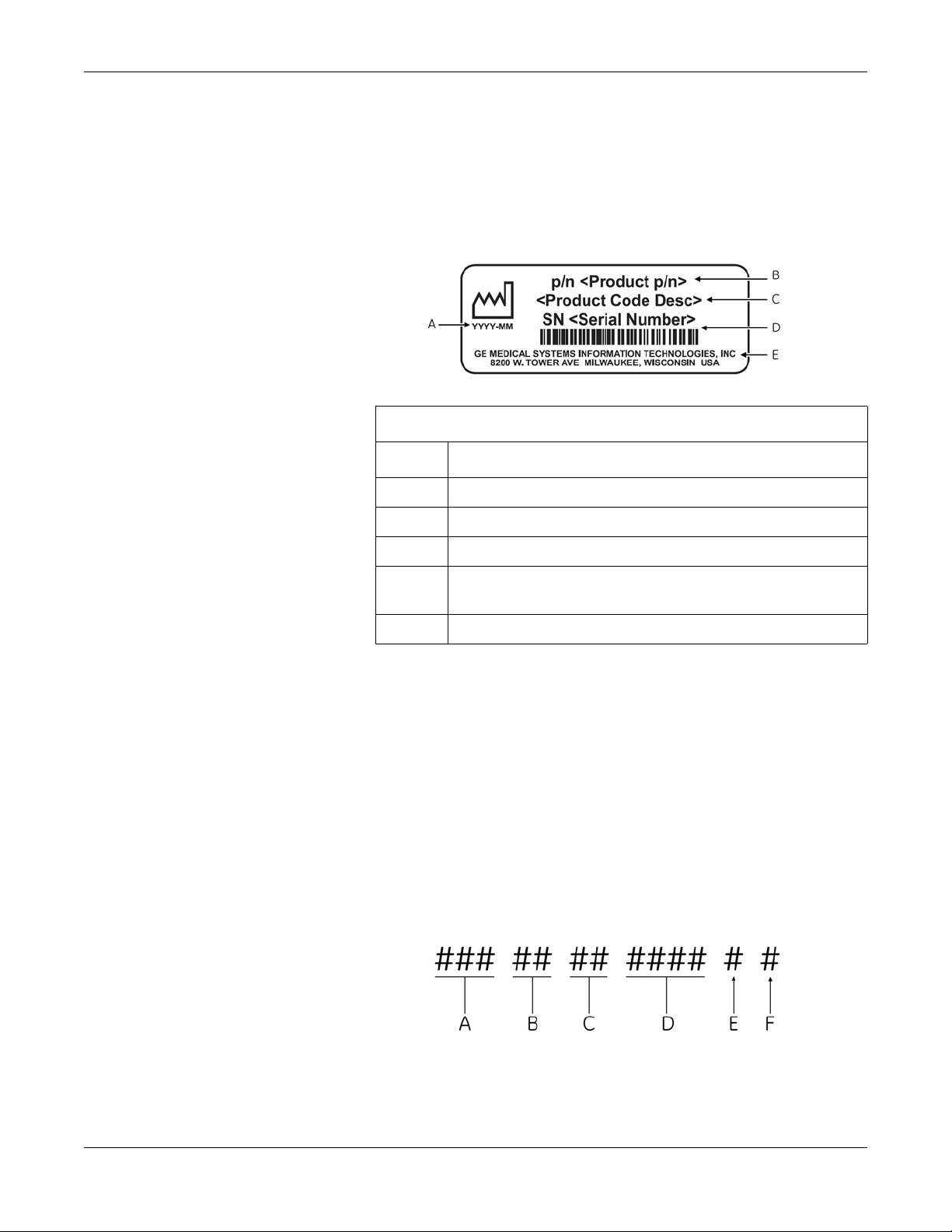
GE product labels provide the product’s part number, model description,
serial number, manufacture date, and manufacture site. The following
illustration shows the layout of a typical product label. A description of
the label components follows the illustration.
Product Label
Item Description
A Date of manufacture in YYYY-MM format
Serial Number Format
B Part number of product
C Product code description
D Serial number.
For more information, see “Serial Number Format” on page 1-5.
E Manufacture site
NOTE
Actual product label may differ from this representative example.
Every GE device is uniquely identified via serial number, which appears
on the product label (see “Product Label Format” on page 1-5). The
following illustration and table describe the serial number components.
2031504-159B MAC™ 800 1-5
Page 12

Introduction
Service Requirements
A The product code for MAC 800 systems is SDS.
B Year Manufactured (00-99). Examples:
07 = 2007
08 = 2008
C Fiscal Week Manufactured
D Production Sequence Number
E Manufacturing Site
F Miscellaneous Characteristic
Refer equipment servicing to GE-authorized service personnel only. Any
unauthorized attempt to repair equipment under warranty voids the
warranty.
It is the user’s responsibility to report the need for service to GE or to
one of their authorized agents.
1-6 MAC™ 800 2031504-159B
Page 13

2 Equipment Overview
2031504-159B MAC™ 800 2-1
Page 14
Equipment Overview
General Description
The MAC™ 800 is a 3- and 6-lead print, 12-channel display system with
a 7 inch (17.78 cm) diagonal display, active patient cable, battery
operation, and options for communication capabilities.
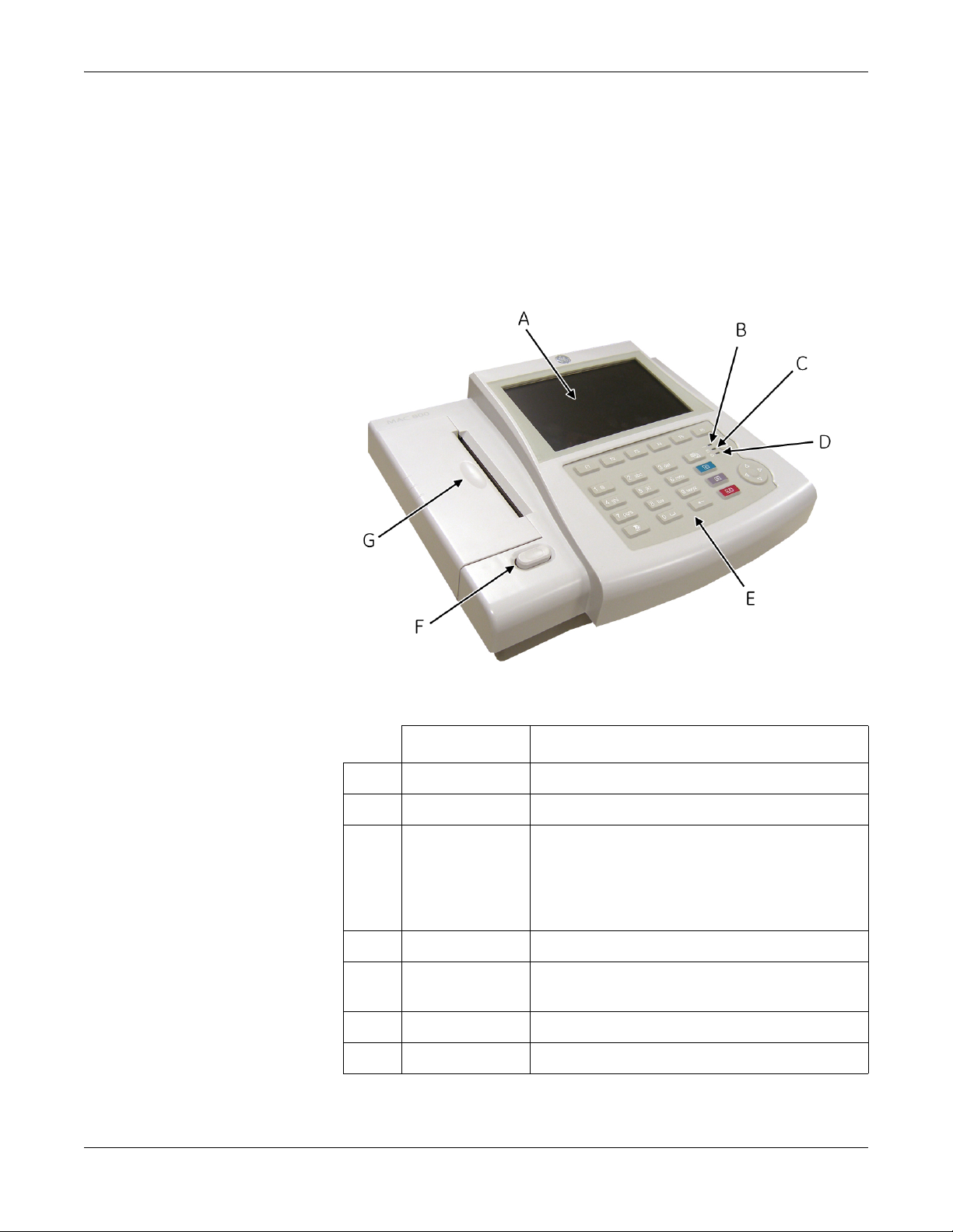
Front View
Name Description
A Screen Displays waveform and text data.
B AC LED Indicates when the unit is connected to AC power.
C Battery LED Indicates current battery status.
Solid indicates the battery is charging.
Flashing indicates the battery is low.
Off indicates the battery is fully-charged or is
discharging but not at a low state.
D Power LED Indicates when the unit is powered on.
E Keypad Controls the system or enters data. See “Keypad” on
page 2-4 for more information.
F Writer Door Button Opens printer door.
G Writer Prints reports.
2-2 MAC™ 800 2031504-159B
Page 15

Side View
Equipment Overview
Name Description
A ECG signal input connector Connects the patient cable to the device.
Back View
B Secure digital (SD) card
slot
Houses the secure digital (SD) card for external
storage.
Name Description
A Modem port Standard RJ-11 jack for connecting the modem to
a telephone line.
2031504-159B MAC™ 800 2-3
Page 16
Equipment Overview
Keypad
Name Description
B LAN port Standard RJ-45 jack for connecting the device to a
LAN. LEDs on the port indicate status.
Solid green indicates a good connection.
Flashing amber indicates network traffic.
C USB port Universal Serial Bus port used to connect external
devices, such as the optional barcode reader.
D COMM port Serial port for data communication. Use a serial
cable to connect the unit to a CASE/Cardiosoft or
MUSE system.
E Main AC power connector Connects the unit to an AC power outlet.
F Equipotential grounding lug Grounded connector for attaching non-grounded
peripheral devices to ensure equipotentiality.
G Carry handle Retractable handle for carrying the unit.
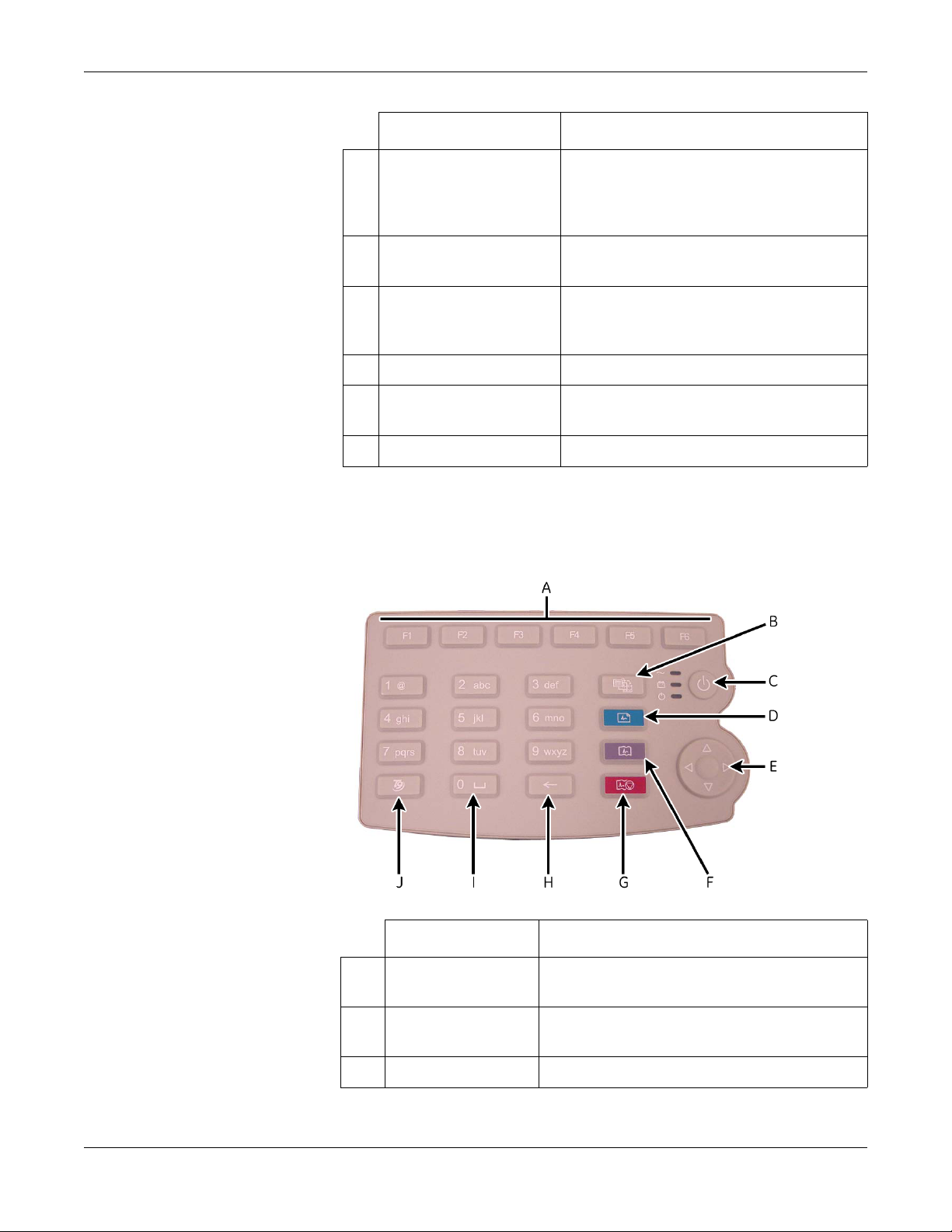
The English keypad is shown in the following illustration.
Name Description
A Function Keys
(F1 through F6)
Selects menu options on the screen.
B Leads key Changes the leads when the screen is being used to
display waveforms.
C Power Button Turns the unit on and off.
2-4 MAC™ 800 2031504-159B
Page 17

Equipment Overview
Name Description
D ECG key Acquires a resting ECG and prints a 10-second report
in Arrhythmia mode.
E Trimpad The arrows move the cursor left, right, up, or down.
The center button moves the focus within a window or
selects the currently active item.
F Rhythm key Prints a continuous, real-time rhythm ECG strip. Press
the Stop key to stop the rhythm strip from printing.
G Stop key Stops the writer from printing.
H Backspace Key Deletes characters.
I Space Key Adds a space between typed characters.
J T9 key Switches between different input methods. For more
information on using the T9 key, refer to the MAC™
800 Operator’s Manual.
2031504-159B MAC™ 800 2-5
Page 18
Equipment Overview
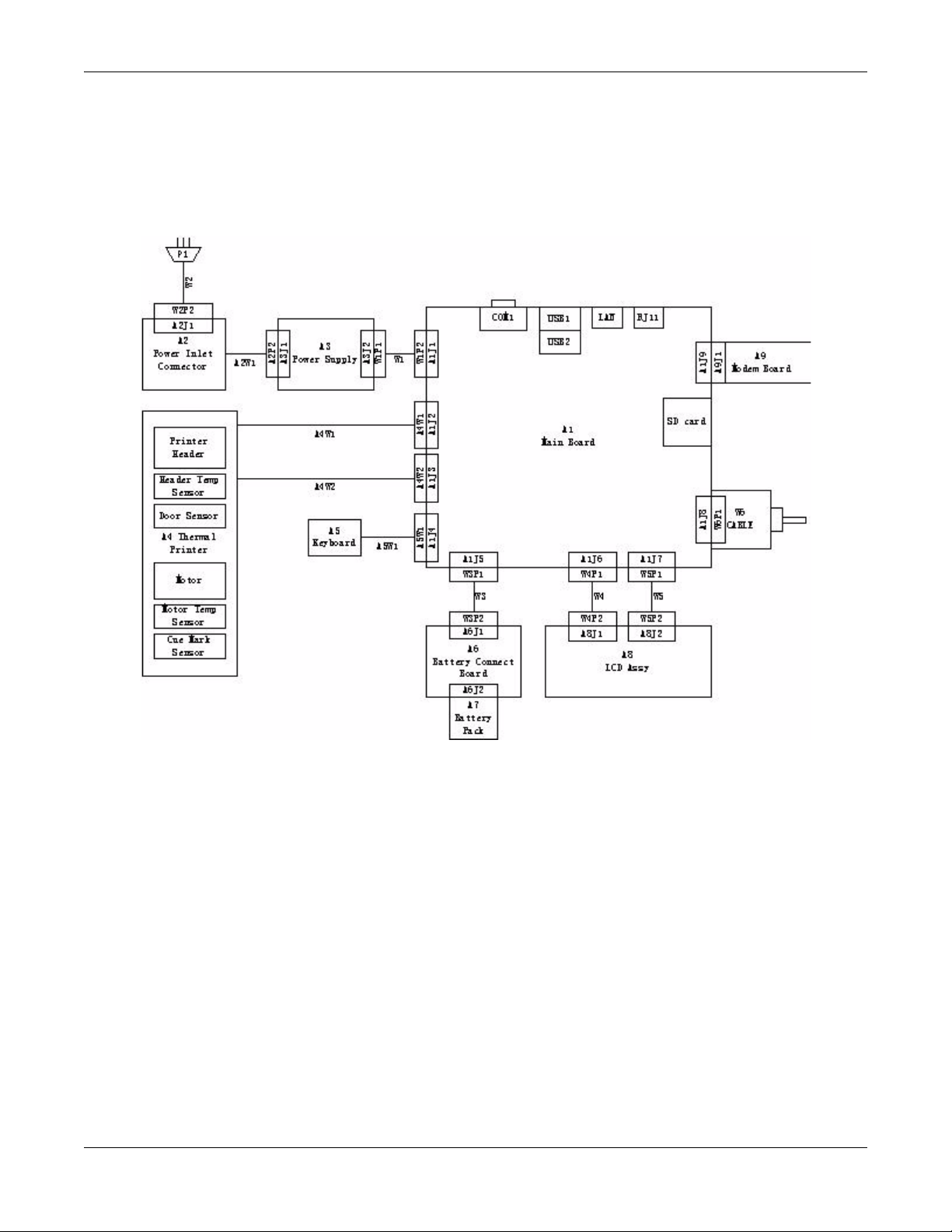
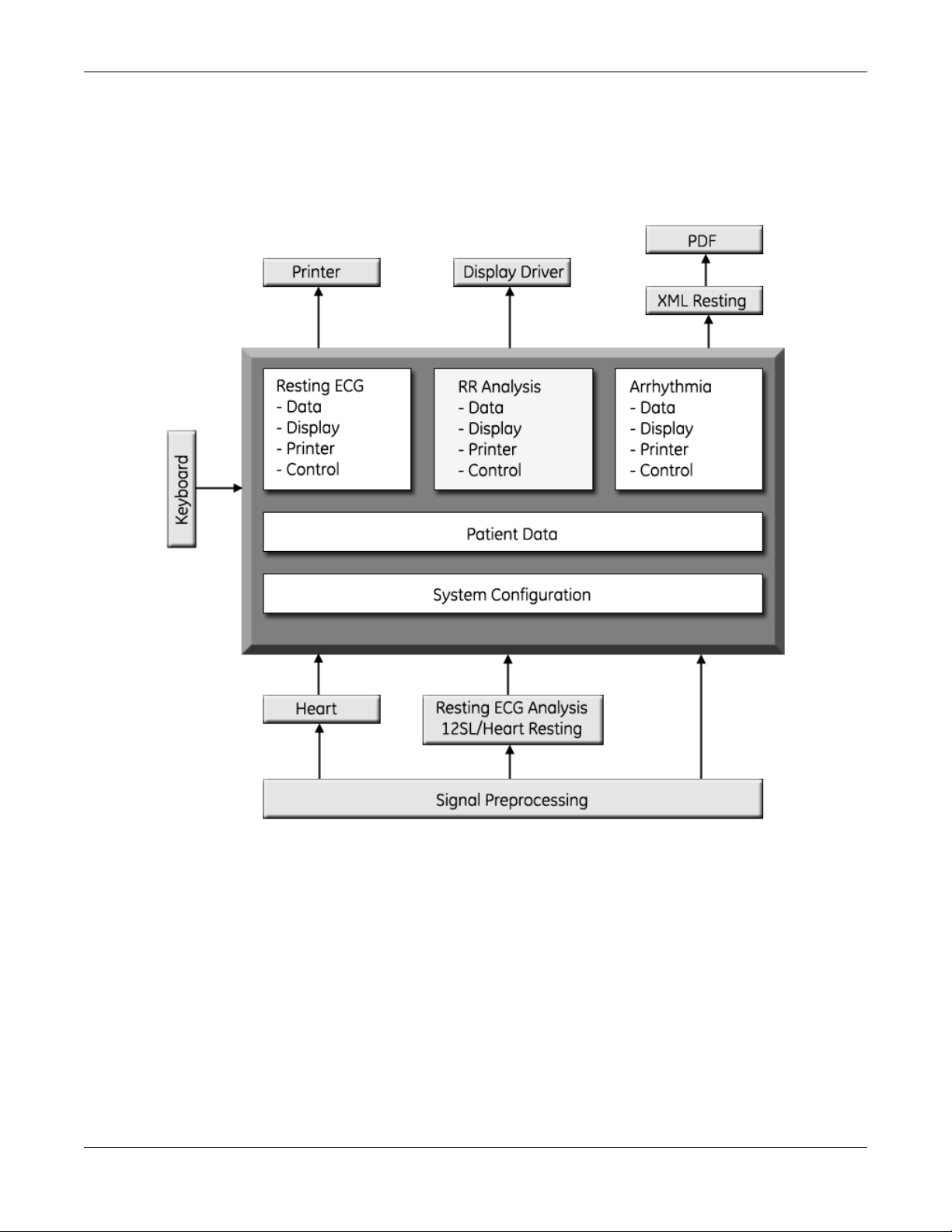
Detailed Description
Block Diagram
2-6 MAC™ 800 2031504-159B
Page 19

System Architecture
Overview
Equipment Overview
2031504-159B MAC™ 800 2-7
Page 20

Equipment Overview
Hardware/firmware Architecture
The MAC 800 hardware and firmware subsystems include the following:
Hardware Subsystems Firmware Subsystems
Product Interfaces
CPU core
Display
Keyboard
ECG Acquisition subsystem
Thermal printer
Power supply
Housing
CE BSP (Board-Support-Package)
Printer API
Printer SW (Firmware for the Printer)
Acquisition API
Acquisition SW (Firmware for the Printer)
The MAC 800 system offers the following interfaces for connecting to
external devices for data communication, software updates, and the
control of workload devices:
RS232 port (1)
Connects to external systems, like MUSE or Cardiosoft.
RJ-45 port (1)
Connects to networks via 100baseT ethernet connector via an
external medical isolator.
USB connector(2)
Connects to USB-capable devices, such as optional barcode reader or
external USB keyboard.
Secure Digital (SD) Card slot
Interfaces with a Secure Digital card, which is used to store ECGs, to
flash the device with software updates, and to connect memory /
future IO extensions.
RJ-11 port (1)
Connects an internal medical grade Analog Modem (optional) to a
phone line.
2-8 MAC™ 800 2031504-159B
Page 21
Software Architecture
Layered Structure of application software
Equipment Overview
2031504-159B MAC™ 800 2-9
Page 22
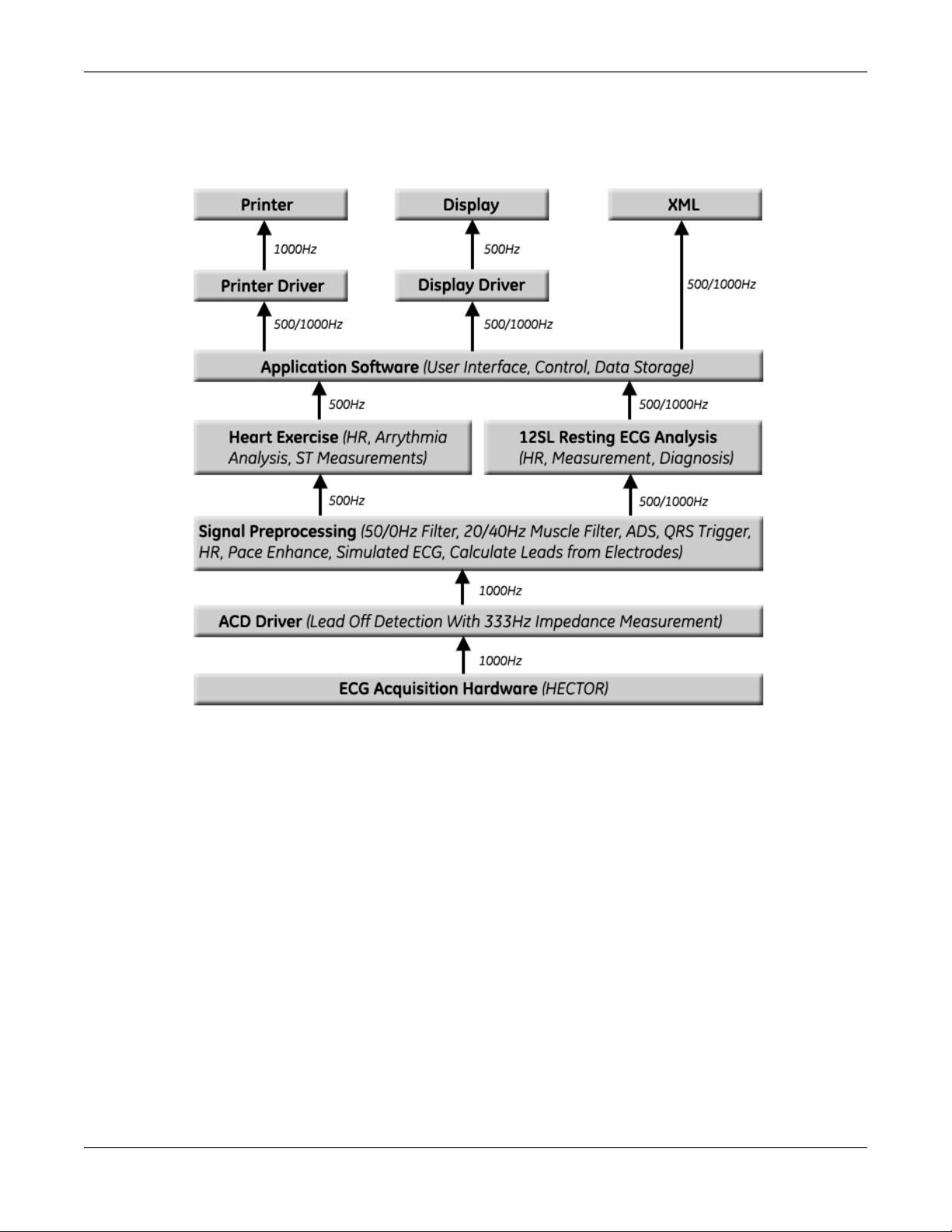
Equipment Overview
ECG Data Flow With Sampling Rates
2-10 MAC™ 800 2031504-159B
Page 23

3 Troubleshooting
2031504-159B MAC™ 800 3-1
Page 24

Troubleshooting
General Fault Isolation
Power-Up Self-Test
See the MAC™ 800 Operator’s Manual, Chapter 2, “Equipment
Overview: Getting Started” to verify operation.
On power-up, the system automatically runs an internal self-test. If all
circuit tests pass, you will see the start-up screen.
Poor Quality ECGs
The next screen that appears after the start-up screen depends on the
Power Up mode selected in System Configuration. The Resting ECG
mode is the default Power Up mode.
If the equipment is not working properly, ask the following questions.
Is the unit turned on?
Have there been any changes in the use, location, or environment of
the equipment that could cause the failure?
Has the equipment hardware or software been modified since last
use?
Is operator error the cause of the problem?
Try to repeat the scenario exactly and compare that to the proper
operation of the equipment described in the manual.
Is the battery installed?
When connected to the AC wall outlet, does the green AC power light
glow?
Poor quality ECGs can be caused by factors in the environment,
inadequate patient preparation, hardware failures related to the
acquisition module, lead wires, cables, or problems in the unit.
3-2 MAC™ 800 2031504-159B
Page 25

Visual Inspection
Troubleshooting
A thorough visual inspection of the equipment can save time. Small
things—disconnected cables, foreign debris on circuit boards, missing
hardware, loose components—can frequently cause symptoms and
equipment failures that may appear to be unrelated and difficult to
track.
NOTE
Take the time to make all the recommended visual checks before
starting any detailed troubleshooting procedures
If the area is… Look for…
I/O Connectors and Cables
AC power cord
Interface cables
Circuit boards
Fraying or other damage
Bent prongs or pins
Cracked housing
Loose screws in plugs
Excessive tension or wear
Loose connection
Strain reliefs out of place
Moisture, dust, or debris (top and bottom)
Loose or missing components
Burn damage or smell of over-heated components
Socketed components not firmly seated
PCB not seated properly in edge connectors
Solder problems: cracks, splashes on board, incomplete
feedthrough, prior modifications or repairs
Ground wires/Wiring
Loose wires or ground strap connections
Faulty wiring
Wires pinched or in vulnerable position
Fasteners Loose or missing screws or other hardware, especially
fasteners used as connections to ground planes on PCBs
Power source
Faulty wiring, especially AC outlet
Circuit not dedicated to system
NOTE
Power source problems can cause static discharge,
reading problems, and discharge.
Keyboard
Cuts or cracks in the keyboard membrane
Unreadable labels
LCD display filter Scratches or cracks in the display filter (transparent part of
keyboard bezel) that impair viewing
Battery pack
SD card
2031504-159B MAC™ 800 3-3
Cracks, swells, or leaks in the battery casing
Dirt, scratches, or debris on contacts
Cracks
Dirt, scratches, or debris on contacts
Page 26
Troubleshooting
Event Logging
Setting Up Event Logging
The MAC 800 system can be set up to create an XML-format Event Log
that contains system errors, warnings, and informational messages. Use
the following procedure to configure the level of severity of messages
written to the Event Log.
1. Power on the MAC 800 system by pressing the Power button.
2. From the Main Menu, press F4 to select System Configuration.
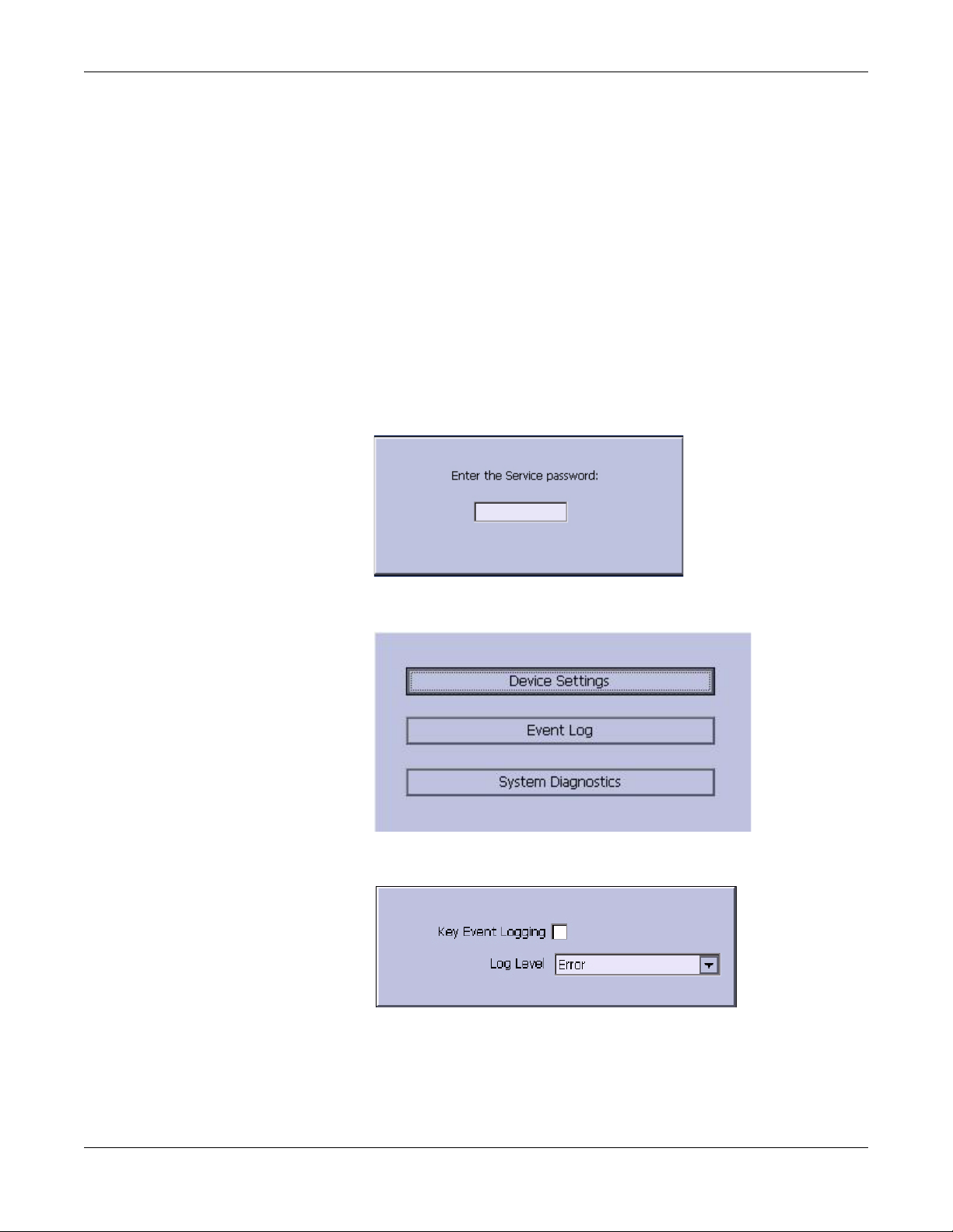
3. Press F6 (More) > F6 (More) > F5 (Service Setup).
The following window prompts you to enter the Service password.
4. Type 7763 and press F6 to select OK to open the Service Setup menu.
5. Move the focus to the Event Log button and press the Enter key.
6. Do one of the following:
To enable event logging, check the Key Event Logging check box.
To disable event logging, clear the Key Event Logging check box.
3-4 MAC™ 800 2031504-159B
Page 27

7. Select a level of severity to log from the Log Level list:
8. Press F6 to select Save.
Exporting the Event Log
1. Repeat step 1 through step 5 in “Setting Up Event Logging” on
2. Insert an SD card (gold contacts down) into the SD card slot as
Troubleshooting
Select None to log nothing to the Event Log.
Select Error to log only errors to the Event Log.
Select Warning to log errors and warnings to the Event Log.
Select Information to log errors, warnings, and information
messages to the Event Log.
page 3-4.
shown in the following illustration.
3. Press F1 to select Export Log Files.
The current Event Log file, log_0.log, is copied to a log directory on
the SD card.
NOTE
To access the log file, insert the SD card into an SD card reader
connected to a computer with a Windows operating system and open
the log file with a text editor like Notepad or WordPad. If the Event
Log is requested by GE Service for troubleshooting an issue, the file
can be sent as an email attachment.
Performing Diagnostic Tests
Diagnostic tests can be used to verify that the MAC™ 800 operates
properly. The tests check the operation of the display screen, speaker,
keyboard, thermal writer, battery, and communications. They are useful
tools for troubleshooting problems and can be useful as a part of system
checkout procedures.
2031504-159B MAC™ 800 3-5
Page 28
Troubleshooting
Accessing the System Diagnostics Function
The System Diagnostics menu can be used to perform functional
diagnostic tests. Use the following procedure to access the System
Diagnostics menu.
1. Power on the MAC 800 system by pressing the Power button.
2. From the Main Menu, press F4 to select System Configuration.
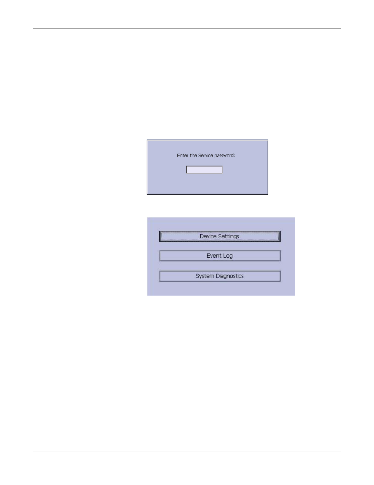
3. Press F6 (More) > F6 (More) > F5 (Service Setup).
The following window prompts you to enter the Service password.
4. Type 7763 and press F6 to select OK to open the Service Setup menu.
5. Move the focus to the System Diagnostics button and press the Enter
key to open the Diagnostic Tests window.
3-6 MAC™ 800 2031504-159B
Page 29

Display Test
Troubleshooting
The following sections describe how to perform the specific diagnostic
tests. Proceed to the appropriate section for the test you need to perform.
The Display Test can be used to determine if the display pixels are
working properly.
1. Open the Diagnostic Tests window as described in “Accessing the
System Diagnostics Function” on page 3-6.
2. Select the Display Test button.
The following window opens.
3. Select the Start Test button.
The following window opens.
2031504-159B MAC™ 800 3-7
Page 30

Troubleshooting
4. Press the right arrow key on the Trimpad repeatedly to move the
color bars horizontally across the screen.
5. Verify that the color band pattern (red, green, blue, white) scrolls
across the screen.
Pass the test if the pattern is replicated without discoloration.
6. Press the F1 key to switch to horizontal color bars.
7. Press the down arrow key on the Trimpad repeatedly.
8. Verify that the color band pattern (red, green, blue, white) scrolls
down the screen.
Pass the test if the pattern is replicated without discoloration.
9. Press the F1 key to switch to cycle through the solid color pane (red,
green, blue, white).
For each pane, check for black pixels. Pass the test if no more than
four black pixels are observed on any single color pane.
NOTE
A black pixel observed on one pane will probably be observed on
every pane.
10. Press Enter when the test is complete.
The following window opens.
3-8 MAC™ 800 2031504-159B
Page 31

Speaker Test
Troubleshooting
11. Select Pass or Fail:
If the test passed, press F4 to select Yes.
If the test failed, press F5 to select No.
Replace the display assembly as described in “Replacing the LCD
Assembly” on page 4-11.
The Speaker Test can be used to determine if the speaker is working
properly.
1. Open the Diagnostic Tests window as described in “Accessing the
System Diagnostics Function” on page 3-6.
2. Select the Speaker Test button.
3. Listen for a brief audible tone coming from the speaker.
The following window opens.
Keyboard Test
4. Select Pass or Fail:
If you heard an audible tone, press F4 to select Yes.
If you did not hear an audible tone, press F5 to select No.
Replace the mainboard assembly as described in “Replacing the
Mainboard Assembly” on page 4-15.
The Keyboard Test can be used to determine if the keyboard is working
properly.
1. Open the Diagnostic Tests window as described in “Accessing the
System Diagnostics Function” on page 3-6.
2. Select the Keyboard Test button.
The following window opens.
2031504-159B MAC™ 800 3-9
Page 32

Troubleshooting
3. Press each key on the keyboard and verify the value appears in the
corresponding representation of that key on the screen.
A key passes the test if its value appears on the screen when the
corresponding key is pressed.
4. To test for “sticky keys”, continue to press keys and verify that the
screen representation of the key is refreshing with each subsequent
key press.
5. Press F1 > Stop when the test is complete.
6. Select Pass or Fail:
Acquisition Module Test
The Acquisition Module Test can be used to determine if the acquisition
board is working properly.
1. Open the Diagnostic Tests window as described in “Accessing the
A key passes if the key on the screen refreshing with each repeated
key press.
The following window opens.
If every key passes the tests, press F4 to select Yes.
If any key fails a test, press F5 to select No.
Replace the keyboard assembly as described in “Replacing the
Keypad Assembly” on page 4-10.
System Diagnostics Function” on page 3-6.
2. Select the Acquisition Module Test button.
The following window opens.
3-10 MAC™ 800 2031504-159B
Page 33

Battery Test
Troubleshooting
Passed
1
3. Note the test result and press F6 to select Cancel.
If the result of the Acquisition Module Test Result is Failed, replace
the mainboard assembly as described in “Replacing the Mainboard
Assembly” on page 4-15.
The Battery Test can be used to determine the status of the Lithium-Ion
battery.
1. Open the Diagnostic Tests window as described in “Accessing the
System Diagnostics Function” on page 3-6.
Writer Test
2. Select the Battery Test button.
The following window opens.
3. Note the battery status information and press F6 to select Cancel
and close the Battery Status window.
If the Battery Status was Failed, replace the battery as described in
“Replacing the Battery Assembly” on page 4-7.
The Writer Test can be used to determine if the writer is working
properly.
NOTE
Before performing the Writer Test, be sure that the correct thermal
paper is properly loaded in the writer tray. Refer to the MAC 800
Resting ECG Analysis System Operator’s Manual for instructions on
loading paper.
2031504-159B MAC™ 800 3-11
Page 34

Troubleshooting
1. Open the Diagnostic Tests window as described in “Accessing the
System Diagnostics Function” on page 3-6.
2. Select the Writer Test button.
The following window opens.
3. Perform the 50mm/s Speed Test.
a. Select the 50mm/s Speed Test button.
The writer prints the 50 mm/s speed test report.
b. When one page of the report has printed, press the Stop button.
The following window opens.
c. Examine the printed report.
The 50mm/s speed test passes if one cycle of the square wave
spans 50 mm on paper, measured from corner to corner of wave,
with allowable tolerance of 1.0 mm. If that criteria is not met, the
text fails.
d. Do one of the following:
If the test passed, press F4 to select Yes.
If the test failed, press F5 to select No.
4. Repeat the previous step for the other speed tests.
The pass-fail criteria for each of the remaining tests is as follows:
25mm/s Speed Test - If one cycle of the square wave spans 25
mm on paper, measured from corner to corner of wave, with
allowable tolerance of 0.5 mm, the test passes. If this criteria is
not met, the test fails.
5mm/s Speed Test - If one cycle of the square wave spans 5 mm
on paper, measured from corner to corner of wave, with allowable
tolerance of 0.25 mm, the test passes. If this criteria is not met,
the test fails.
3-12 MAC™ 800 2031504-159B
Page 35

Troubleshooting
5. Perform the Print Head Test.
a. Select the Print Head Test button.
The writer prints a 1-page print head test report.
b. Verify that there are no gaps in any of the lines printed.
Up to 5 mm of blank paper is allowable at the top and bottom of
the page.
When the page is done printing, the following window opens.
c. Do one of the following:
If there are no gaps in the lines on the printed report, press
F4 to select Yes.
If there are gaps in the lines on the printed report, press F5
to select No.
Replace the printer as described in “Replacing the Printer
Assembly” on page 4-12.
6. When all writer tests have been performed, press F6 to select Cancel
and close the window.
RS232 Test
The RS232 Test can be used to determine if the comm ports are working
properly.
1. Open the Diagnostic Tests window as described in “Accessing the
System Diagnostics Function” on page 3-6
2. Use a paper clip to short pins 2 and 3 in the COM port.
3. Select the RS232 Test button.
The following window opens.
2031504-159B MAC™ 800 3-13
Page 36

Troubleshooting
4. Perform the COM Port Loop Back test on COM 1.
a. With the focus on COM 1, press the Enter key.
The results of the COM Loop Back Test are displayed.
b. Note the results of the test.
If either test failed, replace the mainboard assembly as described
in “Replacing the Mainboard Assembly” on page 4-15.
5. When the test is complete, press F6 to Cancel and close the results
window.
LAN Test
The LAN Test can be used to test network connectivity.
1. Connect the MAC 800 device to an active LAN.
Ensure that the LAN is an active network. If you connect to an
inactive network tap, the test result may be a false negative.
2. Open the Diagnostic Tests window as described in “Accessing the
System Diagnostics Function” on page 3-6.
3. Select the LAN Test button.
The following window opens.
4. Press the Enter key to select the Test Network Connectivity button.
The Checking connectivity. Please wait. message is displayed. Then,
the results of test are displayed.
If the System Connected to Network message is displayed in the
window, the test passes.
3-14 MAC™ 800 2031504-159B
Page 37

Modem Test
Troubleshooting
If the Network Unavailable message is displayed in the window
and you are sure the device is connected to an active network, the
test fails.
Replace the mainboard assembly as described in “Replacing the
Mainboard Assembly” on page 4-15.
5. When the test is complete, press F6 to Cancel and close the results
window.
The Modem Test can be used to test the internal modem.
1. Connect the MAC 800 device to an active analog phone line.
Ensure that the phone line is active. If you connect to an
inactive phone line, the test result may be a false negative.
2. Open the Diagnostic Tests window as described in “Accessing the
System Diagnostics Function” on page 3-6.
3. Select the Modem Test button.
USB Test
The following window opens.
4. With the focus on the Internal Modem Test button press the Enter
key.
The Test in Progress. Please wait message is displayed.
Then the results of the test are displayed.
If the Passed message is displayed in the window, the test passes.
If the Failed message is displayed in the window, the test fails.
Replace the internal modem as described in “Replacing the
Internal Modem (option)” on page 4-18.
The USB Test can be used to test the USB port.
1. Open the Diagnostic Tests window as described in “Accessing the
System Diagnostics Function” on page 3-6.
2. Connect a USB keyboard to the USB port of the MAC 800 back panel.
3. Select the USB Test button.
The following window opens.
2031504-159B MAC™ 800 3-15
Page 38

Troubleshooting
4. Press any key on the USB keyboard and verify pass or fail:
If the character that appears in the Character Input field
matches the key you pressed, the test passed.
If the character does not match or no character appears in the
Character Input field, the test fails.
5. When the test is complete, press F6 to Cancel.
The following window opens.
Patient Lead Wire Test
6. Do one of the following:
If the test passed, press F4 to select Yes.
If the test failed, press F5 to select No.
Replace the mainboard assembly as described in “Replacing the
Mainboard Assembly” on page 4-15.
Test the patient leadwires as described in this section.
1. Open the Diagnostic Tests window as described in “Accessing the
System Diagnostics Function” on page 3-6.
2. Connect a patient cable with lead wires to the MAC 800 patient cable
connector.
3. Connect all leads to a patient simulator or shorting bar.
4. Select the Patient Lead Wire Check button.
The window shown below opens.
3-16 MAC™ 800 2031504-159B
Page 39

Troubleshooting
5. Press the Enter key to select the Start Test button.
For each lead wire, the test results are displayed.
If the Connected message is displayed, the lead wire passes the
test.
If the Disconnected message is displayed, the lead wire fails the
test.
6. Press F6 (Cancel) when the test is complete.
7. Replace every lead wire that failed the test.
8. Repeat the test.
If the lead wire still fails the test, replace the mainboard assembly as
described in “Replacing the Mainboard Assembly” on page 4-15.
Equipment Problems
ECG Data Noise
If the acquired ECG data displays unacceptable noise levels:
When troubleshooting noise or signal quality, be sure the problem
is not being caused by poor skin preparation, or placement and
condition of electrodes.
Careful skin preparation is the key to an interference-free ECG.
Signal quality is indicated using Hookup Advisor. Hookup Advisor
can be turned on or off in the ECG menu. Select Main Menu > System
Configuration > Resting ECG Setup > Page Down.
Check for defective or date-expired electrodes.
Check for defective, broken, or disconnected leadwires.
Run the Acquisition Module Tests in the Diagnostic menu and make
sure all lead wires pass the noise test.
Refer to “Acquisition Module Test” on page 3-10.
2031504-159B MAC™ 800 3-17
Page 40

Troubleshooting
Error Codes
No action is necessary for isolated error occurrences. However if the unit
is malfunctioning and any of the following error messages are repeating
and unrecoverable, replace the FRUs in the order as listed.
Acquisition Error Codes
If you repeatedly receive any of the following acquisition error codes,
replace the mainboard assembly as described in “Replacing the
Mainboard Assembly” on page 4-15.
Acquisition Error -1 General acquisition error
Acquisition Error Codes
Error Code Cause
Printer Error Codes
Acquisition Error 3 Sequence number error in 100ms ECG Packet
Acquisition Error 9 Acquisition self test error
If you repeatedly receive any of the following printer error codes, replace
the printer assembly as described in “Replacing the Printer Assembly” on
page 4-12.
Printer Error Codes
Error Codes Cause
Printer Internal Error 2 Printhead temperature is too hot or too cold to print
Printer Internal Error 3 Printer driver could not be opened
Printer Internal Error 4 Printer driver communication error
Printer Internal Error 5 Printer driver timeout error
Printer Internal Error 6 Printer driver miscellaneous error
Printer Internal Error 7 Undefined printer status was received
3-18 MAC™ 800 2031504-159B
Page 41

Frequently Asked Questions
Maintenance
NOTE
See the MAC™ 800 Operator’s Manual for complete System
Configuration information.
Save System Setups to SD Card
Q: How do I save changes I have made to the System Configuration?
A: Perform the following steps:
1. Insert the SD card into the SD card slot in right side as shown.
Troubleshooting
2. Push the SD card into the slot to seat it in place.
3. From the Main Menu, press F4 to select System Configuration.
4. Press F6 (More) > F6 (More) > F3 to select Export Setup.
5. Highlight the setup file you want to save to SD card from the list on
left side of the window.
6. Press F1 to select Export.
The following window opens.
2031504-159B MAC™ 800 3-19
Page 42

Troubleshooting
Storing ECGs
7. Press F6 to select OK.
8. Eject the SD card by pushing it in once.
Store it in a secure location.
Q: Why won't any of the ECGs I perform save to the SD card?
A: Check the following:
Is the SD card fully inserted into the drive?
Are you using 128 MB or greater SD cards?
Is the SD card write-protected?
Have you tried a new SD card?
Is your system set up to automatically save records?
If your system is not set up to automatically save records, did you
press Store?
Cleaning
Q: Should I clean the MAC 800?
A: Clean the exterior surfaces of all the equipment and peripheral
devices monthly, or more frequently if needed.
Use a clean, soft cloth and a mild dish-washer detergent diluted in
water.
Wring the excess water from the cloth.
Do NOT drip water or any liquid on the writer assembly, and avoid
contact with open vents, plugs, and connectors.
Dry the surfaces with a clean cloth or paper towel
Refer to the MAC™ 800 Operator’s Manual for details on cleaning the
MAC 800 system.
3-20 MAC™ 800 2031504-159B
Page 43

Battery Capacity
MAC Address
Troubleshooting
Q: What is the capacity of the battery?
A: We recommend that the MAC 800 be connected to AC power through
a wall outlet whenever it is not in use. However, if operating the device
without AC power, be aware that a fully-charged battery is capable of
printing approximately 1000 single page reports or 2 hours of continuous
operation (without printing).
Q: I need to provide the MAC address of the device to the network
administrator to enable the LAN communication option. How do I obtain
the MAC address?
A: Follow these steps to obtain the MAC address:
1. Open the Diagnostic Tests window as described in “Accessing the
System Diagnostics Function” on page 3-6.
2. Move the focus to the Service Report button and press the Enter key
to select.
Calibration
3. Find the MAC address on the printed service report.
Q: How do I calibrate the MAC 800 system?
A: When it becomes necessary, you can calibrate the MAC 800 system
using the following method:
1. Using a standardizing waveform generator, produce a 1.00 ± 0.01
-mV pulse signal with a rise-time no greater than 5ms and a width
no greater than 100ms.
2. Connect the pulse signal to all available channels and set the gain to
10 mm/mV.
3. Verify the display pulses have an amplitude within ± 5% of the
amplitude obtained when the 1.00 ± 0.01 -mV signal is applied.
4. Repeat the test for all fixed gain settings to verify the
standardization pulse correctly reflects the gain setting.
NOTE
The error must be less than ±5% of the expected value or 0.5mm,
whichever is greater.
5. Verify that the standardization signal appears on all channels.
2031504-159B MAC™ 800 3-21
Page 44
Troubleshooting
System Setup
Location Number
Q: When entering patient data, how do I get the Location field to
automatically populate with the same number?
A: The Location number can be set in Basic Setup to save you from
entering it for each test.
1. From the Main Menu, press F4 to select System Configuration.
2. Press F1 to select Basic Setup.
3. Move the focus to the Location field.
4. Type the desired Location number.
5. Press F6 to select Save.
6. Press F5 to select Main Menu.
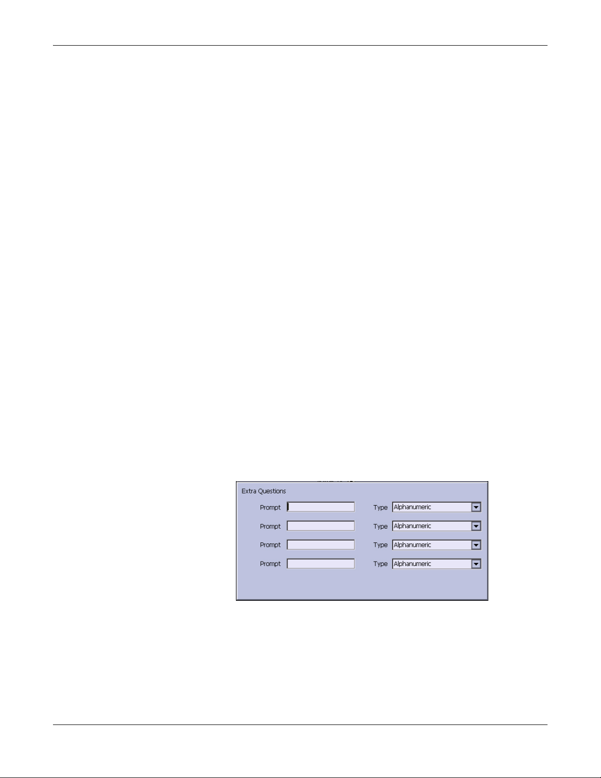
Patient Questions
Q: How do I change which questions I see when I am entering the
patient data?
A: The patient questions you see on the Patient Data window when
starting a test were set up in Patient Setup.
1. From the Main Menu, press F4 to select System Configuration.
2. Press F6 (More) > F4 (Patient Setup) > F4 to select Page Down.
3. Move the focus to the Extra Questions... button and press Enter to
open the Extra Questions window.
4. For each extra question you wish to ask in the Patient Data window,
type the Prompt and select the type of question from the Type list
(Alphanumeric, Numeric, Yes/No/Unknown).
5. Press F6 to select Save in the Extra Questions window.
6. Press F6 to select Save in the Test Information Setup window.
7. Return to the Main Menu.
3-22 MAC™ 800 2031504-159B
Page 45

Passwords
Serial Number
Troubleshooting
Q: The system was set up for High Security Mode and I forgot my
password. How do I access the system?
A: Use the following steps:
1. Contact GE Tech Support and provide the serial number of the
device you want to access.
They will generate a temporary, device-specific name and password
that can only be used for 24 hours.
2. Log into the system with the password provided by GE Tech Support.
3. Immediately after logging into the system, verify your MAC 800 user
name and password. Record this information and store in a secure
location for future reference.
Q: When the mainboard is replaced, how do I reenter the serial number
to the new mainboard?
A: Use the following steps:
1. From the Main Menu, select F4 (System Configuration) > F6 (More)
2. Type 7763 and press Enter.
3. Move the focus to Device Settings and press Enter.
4. Enter the unit’s serial number and press Enter.
Clinical
Resting ECG Report Format
Q: How do I change the way an ECG looks (format) when it prints out?
> F6 (More) > F5 (Service).
The system prompts for the service password.
The service window opens.
The Device Settings window opens.
The unit’s serial number is located on the product label on the bottom
of the device.
A: Do the following.
1. From the Main Menu, press F4 to select System Configuration.
2. Press F2 to select Resting ECG Setup.
3. Press F4 (Page Down) three times.
2031504-159B MAC™ 800 3-23
Page 46

Troubleshooting
4. Select which type of ECG report you want to change from 10s ECG
5. Select the number of copies you want from Report Copies list.
6. If you want the MAC 800 or 12SL Interpretation included on the
7. If you do not want the MAC 800 interpretation to print on the ECG,
8. Press F6 to save the setup.
Editing
Q: Can you edit the interpretation at the MAC 800, and then transmit
the edited record to the MUSE system as an unconfirmed record?
A: MAC 800 does not support edit interpretation.
Navigating the User Interface
Report Format list:
ECG, check the Print Interpretation check box.
clear the Print Interpretation check box.
Q: How do I navigate from the startup screen to the Main Menu?
A: The MAC 800 system can be configured in a number of different
ways. Some of these configuration choices determine the actions that
need to be performed in order to proceed from the power up display to the
Main Menu.
There are three configurations that determine the initial window that
appears at power up and what actions the user will need to perform to
navigate to the Main Menu.
Power Up mode currently selected in Basic Setup:
High Security mode enabled in Basic Setup:
USB Barcode Reader support option activated - yes or no.
3-24 MAC™ 800 2031504-159B
Page 47

Troubleshooting
The various steps in this section describe how to navigate from the power
up screen to the Main Menu for the various system configurations.
Use the steps that apply to your system configuration settings.
If your system is configured to power up in the Resting ECG mode,
go to “Resting ECG Power Up Mode” on page 3-25.
If your system is configured to power up in the Arrhythmia mode,
go to “Arrhythmia Mode Power Up Mode” on page 3-26.
If your system is configured to power up in the Main Screen mode,
go to “Main Screen Power Up Mode” on page 3-26.
Resting ECG Power Up Mode
These steps describe how to navigate to the Main Menu after powering
on the MAC 800 system when Resting ECG is selected for Power Up
mode in Basic Setup.
NOTE
1. If the High Security Mode is enabled, proceed with step a through
2. Press F5 to select Cancel.
3. Press F6 to select More.
To perform system setup functions, log in as a user who is assigned
setup editing privileges.
step d when prompted for a User ID and Password; if the password
prompt does not appear, go to step 2.
a. Type your user ID in the User ID field.
b. Press the Enter key or press the down arrow key on the
trimpad to move the focus to the Password field.
c. Type your password in the Password field.
d. Press the F5 key to select Login.
4. Press F5 to select Main Menu.
2031504-159B MAC™ 800 3-25
Page 48

Troubleshooting
Arrhythmia Mode Power Up Mode
These steps describe how to navigate to the Main Menu after powering
on the MAC 800 system when Arrhythmia is selected for Power Up mode
in Basic Setup.
NOTE
To perform system setup functions, log in as a user who is assigned
setup editing privileges.
1. If the High Security Mode is enabled, proceed with step a through
step d when prompted for a User ID and Password; if the password
prompt does not appear, go to step 2.
a. Type your user ID in the User ID field.
b. Press the Enter key or press the down arrow key on the
c. Type your password in the Password field.
d. Press the F5 key to select Login.
trimpad to move the focus to the Password field.
If the barcode reader option is enabled, a window opens
prompting you to scan the patient barcode.
2. Press F6 to select Cancel.
3. Press F5 to select Cancel.
4. Press F6 to select More.
5. Press F5 to select Main Menu.
Main Screen Power Up Mode
These steps describe how to navigate to the Main Menu after powering
on the MAC 800 system when Main Screen is selected for Power up mode
in Basic Setup.
NOTE
1. If the High Security Mode is enabled, proceed with step a through
NOTE
If the barcode prompt does not appear, go to step 3.
To perform system setup functions, log in as a user who is assigned
setup editing privileges.
step d when prompted for a User ID and Password; if the password
prompt does not appear, go to step 2.
a. Type your user ID in the User ID field.
b. Press the Enter key or press the down arrow key on the
trimpad to move the focus to the Password field.
c. Type your password in the Password field.
d. Press the F5 key to select Login.
3-26 MAC™ 800 2031504-159B
Page 49

Troubleshooting
The Main Menu is displayed.
2. If the system is configured for Main Screen Power up mode and does
not have the High Security Mode enabled, the Main Menu appears
after powering up the system. No further keys need be pressed in
order to display the Main Menu.
2031504-159B MAC™ 800 3-27
Page 50

Troubleshooting
3-28 MAC™ 800 2031504-159B
Page 51

4 Maintenance
2031504-159B MAC™ 800 4-1
Page 52

Maintenance
Introduction
Recommended Maintenance
Regular maintenance, irrespective of usage, is essential to ensure that
the equipment will always be functional when required. See the MAC
800 Resting ECG Analysis System Operator’s Manual for cleaning
procedures. GE recommends that electrical safety checks be performed
annually.
WARNING
MAINTENANCE RESPONSIBILITIES — Failure on the
part of all responsible individuals, hospitals or
institutions employing the use of this device to implement
the recommended maintenance schedule may cause
equipment failure and possible health hazards. The
manufacturer does not, in any manner, assume the
responsibility for performing the recommended
maintenance schedule, unless an Equipment
Maintenance Agreement exists.
The sole responsibility for performing the recommended
maintenance schedule rests with the individuals,
hospitals, or institutions utilizing the device.
Required Tools and Supplies
The following list identifies the tools required to perform the procedures
described in this chapter.
ECG simulator
Phillips #1 screwdriver
Hexagonal screw drivers
Current leakage tester
Anti-static wrist strap
MAC™ 800 Service Manual
MAC™ 800 Operator’s Manual
NOTE
Always use an anti-static wrist strap while opening the MAC 800
unit to avoid possible damage due to static electricity.
4-2 MAC™ 800 2031504-159B
Page 53

High-Level FRU Identification
Top Cover Assembly
Bottom Assembly
Maintenance
Battery
LCD Assembly
2031504-159B MAC™ 800 4-3
Page 54

Maintenance
Mainboard (A) and
Internal Modem (B, option)
Power Supply Assembly
Writer Assembly
Keypad Assembly
Barcode Reader (option)
4-4 MAC™ 800 2031504-159B
Page 55

Patient Cable
Serial Cable
FRU Replacement Procedures
Maintenance
Preparing System for FRU Replacement
Prior to performing any disassembly procedures, perform these steps.
NOTE
Take strict precautions against electrostatic discharge damage
while replacing field replaceable units.
1. Power off the system.
2. Disconnect the unit from the AC wall outlet.
3. Disconnect the power cord from the back panel connector.
4. Disconnect the patient cable from the unit as described in “Replacing
the Patient Cable” on page 4-5.
5. Remove the battery as described in “Replacing the Battery
Assembly” on page 4-7.
Replacing the Patient Cable
1. Disconnect the system from AC power.
2. Disconnect the patient cable from the MAC 800 side panel connector
as shown in the following illustration.
2031504-159B MAC™ 800 4-5
Page 56

Maintenance
3. Connect the new patient cable to the side panel connector.
4. Perform the applicable checkout procedures.
Refer to “Functional Checkout” on page 4-23.
Replacing Barcode Reader
1. Power off the system and disconnect from AC power.
2. Disconnect the barcode reader from the USB connector on the
MAC 800 rear panel as shown in the following illustration.
3. If only the cable is to be replaced, disconnect the cable from the
barcode reader using the following instructions.
a. Insert an Allen wrench (or straightened paper clip) in the
small hole in the base of the barcode reader.
4-6 MAC™ 800 2031504-159B
Page 57

Maintenance
b. While pushing the tool into the hole, pull the cable to remove it
from the base of the barcode reader.
4. With a new cable, reverse the disassembly procedures to reassemble.
Insert USB connector with (the USB symbol) facing down.
5. Configure the new barcode reader as described in the MAC™ 800
Operator’s Manual.
6. Perform the applicable checkout procedures.
Refer to “Functional Checkout” on page 4-23.
Replacing the Battery Assembly
1. Disconnect the system from AC power.
2. Turn the unit over.
3. Press the battery release tab (A) and raise the battery from its
compartment to remove it.
4. Insert the new battery by reversing the steps for removal.
5. Perform the applicable checkout procedures.
Refer to “Functional Checkout” on page 4-23.
2031504-159B MAC™ 800 4-7
Page 58

Maintenance
Replacing the Top Cover Assembly
1. Disconnect the system from AC power.
2. Remove the battery assembly as described in “Replacing the Battery
Assembly” on page 4-7
3. Remove the six screws from the bottom of the device.
4. Turn the unit right side up.
5. Press the printer button.
6. Open the printer door.
7. Lift the top assembly approximately 1 inch at the back panel side.
4-8 MAC™ 800 2031504-159B
Page 59

Maintenance
8. Pull up the lock-release tab on mainboard keypad connector.
9. Disconnect the keypad cable as shown.
2031504-159B MAC™ 800 4-9
Page 60

Maintenance
10. Remove the eight screws from the bottom of the top cover assembly.
11. Separate the keypad from the top cover assembly.
12. Reassemble a new top cover assembly by reversing the steps for
removal.
13. Perform the applicable checkout procedures.
Refer to “Functional Checkout” on page 4-23.
Replacing the Keypad Assembly
1. Perform step 1 to step 11 as described in “Replacing the Top Cover
Assembly” on page 4-8.
2. Reassemble a new keypad assembly by reversing the steps for
removal.
3. Perform the applicable checkout procedures.
Refer to “Functional Checkout” on page 4-23.
4-10 MAC™ 800 2031504-159B
Page 61

Replacing the LCD Assembly
1. Disconnect the system from AC power.
2. Remove the battery assembly as described in “Replacing the Battery
Assembly” on page 4-7.
3. Remove the top cover assembly as described in “Replacing the Top
Cover Assembly” on page 4-8.
4. Remove the two screws that hold the LCD assembly in place.
Maintenance
5. Push the LCD assembly forward to away from the rear panel.
2031504-159B MAC™ 800 4-11
Page 62

Maintenance
6. Disconnect the inverter cable from the mainboard.
7. Disconnect the LCD cable from the mainboard.
8. Lift the LCD ASSY out of the BOTTOM ASSY.
9. Reassemble a new LCD ASSY by reversing the steps for removal.
10. Perform the applicable checkout procedures.
Refer to “Functional Checkout” on page 4-23.
Replacing the Printer Assembly
Removing the Printer Assembly
1. Disconnect the system from AC power.
2. Remove the battery assembly as described in “Replacing the Battery
Assembly” on page 4-7.
3. Remove the top cover assembly as described in “Replacing the Top
Cover Assembly” on page 4-8.
4. Remove the LCD Assembly as described in “Replacing the LCD
Assembly” on page 4-11.
4-12 MAC™ 800 2031504-159B
Page 63

Maintenance
5. Remove the printer door from the bottom cover assembly as shown.
6. Disconnect the printer cable from the mainboard.
7. Remove the two screws from the printer mounting base as shown.
2031504-159B MAC™ 800 4-13
Page 64

Maintenance
8. Remove the printer motor from the printer mounting base.
Reassembling the Printer Assembly
1. Replace a new printer motor on the bottom assembly as shown.
2. Replace the two mounting screws.
3. Reconnect the printer cable to the mainboard.
4. Replace the printer door.
5. Reassemble the LCD assembly.
6. Reassemble the top cover assembly.
7. Reassemble the battery assembly.
8. Perform the applicable checkout procedures.
Refer to “Functional Checkout” on page 4-23.
4-14 MAC™ 800 2031504-159B
Page 65

Replacing the Mainboard Assembly
Processing ECGs in Internal Storage
If the system has the internal storage option, process any ECGs
remaining in storage by transmitting to your archival system and/or
print them to ensure you have a printed record before proceeding with
the mainboard replacement.
Saving System Configuration Settings
1. Store the System Configuration settings to an SD card.
a. Insert SD card in the SD card slot.
b. From the Main Menu, press F4 to select System Configuration.
c. Press F6 (More) > F6 (More) > F3 to select Export Setup.
d. Highlight the system setup file you want to export to the SD
card.
Maintenance
e. Press F1 to select Export.
f. When the Configuration was successfully exported message is
displayed, press F6 to select OK.
g. Remove the SD card and store in a secure location.
2. Print the System Setup Report if you feel you may need it for
additional reference after the FRU replacement procedure.
a. From the Main Menu, press F4 to select System Configuration.
b. Press F6 (More) > F3 to select Print Setup Report.
c. Move the focus to the Complete Setup button and press Enter.
d. Save the printed setup report in a secure location. It can be used
as a reference if System Setup needs to be restored manually.
Removing the Mainboard Assembly
1. Disconnect the system from AC power.
2. Remove the battery assembly as described in “Replacing the Battery
Assembly” on page 4-7.
3. Remove the top cover assembly as described in “Replacing the Top
Cover Assembly” on page 4-8.
4. Remove the LCD assembly as described in “Replacing the LCD
Assembly” on page 4-11.
5. Disconnect the printer cable from the mainboard.
2031504-159B MAC™ 800 4-15
Page 66

Maintenance
6. Remove the 10 screws that hold the mainboard in place.
7. Lift the mainboard assembly approximately 1.5 inch.
8. Disconnect the battery cable from the bottom side of mainboard.
4-16 MAC™ 800 2031504-159B
Page 67

9. Disconnect the AD-DC cable from the bottom side of mainboard.
Reassembling the Mainboard Assembly
1. Reconnect the AC/DC cable to the bottom of the new mainboard.
2. Reconnect the battery cable to the bottom of the new mainboard.
Maintenance
3. Replace the new mainboard assembly on bottom cover assembly as
shown.
4. Replace the 10 screws that were removed in step 6 on page 4-16.
5. Reconnect the printer cable to the new mainboard.
6. Reassemble the LCD assembly.
7. Reassemble the top cover assembly.
8. Reassemble the battery assembly.
9. Connect the power cord to AC power.
10. Install the software from the SD card that shipped with the
mainboard and activate the options.
2031504-159B MAC™ 800 4-17
Page 68

Maintenance
11. Restore system setups that were saved to the SD card.
12. Perform the applicable checkout procedures.
Refer to “Functional Checkout” on page 4-23.
Replacing the Internal Modem (option)
1. Disconnect the system from AC power.
2. Remove the battery assembly as described in “Replacing the Battery
Assembly” on page 4-7.
3. Remove the top cover assembly as described in “Replacing the Top
Cover Assembly” on page 4-8.
4. Remove the lcd assembly as described in “Replacing the LCD
Assembly” on page 4-11.
5. Remove the internal modem from its socket.
6. Reassemble the internal modem by reversing the steps for removal.
Take care to align the contact pins with the sockets and align the
hole with the plastic pin before pushing it into the sockets.
7. Perform the applicable checkout procedures.
Refer to “Functional Checkout” on page 4-23.
Replacing the Power Supply Assembly
Removing the Power Supply Assembly
1. Disconnect the system from AC power.
2. Remove the battery assembly as described in “Replacing the Battery
Assembly” on page 4-7.
3. Remove the top cover assembly as described in “Replacing the Top
Cover Assembly” on page 4-8.
4. Remove the LCD assembly as described in “Replacing the LCD
Assembly” on page 4-11.
5. Remove the mainboard assembly as described in “Removing the
Mainboard Assembly” on page 4-15.
6. Remove the six M3X8 screws from the shield plate as shown in the
following illustration.
4-18 MAC™ 800 2031504-159B
Page 69

Maintenance
7. Remove the two M3X12 flat screws from the shield plate as shown in
the following illustration.
8. Remove the four hexagon screws from the shield plate as shown in
the following illustration.
2031504-159B MAC™ 800 4-19
Page 70

Maintenance
9. Remove the shield plate from the bottom cover assembly.
10. Remove the four hexagon screws of AC/DC as shown in the following
illustration.
11. Lift the AC/DC and disconnect the AC inlet cable as shown in the
following illustration.
4-20 MAC™ 800 2031504-159B
Page 71

Reassembling the Power Supply Assembly
1. Connect the AC inlet cable to the new AC/DC.
2. Place the new AC/DC in the bottom cover assembly.
3. Replace the four hexagon screws.
4. Route the AC/DC cable for mainboard as shown.
Maintenance
5. Replace the shield plate.
6. Replace the six M3X8 screws, two M3X12 flat screws, and four
hexagon screws on the shield plate.
7. Reassemble the mainboard assembly.
8. Reassemble the printer assembly.
9. Reassemble the LCD assembly.
10. Reassemble the top cover assembly.
11. Reassemble the battery assembly.
12. Perform the applicable checkout procedures.
Refer to “Functional Checkout” on page 4-23.
Replacing the Bottom Cover Assembly
1. Disconnect the system from AC power.
2. Remove the battery assembly as described in “Replacing the Battery
Assembly” on page 4-7.
3. Remove the top cover assembly as described in “Replacing the Top
Cover Assembly” on page 4-8.
4. Remove the LCD assembly as described in “Replacing the LCD
Assembly” on page 4-11.
2031504-159B MAC™ 800 4-21
Page 72

Maintenance
5. Remove the printer assembly as described in “Removing the Printer
Assembly” on page 4-12.
6. Remove the mainboard assembly as described in “Removing the
Mainboard Assembly” on page 4-15.
7. Remove the power supply assembly as described in “Replacing the
Power Supply Assembly” on page 4-18.
8. Replace the new bottom cover assembly.
9. Reassemble the power supply assembly.
10. Reassemble the mainboard assembly.
11. Reassemble the printer assembly.
12. Reassemble the LCD assembly.
13. Reassemble the top cover assembly.
14. Reassemble the battery assembly.
15. Perform the applicable checkout procedures.
Replacing the Fuse
Refer to “Functional Checkout” on page 4-23.
1. Disconnect the system from AC power.
2. Using a screw driver, take out the fuse holder from the AC inlet as
shown in the following illustration.
3. Replace two new fuse in the fuse holder.
4-22 MAC™ 800 2031504-159B
Page 73

4. Reassemble the fuse holder into AC inlet.
Functional Checkout
The checkout procedures apply to all MAC 800 systems.
NOTE
The FRU checkout procedure for any listed FRU also applies to its
internal PCBs and components.
Maintenance
Perform the applicable product or product configuration dependant
procedures when an asterisk (*) is listed.
FRU replacement procedures are contained within this chapter of
the manual.
Basic System FRU Repairs
FRU Description Visual Inspection
Patient Cable 1, 2, 7 1, 2, 3
Keypad Assembly 3, 6, 7 1, 2, 3, 7
Top Cover Assembly 6, 7 1, 2, 3, 14
LCD Assembly 3, 6, 7 1, 2, 3, 6
Printer Assembly 6, 7 1, 2, 3, 8
Mainboard Assembly 6, 7 1, 2, 3, 4, 5, 6, 7, 8, 9, 10,
Power Supply Assembly 6, 7 1, 2, 3
Bottom Cover Assembly 6, 7 1, 2, 3
Functional Checkout
Procedures
11, 12, 13
Battery Assembly 5 1, 2, 3, 11
AC Power Cord 4 1, 2, 3
Non Listed FRUs 6, 7
2031504-159B MAC™ 800 4-23
1, 2, 3, *14
1
Page 74

Maintenance
1
When AC Power Mains disturbed.
Optional System FRU Repairs
Visual Inspection
FRU Description Visual Inspection
Internal Modem 6, 7 1, 2, 3, 5, 13
Barcode Reader 6, 7 1, 2, 3
Non-FRU Repairs
FRU Description Visual Inspection
No parts replaced 4, 5, 6, 7 1, 2, 3, *4, 5
Software update n/a 1, 2, 3, *4, 5
Hardware upgrade 6, 7 1, 2, 3, *4, 5
Annual Electrical Safety
Checkout
1, 3, 4, 5 1, 2, 3, 6, 7, 8, 9, 10, 1 1, 12,
Functional Checkout
Procedures
Functional Checkout
Procedures
14, 13
Inspect the following for excessive wear and/or any visual signs of
damage.
1. Check for defective or broken patient cable/leadwires and out-of-date electrodes.
See “ECG Data Noise” on page 3-17 for more information.
2. Discuss electrode placement, skin prep, and patient-related requirements with the
ECG technician.
See Chapter 3, Preparing the Patient in the MAC 800 Operator’s Manual for more
information.
3. Verify the Keypad/LCD display filter passed inspection.
See “Visual Inspection” on page 3-3 for more information.
4. Verify the AC power cord passed inspection.
See “Visual Inspection” on page 3-3 for more information.
5. Verify the battery pack passed inspection.
See “Visual Inspection” on page 3-3 for more information.
6. Verify that all harnesses and internal wiring have been secured.
See “Visual Inspection” on page 3-3 for more information.
7. Verify the fasteners have been replaced and secured.
See “Visual Inspection” on page 3-3 for more information.
4-24 MAC™ 800 2031504-159B
Page 75

Functional Checkout Procedures
Perform the functional checkout procedures that are applicable to the
procedure that was performed.
Operational Checks
1. Verify the power-up self-test passed.
See “Power-Up Self-Test” on page 3-2 for more information.
2. Verify the rhythm strip recorded successfully.
See Chapter 5, “Recording a Resting ECG,” in the MAC™ 800 Operator’s
Manual.
3. Verify the ECG recorded successfully.
See Chapter 5, “Recording a Resting ECG,” in the MAC™ 800 Operator’s
Manual.
4. Verify the ECG was stored successfully.
See Chapter 8, “Managing Internal Storage,” in the MAC™ 800 Operator’s
Manual.
5. Verify that simulated ECG data was transmitted successfully to a receiving
product.
See Chapter 8, “Managing Internal Storage,” in the MAC™ 800 Operator’s
Manual.
Maintenance
Diagnostic Tests
6. Verify the display test was successful.
See “Display Test” on page 3-7 for more information.
7. Verify the keyboard test was successful.
See “Keyboard Test” on page 3-9 for more information.
8. Verify the writer test was successful.
See “Writer Test” on page3-11 for more information.
9. Verify the acquisition module test was successful.
See “Acquisition Module Test” on page 3-10 for more information.
10. Verify the patient leadwire check was successful.
See “Patient Lead Wire Test” on page 3-16 for more information.
11. Verify the battery test was successful.
See “Battery Test” on page 3-11 for more information.
12. Verify the LAN test was successful.
See “LAN Test” on page 3-14 for more information.
13. Verify the modem test was successful.
See “Modem Test” on page 3-15 for more information.
2031504-159B MAC™ 800 4-25
Page 76

Maintenance
Electrical Safety Checks
14. Verify the current leakage test results meet the requirements.
Perform electrical safety checks when indicated. All indicated electrical safety
checks require a pass/fail indication for the steps performed. Record the
measurement values in your debrief.
Electrical Safety Checks
Step
Earth Leakage Current
1 Forward Polarity NC
2 Neutral Open, Forward Polarity SFC
3 Neutral Open, Reverse Polarity SFC
4 Reverse Polarity NC
Enclosure Leakage Current
1 Forward Polarity NC
2 Neutral Open, Forward Polarity SFC
3 Ground Open, Forward Polarity SFC
4 Ground Open, Reverse Polarity SFC
5 Neutral Open, Reverse Polarity SFC
6 Reverse Polarity NC
Patient Leakage Current To Ground
Condition
1
UUT - ON
______
______
______
______
______
______
______
______
______
______
μΑ
μΑ
μΑ
μΑ
μΑ
μΑ
μΑ
μΑ
μΑ
μΑ
2
Result Leakage Current Limits
Pass/Fail
Pass/Fail
Pass/Fail
Pass/Fail
Pass/Fail
Pass/Fail
Pass/Fail
Pass/Fail
Pass/Fail
Pass/Fail
500
1,000
1,000
500
100
500
500
500
500
100
μΑ
μΑ
μΑ
μΑ
μΑ
μΑ
μΑ
μΑ
μΑ
μΑ
1 Forward Polarity NC
2 Neutral Open, Forward Polarity SFC
3 Ground Open, Forward Polarity SFC
4 Ground Open, Reverse Polarity SFC
5 Neutral Open, Reverse Polarity SFC
6 Reverse Polarity NC
Ground Continuity Resistance
1 Ac mains power cord ground prong to
exposed metal surface (ground lug)
1
NC = Normal Condition; SFC = Single Fault Condition; N/A = Not Applicable
2
UUT = Unit Under Test
4-26 MAC™ 800 2031504-159B
N/A
______
______
______
______
______
______
______
μΑ
μΑ
μΑ
μΑ
μΑ
μΑ
Ω
Pass/Fail
Pass/Fail
Pass/Fail
Pass/Fail
Pass/Fail
Pass/Fail
Pass/Fail
μΑ
10
μΑ
50
μΑ
50
μΑ
50
μΑ
50
μΑ
10
Less than 200m
Ω
Page 77

Updating Software
Software updates are provided on an SD card. Perform a software update
as described in this section.
1. Insert the SD card with the software update (gold contacts down) in
2. Power up the system into boot loader by pressing the F1 + T9 +
Maintenance
the SD card slot in the right side of the device, as shown.
Power key at the same time, as shown.
3. Move the focus to 1=System Update in the boot loader Main Menu
and select by pressing OK to start the software update.
2031504-159B MAC™ 800 4-27
Page 78

Maintenance
4. Boot loader will read the software from the SD card and write into
Flash. Do not press any key until the Writing image completed
message displays.
5. Press the Power key several seconds to shut down the system.
6. Press the Power key again to reboot the system.
The system has been updated.
Conditioning the Battery Pack
To maintain the storage capacity of the battery pack installed in your
MAC 800, GE Healthcare recommends that you condition your MAC 800
battery pack once every six months to reset the electronic fuel gauge
inside the battery. A condition cycle consists of an uninterrupted
“charge-discharge-charge” cycle.
4-28 MAC™ 800 2031504-159B
Page 79

Maintenance
You can condition the MAC 800 battery pack while installed in the MAC
800 system that is not being used to record tests on a patient.
1. Disconnect the AC mains power from the MAC 800 system.
2. Display the Battery Status window:
a. From the Main Menu, press F4 to select System Configuration.
b. Press F6 (More) > F6 (More) > F5 (Service Setup).
c. Type the service password and press F6 (OK).
d. Select the System Diagnostics button.
e. Select the Battery Test button.
The Battery Status window opens.
3. Allow the battery to discharge until the Battery Charge Remaining
[%] is less than 5%.
4. Turn off the unit and reconnect the AC mains power.
5. Allow the battery to fully charge.
NOTE
The amber Battery LED indicator will light while the unit is
charging and turn off when charging is complete.
6. Remove the AC mains power and turn on the MAC 800 unit.
7. Leave the unit on and allow the battery to discharge until the MAC
800 system shuts off.
8. Reconnect the AC mains power to the MAC 800, leaving the unit
turned off, and allow the battery to fully recharge.
When the amber Battery LED indicator turns off, the battery is fully
charged. The conditioning cycle is complete.
2031504-159B MAC™ 800 4-29
Page 80

Maintenance
4-30 MAC™ 800 2031504-159B
Page 81

5 Parts Lists
2031504-159B MAC™ 800 5-1
Page 82

Parts Lists
Ordering Parts
The FRU parts lists in this chapter supply enough detail for you to
order parts for the assemblies, stand-alone FRUs, and FRU kits
considered field serviceable. Only items, assemblies, and kits which have
part numbers given in this chapter are available for purchase as FRUs.
To order parts, contact GE Healthcare Service Parts.
5-2 MAC™ 800 2031504-159B
Page 83

Field Replaceable Units (FRUs)
MAC 800 Upper Level Assembly Diagrams
The following diagrams identify the field replaceable units of the MAC
800 system. The numbers in the callouts reference part descriptions
found in “MAC 800 Upper Level Assembly Part List” on page 5-9.
Parts Lists
2031504-159B MAC™ 800 5-3
Page 84

Parts Lists
5-4 MAC™ 800 2031504-159B
Page 85

Parts Lists
2031504-159B MAC™ 800 5-5
Page 86

Parts Lists
5-6 MAC™ 800 2031504-159B
Page 87

Parts Lists
2031504-159B MAC™ 800 5-7
Page 88

Parts Lists
5-8 MAC™ 800 2031504-159B
Page 89

MAC 800 Upper Level Assembly Part List
The following table identifies the parts available for the MAC 800
system.
The numbers in the Item column refer to the callouts from the diagrams
found in “MAC 800 Upper Level Assembly Diagrams” on page 5-3.
The numbers in the Part Number column identify the GE Healthcare
part number for orderable parts. Items without part numbers cannot be
purchased independently of a FRU kit.
800 Upper Level Assembly
Item Part Number Item Description
1 M3X8 MACHINE SCREW PHILIPS PAN NI
Included with:
“FRU Mainboard Assembly, PN 2039942-001” on page 5-14
“FRU Bottom Cover Assembly, PN 2039943-001” on page 5-15
“FRU Kits, PN 2039945-001” on page 5-20
Parts Lists
2 LCD POLY FOAM
Included with “FRU Top Cover Assembly, PN 2039939-001” on page 5-13
3LCD LENS
Included with “FRU Top Cover Assembly, PN 2039939-001” on page 5-13
4 PRINTER BUTTON
Included with “FRU Top Cover Assembly, PN 2039939-001” on page 5-13
5TOP COVER
Included with “FRU Top Cover Assembly, PN 2039939-001” on page 5-13
6 NAMEPLATE 15MM GE LOGO
Included with “FRU Top Cover Assembly, PN 2039939-001” on page 5-13
7 KEYPAD
See “Keypads” on page 5-18
8 2039940-001 MAC800 FRU LCD ASSEMBLY
9 PRINTER DOOR
Included in “FRU Printer Assembly, PN 2039941-001” on page 5-13
10 THERMAL PRINTER HEAD - MAC800
Included with “FRU Printer Assembly, PN 2039941-001” on page 5-13
11 M2X6 MACHINE SCREW PHILIPS PAN
Included with:
“FRU Printer Assembly, PN 2039941-001” on page 5-13
“FRU Kits, PN 2039945-001” on page 5-20
12 PRINTER HOLDER
Included with “FRU Printer Assembly, PN 2039941-001” on page 5-13
2031504-159B MAC™ 800 5-9
Page 90

Parts Lists
800 Upper Level Assembly (Continued)
Item Part Number Item Description
13 PCB MAC800 MAINBOARD
Included with “FRU Mainboard Assembly, PN 2039942-001” on page5-14
14 REAR PANEL
Included with “FRU Mainboard Assembly, PN 2039942-001” on page5-14
15 ACQ COVER1
Included with “FRU Mainboard Assembly, PN 2039942-001” on page5-14
16 ACQ COVER2
Included with “FRU Mainboard Assembly, PN 2039942-001” on page5-14
17 PATIENT CABLE CONNECTOR HOLDER
Included with “FRU Mainboard Assembly, PN 2039942-001” on page5-14
18 AN00388 4-40x3/8 SCREW NI
Included with:
“FRU Mainboard Assembly, PN 2039942-001” on page 5-14
“FRU Kits, PN 2039945-001” on page 5-20
19 SD CARD HOUSE
Included with “FRU Mainboard Assembly, PN 2039942-001” on page5-14
20 60W 12V OUTPUT AC- DC MODULE BIG HEATSINK
Included with “FRU Power Supply Assembly, PN 2040052-001” on page 5-14
21 FLAT SCREW M3X12
Included with:
“FRU Bottom Cover Assembly, PN 2039943-001” on page 5-15
“FRU Kits, PN 2039945-001” on page 5-20
22 CRIMP RING .217
Included with:
“FRU Bottom Cover Assembly, PN 2039943-001” on page 5-15
“FRU Kits, PN 2039945-001” on page 5-20
24 M4X16 MACHINE SCREW PHILIPS PAN NI
Included with:
“FRU Bottom Cover Assembly, PN 2039943-001” on page 5-15
“FRU Kits, PN 2039945-001” on page 5-20
25 2039946-001 FUSE 2.0A QUI-BLO 250V 5X20MM
Available as an independent FRU. Also included with “FRU Bottom Cover Assembly, PN
2039943-001” on page 5-15.
26 HEXAGON SCREW1
Included with:
“FRU Bottom Cover Assembly, PN 2039943-001” on page 5-15
“FRU Kits, PN 2039945-001” on page 5-20
5-10 MAC™ 800 2031504-159B
Page 91

800 Upper Level Assembly (Continued)
Item Part Number Item Description
27 HEXAGON SCREW2
Included with:
“FRU Bottom Cover Assembly, PN 2039943-001” on page 5-15
“FRU Kits, PN 2039945-001” on page 5-20
28 SHIELD PLATE
Included with “FRU Bottom Cover Assembly, PN 2039943-001” on page 5-15
29 CLIP-ON SHIELD COVER
Included with “FRU Bottom Cover Assembly, PN 2039943-001” on page 5-15
30 CABLE FOR MAINBOARD
Included with:
“FRU Power Supply Assembly, PN 2040052-001” on page 5-14
“FRU Kits, PN 2039945-001” on page 5-20
31 CABLE FOR BATTERY
Included with:
“FRU Bottom Cover Assembly, PN 2039943-001” on page 5-15
“FRU Kits, PN 2039945-001” on page 5-20
Parts Lists
32 PRINTER MOUNTING BASE
Included with “FRU Bottom Cover Assembly, PN 2039943-001” on page 5-15
33 PRINTER GROUND POLE
Included with “FRU Bottom Cover Assembly, PN 2039943-001” on page 5-15
34 PAPER TRAY SHEET
Included with:
“FRU Bottom Cover Assembly, PN 2039943-001” on page 5-15
“FRU Kits, PN 2039945-001” on page 5-20
35 PAPER LIFTING TAPE
Included with:
“FRU Bottom Cover Assembly, PN 2039943-001” on page 5-15
“FRU Kits, PN 2039945-001” on page 5-20
36 PRINTER SP RING
Included with:
“FRU Bottom Cover Assembly, PN 2039943-001” on page 5-15
“FRU Kits, PN 2039945-001” on page 5-20
37 FOOTPAD1
Included with:
“FRU Bottom Cover Assembly, PN 2039943-001” on page 5-15
“FRU Kits, PN 2039945-001” on page 5-20
38 FOOTPAD2
Included with:
“FRU Bottom Cover Assembly, PN 2039943-001” on page 5-15
“FRU Kits, PN 2039945-001” on page 5-20
2031504-159B MAC™ 800 5-11
Page 92

Parts Lists
800 Upper Level Assembly (Continued)
Item Part Number Item Description
39 FOOTPAD3
Included with:
“FRU Bottom Cover Assembly, PN 2039943-001” on page 5-15
“FRU Kits, PN 2039945-001” on page 5-20
43 HINGE LEFT
Included with “FRU Bottom Cover Assembly, PN 2039943-001” on page 5-15
44 HINGE RIGHT
Included with “FRU Bottom Cover Assembly, PN 2039943-001” on page 5-15
45 ST2 9X9.5 SELF TAPPING SCREW NI
Included with:
“FRU Bottom Cover Assembly, PN 2039943-001” on page 5-15
“FRU Kits, PN 2039945-001” on page 5-20
46 BOTTOM COVER
Included with “FRU Bottom Cover Assembly, PN 2039943-001” on page 5-15
47 HANDLE BOTTOM
Included with “FRU Bottom Cover Assembly, PN 2039943-001” on page 5-15
48 HANDLE TOP
Included with “FRU Bottom Cover Assembly, PN 2039943-001” on page 5-15
49 M3X10 MACHINE SCREW PHILIPS PAN NI
Included with:
“FRU Bottom Cover Assembly, PN 2039943-001” on page 5-15
“FRU Kits, PN 2039945-001” on page 5-20
50 AC INLET MODULE
Included with “FRU Bottom Cover Assembly, PN 2039943-001” on page 5-15
52 AC INLET HOUSE MODULE
Included with “FRU Bottom Cover Assembly, PN 2039943-001” on page 5-15
53 PCB MAC800 BATTERY INTERFACE BD
Included with “FRU Bottom Cover Assembly, PN 2039943-001” on page 5-15
54 2039944-001 MAC800 FRU BATTERY ASSEMBLY
55 2039947-001 MAC800 FRU INTERNAL MODEM (OPTION)
57 202768-004 CARD SECURE DIGITAL 512MB
58 2040058-001 MAC800 FRU CD & MANUAL
59 2040760-001 FRU MAC800 PROGRAMME D SD CARD
5-12 MAC™ 800 2031504-159B
Page 93

FRU Top Cover Assembly, PN 2039939-001
The following table summarizes the items in the FRU Top Cover
Assembly. Item numbers correspond to the item numbers in the MAC
800 Upper Level Assembly Diagrams beginning on page 5-3.
FRU Top Cover Assembly, PN 2039939-001
Item Description Qty
2 LCD POLY FOAM 1
3 LCD LENS 1
4 PRINTER BUTTON 1
5 TOP COVER 1
6 NAMEPLATE 15MM GE LOGO 1
Parts Lists
FRU Printer Assembly, PN 2039941-001
The following table summarizes the items in the FRU Printer Assembly.
Item numbers correspond to the item numbers in the “MAC 800 Upper
Level Assembly Diagrams” on page 5-3.
FRU Printer Assembly, PN 2039941-001
Item Description Qty
9 PRINTER DOOR 1
10 THERMAL PRINTER HEAD-MAC800 1
11 M2X6 MACHINE SCREW PHILIPS PAN 3
12 PRINTER HOLDER 1
2031504-159B MAC™ 800 5-13
Page 94

Parts Lists
FRU Mainboard Assembly, PN 2039942-001
The following table summarizes the items in the FRU Mainboard
Assembly. Item numbers correspond to the item numbers in the “MAC
800 Upper Level Assembly Diagrams” on page 5-3.
FRU Mainboard Assembly, PN 2039942-001
Item Description Qty
1 M3X8 MACHINE SCREW PHILIPS PAN NI 7
13 PCB MAC800 MAINBOARD 1
14 REAR PANEL 1
15 ACQ COVER1 1
16 ACQ COVER2 1
17 PATIENT CABLE CONNECTOR HOLDER 1
18 AN00388 4-40x3/8 SCREW NI 2
19 SD CARD HOUSE 1
FRU Power Supply Assembly, PN 2040052-001
The following table summarizes the items in the FRU Power Supply
Assembly. Item numbers correspond to the item numbers in the “MAC
800 Upper Level Assembly Diagrams” on page 5-3.
FRU Power Supply Assembly, PN 2040052-001
Item Description Qty
20 60W 12V OUTPUT AC-DC MODULE BIG HEATSINK 1
30 CABLE FOR MAIN BOARD 1
5-14 MAC™ 800 2031504-159B
Page 95

FRU Bottom Cover Assembly, PN 2039943-001
The following table summarizes the items in the FRU Bottom Cover
Assembly. Item numbers correspond to the item numbers in the “MAC
800 Upper Level Assembly Diagrams” on page 5-3.
FRU Bottom Cover Assembly, PN 2039943-001
Item Description Qty
1 M3X8 MACHINE SCREW PHILIPS PAN NI 17
21 FLAT SCREW M3X12 2
22 CRIMP RING .217 2
24 M4X16 MACHINE SCREW PHILIPS PAN NI 6
25 FUSE 2.0A QUI-BLO 250V 5X20MM 2
26 HEXAGON SCREW1 4
Parts Lists
27 HEXAGON SCREW2 4
28 SHIELD PLATE 1
29 CLIP-ON FOR SHIELD COVER 1
31 CABLE FOR BATTERY 1
32 PRINTER MOUNTING BASE 1
33 PRINTER GROUND POLE 1
34 PAPER TRAY SHEET 1
35 PAPER LIFTING TAPE 1
36 PRINTER SPRING 1
37 FOOTPAD1 2
38 FOOTPAD2 1
39 FOOTPAD3 1
43 HINGE LEFT 1
44 HINGE RIGHT 1
45 ST2.9X9.5 SELF TAPPING SCREW NI 6
46 BOTTOM COVER 1
47 HANDLE BOTTOM 1
48 HANDLE TOP 1
49 M3X10 MACHINE SCREW PHILIPS PAN NI 2
2031504-159B MAC™ 800 5-15
Page 96

Parts Lists
FRU Bottom Cover Assembly, PN 2039943-001 (Continued)
Item Description Qty
50 AC INLET MODULE 1
52 AC INLET HOUSE MODULE 1
53 PCB MAC800 BATTERY INTERFACE BD 1
Model Data Matrix Barcode Scanner Kits
MAC 800 Data Matrix Barcode Scanner Kits
Part Number Description
2041391-001 MAC 800 FRU USB BARCODE SCANNER ENG
2041391-002 MAC 800 FRU USB BARCODE SCANNER GER
2041391-003 MAC 800 FRU USB BARCODE SCANNER FRE
2041391-004 MAC 800 FRU USB BARCODE SCANNER SPA
2041391-005 MAC 800 FRU USB BARCODE SCANNER SWE
2041391-006 MAC 800 FRU USB BARCODE SCANNER ITA
2041391-007 MAC 800 FRU USB BARCODE SCANNER JAP
2041391-008 MAC 800 FRU USB BARCODE SCANNER DUT
2041391-009 MAC 800 FRU USB BARCODE SCANNER NOR
2041391-010 MAC 800 FRU USB BARCODE SCANNER DAN
2041391-011 MAC 800 FRU USB BARCODE SCANNER CZE
5-16 MAC™ 800 2031504-159B
Page 97

MAC 800 Data Matrix Barcode Scanner Kits (Continued)
Part Number Description
2041391-013 MAC 800 FRU USB BARCODE SCANNER CHN
2041391-014 MAC 800 FRU USB BARCODE SCANNER HUN
2041391-015 MAC 800 FRU USB BARCODE SCANNER POL
2041391-016 MAC 800 FRU USB BARCODE SCANNER RUS
2041391-017 MAC 800 FRU USB BARCODE SCANNER SLO
2041391-018 MAC 800 FRU USB BARCODE SCANNER POR
2041391-019 MAC 800 FRU USB BARCODE SCANNER KOR
2041391-020 MAC 800 FRU USB BARCODE SCANNER FIN
Parts Lists
MAC 800 Data Matrix Barcode Scanner Cable
Part Number Description
2041393-001
1
Cable is included in barcode scanner kits. Orderthis part number if only the cable is required.
1
MAC800 FRU CABLE USB BARCODE SCANNER
2031504-159B MAC™ 800 5-17
Page 98

Parts Lists
Keypads
MAC 800 Keypad Assemblies
Part Number Description
2040049-001 MAC800 FRU KEYPAD ASSEMBLY ENGLISH
2040049-002 MAC800 FRU KEYPAD ASSEMBLY RUSSIAN
NOTE
The Russian Keypad (2040049-002) is used only in Russia; all other
countries use the English Keypad (2040049-001).
5-18 MAC™ 800 2031504-159B
Page 99

Power Cords
Parts Lists
MAC 800 Power Cords
Part Number Description
405535-006 PWR SPLY CRD RA HOSP GRD 10A 125V 10FT
401855-101 PWR SPLY CRD ST CONT EURO 10A 250V 2.5M
401855-102 PWR SPLY CRD ST BRITSH 10A 250V 2.5M FSD
401855-103 PWR SPLY CRD ST ITALIAN 10A 250V 2.5M
401855-110 PWR SPLY CRD ST AUSTRALIAN 10A 250V 2.5M
401855-104 PWR SPLY CRD ST ISRAELI 10A 250V 2.5M
401855-107 PWR SPLY CRD ST SWISS 10A 250V 2.5M
401855-108 PWR SPLY CRD ST INDIAN 10A 250V 2.5M
Serial Cable
401855-018 PWR CRD ST CHINA RA PLUG 10A 250V 2.5M
405535-011 PWR SPLY CRD ST-RA PSE 10A 250V 10FTROHS
MAC 800 Serial Cable
Part Number Description
2041488-001 MAC800 FRU SERIAL CABLE
2031504-159B MAC™ 800 5-19
Page 100

Parts Lists
FRU Kits, PN 2039945-001
Item Description Qty
1 M3X8 MACHINE SCREW PHILIPS PAN NI 20
11 M2X6 MACHINE SCREW PHILIPS PAN 5
18 AN00388 4-40X3/8 SCREW NI 2
21 FLAT SCREW M3X12 2
22 CRIMP RING .217 2
24 M4X16 MACHINE SCREW PHILIPS PAN NI 6
26 HEXAGON SCREW1 4
27 HEXAGON SCREW2 4
FRU Kits, PN 2039945-001
30 CABLE FOR MAIN BOARD 1
31 CABLE FOR BATTERY 1
34 PAPER TRAY SHEET 1
35 PAPER LIFTING TAPE 1
36 PRINTER SPRING 1
37 FOOTPAD1 2
38 FOOTPAD2 1
39 FOOTPAD3 1
45 ST2.9X9.5 SELF TAPPING SCREW NI 6
49 M3X10 MACHINE SCREW PHILIPS PAN NI 2
5-20 MAC™ 800 2031504-159B
 Loading...