

Page 1

MAC® 5000
Resting ECG Analysis System
Operator’s Manual
Software Version 008B
2020300-016 Revision A
Page 2

127(Listed below are GE Medical Systems Information Technologies trademarks. All other trademarks
contained herein are the property of their respective owners.
900 SC, ACCUSKETCH, AccuVision, APEX, AQUA-KNOT, ARCHIVIST, Autoseq, BABY MAC, C Qwik
Connect, CardioServ, CardioSmart, CardioSys, CardioWindow, CASE, CD TELEMETRY, CENTRA, CHART
GUARD, CINE 35, CORO, COROLAN, COROMETRICS, Corometrics Sensor Tip, CRG PLUS, DASH,
Digistore, Digital DATAQ, E for M, EAGLE, Event-Link, FMS 101B, FMS 111, HELLIGE, IMAGE STORE,
INTELLIMOTION, IQA, LASER SXP, MAC, MAC-LAB, MACTRODE, MANAGED USE, MARQUETTE,
MARQUETTE MAC, MARQUETTE MEDICAL SYSTEMS, MARQUETTE UNITY NETWORK, MARS,
MAX, MEDITEL, MEI, MEI in the circle logo, MEMOPORT, MEMOPORT C, MINISTORE, MINNOWS,
Monarch 8000, MULTI-LINK, MULTISCRIPTOR, MUSE, MUSE CV, Neo-Trak, NEUROSCRIPT,
OnlineABG, OXYMONITOR, Pres-R-Cuff, PRESSURE-SCRIBE, QMI, QS, Quantitative Medicine,
Quantitative Sentinel, RAC RAMS, RSVP, SAM, SEER, SILVERTRACE, SOLAR, SOLARVIEW, Spectra
400, Spectra-Overview, Spectra-Tel, ST GUARD, TRAM, TRAM-NET, TRAM-RAC, TRAMSCOPE, TRIM
KNOB, Trimline, UNION STATION, UNITY logo, UNITY NETWORK, Vari-X, Vari-X Cardiomatic,
VariCath, VARIDEX, VAS, and Vision Care Filter are trademarks of GE Medical Systems Information
Technologies registered in the United States Patent and Trademark Office.
12SL, 15SL, Access, AccuSpeak, ADVANTAGE, BAM, BODYTRODE, Cardiomatic, CardioSpeak, CD
TELEMETRY®-LAN, CENTRALSCOPE, Corolation, EDIC, EK-Pro, Event-Link Cirrus, Event-Link
Cumulus, Event-Link Nimbus, HI-RES, ICMMS, IMAGE VAULT, IMPACT.wf, INTER-LEAD, IQA,
LIFEWATCH, Managed Use, MARQUETTE PRISM, MARQUETTE® RESPONDER, MENTOR,
MicroSmart, MMS, MRT, MUSE CardioWindow, NST PRO, NAUTILUS, O2SENSOR, Octanet, OMRS, PHiRes, Premium, Prism, QUIK CONNECT V, QUICK CONNECT, QT Guard, SMART-PAC, SMARTLOOK,
Spiral Lok, S wee the art, UNITY, Univer s al, Wate r fa ll, and Walk mom ar e tra dema rks of GE M edic al S ystems
Information Technologies.
© GE Medical Systems Information Technologies, 2004. All rights reserved.
T-2 MAC 5000 System Revision A
2020300-016 24 May 2004
Page 3

Contents
CE Marking Information . . . . . . . . . . . . . . . . . . . . . . . . . . . . . . . . . . . . . . . . . . . . . CE-1
Compliance . . . . . . . . . . . . . . . . . . . . . . . . . . . . . . . . . . . . . . . . . . . . . . . . . . . . CE-1
Recommendations . . . . . . . . . . . . . . . . . . . . . . . . . . . . . . . . . . . . . . . . . . . . . . . CE-1
1 Introduction . . . . . . . . . . . . . . . . . . . . . . . . . . . . . . . . . . . . 1-1
Manual Information . . . . . . . . . . . . . . . . . . . . . . . . . . . . . . . . . . . . . . . . . . . . . . . . . . 1-3
Purpose . . . . . . . . . . . . . . . . . . . . . . . . . . . . . . . . . . . . . . . . . . . . . . . . . . . . . . . . .1-3
Intended Audience . . . . . . . . . . . . . . . . . . . . . . . . . . . . . . . . . . . . . . . . . . . . . . . . .1-3
Revision History . . . . . . . . . . . . . . . . . . . . . . . . . . . . . . . . . . . . . . . . . . . . . . . . . . .1-3
Conventions . . . . . . . . . . . . . . . . . . . . . . . . . . . . . . . . . . . . . . . . . . . . . . . . . . . . . .1-4
Safety Information . . . . . . . . . . . . . . . . . . . . . . . . . . . . . . . . . . . . . . . . . . . . . . . . . . . 1-6
Definitions . . . . . . . . . . . . . . . . . . . . . . . . . . . . . . . . . . . . . . . . . . . . . . . . . . . . . . .1-6
Classification . . . . . . . . . . . . . . . . . . . . . . . . . . . . . . . . . . . . . . . . . . . . . . . . . . . .1-18
Underwriters Laboratories, Inc. . . . . . . . . . . . . . . . . . . . . . . . . . . . . . . . . . . . . . .1-18
Legal Notice . . . . . . . . . . . . . . . . . . . . . . . . . . . . . . . . . . . . . . . . . . . . . . . . . . . . .1-19
Responsibility of the Manufacturer . . . . . . . . . . . . . . . . . . . . . . . . . . . . . . . . . . . .1-19
General Information . . . . . . . . . . . . . . . . . . . . . . . . . . . . . . . . . . . . . . . . . . . . . . .1-20
Equipment Symbols . . . . . . . . . . . . . . . . . . . . . . . . . . . . . . . . . . . . . . . . . . . . . . .1-24
Service Information . . . . . . . . . . . . . . . . . . . . . . . . . . . . . . . . . . . . . . . . . . . . . . . . . 1-27
Service Requirements . . . . . . . . . . . . . . . . . . . . . . . . . . . . . . . . . . . . . . . . . . . . .1-27
Equipment Identification . . . . . . . . . . . . . . . . . . . . . . . . . . . . . . . . . . . . . . . . . . . .1-27
2 Equipment Overview . . . . . . . . . . . . . . . . . . . . . . . . . . . . . 2-1
Equipment Description . . . . . . . . . . . . . . . . . . . . . . . . . . . . . . . . . . . . . . . . . . . . . . . 2-3
Front View . . . . . . . . . . . . . . . . . . . . . . . . . . . . . . . . . . . . . . . . . . . . . . . . . . . . . . .2-3
Back View . . . . . . . . . . . . . . . . . . . . . . . . . . . . . . . . . . . . . . . . . . . . . . . . . . . . . . .2-4
Internal View . . . . . . . . . . . . . . . . . . . . . . . . . . . . . . . . . . . . . . . . . . . . . . . . . . . . .2-4
Connectors . . . . . . . . . . . . . . . . . . . . . . . . . . . . . . . . . . . . . . . . . . . . . . . . . . . . . . .2-5
Keyboard . . . . . . . . . . . . . . . . . . . . . . . . . . . . . . . . . . . . . . . . . . . . . . . . . . . . . . . .2-6
Keyboard–Exercise Test Keys (Option) . . . . . . . . . . . . . . . . . . . . . . . . . . . . . . . . .2-8
Acquisition Module . . . . . . . . . . . . . . . . . . . . . . . . . . . . . . . . . . . . . . . . . . . . . . . . .2-9
Getting Started . . . . . . . . . . . . . . . . . . . . . . . . . . . . . . . . . . . . . . . . . . . . . . . . . . . . . 2-12
Prepare the Equipment for Use . . . . . . . . . . . . . . . . . . . . . . . . . . . . . . . . . . . . . .2-12
Software Description . . . . . . . . . . . . . . . . . . . . . . . . . . . . . . . . . . . . . . . . . . . . . .2-14
Selecting Menu Functions . . . . . . . . . . . . . . . . . . . . . . . . . . . . . . . . . . . . . . . . . .2-18
Entering Data . . . . . . . . . . . . . . . . . . . . . . . . . . . . . . . . . . . . . . . . . . . . . . . . . . . .2-20
Revision A MAC 5000 System i
2020300-016
Page 4

3 Preparing the Patient . . . . . . . . . . . . . . . . . . . . . . . . . . . . 3-1
Prepare the Patient’s Skin . . . . . . . . . . . . . . . . . . . . . . . . . . . . . . . . . . . . . . . . . . . . 3-3
Apply the Electrodes . . . . . . . . . . . . . . . . . . . . . . . . . . . . . . . . . . . . . . . . . . . . . . . . . 3-5
Resting Electrodes . . . . . . . . . . . . . . . . . . . . . . . . . . . . . . . . . . . . . . . . . . . . . . . . .3-5
Exercise Electrodes (with Exercise–Option) . . . . . . . . . . . . . . . . . . . . . . . . . . . . .3-9
4 Entering Patient Information . . . . . . . . . . . . . . . . . . . . . . 4-1
Enter Patient Information . . . . . . . . . . . . . . . . . . . . . . . . . . . . . . . . . . . . . . . . . . . . . 4-3
Enter the Information . . . . . . . . . . . . . . . . . . . . . . . . . . . . . . . . . . . . . . . . . . . . . . .4-3
Using a Patient Card Reader (Option) . . . . . . . . . . . . . . . . . . . . . . . . . . . . . . . . . . . 4-4
Connect and Configure the Card Reader . . . . . . . . . . . . . . . . . . . . . . . . . . . . . . .4-4
Slide Card . . . . . . . . . . . . . . . . . . . . . . . . . . . . . . . . . . . . . . . . . . . . . . . . . . . . . . .4-4
Using a Bar Code Reader (Option) . . . . . . . . . . . . . . . . . . . . . . . . . . . . . . . . . . . . . . 4-5
Connect and Configure the Bar Code Reader . . . . . . . . . . . . . . . . . . . . . . . . . . . .4-5
Scan the Bar Code . . . . . . . . . . . . . . . . . . . . . . . . . . . . . . . . . . . . . . . . . . . . . . . . .4-5
Receive Orders from a MUSE CV System (Option) . . . . . . . . . . . . . . . . . . . . . . . . 4-6
Preparation . . . . . . . . . . . . . . . . . . . . . . . . . . . . . . . . . . . . . . . . . . . . . . . . . . . . . .4-6
Load the Orders . . . . . . . . . . . . . . . . . . . . . . . . . . . . . . . . . . . . . . . . . . . . . . . . . . .4-7
Select the Orders to Receive . . . . . . . . . . . . . . . . . . . . . . . . . . . . . . . . . . . . . . . . .4-7
Select an Order to Complete . . . . . . . . . . . . . . . . . . . . . . . . . . . . . . . . . . . . . . . . .4-7
Complete the Order . . . . . . . . . . . . . . . . . . . . . . . . . . . . . . . . . . . . . . . . . . . . . . . .4-7
Enter Orders Manually (Option) . . . . . . . . . . . . . . . . . . . . . . . . . . . . . . . . . . . . . . . . 4-8
Manually Create an Order . . . . . . . . . . . . . . . . . . . . . . . . . . . . . . . . . . . . . . . . . . .4-8
Selecting and Completing Manually Created Orders. . . . . . . . . . . . . . . . . . . . . . .4-8
5 Recording an ECG . . . . . . . . . . . . . . . . . . . . . . . . . . . . . . 5-1
Hookup Advisor . . . . . . . . . . . . . . . . . . . . . . . . . . . . . . . . . . . . . . . . . . . . . . . . . . . . 5-3
Record a Resting, Pediatric, Vector Loops, or 15 Lead ECG . . . . . . . . . . . . . . . . 5-5
Record the ECG . . . . . . . . . . . . . . . . . . . . . . . . . . . . . . . . . . . . . . . . . . . . . . . . . . .5-5
Record a Signal Averaged ECG (Options) . . . . . . . . . . . . . . . . . . . . . . . . . . . . . . . 5-6
Record a Master’s Step Test (Option) . . . . . . . . . . . . . . . . . . . . . . . . . . . . . . . . . . . 5-7
Run the Test . . . . . . . . . . . . . . . . . . . . . . . . . . . . . . . . . . . . . . . . . . . . . . . . . . . . .5-7
Using ACI-TIPI (Option) . . . . . . . . . . . . . . . . . . . . . . . . . . . . . . . . . . . . . . . . . . . . . . . 5-9
ii MAC 5000 System Revision A
2020300-016
Page 5

6 Exercise Stress Test (Option) . . . . . . . . . . . . . . . . . . . . . 6-1
Start an Exercise Stress Test . . . . . . . . . . . . . . . . . . . . . . . . . . . . . . . . . . . . . . . . . . 6-3
Preparation . . . . . . . . . . . . . . . . . . . . . . . . . . . . . . . . . . . . . . . . . . . . . . . . . . . . . .6-3
Exercise Test Keys . . . . . . . . . . . . . . . . . . . . . . . . . . . . . . . . . . . . . . . . . . . . . . . .6-3
Test Phases . . . . . . . . . . . . . . . . . . . . . . . . . . . . . . . . . . . . . . . . . . . . . . . . . . . . . . . . 6-5
Pretest Phase . . . . . . . . . . . . . . . . . . . . . . . . . . . . . . . . . . . . . . . . . . . . . . . . . . . .6-5
Exercise Phase . . . . . . . . . . . . . . . . . . . . . . . . . . . . . . . . . . . . . . . . . . . . . . . . . . .6-7
Recovery Phase . . . . . . . . . . . . . . . . . . . . . . . . . . . . . . . . . . . . . . . . . . . . . . . . . . .6-9
Test End Phase . . . . . . . . . . . . . . . . . . . . . . . . . . . . . . . . . . . . . . . . . . . . . . . . . . .6-9
7 Editing Protocols . . . . . . . . . . . . . . . . . . . . . . . . . . . . . . . 7-1
Operating Steps . . . . . . . . . . . . . . . . . . . . . . . . . . . . . . . . . . . . . . . . . . . . . . . . . . . . . 7-3
Advance to Exercise . . . . . . . . . . . . . . . . . . . . . . . . . . . . . . . . . . . . . . . . . . . . . . . . . 7-7
Advance to Recovery . . . . . . . . . . . . . . . . . . . . . . . . . . . . . . . . . . . . . . . . . . . . . . . . 7-8
Advance to Test End . . . . . . . . . . . . . . . . . . . . . . . . . . . . . . . . . . . . . . . . . . . . . . . . . 7-9
Save Current Protocol . . . . . . . . . . . . . . . . . . . . . . . . . . . . . . . . . . . . . . . . . . . . . . . 7-10
8 Printing an ECG Report . . . . . . . . . . . . . . . . . . . . . . . . . . 8-1
Print Stored ECG Reports . . . . . . . . . . . . . . . . . . . . . . . . . . . . . . . . . . . . . . . . . . . . . 8-3
Print Another Report . . . . . . . . . . . . . . . . . . . . . . . . . . . . . . . . . . . . . . . . . . . . . . . . . 8-4
9 Transmitting an ECG . . . . . . . . . . . . . . . . . . . . . . . . . . . . 9-1
Transmit Stored ECGs by Modem (Option) . . . . . . . . . . . . . . . . . . . . . . . . . . . . . . . 9-3
Transmit Stored ECGs Locally . . . . . . . . . . . . . . . . . . . . . . . . . . . . . . . . . . . . . . . . . 9-5
Preparation . . . . . . . . . . . . . . . . . . . . . . . . . . . . . . . . . . . . . . . . . . . . . . . . . . . . . .9-5
Transmit Stored ECGs by Wireless (Option) . . . . . . . . . . . . . . . . . . . . . . . . . . . . . . 9-7
Transmit Stored ECGs to the Serial Port in XML Format . . . . . . . . . . . . . . . . . . . . 9-8
Revision A MAC 5000 System iii
2020300-016
Page 6

10 Receiving an ECG . . . . . . . . . . . . . . . . . . . . . . . . . . . . . . 10-1
Receive ECGs by Modem (Option) . . . . . . . . . . . . . . . . . . . . . . . . . . . . . . . . . . . . . 10-3
Receive ECGs Locally . . . . . . . . . . . . . . . . . . . . . . . . . . . . . . . . . . . . . . . . . . . . . . . 10-4
Retrieve Confirmed ECGs from a MUSE CV System via Modem (Option) . . . . . 10-5
Select an ECG . . . . . . . . . . . . . . . . . . . . . . . . . . . . . . . . . . . . . . . . . . . . . . . . . . .10-6
Display or Print the ECG . . . . . . . . . . . . . . . . . . . . . . . . . . . . . . . . . . . . . . . . . . .10-6
Retrieve Confirmed ECGs from a MUSE CV System via Wireless (Option) . . . . 10-7
Display or Print the ECG . . . . . . . . . . . . . . . . . . . . . . . . . . . . . . . . . . . . . . . . . . .10-8
11 Editing an ECG . . . . . . . . . . . . . . . . . . . . . . . . . . . . . . . . 11-1
Edit Demographic and Interpretive Data . . . . . . . . . . . . . . . . . . . . . . . . . . . . . . . . 11-3
Store the Edited ECG . . . . . . . . . . . . . . . . . . . . . . . . . . . . . . . . . . . . . . . . . . . . .11-5
12 Deleting an ECG . . . . . . . . . . . . . . . . . . . . . . . . . . . . . . . 12-1
Delete Stored ECGs . . . . . . . . . . . . . . . . . . . . . . . . . . . . . . . . . . . . . . . . . . . . . . . . . 12-3
Delete Stored ECG Orders (Option) . . . . . . . . . . . . . . . . . . . . . . . . . . . . . . . . . . . . 12-4
13 Completing Other Tasks . . . . . . . . . . . . . . . . . . . . . . . . . 13-1
Prepare a Disk for Use . . . . . . . . . . . . . . . . . . . . . . . . . . . . . . . . . . . . . . . . . . . . . . 13-3
Lock and Unlock . . . . . . . . . . . . . . . . . . . . . . . . . . . . . . . . . . . . . . . . . . . . . . . . .13-3
Format . . . . . . . . . . . . . . . . . . . . . . . . . . . . . . . . . . . . . . . . . . . . . . . . . . . . . . . . .13-3
Eject a Disk From the Drive Slot . . . . . . . . . . . . . . . . . . . . . . . . . . . . . . . . . . . . . . 13-4
Display Stored ECGs . . . . . . . . . . . . . . . . . . . . . . . . . . . . . . . . . . . . . . . . . . . . . . . . 13-5
Print the ECG . . . . . . . . . . . . . . . . . . . . . . . . . . . . . . . . . . . . . . . . . . . . . . . . . . . .13-5
Display Medians or Rhythm Data . . . . . . . . . . . . . . . . . . . . . . . . . . . . . . . . . . . .13-5
Display Measurement and Analysis Statements . . . . . . . . . . . . . . . . . . . . . . . . .13-5
Display the Next Selected ECG . . . . . . . . . . . . . . . . . . . . . . . . . . . . . . . . . . . . . .13-5
Return to the Main Menu . . . . . . . . . . . . . . . . . . . . . . . . . . . . . . . . . . . . . . . . . . .13-6
Display ECGs From a Different Disk . . . . . . . . . . . . . . . . . . . . . . . . . . . . . . . . . .13-6
iv MAC 5000 System Revision A
2020300-016
Page 7

14 System Setup . . . . . . . . . . . . . . . . . . . . . . . . . . . . . . . . . 14-1
Using the System Setup Function . . . . . . . . . . . . . . . . . . . . . . . . . . . . . . . . . . . . . 14-3
Select the System Setup Function . . . . . . . . . . . . . . . . . . . . . . . . . . . . . . . . . . . .14-3
Define the System Parameters . . . . . . . . . . . . . . . . . . . . . . . . . . . . . . . . . . . . . .14-3
Save Your Changes . . . . . . . . . . . . . . . . . . . . . . . . . . . . . . . . . . . . . . . . . . . . . . .14-3
Program the System to Automatically Do a Task 14-4
Power Up the System into a Specific Resting Function . . . . . . . . . . . . . . . . . . . .14-4
Preview ECG Data Before Analysis . . . . . . . . . . . . . . . . . . . . . . . . . . . . . . . . . . .14-4
To Print a Resting ECG Report . . . . . . . . . . . . . . . . . . . . . . . . . . . . . . . . . . . . . .14-4
Print a Signal Averaged ECG Report . . . . . . . . . . . . . . . . . . . . . . . . . . . . . . . . . .14-5
Store an ECG . . . . . . . . . . . . . . . . . . . . . . . . . . . . . . . . . . . . . . . . . . . . . . . . . . . .14-5
Transmit an ECG . . . . . . . . . . . . . . . . . . . . . . . . . . . . . . . . . . . . . . . . . . . . . . . . .14-5
Enable or Disable the ACI-TIPI Option . . . . . . . . . . . . . . . . . . . . . . . . . . . . . . . .14-5
Define the Basic System Setup . . . . . . . . . . . . . . . . . . . . . . . . . . . . . . . . . . . . . . . 14-7
Miscellaneous Setup . . . . . . . . . . . . . . . . . . . . . . . . . . . . . . . . . . . . . . . . . . . . . .14-7
Patient Questions . . . . . . . . . . . . . . . . . . . . . . . . . . . . . . . . . . . . . . . . . . . . . . . . .14-8
Screen Colors . . . . . . . . . . . . . . . . . . . . . . . . . . . . . . . . . . . . . . . . . . . . . . . . . .14-10
Transmission . . . . . . . . . . . . . . . . . . . . . . . . . . . . . . . . . . . . . . . . . . . . . . . . . . .14-11
Date and Time . . . . . . . . . . . . . . . . . . . . . . . . . . . . . . . . . . . . . . . . . . . . . . . . . .14-12
Language . . . . . . . . . . . . . . . . . . . . . . . . . . . . . . . . . . . . . . . . . . . . . . . . . . . . . .14-13
Power Up Options . . . . . . . . . . . . . . . . . . . . . . . . . . . . . . . . . . . . . . . . . . . . . . .14-13
Order Manager Interface . . . . . . . . . . . . . . . . . . . . . . . . . . . . . . . . . . . . . . . . . .14-13
PS/2 Port . . . . . . . . . . . . . . . . . . . . . . . . . . . . . . . . . . . . . . . . . . . . . . . . . . . . . .14-14
Define the ECG Setup . . . . . . . . . . . . . . . . . . . . . . . . . . . . . . . . . . . . . . . . . . . . . . 14-15
ECG Acquisition . . . . . . . . . . . . . . . . . . . . . . . . . . . . . . . . . . . . . . . . . . . . . . . . .14-15
ECG Analysis . . . . . . . . . . . . . . . . . . . . . . . . . . . . . . . . . . . . . . . . . . . . . . . . . . .14-16
Patient Questions . . . . . . . . . . . . . . . . . . . . . . . . . . . . . . . . . . . . . . . . . . . . . . . .14-18
Writer Setup . . . . . . . . . . . . . . . . . . . . . . . . . . . . . . . . . . . . . . . . . . . . . . . . . . . .14-18
Resting, Pediatric, 15 Lead, and Vector Loops ECG Reports . . . . . . . . . . . .14-19
Analog Outputs . . . . . . . . . . . . . . . . . . . . . . . . . . . . . . . . . . . . . . . . . . . . . . . . .14-22
Define the Exercise Test Setup (Option) . . . . . . . . . . . . . . . . . . . . . . . . . . . . . . . 14-23
Miscellaneous Setup . . . . . . . . . . . . . . . . . . . . . . . . . . . . . . . . . . . . . . . . . . . . .14-23
Patient Data/Questions . . . . . . . . . . . . . . . . . . . . . . . . . . . . . . . . . . . . . . . . . . .14-23
Writer Setup . . . . . . . . . . . . . . . . . . . . . . . . . . . . . . . . . . . . . . . . . . . . . . . . . . . .14-24
12 and 15 Lead Exercise Reports . . . . . . . . . . . . . . . . . . . . . . . . . . . . . . . . . .14-25
Final Report . . . . . . . . . . . . . . . . . . . . . . . . . . . . . . . . . . . . . . . . . . . . . . . . . . . .14-27
Screen . . . . . . . . . . . . . . . . . . . . . . . . . . . . . . . . . . . . . . . . . . . . . . . . . . . . . . . .14-27
Inputs / Outputs . . . . . . . . . . . . . . . . . . . . . . . . . . . . . . . . . . . . . . . . . . . . . . . . .14-28
Define the Signal Averaged ECG Setup (Option) . . . . . . . . . . . . . . . . . . . . . . . . 14-30
Card Reader Option Setup . . . . . . . . . . . . . . . . . . . . . . . . . . . . . . . . . . . . . . . . . . 14-31
Automatic Configuration of Card Reader . . . . . . . . . . . . . . . . . . . . . . . . . . . . . .14-31
Manual Configuration of Card Reader . . . . . . . . . . . . . . . . . . . . . . . . . . . . . . . .14-32
Revision A MAC 5000 System v
2020300-016
Page 8

Bar Code Reader Option Setup . . . . . . . . . . . . . . . . . . . . . . . . . . . . . . . . . . . . . . 14-33
Automatic Configuration of Bar Code . . . . . . . . . . . . . . . . . . . . . . . . . . . . . . . .14-33
Manual Configuration of Bar Code Reader . . . . . . . . . . . . . . . . . . . . . . . . . . . .14-34
Creating Bar Codes and Magnetic Cards . . . . . . . . . . . . . . . . . . . . . . . . . . . . .14-34
Master’s Step Setup (Option) . . . . . . . . . . . . . . . . . . . . . . . . . . . . . . . . . . . . . . . . 14-37
Miscellaneous Setup . . . . . . . . . . . . . . . . . . . . . . . . . . . . . . . . . . . . . . . . . . . . . . . 14-38
Print Setup . . . . . . . . . . . . . . . . . . . . . . . . . . . . . . . . . . . . . . . . . . . . . . . . . . . . .14-38
Save Setup . . . . . . . . . . . . . . . . . . . . . . . . . . . . . . . . . . . . . . . . . . . . . . . . . . . .14-38
Restore Setup . . . . . . . . . . . . . . . . . . . . . . . . . . . . . . . . . . . . . . . . . . . . . . . . . .14-38
Appendix A –Maintenance . . . . . . . . . . . . . . . . . . . . . . . .A-1
General . . . . . . . . . . . . . . . . . . . . . . . . . . . . . . . . . . . . . . . . . . . . . . . . . . . . . . . . . . . . A-3
Inspecting and Cleaning . . . . . . . . . . . . . . . . . . . . . . . . . . . . . . . . . . . . . . . . . . . . . . A-4
Precautions . . . . . . . . . . . . . . . . . . . . . . . . . . . . . . . . . . . . . . . . . . . . . . . . . . . . . .A-4
Visual Inspection . . . . . . . . . . . . . . . . . . . . . . . . . . . . . . . . . . . . . . . . . . . . . . . . . .A-4
Cleaning . . . . . . . . . . . . . . . . . . . . . . . . . . . . . . . . . . . . . . . . . . . . . . . . . . . . . . . . .A-4
Paper . . . . . . . . . . . . . . . . . . . . . . . . . . . . . . . . . . . . . . . . . . . . . . . . . . . . . . . . . . . . . . A-6
Changing the Paper Tray Size . . . . . . . . . . . . . . . . . . . . . . . . . . . . . . . . . . . . . . . .A-6
Replacing Paper . . . . . . . . . . . . . . . . . . . . . . . . . . . . . . . . . . . . . . . . . . . . . . . . . .A-7
Storing Paper . . . . . . . . . . . . . . . . . . . . . . . . . . . . . . . . . . . . . . . . . . . . . . . . . . . . .A-7
Maintaining the Battery . . . . . . . . . . . . . . . . . . . . . . . . . . . . . . . . . . . . . . . . . . . . . . A-10
Battery Gauge Icon . . . . . . . . . . . . . . . . . . . . . . . . . . . . . . . . . . . . . . . . . . . . . . .A-10
Charging the Battery . . . . . . . . . . . . . . . . . . . . . . . . . . . . . . . . . . . . . . . . . . . . . .A-10
Periodic Maintenance . . . . . . . . . . . . . . . . . . . . . . . . . . . . . . . . . . . . . . . . . . . . .A-12
Replacing the Battery . . . . . . . . . . . . . . . . . . . . . . . . . . . . . . . . . . . . . . . . . . . . . .A-12
Replacing Acquisition Module Leadwire Adapters . . . . . . . . . . . . . . . . . . . . . . . A-14
Handling a Disk . . . . . . . . . . . . . . . . . . . . . . . . . . . . . . . . . . . . . . . . . . . . . . . . . . . . A-15
Appendix B – Troubleshooting . . . . . . . . . . . . . . . . . . . . .B-1
Introduction . . . . . . . . . . . . . . . . . . . . . . . . . . . . . . . . . . . . . . . . . . . . . . . . . . . . . . . . B-3
First Things to Ask . . . . . . . . . . . . . . . . . . . . . . . . . . . . . . . . . . . . . . . . . . . . . . . . .B-3
Visual Inspection . . . . . . . . . . . . . . . . . . . . . . . . . . . . . . . . . . . . . . . . . . . . . . . . . .B-3
Equipment Problems . . . . . . . . . . . . . . . . . . . . . . . . . . . . . . . . . . . . . . . . . . . . . . . . . B-4
Reducing ECG Data Noise . . . . . . . . . . . . . . . . . . . . . . . . . . . . . . . . . . . . . . . . . .B-4
There is No ACI-TIPI Report . . . . . . . . . . . . . . . . . . . . . . . . . . . . . . . . . . . . . . . . .B-4
No BP Readings from External Device . . . . . . . . . . . . . . . . . . . . . . . . . . . . . . . . .B-4
Treadmill / Ergometer Does Not Move . . . . . . . . . . . . . . . . . . . . . . . . . . . . . . . . . .B-5
System Errors . . . . . . . . . . . . . . . . . . . . . . . . . . . . . . . . . . . . . . . . . . . . . . . . . . . . . . B-6
vi MAC 5000 System Revision A
2020300-016
Page 9

Appendix C – Editing Acronyms . . . . . . . . . . . . . . . . . . . .C-1
Resting ECG Acronyms . . . . . . . . . . . . . . . . . . . . . . . . . . . . . . . . . . . . . . . . . . . . . . C-3
Appendix D – Report Formats . . . . . . . . . . . . . . . . . . . . . .D-1
Format Description . . . . . . . . . . . . . . . . . . . . . . . . . . . . . . . . . . . . . . . . . . . . . . . . . . D-3
4 by 2.5s + 1 Rhythm Lead Format . . . . . . . . . . . . . . . . . . . . . . . . . . . . . . . . . . . .D-3
Key to Bottom of Exercise Reports . . . . . . . . . . . . . . . . . . . . . . . . . . . . . . . . . . . .D-4
Additional Report Names . . . . . . . . . . . . . . . . . . . . . . . . . . . . . . . . . . . . . . . . . . . .D-4
In-Test Reports . . . . . . . . . . . . . . . . . . . . . . . . . . . . . . . . . . . . . . . . . . . . . . . . . . .D-5
Exercise Final Report Names . . . . . . . . . . . . . . . . . . . . . . . . . . . . . . . . . . . . . . . .D-6
Appendix E – Master’s Step Data . . . . . . . . . . . . . . . . . . .E-1
Master’s Step Table . . . . . . . . . . . . . . . . . . . . . . . . . . . . . . . . . . . . . . . . . . . . . . . . . . E-3
ST-T Change . . . . . . . . . . . . . . . . . . . . . . . . . . . . . . . . . . . . . . . . . . . . . . . . . . . . . . . . E-5
Positive . . . . . . . . . . . . . . . . . . . . . . . . . . . . . . . . . . . . . . . . . . . . . . . . . . . . . . . . .E-5
Borderline . . . . . . . . . . . . . . . . . . . . . . . . . . . . . . . . . . . . . . . . . . . . . . . . . . . . . . . .E-5
Negative . . . . . . . . . . . . . . . . . . . . . . . . . . . . . . . . . . . . . . . . . . . . . . . . . . . . . . . . .E-5
Calculation . . . . . . . . . . . . . . . . . . . . . . . . . . . . . . . . . . . . . . . . . . . . . . . . . . . . . . .E-5
Index . . . . . . . . . . . . . . . . . . . . . . . . . . . . . . . . . . . . . . . Index-1
Revision A MAC 5000 System vii
2020300-016
Page 10

For your notes
viii MAC 5000 System Revision A
2020300-016
Page 11

CE Marking Information
CE Marking Information
Compliance
The MAC 5000 system bears the CE mark “CE-0459”, notified body
GMED, indicating its conformity with the provisions of the Council
Directive 93/42/EEC, concerning medical devices and fulfills the
essential requirements of Annex I of this directive.
Any other directive(s) and all the standards the product complies to are
listed in the general information of the operator manual for the product
following this page.
The country of manufacture can be found on the equipment labeling.
The safety and effecti veness of this device has been verified against
previously distributed devices. Although all standards applicable to
presently marketed devices may not be appropriate for prior devices (i.e.
electromagnetic compatibility stand ards), this device will not impair the
safe and effective use of those previously distributed devices.
Recommendations
Users should be a ware of k nown RF sources , such as rad io or TV stat ions
and hand-held or mobile two-way radios, and consider them when
installing a medical device or system.
Be aware that adding accessories or components, or modifying the
medical device or system may degrade the EMI performance. Consult
with qualified personnel regarding changes to the system configuration.
Operating the MAC 5000 system near radio frequency (RF)
electromagnetic interference (EMI) above the conditions defined in the
EMC Standard EN60601-1-2 for Radiated Immunity (field strengths
above 3 volts per meter) may cause waveform distortions.
Medical Electrical Equipment needs special precautions regarding EMC
and needs to be installed and put into service according to the EMC
information provided in the accompanying service manual.
Portable and mobile RF communications equipment can affect medical
electrical equipment.
Revision A MAC 5000 System CE-1
2020300-016
Page 12

CE Marking Information
The use of accessories, transducers and cables other than those specified,
with the exception of transducers and cables sold by the manufacturer of
the MAC 5000 system as replacement parts for internal components,
may result in increased emissions or decreased immunity of theMAC
5000 system.
The MAC 5000 system should not be used adjacent to or stacked with
other equipment and that if adjacent to or stacked use is necessary, the
MAC 5000 system should be observed to verify normal operation in the
configuration in which it will be used.
Review the AAMI Committee Technical Information Report (TIR) 18,
“Guidance on Electromagnetic Compatibility of Medical Devices for
Clinical/Biomedical Engineers”. This guidance document provides a
means to evaluate and manage the EMI environment in the hospital.
The following actions can be taken to reduce the risk of medical device
EMI and achieve EMC:
Assess the EMC environment of the healthcare facility (e.g., identify
radio transmitters in around the facility) and identify areas where
critical medical devices are used (e.g., ER, ICU, CCU, NICU).
Increase the distance between sources of EMI and susceptible
devices.
Remove the devices that are highly susceptible to EMI.
Lower power transmitted from electrical and electronic equipment
(EMI sources) under hospital control (i.e. paging systems).
Label devices susceptible to EMI.
Educate healthcare facility staff (nurses and doctors) to be aware of,
and to recognize, potential EMI related problems.
CE-2 MAC 5000 System Revision A
2020300-016
Page 13

1 Introduction
Revision A MAC 5000 System 1-1
2020300-016
Page 14

For your notes
1-2 MAC 5000 System Revision A
2020300-016
Page 15

Manual Informatio n
Purpose
This manual contains the instructions necessary to operate the MAC
5000 system in accordance with its function and intended use.
Intended Audience
This manual is intended for the person who uses, maintains, or
troubleshoots this equipment.
Revision History
Each page of the document has the document part number and revision
letter at the bottom of the page. The revision letter identifies the
document’s update level.
Introduction: Manual Information
Conventions
Styles
Table 1. Revision History, PN 2020300-016
Revision Date Comment
A 24 May 2004 Initial release of manual.
127(
Provides additional user information.
Bold text Indicates keys on the keyboard, text to be entered, or hardware
items such as buttons or switches on the equipment.
Italicized text Indicates software terms that identify menu items, buttons, or
options in various windows.
Revision A MAC 5000 System 1-3
2020300-016
Page 16

Introduction: Manual Information
Ctrl+esc Indicates a keyboard operation. A (+) sign between the names of
two keys indicates that you must press and hold the first key while
pressing the second key once.
For example, “Press Ctrl+esc” means to press and hold down the
Ctrl key while pressing the esc key.
<Space> Indicates you must press the spacebar. When instructions are
given for typing a precise text string with one or more spaces, the
point where the spacebar must be pressed is indicated as:
<Space>. The purpose of the < > brackets is to ensure you press
the spacebar when required.
Enter Indicates you must press the “Enter” or “Return” key on the
keyboard. Do not type “enter”.
1-4 MAC 5000 System Revision A
2020300-016
Page 17

Safety Information
Definitions
The terms danger, warning, and caution are used throughout this
manual to point out hazards and to designate a degree or l evel of
seriousness. Familiarize yourself with their definitions and significance.
Hazard is defined as a source of potential injury to a person.
DANGER indicates an imminent hazard whi ch, if not avoided , will result
in death or serious injury.
WARNING indicates a potential hazard or unsafe practice which, if not
avoided, could result in death or serious injury.
CAUTION indicates a potential hazard or uns afe practice which, if not
avoided, could result in minor personal injury or product/property
damage.
Introduction: Safety Information
NOTE provides application tips or other useful information to assure
that you get the most from your equipment.
The safety information given in this manual is classified as follows.
:$51,1*
Accidental Spills — If liquids have entered a device, take
it out of service and have it checked by a service
technician before it is used again.
To avoid electric shock or device malfunction liquids
must not be allowed to enter the device.
:$51,1*
Battery Operation — If the integrity of the protective
earth conductor is in doubt, operate the unit from its
battery.
Revision A MAC 5000 System 1-5
2020300-016
Page 18

Introduction: Safety Information
:$51,1*
Cables — To avoid possible strangulation, route all
cables away from patient's throat.
:$51,1*
Connection To Mains — This is class I equipment.
The mains plug must be connected to an appropriate
power supply.
:$51,1*
Defibrillator Precautions — Do not come into contact with
patients during defibrillation. Otherwise, serious injury
or death could result.
Patient signal inputs labeled with the CF and BF
symbols with paddles are protected against damage
resulting from defibrillation voltages.
To ensure proper defibrillator protection, use only the
recommended cables and leadwires.
Proper placement of defibrillator paddles in relation to
the electrodes is required to ensure successful
defibrillation.
:$51,1*
Electrodes — Polarizing electrod e s (stainless steel or
silver constructed) may cause the electrodes to retain a
residual charge after defibrillation. A residual charge will
block acquisition of the ECG signal.
Whenever patient defibrillation is a possibility, use nonpolarizing (silver/silver chloride construction) electrode s
for ECG monitoring.
1-6 MAC 5000 System Revision A
2020300-016
Page 19

Introduction: Safety Information
:$51,1*
Magnetic And Electrical Interference — Magnetic and
electrical fields are capable of interfering with the proper
performance of the device.
For this reason make sure that all external devices
operated in the vicinity of the device comply with the
relevant EMC requirements. X-ray equipment or MRI
devices are possible sources of interference as they may
emit higher levels of electromagnetic radiation.
:$51,1*
Explosion Hazard — Do NOT use in the presence of
flammable anesthetics vapors or liquids.
:$51,1*
Interpretation Hazard — Computerized interpretation is
only significant when used in conjunction with clinical
findings.
A qualified physician must overread all computergenerated tracings.
:$51,1*
Operator — Medical technical equipment such as the
MAC 5000 System must only be used by qualified and
trained personnel.
:$51,1*
Shock Hazard — Improper use of this device presents a
shock hazard. Strictly observe the following warnings.
Revision A MAC 5000 System 1-7
2020300-016
Page 20

Introduction: Safety Information
Failure to do so may endanger the lives of the patient,
the user, and bystanders.
When disconnecting the device from the power line,
remove the plug from the wall outlet first, before
disconnecting the cable from the device.
Otherwise there is a risk of coming in contact with line
voltage by inadvertently introducing metal parts in the
sockets of the power cord.
Devices may be connected to other devices or to parts of
systems only after making certain that there is no danger
to the patient, the operators, or the environment as a
result. Standards IEC 60601-1-1/EN 606 01- 1-1 must be
complied with in all cases.
:$51,1*
Site Requirements — Do not route cables in a way that
they may present a stumbling hazard.
For safety reasons, all connectors for patient cables and
leadwires are designed to prevent inadvertent
disconnection, should someone pull on them.
For devices installed above the patient, adeq uate
precautions must be taken to prevent them from
dropping on the patient.
:$51,1*
Treadmills — Avoid rapid changes in treadmill speed
and/or grade during a stress test.
&$87,21
Accessories (Supplies) — To ensure patient sa fety, use
only parts and accessories manufactured or
1-8 MAC 5000 System Revision A
2020300-016
Page 21

Introduction: Safety Information
recommended by GE Medical Systems Information
Technologies.
Parts and accessories used must meet the requirements
of the applicable IEC 60601 series safety standards and
essential performance standards, and/or the system
configuration must meet the requirements of the IEC
60601-1-1 medical electrical systems standard.
&$87,21
Proper Leadwire Connection — Improper connection will
cause inaccuracies in the ECG.
Trace each individual leadwire from its ac quisition
module label to the colored connector and then to the
proper electrode to ensure that it is matched to the
correct label location.
&$87,21
Accessories (Equipment) — The use of ACCESSORY
equipment not complying with the equivalent safety
requirements of this equipment may lead to a reduced
level of safety of the resulting system.
Consideration relating to the choice shall include:
Use of the accessory in the PATIENT VICINITY; and
Evidence that the safety certification of the ACCESSORY
has been performed in accordance to the appropriate IEC
60601-1 and/or IEC 60601-1-1 harmoni zed na tion al
standard.
&$87,21
Battery Power — If a device equipped with an optional
battery pack will not be used or not be connected to the
power line for a period of over six months, remove the
battery.
Revision A MAC 5000 System 1-9
2020300-016
Page 22

Introduction: Safety Information
&$87,21
Before Installation — Compatibility is critical to safe and
effective use of this device. Please contact your local sales
or service representative prior to installation to verify
equipment compatibility.
&$87,21
Disposables — Disposable devices are intended for single
use only. They should not be reus ed as performance may
degrade or contamination could occur.
&$87,21
Disposal — At the end of its service life, the product
described in this manual, as well as its accessories, must
be disposed of in compliance with local, state, or federal
guidelines regulating the disposal of such products.
If you have questions concerning disposal of the product,
please contact GE Medical Systems Information
Technologies or its representatives.
&$87,21
Equipment Damage — Devices intended for emergency
application must not be exposed to low temperatures
during storage and transport to avoid moisture
condensation at the application site.
Wait until all moisture has vaporized before using the
device.
1-10 MAC 5000 System Revision A
2020300-016
Page 23

Introduction: Safety Information
&$87,21
Electric Shock — To reduce the risk of electric shock, do
NOT remove cover (or back).
Refer servicing to qualified personnel.
&$87,21
Operator — Medical technical equipment such as this
electrocardiograph system must only be used by persons
who have received adequate training in the use of such
equipment and who are capable of applying it properly.
&$87,21
Power Requirements — Before connecting the device to
the power line, check that the voltage and frequency
ratings of the power line are the same as those indicated
on the unit's label. If this is not the case, do not connect
the system to the power line until you adjust the unit to
match the power source.
In the U.S.A., if the installation of this equipment will
use 240V rather than 120V, the source must be a centertapped, 240V, single-phase circuit.
This equipment is suitable for connection to public mains
as defined in CISPR 11.
&$87,21
Restricted Sale — U.S. federal law restricts this device to
sale by or on the order of a physician.
Revision A MAC 5000 System 1-11
2020300-016
Page 24

Classification
Introduction: Safety Information
&$87,21
Serviceable Parts — This equipment contains no user
serviceable parts. Refer servicing to qualified service
personnel.
&$87,21
Supervised Use — This equipment is intended for use
under the direct supervision of a licensed health care
practitioner.
The unit is classified, according to IEC 60601-1, as:
Type of protection against electrical shock Class I internally powered equipment
Degree of protection against electrical
shock
Degree of protection against harmful
ingress of water
Degree of safety of application in the
presence of a flammable anesthetic
mixture with air or with oxygen or nitrous
oxide
Method(s) of sterilization or disinfection
recommended by the manufacturer
Mode of operation Continuous operation
Type CF defibrillation-proof applied part
Ordinary Equipment (enclosed equipment without protection against ingress of water)
Equipment not suitable for use in the presence of a flammable anesthetic mixture with
air or with oxygen or nitrous oxide
Not applicable
1-12 MAC 5000 System Revision A
2020300-016
Page 25

Introduction: Safety Information
4P41
Underwriters Laboratories, Inc.
Legal Notice
Our equipment contains several fields which can be filled in before
performing an ECG. Some of these fields must be filled in before
performing an exam, some are optional and therefore left to the user to
assess whether they are needed to perform the exam. A field RACE is one
of these optional fields. It has been acknowledged by the medical
profession as useful to analyze some pathologies. You should be aware
that, in some jurisdictions, the processing of data revealin g an
individual’s racial origin is subject to legal requirements, such as
obtaining the patient’s prior consent. If you elect to collect this type of
data, it is your responsibility to ensure that you comply with all
applicable legal requirements.
Medical Equipment
With respect to electric shock, fire and mechanical hazards
only in accordance with UL 2601-1, and CAN/CSA C22.2
NO. 601.1.
Responsibility of the Manuf acturer
GE Medical Systems Information Technologies is responsible for the
effects of safety, reliability, and performance only if:
Assembly operations, extensions, readju stments, modifications, or
repairs are carrie d out by persons aut horized b y GE Medica l Systems
Information Technologies.
The electrical installation of the relevant room complies with the
requirements of the appropriate regulations.
The equipment is used in accordance with the instructions for use.
General Information
Intended Use
The intended use of this device is to record ECG signals from surface
ECG electrodes. This device can record, analyze, print, and store
electrocardiographic information from adult and pediatric populations.
Revision A MAC 5000 System 1-13
2020300-016
Page 26

Introduction: Safety Information
This data can then be computer analyzed with various algorithms such
as interpretive ECG and signal averaging for presentation to the user.
This device is intended for use under the direct supervision of a licensed
health care practitioner.
This device is not intended for use with high frequency surgical units.
Disconnect the patient from the device b efore using the high frequency
surgical unit.
This equipment uses a computerized ECG analysis program which can
be used as a tool in ECG tracing interpretation. It is recommended that
all ECGs are confirmed by a qualified physician or cardiologist.
To ensure accuracy, only use printed tracings and not the display for
physician interpretation .
This equipment will not cause abnormal operation of a patient’s
pacemaker or other electronic stimulator.
The Acute Cardiac Ischemia–Time Insensitive Predictive Instrument
(ACI-TIPI) Option is intended to be used in a hospital or clinical
environment by competent health professionals. ACI-TIPI uses recorded
ECG data to produce a numerical score which is the predicted probability
of acute cardiac ischemia. Like any computer-assisted ECG
interpretation program, the GE Medical Systems Information
Technologies ACI-TIPI evaluation and probability score is intended to
supplement, not subst itute for, t he physician ’s decision pro cess. It sho uld
be used in conjunction with knowledge of the patient’s history, the
results of a physical examination, the ECG tracing, and other clinical
findings.
ACI-TIPI is intended for adult patient populations.
This system is not intended to be used as a vital signs physiological
monitor.
Recording ECGs During Defibrillation
This equipment is protected a gainst the effects of cardiac defibrill ator
discharge to ensure recovery, as required by test standards.
The patient signal input of the acquisition module is defibrillation-proof.
Therefore, it is not necessary to remove the ECG electrodes pri or to
defibrillation.
1-14 MAC 5000 System Revision A
2020300-016
Page 27

Introduction: Safety Information
When using stainless steel or silver electrodes a defibrillator discharge
current may cause the electrodes to retain a residual charge causing a
polarization or dc offset voltage. This electrode polarization will block
acquisition of the ECG signal. To avoid t his conditio n, use non-pol arizing
electrodes (which will not form a dc offset voltage when subjected to a dc
current) such as silver/silver-chloride types if there is a situation where
there is a likelihood that a defibrillation procedure will b e necessary.
If polarizing electrodes are used, we recommend disconnecting the
leadwires from the patient before delivering the shock.
Electrode defibrillation recovery is the ability of the electrode to allow
the ECG trace to return after defibrillation. We recommend using nonpolarizing disposable electrodes with defibrillation recovery ratings as
specified in AAMI EC12 3.2.2.4. (MMS P/N 9623-105 Silver MacTrodes,
MMS spec. TP9623-003). AAMI EC12 requires that the polarization
potential of an electrode pair does not exceed 100mV, 5 seconds after a
defibrillation discharge.
Accuracy Of the Input Signal Reproduction
Overall System Error is tested using the method described in AAMI
EC11 3.2.7.1. Overall System Error is +5%.
Frequency Response is tested using the method described in AAMI
EC11 3.2.7.2 methods A and D.
Modulating Effects in Digital Systems
This device uses digital sam pling techniques that may produc e some
variation in amplitudes of Q, R, and/or S waves from one heart be at to
the next, which may be particularly noticeable in pediatric recordings. If
this phenomenon is observed, the clinician should be aware that the
origin of amplitude variations is not entirely physiologic. For measuring
voltages of Q, R, and S waves, it is advisable to use the QRS complexes
with the largest deflection of the particular waves.
Installation and Connection
If the installation of this equipment, in the USA, will use 240 V rather
than 120 V, the source must be a center-tapped, 240 V, single-phase
circuit.
Revision A MAC 5000 System 1-15
2020300-016
Page 28

Parts and Accessories
Introduction: Safety Information
Contact GE Medical Systems Information Technologies for information
before connecting any devices to this equi pment not recommended in this
manual.
To ensure patient safety, use only parts and access ories manufactured or
recommended by GE Medical Systems Information Technologies.
Parts and accessories used must meet t he requireme nts of t he appli cable
IEC 601 series safety standards, and/or the system configuration must
meet the requirements of the IEC 60601-1-1 medical electrical systems
standard.
The use of ACCESSORY equipment not complying with the equivalent
safety requirements of this equipment may lead to a reduced level of
safety of the resulting system. Consideration relating to the choice shall
include:
use of the accessory in the PATIENT VICINITY; and
evidence that the safety certification of the ACCESSORY has been
performed in accordance to the appropriate IEC 60601-1 and/or IEC
60601-1-1 harmonized national standard.
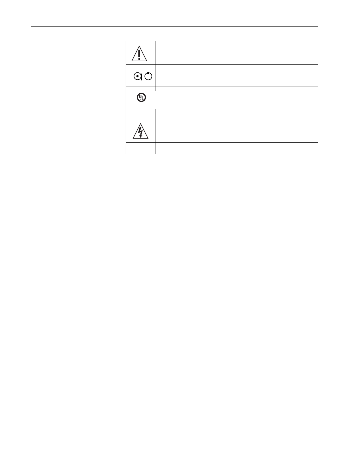
Equipment Symbols
Type BF equipment. The acquisition module is protected from defibrillation
shocks.
Alternating current.
Equipotential.
Charge the battery. The flashing amber LED next to this symbol indicates
you must connect the system to AC power to re-charge the battery.
Do NOT throw the battery into the garbage.
Recycle the battery.
1-16 MAC 5000 System Revision A
2020300-016
Page 29
Introduction: Safety Information
Consult accompanying documents.
This position of the switch removes battery power from the equipment.
I
S
F
S
I
E
A
L
C
R
C
MEDICAL EQUIPMENT
UL 2601-1 CAN/CSA 601.1
4P41
Classified with respect to electric shock, fire, mechanical, and other
D
US
specified hazards only in accordance with UL 2601-1, CAN/CSA C22.2 No.
601-1, CAN/CSA C22.2 No. 601-2-25, EN 60601-2-25, EN 60601-1-1, IEC
60601-1-2: 2001.
To reduce the risk of electric shock, do NOT remove cover (or back). Refer
servicing to qualified personnel.
098A, 096A, 108A, 101A, 102A, 103A, 100A, 181A, 099A
Revision A MAC 5000 System 1-17
2020300-016
Page 30

Service Information
Service Requirements
Refer equipment servicing to GE Medical Systems Information
Technologies authorized service personnel only. Any unauthorized
attempt to repair equipment under warranty voi ds that warranty.
It is the user’s responsibility to report the need for service to GE Medical
Systems Information Technologies or to one of their authorized agents.
Equipment Identification
Every GE Medical Systems Information Technologies device has a
unique serial number for identification. The serial number appears on
the device label
Introduction: Service Information
### ## ## #### # #
ABCDEF
A
B Year Manufactured (00-99)
C Fiscal Week Manufactured
D Production Sequence Number
1
Product Code
00 = 2000
01 = 2001
02 = 2002
(and so on)
1-18 MAC 5000 System Revision A
2020300-016
Page 31

Introduction: Service Information
E Manufacturing Site
F Miscellaneous Characteristic
1. The product code for MAC 5000 systems is AAY.
Revision A MAC 5000 System 1-19
2020300-016
Page 32

Introduction: Service Information
1-20 MAC 5000 System Revision A
2020300-016
Page 33

2 Equipment Overview
Revision A MAC 5000 System 2-1
2020300-016
Page 34

For your notes
2-2 MAC 5000 System Revision A
2020300-016
Page 35

Equipment Overview: Equipment Description
Equipment Descrip ti on
Front View
A
B
C
115A
Name Description
A display screen View the waveform and text data.
B disk drive slot Insert a diskette to store ECG orders or recorded ECG data.
C keyboard Press the keyboard keys to control the system or to enter data.
Revision A MAC 5000 System 2-3
2020300-016
Page 36

Back View
Equipment Overview: Equipment Description
C
D
A
B
117A
Name Description
A back panel connectors Connect peripheral devices here.
B green AC power light Indicates the system is connected to AC power.
C amber battery light Indicates the battery is re-charging.
D internal access button Press to open the system to change paper or the battery.
Internal View
B
A
C
D
E
116A
Name Description
A battery Recharge when the battery icon flashes onscreen.
B writer door Open to replace paper or the battery.
C acquisition module connector Connect the acquisition module cable here.
D paper tray Place paper here.
E STD or A4 Indicates the size of paper (standard or A4) the tray holds.
2-4 MAC 5000 System Revision A
2020300-016
Page 37

Connectors
Back Panel
Equipment Overview: Equipment Description
ABC D E F G H I
118A
:$51,1*
Leakage Current — Keep leakage current within
acceptable limits when connecting auxiliary equipment
to this device.
Total system leakage current must not exceed 100
microamperes.
Name Description
A A Connect an optional card reader or optional bar code reader.
B 1 Connect a GE Medical Systems Information Technologies
KISS pump.
C 2 Connect a local transmission cable, serial line, modem, or
client bridge (wireless option).
D ANA/TTL Connect a device requiring analog data or TTL trigger.
E EXT.VID. Connect an external video display.
F IR Point at a MAC 5000 or MUSE CV system’s IR transceiver to
transmit or receive ECG data.
G card slot Insert the system card into this slot to run the system.
H ground lug Connect non-grounded peripheral devices to ensure
equipotential.
I main AC power Insert the main AC power cable.
Revision A MAC 5000 System 2-5
2020300-016
Page 38

Equipment Overview: Equipment Description
A
B
Back Panel (Exercise Option)
118A
:$51,1*
Leakage Current — Keep leakage current within
acceptable limits when connecting auxiliary equipment
to this device.
Total system leakage current must not exceed 100
microamperes.
Keyboard
Name Description
A 1 Connect a T2000 treadmill or external blood pressure device
cable to this port.
B ANA/TTL Connect an analog treadmill, ergometer cable or TTL trigger to
this port.
127(
Ergoline bicycle ergometers require connections to both ports.
127(
Your keyboard may be slightly different than that shown.
2-6 MAC 5000 System Revision A
2020300-016
Page 39

Equipment Overview: Equipment Description
A
B
C
D
E
F
G
H
N M L K J I
152B
Name Description
A function keys Selects screen menu functions.
B Power Powers the system on or off.
C delete Erases typed characters.
D Copy Prints another ECG report.
E ECG Acquires an ECG. Press to acquire a 12SL resting ECG, including measurements and interpretation.
F Rhythm Prints continuous ECG data. This data cannot be stored or transmitted.
G Stop Stops the writer from printing.
H arrow pad Moves the cursor left, right, up, or down. Press the center to select a highlighted m enu or screen item.
I return Enters information into the system. Throughout the manual, this key is referred to as “the return key.”
J information Provides additional user information.
K space bar Adds a space between typed characters or highlights screen items.
L option Used to create special characters on non-English keyboards.
M esc Returns you to a previous menu.
N shift Creates a capital letter. Press shift + p to type a capital P.
Keyboard–Exercise Test Keys (Option)
Revision A MAC 5000 System 2-7
2020300-016
Page 40

Equipment Overview: Equipment Description
Your keyboard may be slightly different than that shown.
ABCD E F G
HIJKL
152B
Name Description
A Pretest Press to advance to the pretest phase*.
B Exercise Press to advance to the exercise phase*.
C Recovery Press to advance to the recovery phase*.
D Test end Press and hold to end the test and start the test end phase.
E Speed W+/– Press to manually change the belt speed or ergometer load.
F Grade up/down Press to change the elevation of the treadmill belt.
G Start/STOP
Press to start or stop the treadmill during the test.
tmill
H Recall Press to print a 10-second delayed recall report.
I 12 ld Press to print a 12 lead report (10 seconds of acquired data).
J Medians Press to print a medians report.
K Comment Press to enter comments about the test. Comments are
printed on many of the final reports.
L Enter BP Press to enter BP readings or to trigger a reading from an
external device.
*Or advance to next stage within the selected phase.
2-8 MAC 5000 System Revision A
2020300-016
Page 41

Acquisition Module
Equipment Overview: Equipment Description
A
N R C1 C2 C3 A1 A2 A3 A4 C4 C5 C6 L F
E
231
B
C
D
161B
:$51,1*
Burn Protection — To ensure defibrillator protection and
protection against high-frequency burns, use only the
CAM-14 acquisition module with this equipment.
Otherwise, serious injury could result.
&$87,21
Proper Leadwire Connection — Improper connection will
cause inaccuracies in the ECG.
Trace each individual leadwire from its ac quisition
module label to the colored connector and then to the
proper electrode to ensure that it is matched to the
correct label location.
Name Description
A leadwires Attach to the patient’s electrodes. The acquisition module uses either 10 or 14 leadwires.
B rhythm button Press to print a rhythm strip.
C stop writer button Press to stop the writer from printing.
Revision A MAC 5000 System 2-9
2020300-016
Page 42

D acquisition module cable Insert into the system’s internal acquisition module connector.
E ECG button Press to record an ECG.
Leadwire Labels
10 Leadwire AHA
RL RA V1 V2 V3
Equipment Overview: Equipment Description
Name Description
127(
If you enable the Preview before analysis function, press (E) to view
the data. Then, either pres s (E) again to analy ze the data or pres s (C)
to discard the data.
One of the following leadwire labels may appear on the acquisition
module.
14 Leadwi re IEC
V5 V6 LA LL
V4
N R C1 C2 C3
HE
M
C5 C6 L F
C4
I
14 Leadwire AHA
RL RA V1 V2 V3
HE
13 Leadwire AHA Pediatric
V7
RL RA V1 V2 V3
V3R V4R
10 Leadwire IEC
N R C1 C2 C3
Leadwire Adapters
13 Leadwi re IEC Pediatric
V5 V6 LA LL
M
I
V4
N R C1 C2 C3
C3R
C4R
C7
C5 C6 L F
C4
14 Leadwire AHA AUX
V5 V6 LA LL
V4
RL RA V1 V2 V3
A1 A2
A3
A4
V4
V5 V6 LA LL
14 Leadwire IEC AUX
C5 C6 L F
C4
204B
N R C1C2C3
A3A1 A2 A4
C5 C6 L F
C4
205B
The MULTI-LINK leadwires require an adapter to connect to an
electrode.
2-10 MAC 5000 System Revision A
2020300-016
Page 43

Equipment Overview: Equipment Description
4 mm pin
Grabber
MACTRODE clip
Leadwire end
119B
Revision A MAC 5000 System 2-11
2020300-016
Page 44

Equipment Overview: Getting Started
Getting Started
Prepare the Equipment for Use
Modem Option
See the MAC 5000 Field Servi ce Ma nual for in formatio n about mount ing
and connecting the modem option.
MobileLink Wireless Option
See the MobileLink Installation and Troubleshooting Guide for
information about mounting, configuring, and connecting the wireless
option.
Connect External Devices (Exercise Option)
Your MAC 5000 system can connect at port 1 with the following devices:
GE Medical Systems Information Technologies Series T2000
treadmills,
SunTech Tango blood pressure device,
Colin STBP-780 blood pressure device, or
Ergoline 900/900L integrated blood pressure device.
127(
Before using external devices the MAC 5000 must be properly set up
(see Chapter 14, “System Setup” ) and exercise protocols must be
properly defined (see Chapter 7, “Editing Protocols” ).
Your MAC 5000 system can connect at the ANA/TTL port with the
following devices:
The Ergoline 800 ergometer.
The Ergoline 900 ergometer.
The Lode ergometer.
2-12 MAC 5000 System Revision A
2020300-016
Page 45

Equipment Overview: Getting Started
127(
Other bicycle ergometers and treadmill models with an analog
port can be connected to the analog output of the MAC 5000.
A TTL QRS trigger signal for external devices can be connected to
the ANA/TTL port.
Connect the Acquisition Module Cables
Insert Disk into Disk Drive
Verify Correct Operation
156A
Plug the cables into the front of the acquisition module. Refer to
“Acquisition Module” on page 2-9 for more information.
Insert a disk with enough available capacity into the disk drive before
using the device. Use a computer to check the content s/available capacity
of a disk.
Press power to turn on the MAC 5000 System.
If the system starts up wit hout displaying error messages, the
system is operational.
If the system displays error messages, turn the system power off,
then on again. If error messages persist, contact GE Medical Systems
Information Technologies Service.
Revision A MAC 5000 System 2-13
2020300-016
Page 46

Software Description
Start Up Screen
Equipment Overview: Getting Started
B C D E
A
Press ECG to record an ECG
MAC5000 XXXX
I
II
III
aVR
aVL
aVF
***
BPM
V1
V2
V3
F
V4
V5
V6
157A
Name Description
A software version Displays the system’s software version during the first few seconds of power up.
B user prompts Provides additional information.
C Hookup Advisor Displays quality of patient hookup. This can be turned on or off.
D function icon Indicates the Main Menu function the system is using. This is the Resting ECG function.
E battery status icon Indicates how much charge the battery has available.
F menu Provides access to additional settings or functions.
Main Menu
Use the Main Menu to select the different functions available on this
system. The functions di sp laye d in yo ur Main Menu may vary due to the
installation of purchased software options.
2-14 MAC 5000 System Revision A
2020300-016
Page 47

Equipment Overview: Getting Started
Start Up Screen (Exercise Option)
AB C D E F G H I J K L
EXERCISE
0:20
STAGE 1
0:20
Waiting for Stable Heart Rate
V1
II
V5
Name Description
A system messages Error or informational messages appear in this area.
BRUCE
10 Watts
Patient Data
75
120/80
MD1207-028D
155
BP
B current heart rate bar
graph
C workload level Indicates the units of measurement and can be changed.
D phase and stage
clocks
E current phase and
stage name
F protocol name The name of the selected protocol is displayed.
G Rhythm formats Use System Setup (see Chapter 14, “System Setup” ) or Ld Select to change the leads
H medians Current, pretest.
I systolic/diastolic
blood pressures
J current heart rate Determined by the three leads displayed on your screen during the PRE-TEST phase.
The top horizontal line is the maximum predicted heart rate (220 - age) . The line below that is the
target heart rate (a percentage of 220 - age). At the start of EXERCISE phase, a third line
representing the resting heart rate will appear.
The top clock displays the total time in a phase. The bottom clock displays the time in a stage.
During the TEST-END phase, the top clock displays total time in the EXERCISE phase and the
bottom clock displays total time in the RECOVERY phase.
Top is phase name, bottom is stage name.
displayed and printed.
The BP numbers become dim if the BP has not changed in over one minute.
Revision A MAC 5000 System 2-15
2020300-016
Page 48

K function icon Indicates the Main Menu function the system is using. This is the Exercise function.
L battery status icon Indicates how much charge the battery has available.
Main Menu
Equipment Overview: Getting Started
Name Description
Use the Main Menu to select the different functions available on this
system. The functions di sp laye d in yo ur Main Menu may vary due to the
installation of purchased software options.
1. Select More from the start up scre en.
2. Select Main Menu to begin di splaying the Main Menu functions.
Main
Resting ECG PediatricECG Vector Loops 15 Lead ECG
+
Exercise12
File Manager SystemSetup
Exercise15
?
Master’s Step
Receive
Hi-Res
MUSE
?
RemoteQuery Ord Mgr Int.
Return
EditProtocol
PHi-Res
A
More
More
More
More
182A
2-16 MAC 5000 System Revision A
2020300-016
Page 49

Main Menu Functions
Function Description
076A
Resting ECG
077A
Pediatric ECG
078A
Vector Loops
085A
15 lead ECG
Equipment Overview: Getting Started
Records a 12-lead ECG.
Records a 15-lead pediatric ECG. The standard 12 leads and the V3R, V4R, and V7 leads are
used.
Records a 15 lead vector cardiogram. The standard 12 leads and the X,Y,Z leads are used.
Records an adult 15 lead ECG. The standard 12 leads and three user-defined leads are used.
EditProtocol
251A
Exercise12
252A
Exercise15
253A
Master’s Step
+
079A
Hi-Res
084A
PHi-Res
EditProtocol creates new or edits existing exercise test protocols. Also, a protocol can be saved,
printed, or erased.
250A
Exercise12 conducts the 12-lead exercise test and allows you to print reports. This is a
purchased option.
Exercise15 conducts the 15-lead (12 standard, 3 user defined leads) exercise test and allows
you to print reports. This is a purchased option.
Runs the Master’s Step exercise protocol. (Japan only.)
Records a signal-averaged high-resolution ECG. This is a purchased option.
Records a p-wave signal-averaged high-resolution ECG. This is a purchased option.
Revision A MAC 5000 System 2-17
2020300-016
Page 50

Equipment Overview: Getting Started
Function Description
Prints, edits, displays, transmits, and deletes ECG data stored to a disk.
080A
File Manager
?
082A
Defines the operating parameters of the system.
System Setup
Receives ECG data from other devices.
081A
Receive
Requests, displays, and prints confirmed ECGs retrieved from a MUSE CV system. This is a
purchased option.
083A
MUSE
?
Remote Query
Acquires, prints, and stores ECG orders received from a MUSE CV system with a Hospital
086A
A
Information System (HIS) interface.
Ord Mgr Int.
Return to the previous screen.
271A
Return
Selecting Menu Functions
The following shows two methods for selecting a menu function.
Pressing a Function Key
To select More, press the function key directly below More.
2-18 MAC 5000 System Revision A
2020300-016
Page 51

Using the Arrow Pad
Equipment Overview: Getting Started
More
162A
To select More:
1. Press the right arrow on the arrow pad until More is high l i gh t ed .
1.
More
176A
2. Press the middle of the pad to select More.
To select a menu function:
1. Use the arrow keys to highlight the desired item.
2. Press the middle of the pad to select the highligted item.
3. Select the appropriate function.
Revision A MAC 5000 System 2-19
2020300-016
Page 52

Equipment Overview: Getting Started
Entering Data
Type Data into a Highlighted Field
1. Press the right or down arrow to highlight the First name field.
1.
Last name
First name
Selecting Items from a List
163A
2. Type the patient’s first name.
3. Press the middle of the pad or the return key to enter the
information. The cursor goes to the next data field.
1. Press the right arrow to highlight Gender.
2. Press the middle of the pad to lock the list in place.
2-20 MAC 5000 System Revision A
2020300-016
Page 53

Equipment Overview: Getting Started
3.
Male
Female
167A
4. Press the down arrow to highlight Male or Female.
5. Press the middle of the arrow pad to confirm the selection. The
cursor goes to the next data field.
Revision A MAC 5000 System 2-21
2020300-016
Page 54

Equipment Overview: Getting Started
2-22 MAC 5000 System Revision A
2020300-016
Page 55

3 Preparing the Patient
Revision A MAC 5000 System 3-1
2020300-016
Page 56

For your notes
3-2 MAC 5000 System Revision A
2020300-016
Page 57

Preparing the Patient: Prepare the Patient’s Skin
Prepare the Patient’s Skin
127(
To use the KISS Electrode Application System, see the KISS
operator’s manual for instructio ns. (The KISS s ystem is not available
for sale in the United States.)
Careful skin preparation is the key to an interference-free ECG. The
signal quality is shown on the Hookup Advisor indicator.
1. Shave any hair from each electrode site and degrease each electrode
site with alcohol. If c onducti ng a st ress te st, proc eed to st eps 2 and 3 .
If you are not conducting a stress test, skip ahead to step 4.
2. Mark each electrode site with a felt tip pen.
3. Remove the epidermal skin layer at each electrode site (i.e. remove
the mark left from the felt tip pen) . Use a n abra sive pad or sk in prep
cream.
4. Apply electrode to prepared area.
5. Look at the lead-check screen for indication of lead problems.
127(
Use only electrodes and contact agents recommended by GE
39A
Revision A MAC 5000 System 3-3
2020300-016
Page 58

Preparing the Patient: Prepare the Patient’s Skin
Medical Systems Info rmation Technologies. The sig nal quali ty on
the lead-check screen will not be indicated until the RA/R
electrode has been applied. When RA/R becomes disconnected,
the system will report that all electrodes are off the patient.
:$51,1*
Shock Hazard — Ensure that conductive parts of the
electrodes or lead wires do not come in contact with other
conductive parts.
This would cancel the p rot ectio n prov id ed by the i so lat ed
signal input.
:$51,1*
Conductive Parts — Keep the conductive parts of lead
electrodes and associated parts away from other
conductive parts, including earth.
3-4 MAC 5000 System Revision A
2020300-016
Page 59

Preparing the Patient: Apply the Electrodes
01B
Apply the Electrodes
Resting Electrodes
Standard 12 Lead Placement
&$87,21
Proper Leadwire Conenection — Improper connection will
cause inaccuracies in the ECG.
Trace each individual leadwire from its ac quisition
module label to the colored connector and then to the
proper electrode to ensure that it is matched to the
correct label location.
AHA
Label
IEC Label Electrode Placement
A V1 red C1 red Fourth intercostal space at the right sternal border.
B V2 yellow C2 yellow Fourth intercostal space at the left sternal border.
C V3 green C3 green Midway between location B and D.
J
A
B
C
D
I
G
D V4 blue C4 brown Mid-clavicular line in the fifth intercostal space.
E
F
H
E V5 orange C5 black Anterior axillary line on the same horizontal level as D.
F V6 purple C6 purple Mid-axillary line on the same horizontal level as D and E.
G LA black L yellow Left deltoid.
H LL red F green Above left ankle. (Alternate placement, upper leg as close to torso
as possible.)
I RL green N black Above right ankle. (Alternate placement, upper leg as close to
torso as possible.)
J RA white R red Right deltoid.
Revision A MAC 5000 System 3-5
2020300-016
Page 60

Preparing the Patient: Apply the Electrodes
Standard 15 Lead Placement
A V1 red C1 red Fourth intercostal space at the right sternal
B V2 yellow C2 yellow Fourth intercostal space at the left sternal
J
A
B
K
C
D
G
C V3 green C3 green Midway between location B and D.
E
F
D V4 blue C4 brown Mid-clavicular line in the fifth intercostal space.
AHA Label IEC Label Electrode Placement
border.
border.
I
H
E V5 orange C5 black Anterior axillary line on the same horizontal
088A
level as D.
F V6 purple C6 purple Mid-axillary line on the same horizontal level as
D and E.
G LA black L yellow Left deltoid.
H LL red F green Above left ankle. (Alternate placement, upper
L
M
leg as close to torso as possible.)
I RL green N black Above right ankle. (Alternate placement, upper
089A
leg as close to torso as possible.)
J RA white R red Right deltoid.
K V4R gray C4R gray Right anterior chest opposite of D.
L V8 gray C8 gray Under left midscapular line.
M V9 gray C9 gray Left paraspinal border.
3-6 MAC 5000 System Revision A
2020300-016
Page 61

Frank X,Y,Z Placement
H
A
Preparing the Patient: Apply the Electrodes
AHA Label IEC Label Electrode Placement
A LA black L yellow Just below the clavicle of the left arm.
B E orange E light blue Mid-sternum on the same horizontal level as C
and D.
C V4 blue C4 brown Mid-clavicular line in the fifth intercostal space.
B
G
F
C
I
J
NEHB Placement
D
D V6 purple C6 purple Mid-axillary line on the same horizontal level as
C.
E LL red F green Left leg, lower abdominal quadrant.
02B
E
F RL green N black Right leg, lower abdominal quadrant.
G I orange I light blue Right mid-axillary line on the same horizontal
level as C and D.
H RA white R red Just below the clavicle of the right arm.
I H orange H light blue Back of neck, avoid the caroti d artery and
jugular vein.
J M orange M light blue Center of spine on the same horizontal level as
03B
C and D.
To acquire a NEHB ECG , use t he S tanda rd 1 2 Lea d ele ctro de pl a cemen t
and items A and B shown below.
Revision A MAC 5000 System 3-7
2020300-016
Page 62

Preparing the Patient: Apply the Electrodes
AHA Label IEC Label Electrode Placement
A A1 orange Nst white A ttachment point of the 2nd rib to the right
sternal edge.
B A2 orange Nax white 5th intercostal space on the left posterior
axillary line. (Same position as V8 or C8.)
A
C V4 blue Nap white Mid-clavicular line in the fifth intercostal space.
B
C
33A
(Same position as C4.)
3-8 MAC 5000 System Revision A
2020300-016
Page 63

Pediatric Placement
J
A
B
C
L
K
F
E
D
Preparing the Patient: Apply the Electrodes
AHA Label IEC Label Electrode Placement
A V1 red C1 red Fourth intercostal space at the right sternal
border.
B V2 yellow C2 yellow Fourth intercostal space at the left sternal
border.
G
C V3 green C3 green Midway between location B and D.
D V4 blue C4 brown Mid-clavicular line in the fifth intercostal space.
I
H
E V5 orange C5 black Anterior axillary line on the same horizontal
04B
F V6 purple C6 purple Mid-axillary line on the same horizontal level as
G LA black L yellow Left deltoid.
H LL red F green Above left ankle. (Alternate placement, upper
M
I RL green N black Above right ankle. (Alternate placement, upper
05B
J RA white R red Right deltoid.
K V4R gray C4R gray Mid-clavicular line in the fifth right intercostal
L V3R gray C3R gray Halfway between A and K.
M V7 gray C7 gray Same horizontal level of D in the left posterior
Exercise Electrodes (with Exercise–Option)
level as D.
D and E.
leg as close to torso as possible.)
leg as close to torso as possible.)
space.
axillary line.
In addition to the standard electrodes, apply one electrod e on the
sternum (A1) and one in location V5R/C5R (A2). It is recommended that
arm electrodes be placed on the patient’s torso, just under the clavicles.
Revision A MAC 5000 System 3-9
2020300-016
Page 64

Preparing the Patient: Apply the Electrodes
CM5, CC5, ML Lead Placement
Electrode Electrode Placement
A1 Mid-sternum at the second intercostal space.
A2 In the fifth intercostal space in the right anterior axillary line (V5R/C5R).
254A
In addition to the standard electrodes, apply one electrod e on the
sternum (A1), one in location V5R/C5R (A2), and one on the neck (A3).
CM5, CC5, CH Lead Placement
Electrode Electrode Placement
A1 Mid-sternum at the second intercostal space.
A2 In the fifth intercostal space in the right anterior axillary line (V5R/C5R).
A3 On either side of the neck or anywhere above the shoulders.
255A
3-10 MAC 5000 System Revision A
2020300-016
Page 65

4 Entering Patient
Information
Revision A MAC 5000 System 4-1
2020300-016
Page 66

For your notes
4-2 MAC 5000 System Revision A
2020300-016
Page 67

Entering Patient Information: Enter Patient Information
Enter Patient Information
127(
Before entering patient data, be sure that the unit is powered on and
that a diskette is in the disk drive.
Enter the Information
Select F1 (Patient Data) for each new patient.
&$87,21
Accurate Patient Data — Patient data may be retained
from a previous patient. Be sure to check the patient info
screen for each new patient. Data assigned to the wrong
patient causes erroneous patient data that can affect
diagnosis and treatment of the patient(s).
Make sure that you enter patient data for the correct
patient.
127(
Our equipment contains several fields which can be filled in before
performing an ECG. Some of these fields must be filled in before
performing an exam, some are optional and ther efor e left to the user
to assess whether they are needed to perform the exam. A field
RACE is one of these optiona l fields. It has be en acknowl edged by the
medical profession as useful to anal yze so me pathol ogies. You sh ould
be aware that, in some jurisdictions, the processing of data revealing
an individual’s racial origin is subject to legal requirements, such as
obtaining the patient's prior consent. If you elect to collect this type
of data, it is your responsibility to ensure that you comply with all
applicable legal requirements.
Revision A MAC 5000 System 4-3
2020300-016
Page 68

Entering Patient Information: Using a Patient Card Reader (Option)
Using a Patient Card Reader (Option)
Connect and Configure the Card Reader
1. Connect the card reader to the A port on the back panel of the MAC
5000.
2. Configure the card reader. See “Card Reader Option Setup ” on
page 14-31.
Slide Card
Slide the patient data card through the optional card reader when you
are prompted.
4-4 MAC 5000 System Revision A
2020300-016
Page 69

Entering Patient Information: Using a Bar Code Reader (Option)
Using a Bar Code Reader (Option)
Connect and Configure the Bar Code Reader
1. Connect the bar code reader to the A port on the back panel of the
MAC 5000.
2. Configure the bar code reader. See Chapter “Bar Code Reader Option
Setup” on page 14-33.
Scan the Bar Code
Scan the patient’s bar code with the bar code reader when you a re
prompted.
127(
Do not use the bar code reader f or scanning the bar code t hat appears
on the ECG printout. The bar code on ECG printout is of a different
format and not readable by the bar code reader.
Revision A MAC 5000 System 4-5
2020300-016
Page 70

Entering Patient Information: Receive Orders from a MUSE CV System (Option)
Receive Orders from a MU SE C V Syst em (O p tion )
Preparation
The MUSE CV System can communicate orders to a MAC 5000 System
in the following ways:
via modem,
Line
MAC 5000
via infrared, and
MAC 5000
via wireless communication (MobileLink or MobileLink UHS
Modem
264A
1-3ft
30.4-91.4cm
MUSE CV
infrared de vice
265A
wireless system). Instructions for mounting, configuration, and
connecting the client bridge to the MAC 5000 can be found in the
MobileLink or MobileLink UHS Installation and Troubleshooting
Guide.
127(
Performance of the MobileLink wireless system may vary due to
changes in RF (radio frequency) properties of your site or
environmental conditions. If you are experiencing intermittent
connectivity in certain areas of your facility, re-i nitiat e the proce ss of
receiving from the MUSE system. Consult your hospital IT
department or your local GE Medical Systems Information
4-6 MAC 5000 System Revision A
2020300-016
Page 71

Entering Patient Information: Receive Orders from a MUSE CV System (Option)
Technologies networking professional regarding modificatio n of your
wireless LAN to improve system performance.
Load the Orders
127(
Before receiving orders from the MUSE CV system, be sure that the
unit is powered on and that a diskette is in the disk drive.
1. Select Ord Mgr Int. The Order Manager interface opens.
2. Select Load Orders.
3. Choose to delete the old orders or load the new orders.
4. Enter the location(s) from which the device should retrieve the
orders.
Select the Orders to Receive
1. Select one or more orders.
2. Select Return. The system stores the orders.
Select an Order to Complete
1. Select Select.
2. Select an order.
3. Select Continue to proceed with selecting this order. The system will
then go to the ECG test.
or
Select Cancel to abort the selection of this order. You can then select
a different order to complete.
Complete the Order
1. Select Patient Data. The patient data window for this patient
displays.
2. Enter patient data or modify the patient data that is diaplayed.
3. Select Return to proceed with completing this order. The system will
then go to the ECG test.
Revision A MAC 5000 System 4-7
2020300-016
Page 72

Entering Patient Information: Enter Orders Manually (Option)
Enter Orders Manually (Option)
127(
Before manually creating orders, be sure that the unit is powered on
and that a diskette is in the disk drive.
Manually Create an Order
1. Select Ord Mgr Int. The Order Manager interface opens.
2. Select Create Order. A window opens to enter the manual order.
3. Enter the patient data.
4. Select Return to close the window. The system saves the order.
Selecting and Completing Manually Created Orders
Manually created orders are selected and completed the same way
downloaded orders are selected and completed.
Refer to “Select an Order to Comp lete” on page4-7 for information on
selecting an order.
Refer to “Complete the Order” on page 4-7 for information on
completing an order.
4-8 MAC 5000 System Revision A
2020300-016
Page 73

5 Recording an ECG
Revision A MAC 5000 System 5-1
2020300-016
Page 74

For your notes
5-2 MAC 5000 System Revision A
2020300-016
Page 75

Hookup Advisor
Recording an ECG: Hookup Advisor
The MAC 5000 System offers the Hookup Advisor feature, which is a tool
for monitoring the quality of resting ECG signals, and is available in the
resting, pediatric, 15 lead, vector loops, and Master’s Step applications.
It can reduce or eliminate the occurrenc e of poor techni cal qua li ty ECGs,
save time, and prevent the need for retakes.
When Hookup Advisor is enabl ed, a t hree -circl e indi cator a ppe ars on t he
display.
Red indicates a lead-fail condition or extreme baseline shifts. The red
indicator is always the leftmost circle of the of the indicator.
Yellow indicates muscle artifact, power line interference, baseline
wander, or electrode noise. The yellow indicat or is al ways the middl e
circle of the of the indicator.
Green indicates generally acceptable signal quality. The green
indicator is always the rightmost circle of the of the indicator.
Hookup Advisor indicator
Press ECG to record an ECG
***
BPM
I
II
III
aVR
aVL
aVF
V1
V2
V3
V4
V5
V6
157A
When the lead quality is Red or Yellow, a message describing the lead
problem or status is disp layed on the screen.
Revision A MAC 5000 System 5-3
2020300-016
Page 76

Recording an ECG: Hookup Advisor
Hookup Advisor is enabled and configured in the ECG Acquisition menu
(System Setup > ECG > ECG Acquisition). Refer to “ECG Acquisition” on
page 14-15 for more information. In addition to enabling/disabling the
Hookup Advisor feature, you can set the level at which the MAC 5000
System acknowledges poor signal quality. The acknowledgement level
can be set to Yellow (default), Red, or Never.
Hookup Advisor continuously reviews the ECG data for acceptable lead
quality.
If Pre-acquisition is enabled in the system setup, the lead quality
(circle) indicator will reflect the entire previous 10 seconds of ECG
data. Any displayed messages will be updated on a real-time basis to
reflect adjustments/improvements to the lead quality. Once any lead
quality problems have been remedied, the message Please wait... will
be displayed until the entire 1 0 second period is free from lead
quality problems.
When Pre-acquisition is not enabled, the Hookup Advisor level and
messages will respond to a fixed poor lead quality problem within 2 –
3 seconds.
When an ECG is a cqu ired , Hook up Advi sor will ru n a c omple te and m ore
comprehensive assessment of the full 10 seconds of ECG data and
possibly prompt the user regarding any poor lead quality conditions.
If Preview before analysis is turned off in the system setup, a lead
quality message and prompt may be displayed, depending on the
current lead quality level and the Prompt level in the syste m setu p.
If a message and prompt is displayed, the lead quality indicator will
reflect the overall 10-second lead quality.
If Preview before analysis is enabled, the system setup Prompt level
is disregarded and the system immediately displays the Preview
screen. Any lead quality messages will be displayed in this screen
along with the overall 10-second lead quality indicator.
In either case, users may then either:
Select Continue to continue (print the ECG), or
Select Cancel to cancel.
5-4 MAC 5000 System Revision A
2020300-016
Page 77

Recording an ECG: Record a Resting, Pediatric, Vector Loops, or 15 Lead ECG
Record a Resting, Pediatric, Vector Loops, or 15 Lead ECG
127(
Before recording an ECG, be sure that the unit is powered on and
that a diskette is in the disk drive.
127(
See “Enable or Disable the ACI-TIPI Option” on page 14-5 to enable
or disable ACI-TIPI.
Record the ECG
Press the ECG button to initiate the recording of the ECG.
Print Another Report
Store the ECG
Transmit the ECG
Press the copy button to initiate another printout of the ECG report.
If the Saving file to Disk message app ea rs, the E CG is be ing sav ed to the
diskette.
If the Saving file to Disk message did not appear, sele ct Store to save the
ECG to diskette.
If the Establishing network connection message appeared, the ECG is
preparing to transmit.
If the Establishing network connection message did not appear, you will
need to manually initiate the transmission. Refer to Chapter 9,
“Transmitting an ECG” for more information.
Revision A MAC 5000 System 5-5
2020300-016
Page 78

Recording an ECG: Record a Signal Averaged ECG (Options)
Record a Signal Averaged ECG (Options)
127(
Before recording a signal averaged ECG, be sure that the unit is
powered on and that a diskette is in the disk drive.
1. Select Hi-Res or PHi-Res to enable the system to record a signal
averaged ECG.
127(
To record a PHi-Res ECG, GE Medical Systems Information
Technologies recommends a target noise level of 0.3MV or less.
2. Select Template to initiate the signal averaged ECG recording.
3. Change the seed beat:
a. Select Display.
b. Select SelectQRS.
c. Select a new seed beat.
4. Select Average to average the ECG data.
5. Select Store to store the ECG data.
6. Select Transmit to transmit the ECG data. Refer to Chapter 9,
“Transmitting an ECG” for more information.
5-6 MAC 5000 System Revision A
2020300-016
Page 79

Recording an ECG: Record a Master’s Step Test (Option)
Record a Master’s Step Test (Option)
127(
Before recording a Master’s Step test, be sure that the unit is
powered on and that a diskette is in the disk drive.
1. Select Master’s Step.
2. Enter the patient’s demographics either manually with the keyboard
or by using the card reader/bar code reader.
3. In the Setup menu, confirm that the following parameters are
correct:
Number of Steps,
Test Type,
Post J (ms),
Step Counter Display,
Run the Test
Sound Option
Continuous Recording, and
Post Exercise ECG Time.
Press the return key.
4. Press the ECG button to record a pre-exercise ECG.
1. Remove the leadwires from the patient (to prevent the patient from
tripping on the leadwires ) . Keep the electrodes on the patie nt.
2. Press Continue to begin the exercise t est.
3. When the patient finishes the exerci se, immediately reattach the
leadwires to the electrodes. Check the waveform quality on the
screen to confirm that all leadwires are correctly reattached.
4. The MAC 5000 automatically records additional ECGs requested.
5. Once you record all ECGs, a final report prints.
6. Select Store to store the ECG data.
Revision A MAC 5000 System 5-7
2020300-016
Page 80

Recording an ECG: Record a Master’s Step Test (Option)
7. Select Transmit to transmit the ECG data. Refer to Chapter 9,
“Transmitting an ECG” for more information.
5-8 MAC 5000 System Revision A
2020300-016
Page 81

Recording an ECG: Using ACI-TIPI (Option)
Using ACI-TIPI (Option)
127(
Before using the A CI-TIPI opt ion, be sur e that th e unit is po wered on
and that a diskette is in the disk drive.
Refer to Chapter 14, “System Setup” for information on enabling the
ACI-TIPI option.
You must have a report “with interpretation” selected in System setup in
order to obtain an ACI-TIPI report.
1. Enter the patient’s demographics either manually with the keyboard
or by using the card reader/bar code reader.
2. Press the ECG button.
3. Enter the ACI-TIPI data.
Age (18-40, 41-50, >50),
Gender (Male/Female), and
Chest or Left Arm Pain (Chief Complaint, Secondary Complaint,
Not Present).
Chief Complaint: Select this option if the complaint of chest
or left arm pain is the primary reason the patient came to the
hospital.
Secondary Complaint: Select this option if the complaint of
chest or left arm pain is secondary– the patient came to the
hospital because of other symptoms.
Not Present: Select this option if the patient has no chest or
left arm pain or equivalent discomfort.
Select Return.
4. Print, store, and transmit the ECG based on instructions given on
page 5-5.
Revision A MAC 5000 System 5-9
2020300-016
Page 82

Recording an ECG: Using ACI-TIPI (Option)
5-10 MAC 5000 System Revision A
2020300-016
Page 83

6 Exercise Stress Test
(Option)
Revision A MAC 5000 System 6-1
2020300-016
Page 84

For your notes
6-2 MAC 5000 System Revision A
2020300-016
Page 85

Exercise Stress Test (Option): Start an Exercise Stress Test
Start an Exercise Stress Test
127(
Before recording an ECG, be sure that the unit is powered on and
that a diskette is in the disk drive.
You may store data during an exercise test to diskette (see “Final Report”
on page 14-26). The data is stored to the protocol diskette. Make sure
there is sufficient free space on the diskette before starting the test.
Preparation
1. Select Exercise12 or Exercise15 to enter stress test mode.
2. Select Patient Data. The Patient Data Entry screen opens.
3. Enter patient data.
4. Prepare the patient for the test, and attach leadwires. Refer to
Chapter 3, “Preparing the Patient” for more information.
Legal Notice
Exercise Test Keys
5. Select Protocol to open the list of available stress test protocols.
6. Select the desired protocol.
Our equipment contains several fields which can be filled in before
performing an ECG. Some of these fields must be filled in before
performing an exam, some are optional and therefore left to the user to
assess whether they are needed to perform the exam. A field RACE is one
of these optional fields. It has been acknowledged by the medical
profession as useful to analyze some pathologies. You should be aware
that, in some jurisdictions, the processing of data revealin g an
individual's racial origin is subject to legal requirements, such as
obtaining the patient’s prior consent. If you elect to collect this type of
data, it is your responsibility to ensure that you comply with all
applicable legal requirements.
The Exercise test keys perform the functions listed in the table.
Revision A MAC 5000 System 6-3
2020300-016
Page 86

Exercise Stress Test (Option): Start an Exercise Stress Test
Key Function
Pretest Press to advance to the pretest phase.
Exercise Press to advanc e to the exercise phase.
Recovery Press to advanc e to the recovery phase.
Test end Press and hold to end the test and start the test end phase.
Speed W +
Press to increase or decrease the belt speed or ergometer load.
Speed W –
Grade Press to change the elevation of the treadmill belt.
Start tmill Press to start the treadmill during the test.
STOP tmill Press stop the treadmill during the test.
Recall Press to print a 10-second delayed recall report.
12 ld Press to print a 12 lead report.
Medians Press to print a medians report.
Comment Press to enter comments that will be stored with the record and printed
on some of the final reports.
Enter BP Press to enter BP readings or to trigger a reading from an external
device.
6-4 MAC 5000 System Revision A
2020300-016
Page 87

Test Phases
Pretest Phase
Overview
Exercise Stress Test (Option): Test Phases
The pretest phase consists of stages configured in each protocol.
Commonly used stages are:
Supine
Standing
Hyperventilating
You can configure the Protocol Editor to take blood-pressure
measurements manually or automatically. (See Chapter 7, “Editing
Protocols” ).
Operating Steps
The system will beep and display a message prompt in the header of the
display when it is ti me to take a manual blood pressure measurement.
A set of medians is saved at the end of the Pretest phase as baseline
medians.
1. On the stress keypad, press 12 ld to acquire and print a baseline
ECG.
2. Press Pretest to advance to the next PRE-TEST stage.
3. If you are using a treadmill to conduct the exercise test, tell the
patient to place his/her feet on the treadmill frame, not on the belt.
:$51,1*
Fall Hazard — Severe injury can result from a fall.
Patients should wait until the treadmill belt is moving
before stepping onto t he belt. Step onto the belt with one
foot at a time. Avoid rapid changes in belt speed.
Revision A MAC 5000 System 6-5
2020300-016
Page 88

Exercise Stress Test (Option): Test Phases
:$51,1*
Pinch Point Hazard — Hair, jewelry, and loose clothing
can catch in moving parts.
Keep these and other items away from moving parts.
Otherwise, serious injury could result.
Press Start tmill (on the treadmill controller keyboard) to start the
treadmill belt moving. During the exercise test, you can:
Press STOP tmill once (on the treadmill controller keyboard) to
stop the treadmill GRA DUAL L Y.
Press and hold STOP tmill (on the treadmill controller
keyboard) to stop the treadmill belt QUICKLY.
Press the emergency stop button (usually mounted on the
treadmill) to stop the treadmill QUICKLY.
Press Speed W + or Sp eed W – and Grade keys (on the
treadmill controller keyboard) to manually control the test.
However, once you press these keys, you control the speed and
grade during the remainder of the EXERCISE and RECOVERY
phases, not the protocol.
Pretest Phase Buttons
Menu Function
Patient Data Enter a patient’s name, ID number, etc. Enter the patient’s age to allow your system to
New Protocol Select a different exercise test protocol.
Measurements Will allow the system to reestablish the median complex, set the J point, then select the
Leads Select the leads used for 3 or 6 Rhythm leads, All Leads, Lead Check, or Lead
calculate the maximum and target heart rates.
This function is only available if the test will be printed only (not stored to a diskette).
three leads used to calculate heart rate.
Placement.
6-6 MAC 5000 System Revision A
2020300-016
Page 89

Median Select a lead to act as the median lead. This can be a fixed lead or scanned for lead with
Writer Change the writer’s arrhythmia documentation (doc.), cubic spline (baseline control),
Exercise Phase
Overview
Exercise Stress Test (Option): Test Phases
Menu Function
most ST depression.
paper speed, gain, filter, and writer on/off settings.
The selected protocol controls the treadmill or ergometer. When you
enter the exerc ise ph as e:
The belt speed and grade or the ergometer workload change
according to the selected protocol,
The exercise clock (top) starts, and
The system starts to save the test data.
Operating Steps
:$51,1*
Fall Hazard — Severe injury can result from a fall.
Patients should wait until the treadmill belt is moving
before stepping onto t he belt. Step onto the belt with one
foot at a time. Avoid rapid changes in belt speed.
1. Press the Exercise button to begin the exercise phase.
During the test you can manually perform operations from the
function keyboard.
2. Press the Start tmill button if treadmill or ergometer has no t been
started yet.
If you are using an ergometer, the ergometer workload is
automatically controlled.
The exercise test advances automatically through the exercise st ages
unless the operator manually overrides the test.
Revision A MAC 5000 System 6-7
2020300-016
Page 90

Exercise Phase Buttons
Exercise Stress Test (Option): Test Phases
127(
When the stages in the treadmill protocol have durations other
than infinite, the exe rcise test advances from stage to stage
automatically. However, you can press Exercise (on th e
treadmill controller keyboard) at any time t o manually advance
to the next EXER CISE stage.
3. You can manually change a treadmill’s speed and grade however this
puts you in the manual mode for the remainder of the test.
Press Speed W + (to increase speed) within 5 seconds of your
last workload change.
Press Speed W – (to decrease speed) within 5 seconds of your
last workload change.
Press Grade + (to increase grade) within 5 seconds of your last
workload change.
Press Grade – (to decrease grade) within 5 seconds of your last
workload change.
Menu Function
Event Press to display a list of predefined events.
Stage Hold In exercise phase, press to hold current stage.
Measurements Will allow the system to reestablish the median complex, set the J point, then select the
three leads used to calculate heart rate.
Leads Select the leads used for 3 or 6 Rhythm leads, All Leads, Lead Check, or Lead Placement.
Median Select a lead to act as the median lead. This can be a fixed lead or scanned for lead with
most ST depression.
Writer Change the writer’s arrhythmia documentation (doc.), cubic spline (baseline control), paper
speed, gain, filter, and writer on/off settings.
6-8 MAC 5000 System Revision A
2020300-016
Page 91

Recovery Phase
Overview
Operating Steps
Recovery Phase Buttons
Menu Function
Exercise Stress Test (Option): Test Phases
In recovery, the treadmill speed and grade or the ergometer load changes
based on the protocol configuration.
Press the Recovery button to advance to the recovery phase.
The clock begins timing the recovery phase.
A maximum 12-lead measurement is taken (if that is part of the
selected protocol).
Event Press to display a list of predefined events.
Edit Press during Recovery or Test end will allow user to enter or edit patient data, reason for
Measurements Will allow the system to reestablish the median complex, set the J point, then select the
Leads Select the leads used for Rhythm Lead 1, 2, and 3, All Leads, Lead Check, or Lead
Median Select a lead to act as the median lead. This can be a fixed lead scanned for lead with most
Writer Change the writer’s arrhythmia documentation (doc.), cubic spline (baseline control), paper
Test End Phase
Overview
test termination, or comments.
three leads used to calculate heart rate.
Placement.
ST depression.
speed, gain, filter, and writer on/off settings.
After you press and hold Test end button, the foll owing happens:
The system no longer acquires and stores ECG measurement data,
Revision A MAC 5000 System 6-9
2020300-016
Page 92

Operating Steps
Exercise Stress Test (Option): Test Phases
The treadmill and clocks stop, and
Workload/speed/grade no longer display.
127(
The button for Test end MUST be held for more than one s econd
to activate. This is done to prevent the tes t from being stopped by
an accidental key press.
1. Press and hold the Test end button to end the test and st art th e tes t
end phase.
2. Select Reason for termination or Comments to enter information
about this exercise test.
3. Select Continue to return to the TEST-END menu.
A final report prints automatically if you selected this option in the
Edit Protocol function (Select Main Menu
END phase screen
→ Report column → Style column → Final.)
→ Edit Protocol → TEST-
Test End Phase Buttons
Menu Function
Edit Press during Recovery or Test end to edit patient data, enter reasons for termination of test,
Reports Press during Test end to select a final report to print.
To change the type of reports that are printed automatically, see
“Final Report” in chapter 14.
4. To edit Patient Data, Reason for termination, or Comments, select
Edit. You can edit this information until you select New Patient or
Main Menu.
Select Reports to print a report containing the revised information.
127(
You can store the final exercise report to a diskette.
You must define the type of final report you want stored to your
system. (Select System Setup, Exercise Report, then Final Report.
or comments regarding test.
6-10 MAC 5000 System Revision A
2020300-016
Page 93

Exercise Stress Test (Option): Test Phases
Menu Function
Leads Select the leads used for Rhythm Lead 1, 2, and 3, All Leads, Lead Check, or Lead
Placement.
Median Select a lead to act as the median lead. This can be a fixed lead scanned for lead with most
ST depression.
Writer Change the writer’s arrhythmia documentation (doc.), cubic spline (baseline control), paper
speed, gain, filter, and writer on/off settings.
More Select to see More menu options.
Main Menu Return to the system Main Menu.
New Patient Remain in the exercise application and start a test for a new patient.
Revision A MAC 5000 System 6-11
2020300-016
Page 94

6-12 MAC 5000 System Revision A
2020300-016
Page 95

7 Editing Protocols
Revision A MAC 5000 System 7-1
2020300-016
Page 96

For your notes
7-2 MAC 5000 System Revision A
2020300-016
Page 97

Operating Steps
Editing Protocols: Operating Steps
You can edit an existing ergometer or treadmill protocol, or you can
create a new protocol. These protocols are used to run an exercise test.
127(
Before editing a protocol, be sure that the unit is powered on and
that a diskette is in the disk drive.
Follow these steps to ed it an existing protocol or create a new prot ocol:
1. Select Edit Protocol.
127(
If using a blank diskette or one without stored protocols, default
protocols will be written to the diskette.
2. Select a protocol to edit, or select ‹‹ spare ›› if you want to create a
new protocol.
The following table describes the items you can change on the screen.
Variable Protocols
Menu Item Description
Protocol name Displays the name of the protocol you are editing. You may type
a different name to begin creating a new protocol.
Menu name Type the name of this protocol as you would like it to appear on
your screen menu.
Exercise Test Type Select Treadmill in MPH or Km/h, Analog Treadmill in MPH or
Km/h, Ergometer in Watts or KPM. This is the type of exercise
test you want to perform.
Select Treadmill if using with a T2000 treadmill.
Ramp Protocol Select Yes if you want the ergometer workload (or treadmill
speed and grade) to change every 6 seconds.
Select No if you want the ergometer workload (or tr eadmill speed
and grade) to change every stage.
Name of PRETEST
phase
Type the name of your PRETEST phase as you would like it to
appear on your reports.
Revision A MAC 5000 System 7-3
2020300-016
Page 98

Editing Protocols: Operating Steps
Variable Protocols
Menu Item Description
Name of EXERCISE
phase
Name of
RECOVERY phase
Name of FINAL
phase
Type the name of your EXERCISE phase as you would like it to
appear on your reports.
Type the name of your RECOVERY phase as you would like it to
appear on your reports.
Type the name of your FINAL (TEST-END) phase as you would
like it to appear on your reports.
Peak report style Choose one of the following reports to print a time of peak
exercise (during transition to RECOVERY phase from
EXERCISE phase): No report, 12/15 Ld, Medians, and 5 second
Rhythm.
3. Select Return when you are finished changing the Protocol name,
Menu name, etc. The first phase screen (usually called PRETEST)
appears. The table below explains each column of the PRETEST
phase screen.
Pretest Phase Screen
Column What Does This Column Allow You to Do?
Stage Create multiple stages for each phase, except TEST-END where
only one stage is allowed.
Duration Set the duration of each stage. You may choose from 00:00-
99:59 (minutes and seconds), or infinite duration. The last stage
always has an infinite duration. This means that your MAC 5000
remains in the last stage for an infinite duration, or until you stop
the exercise test.
Ergometer
Set the ergometer workload in Watts or KPM.
Select from 0 to 1000 Watts (5 watt increments.)
or
Select from 0 to 6000 KPM (25 KPM increments.)
Treadmill Set the treadmill speed in MPH or Km/h:
Select from 0.0 to 25.0 MPH (0.1 MPH increments)
Select from 0.0 to 40.0 Km/h (0.1 Km/h increments)
Set the treadmill grade:
Select from 0.0 to 40.0 percent (0.1 percent increments)
7-4 MAC 5000 System Revision A
2020300-016
Page 99

Editing Protocols: Operating Steps
Pretest Phase Screen
Column What Does This Column Allow You to Do?
Report Print reports during a stage automatically.
Style sets the type of report that prints. You may choose No
Report, 12 Ld, Medians, or a 5 second Rhythm report.
First indicates when the first report prints.
Repeat indicates the frequency the reports print after the first
report prints.
BP Set blood pressure prompting during a stage.
First indicates when the first blood pressure prompt occurs.
Repeat indicates the frequency of blood pressure prompts after
the first prompt occurs.
Median Set how often Median complexes are saved during a stage for
the final report.
First indicates when the first Median is saved.
Repeat indicates how often Median complexes are saved after
the first Median complex is saved.
4. To edit Stage information, use the arrow pad to select the desired
stage, then press the Edit function key. A box will pop up that will
allow the stage information to be edited.
Pretest Protocol Information
You want to… How do you change this item?
Edit stage
information.
Use the arrow pad to select the stage you want to edit. A pop-up box
appears showing the current information for this stage.
Edit the information for this stage in the pop-up box.
Press return.
Add another
stage to the
phase.
Change the
Duration of a
stage.
When you add a stage, it is placed below the highlighted stage.
Use the arrow pad to highlight a stage.
Press Add to add a stage.
Use arrow pad to select the Duration field.
Use the keyboard to enter the new stage duration.
Type in the duration time or press delete to set to infinite duration.
Press enter.
Revision A MAC 5000 System 7-5
2020300-016
Page 100

Editing Protocols: Operating Steps
Pretest Protocol Information
You want to… How do you change this item?
Change the
Ergometer
workload or
Treadmill speed
and grade
during a stage.
Change the
Report Style
printed
automatically
during a stage.
Change the
Report, Median
and BP First/
Repeat values
for a stage.
Use the arrow pad to select the ergometer work load, treadmill speed,
or treadmill grade field.
Use the keyboard to enter the new value for this stage.
Type in the value or press the deletekey to indicate no workload value.
Press the return key.
:$51,1*
Fall Hazard — Severe injury can result from a fall.
Patients should wait until the treadmill belt is
moving before stepping onto the belt. Step onto the
belt with one foot at a time. Avoid rapid changes in
belt speed.
Use the arrow pad to select the Report Style field.
Use the arrow pad to select the stage Report Style you want to change.
A pop-up box appears showing the types of reports available.
Use the arrow pad to select the report you want to print automatically
for this stage.
Press the return key.
Use the arrow pad to select the appropriate field.
Type in your own time value or press the delete key to indicate no
Report, Median, or BP for this stage.
Press the return key.
7-6 MAC 5000 System Revision A
2020300-016
 Loading...