

Page 1
MAC™ 400 Resting ECG Analysis System Safety and Warnings Guide
© 2007, 2008 General Electric Company. All Rights Reserved
The MAC™ 400 Resting ECG Analysis System Safety and Warnings
Guide provides guide details, safety information and symbols definitions.
Guides information
The MAC 400 Resting ECG Analysis System Guides contain the
instructions necessary for operating the MAC 400 system in accordance
with its function and intended use.
The information in these guides only applies to MAC 400 system software
version 1. It does not apply to earlier software versions. Due to continuing
product innovation, specifications in these guides are subject to change
without notice.
MAC™ and Mactrode™ are trademarks owned by GE Medical Systems
Information Technologies, a General Electric Company going to market as
GE Healthcare. All other marks are owned by their respective owners.
INTENDED AUDIENCE
The MAC 400 Resting ECG Analysis System Guides are intended for
persons who use, maintain, or troubleshoot this equipment.
REVISION HISTORY
The document part number and revision letter are on the bottom of each
page. The revision letter identifies the document’s update level.
Revision History 2032589-001
Revision Date Comment
A 15 May 2007 Initial release of document
B 15 June 2007 Revised per MVP feedback
C 16 July 2007 Revised IPD
D 11 September 2007 Revised heading.
E 17 March 2008 Updated “Equipment Symbols”.
PRODUCT REFERENCE
The product described in these guides is the MAC 400 resting ECG
analysis system. It may be referred to as “the system” throughout these
documents.
CONVENTIONS
These conventions are used in the MAC 400 system guides:
Bold text Indicates keys on the keyboard, text to be entered, or
hardware items such as keys or switches on the
equipment.
Italicized text Indicates terms that identify menu items or options in the
system display window.
CE marking information
The MAC 400 system bears the CE mark “CE-0459”, notified body
GMED, indicating its conformity with the provisions of the Council
Directive 93/42/EEC, concerning medical devices and fulfills the essential
requirements of Annex I of this directive. The system delivers 3-channel
ECG recordings in automatic and arrhythmia modes and 1 or 3-channel
ECG recordings in manual mode. The country of manufacture can be found
on the equipment labeling.
The safety and effectiveness of this device have been verified against
previously distributed devices. All standards applicable to presently
marketed devices may not be appropriate for prior devices (for example,
electromagnetic compatibility standards). This device will not impair the
safe and effective use of previously distributed devices.
NOTE: Electromagnetic compatibility information can be found in the
“MAC™ 400 Resting ECG Analysis System Service Manual”.
Product use and classification
RECOMMENDATIONS
Operating the system near radio frequency (RF) electromagnetic
interference (EMI) above the conditions defined in the electromagnetic
compatibility (EMC) Standard EN60601-1-2 for Radiated Immunity (field
strengths above 3 volts per meter) may cause waveform distortions.
Portable and mobile RF communications equipment can affect medical
electrical equipment. Users should consider RF sources, such as radio or
TV stations and hand-held or mobile two-way radios, when installing a
medical device or system. Adding accessories or components, or
modifying the medical device or system may degrade the EMI
performance. Consult with qualified personnel regarding changes to the
system configuration.
Medical electrical equipment requires precautions regarding EMC and
needs to be installed and used according to the EMC information provided
in the product service manual. The use of accessories, transducers and
cables other than those specified or sold by the manufacturer may result in
increased emissions or decreased immunity of the system. The system
should not be used nearby or stacked with other equipment. If stacking or
using near other equipment cannot be avoided, observe to verify normal
operation. Review the AAMI Committee Technical Information Report
(TIR) 18, “Guidance on Electromagnetic Compatibility of Medical
Devices for Clinical/Biomedical Engineers” for details on evaluating and
managing an EMI environment in the hospital. Take the following actions
to reduce the risk of medical device EMI and achieve EMC:
• Assess the EMC environment of the facility and identify radio
transmitters and/or areas where critical medical devices are used
such as the emergency room and intensive care units.
• Increase the distance between sources of EMI and susceptible
devices.
• Remove the devices that are highly susceptible to EMI.
• Lower the power transmitted from electrical and electronic
equipment (EMI sources) under hospital control (i.e. paging
systems).
• Label devices susceptible to EMI.
• Educate facility staff (nurses and doctors) to identify, and
recognize, potential EMI-related problems.
CLASSIFICATION
The device is classified, according to IEC 60601-1, as:
Type of protection against
electrical shock
Degree of protection against
electrical shock
Degree of protection against
harmful ingress of water
Degree of safety of
application in the presence
of a flammable anesthetic
mixture with air, oxygen or
nitrous oxide
Methods of sterilization or
disinfection recommended
by the manufacturer
Mode of operation Continuous operation.
Class I or internally powered equipment.
Type CF defibrillation-proof applied part.
Ordinary equipment (enclosed equipment
without protection against ingress of water,
IPX0).
Equipment not suitable for use in the presence
of a flammable anesthetic mixture with air or
with oxygen or nitrous oxide.
Not applicable.
RESPONSIBILITY OF THE MANUFACTURER
GE is responsible for the effects of safety, reliability, and performance only
if:
• Assembly operations, extensions, readjustments, modifications, or
repairs are carried out by persons authorized by GE.
• The electrical installation of the relevant room complies with the
requirements of the appropriate regulations.
• The equipment is used in accordance with the instructions for use.
INTENDED USE
The MAC 400 device is for use under the direct supervision of a licensed
healthcare practitioner. The system is intended to acquire, measure and
record information from adult and pediatric populations. The basic system
delivers 3-channel ECG recordings in automatic and arrhythmia modes and
1 or 3-channel ECG recordings in manual mode. The arrhythmia detection
provides the convenience of automatic documentation. It is not designed to
provide alarms for arrhythmia detection. This system is not intended for
use as a vital signs physiological monitor, or for use during patient
transport.
This device is not intended for use with high frequency surgical units.
Disconnect the patient from the device before using the high frequency
surgical units. This device is not intended for use with direct cardiac
applications.
BIOCOMPATIBILITY
The parts of the product described in these guides, including all
accessories, that come in contact with the patient during the intended use,
fulfill the biocompatibility requirements of the applicable standards. Please
contact GE or its representatives with any questions.
Safety information
DEFINITIONS
The terms danger, warning, and caution are used in these guides to point
out hazards and to designate a degree or level of seriousness. Familiarize
yourself with their definitions and significance. A hazard is defined as a
source of potential injury to a person.
DANGER indicates an imminent hazard which, if not avoided, will
result in death or serious injury.
WARNING indicates a potential hazard or unsafe practice which, if
not avoided, could result in death or serious injury.
CAUTION indicates a potential hazard or unsafe practice which, if not
avoided, could result in personal injury or product/property damage.
NOTE provides application tips or other useful information to ensure
that you get the most from your equipment.
The safety information given in this manual is classified as follows.
Warning Description
Accidental spills To avoid electric shock or device malfunction, liquids
must not enter the device.
If liquids enter the device, stop using it and have it
checked by a service technician before further use.
Battery
operation
Cables To avoid possible strangulation, route all cables away
Connection to
mains
If the integrity of the protective earth conductor is in
doubt, operate the unit from its battery.
from patient's throat.
This is Class I equipment. The mains plug must be
connected to an appropriate power supply.
Warning Description
Defibrillator
precautions
Electrodes Polarizing electrodes (stainless steel or silver
Magnetic and
electrical
interference
Explosion
hazard
Interpretation
hazard
Operator Medical technical equipment such as this
Shock hazard Improper use of this device presents a shock hazard.
Site
requirements
Do not come into contact with patients during
defibrillation. Serious injury or death could result. Patient
signal inputs labeled with the CF and BF symbols with
paddles are protected against damage resulting from
defibrillation voltages. To ensure proper defibrillator
protection, use only the recommended cables and lead
wires. Proper placement of defibrillator paddles in
relation to the electrodes is required to ensure successful
defibrillation.
constructed) may cause the electrodes to retain a residual
charge after defibrillation. A residual charge will block
acquisition of the ECG signal. Whenever patient
defibrillation is a possibility, use nonpolarizing (silver/
silver chloride construction) electrodes for ECG
monitoring.
Magnetic and electrical fields can interfere with proper
performance of the device. Make sure that all external
devices operated near the device comply with the relevant
EMC requirements.
X-ray equipment or MRI devices may interfere with
system performance because they may emit higher levels
of electromagnetic radiation.
Do NOT use in the presence of flammable anesthetics
vapors or liquids.
Computerized interpretation is only significant when
used in conjunction with clinical findings. A qualified
physician must over read all computer generated tracings.
electrocardiograph system must only be used by persons
who have received adequate training in the use of such
equipment and are capable of applying it properly.
Failure to observe the following warnings may endanger
the lives of the patient, the user, and bystanders.
Disconnect from the power source before disconnecting
the cable from the device to reduce the risk of
inadvertently introducing metal parts in the sockets of the
power cord and coming in contact with line voltage.
Do not route cables in a way that they may present a
stumbling hazard. For safety reasons, connectors for
patient cables and lead wires are designed to prevent
disconnection if pulled on. For devices installed above
the patient, adequate precautions must be taken to prevent
them from dropping on the patient.
MAC™ 400 resting ECG analysis system guides 1 of 7
2032589-001 Revision E
Page 2
MAC™ 400 Resting ECG Analysis System Safety and Warnings Guide
© 2007, 2008 General Electric Company. All Rights Reserved
Caution Description
Accessories
(supplies)
Proper lead wire
connection
Before installation Compatibility is critical to safe and effective use of
Disposables Disposable devices are intended for single use only.
Equipment damage Devices intended for emergency application must not
Electric shock To reduce the risk of electric shock, do NOT remove
Power
requirements
Low battery shut
down
Serviceable parts This equipment contains no user serviceable parts.
Supervised use This equipment is intended for use under the direct
To ensure patient safety, use only parts and accessories
manufactured or recommended by GE. Parts and
accessories must meet the requirements of the
applicable IEC 60601 series safety standards and
essential performance standards.
Improper connection will cause inaccuracies in the
ECG. Trace each individual lead wire from its
acquisition module label to the colored connector and
then to the proper electrode to ensure that it is matched
to the correct label location.
this device. Please contact your local sales or service
representative prior to installation to verify equipment
compatibility.
Do NOT reuse, as performance may degrade or
contamination could occur.
be exposed to low temperatures during storage and
transport to avoid moisture condensation at the
application site. Wait until all moisture has vaporized
before using the device.
cover (or back). Refer servicing to qualified personnel.
Before connecting the device to the power line, check
that the voltage and frequency ratings of the power
line are the same as those indicated on the unit's label.
If not, do not connect the system to the power line.
This equipment is suitable for connection to public
mains as defined in CISPR 11.
If the battery is not charged for a long enough period
of time or after multiple attempts to power on
following a low-battery shut down, the system shifts
to a second level of deep discharge protection. If
device is turned on, it might call for a 1 to 2 minute
continuous self test. Charge the battery for a minimum
of half an hour before using device. We recommend
that you keep the unit charged to avoid a low-battery
shut down.
Refer servicing to qualified service personnel.
supervision of a licensed healthcare practitioner.
General information
RECORDING ECGS DURING DEFIBRILLATION
This equipment is protected against the effects of cardiac defibrillator
discharge to ensure recovery, as required by test standards. The patient
signal input of the acquisition module is defibrillation-proof. It is not
necessary to remove the ECG electrodes prior to defibrillation. When using
stainless steel or silver electrodes, a defibrillator discharge current may
cause the electrodes to retain a residual charge causing a polarization or DC
offset voltage. Electrode polarization blocks acquisition of the ECG signal.
If a defibrillation procedure is necessary, use non-polarizing electrodes,
such as silver/silver-chloride types, to avoid a DC offset voltage when
subjected to a DC current. If using polarizing electrodes, disconnect the
lead wires from the patient before delivering the shock. Electrode
defibrillation recovery allows the ECG trace to return after defibrillation.
We recommend using nonpolarizing disposable electrodes with
defibrillation recovery ratings as specified in AAMI EC12 3.2.2.4. (MMS
P/N 9623-103P Silver Mactrodes™, MMS spec. TP9623-003). AAMI
EC12 requires that the polarization potential of an electrode pair does not
exceed 100 mV, five seconds after a defibrillation discharge.
RECORDING ECGS OF PACEMAKER PATIENTS
The system does not support pacer pulse detection.
WARNING: PATIENT HAZARD — If several adverse conditions
exist at once, pacer pulses might be interpreted and counted as QRS
complexes. Pacemaker patients should always be watched closely.
ACCURACY OF THE INPUT SIGNAL REPRODUCTION
• Overall system error is tested using the method described in AAMI
EC11 3.2.7.1. Overall system error is %.
• Frequency response is tested using the method described in AAMI
EC11 3.2.7.2 methods A and D.
MODULATING EFFECTS IN DIGITAL SYSTEMS
This device uses digital sampling techniques that may produce some
variation in amplitudes of Q, R, and/or S waves from one heart beat to the
next. These variations may occur more in pediatric recordings. If this
variation is observed, be aware that the origin of amplitude variations is not
entirely physiologic. For measuring voltages of Q, R, and S waves, use the
QRS complexes with the largest deflection of the particular waves.
PARTS AND ACCESSORIES
To ensure patient safety, use only parts and accessories manufactured or
recommended by GE. Parts and accessories must meet the requirements of
the applicable IEC 60601 series safety standards and essential performance
standards.
5±
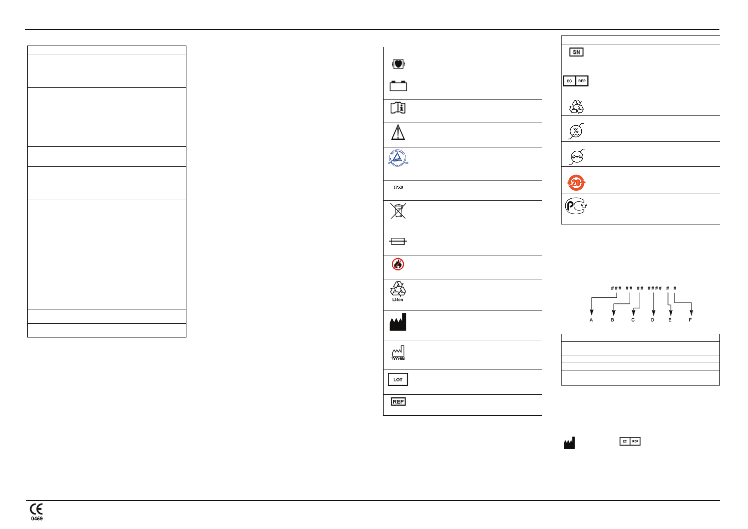
EQUIPMENT SYMBOLS
Symbol Description/Function
Type CF equipment. The acquisition module is protected
from defibrillation shocks.
The flashing yellow LED indicates you must connect to AC
power to re-charge the battery.
Consult instructions for use.
Consult accompanying documents for cautions.
Classified with respect to electric shock, fire, mechanical, and
other specified hazards only in accordance with UL 60601-1,
CAN/CSA C22.2
No. 601.1, EN 60601-2-25, EN 60601-1, IEC 60601-1-2:
2001, IEC 60601-2-51.
Indicates that the device is classified as Ordinary Equipment
(enclosed equipment without protection against ingress of
water).
Indicates that the waste of electrical and electronic equipment
must not be disposed as unsorted municipal waste and must
be collected separately. Please contact an authorized
representative of the manufacturer for information concerning
the decommissioning of your equipment.
Fuse.
Do not throw or dispose of in fire!
Contains "Lithium Ion". This symbol indicates "General
recovery/recyclable" and must not be disposed of as unsorted
municipal waste and must be collected separately.
Manufacturer name and address.
Date of Manufacture (Year-Month).
Batch code of paper or battery.
Symbol Description/Function
Serial number.
European authorized representative.
The packaging of this product can be recycled.
Humidity limitation.
Atmospheric pressure limitation.
Environment-friendly Use Period per Chinese standard SJ/
T11363-2006 (China specific).
PCT. GOST marking symbolizing conformity with applicable
Russian Gosstandart technical and safety standards.
SERVICE REQUIREMENTS
Refer equipment servicing to GE authorized service personnel only. Any
unauthorized attempt to repair equipment under warranty voids that
warranty. It is the user’s responsibility to report the need for service to GE
or an authorized agent.
EQUIPMENT IDENTIFICATION
Every GE device has a unique serial number for identification on the
device label.
A Product code is SCT
B
C Fiscal week manufactured
D Production sequence number
E Manufacturing site
F Miscellaneous characteristic
Year manufactured (00-99)
00 = 2000, 01 = 2001, and so on
Catalogue number (Part number).
g
GE Medical Systems
Information
Technologies, Inc.
8200 West Tower
Avenue
Milwaukee, WI 53223 USA
Tel: + 1414 355 5000
1 800 558 5120 (US only)
Fax: + 1414 355 3790
www.gehealthcare.com
GE Medical Systems
Information Technologies
GmbH
Munzinger Strabe 3-5
D-79111 Freiburg
Germany
Tel: + 49 761 4543 - 0
Fax: + 49 761 4543 - 233
MAC™ 400 resting ECG analysis system guides 2 of 7
2032589-001 Revision E
Asian Headquarters
GE Medical Systems
Information Technologies Asia;
GE (China) Co., Ltd.
11th Floor Shanghai MAXDO
Centre
8 Xing Yi Road, Hong Qiao
Development Zone
Shanghai 200336, People’s
Republic of China
Tel: + 86-21-5257-4650
Page 3
MAC™ 400 Resting ECG Analysis System Installation and Setup Guide
© 2007, 2008 General Electric Company. All rights reserved.
The MAC™ 400 Resting ECG Analysis System Installation and Setup
Guide provides instructions for initial installation and setup of your
system.
Before you begin
Remove the device and accessories from the box, and keep on a flat dry
surface, away from direct sunlight, heat sources & dust.
A. Confirming the box contents
• MAC 400 resting ECG analysis device
• Four limb clamp electrodes
• Six bulb electrodes
• Patient ECG cables/lead wires
• Power cable
• Pack of z-fold paper (280 sheets)
• Electrode cream
• CD containing a service manual and 12SL™ Physicians Guide
• User guide
B. Charging the battery
The MAC 400 system needs a charged battery to print an ECG. Charge
the battery for three hours for full power. A fully charged battery
allows for 100 automatic mode ECGs or 100 minutes of arrhythmia/
manual mode recording.
1. Connect the device to a power source.
2. Turn on the power (a green light indicates that AC mains is
connected).
3. After charging for three hours, unplug the power cord from
both the device and the power source.
Recharge when you see a yellow light above the power key.
C. Loading paper
The MAC 400 system supports the use of standard thermal recording
paper in either z-fold pads or roll paper.
1. Locate the printer assembly.
2. Gently pull back the printer assembly door to open the door
latch.
A red line at the top of the last ten sheets indicates that the paper
supply is low. Change paper as needed.
NOTE: For instructions on loading roll paper, see the
“MAC™ 400 Resting ECG Analysis System Maintenance
Guide”.
Initial system setup
THE SETUP MENU
Press on/off to turn on the device, and then, press
configuration to access the setup menu. Use the setup menu to
navigate between system settings and select the options you want. For
more information, see System Symbols and System Menu Descriptions
on page 4.
THE SYSTEM PARAMETERS TOOLS
Use these tools and guidelines to help you define the operating parameters.
1. Use up/down cursor to select a menu item.
2. Use right/left cursor to select the desired setting.
3. Always press enter to confirm your selection.
4. Always press configuration to save and exit the
setup menu.
SETTING OPTIONS FOR INITIAL USE
A. Selecting a language
Different languages are available for the display text and printed ECG
reports.
1. Press configuration to display the language selection
menu.
2. Use the right/left cursor to select the language.
3. Press enter to confirm your selection.
B. Selecting the lead notations
There are two different lead notation options: AHA and IEC.
1. Use the up/down cursor to select Notation.
2. Use the right/left cursor to select AHA or IEC.
2. Use the right/left cursor to set the date.
3. Press enter to confirm your selection.
To set the time:
1. Use the up/down cursor to select Time.
2. Use the right/left cursor to set the time.
3. Press enter to confirm your selection.
D. Selecting heart rate limit values
1. Use the up/down cursor to select HR control. The
cursor flashes on the low limit value.
2. Use the right/left cursor to change the low limit
value, in increments of 5 BPM, between 30 and 120 BPM.
3. Press enter to confirm your selection.
4. Use right/left cursor, change the high-limit value
(between 80 and 240 BPM).
5. Press enter to confirm.
NOTE: After setting these options, you must press
configuration to save the options and exit the setup menu.
Heart rate indication
THE BASICS
WARNING PATIENT HAZARD — The MAC 400 system is not
intended for use as a vital signs physiological monitor. When needed,
use a device intended for vital signs monitoring.
When the heart rate indication function is enabled, the automatic switchoff
is disabled. Conditions of high and low heart rate are indicated in all
operating modes, even when not recording. This function can be disabled
in the setup menu. The default heart rate limits are 45 and 130 BPM, and
can be modified in the setup menu. If the heart rate exceeds one of the set
values, the system emits an audio signal. This audio signal ceases
automatically when the heart rate returns to the permitted range or when
you press QRS beep. The audio signal will not recur if it was
silenced with QRS beep. The audio signal recurs only when the
heart rate exceeds one of the limit values again.
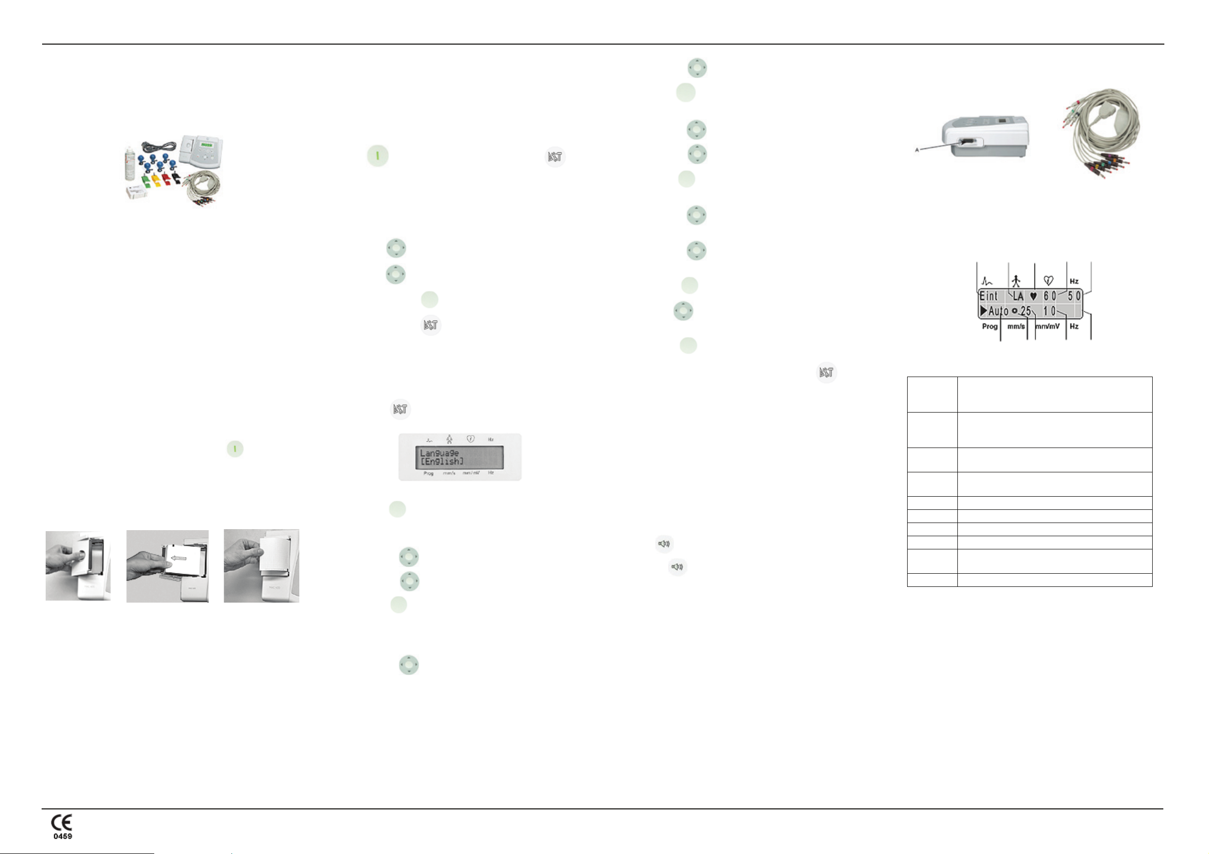
E. Hooking up the starter kit
Once you have customized your settings, connect the patient cable to
the device (A) on the right side panel.
Default settings for auto mode
When you turn on the device, the system default is automatic mode.
Factory defaults have the following functions and settings (the most
important settings are indicated on the display):
A
BC
J
I
H
Lead sequence: Standard = Einthoven (I, II, III),
A
Goldberger(aVR, aVL, aVF), Wilson 1 (V1, V2,
V3), Wilson 2 (V4, V5, V6).
Lead fail indicator: Indicates a disconnected
B
electrode. For example, LA indicates that the left
arm electrode is disconnected.
C
D
QRS indicator: The heart symbol blinks with every
detected systole.
Heart rate: Detects the patient’s heart rate. In this
example, it is 60 BPM.
E AC filter: On (enabled) (50 Hz).
F Muscle filter: Off (disabled).
G Sensitivity (gain): 10 mm/mV.
H Paper speed: 25 mm/s.
Rotating symbol: Displays when the ECG data
I
acquisition or recording is active.
J Operating mode: Automatic.
E
D
F
G
3. Open the z-fold paper pack.
4. Ensure that the black paper guide is on the top and place the
paper in the tray.
5. Advance the first sheet and close the door. Make sure that
the paper is positioned on the pressure roller and that the
door locks into place on both sides.
3. Press enter to confirm your selection.
C. Setting the date and time
Set the date and time for printed ECG reports.
To set the date:
1. Use the up/down cursor to select Date.
Additional default settings (not indicated on the display):
• Notation: AHA.
• ADS: Enabled.
• Report format: Simultaneous, short.
• Override: Disabled.
NOTE: For further descriptions of the settings, see System Menu
Descriptions on page 4.
MAC™ 400 resting ECG analysis system guides 3 of 7
2032589-001 Revision E
Page 4

MAC™ 400 Resting ECG Analysis System Installation and Setup Guide
© 2007, 2008 General Electric Company. All rights reserved.
System setup
The system setup function allows you to customize many of the MAC 400
system settings. Once you customize and save your settings, they will
activate each time you turn on the system.
System symbols
Symbol Description
ECG lead indicator.
Heart rate in beats per minute (BPM).
Lead fail indicator.
Hz (top) AC filter (line frequency) in Hertz (Hz).
Hz (bottom) Muscle filter in Hertz (Hz).
Prog Operating mode: manual, automatic or arrhythmia.
mm/s Paper speed in millimeters per second (mm/s).
mm/mV Sensitivity (gain) in millimeters per Millivolt (mm/mV).
Power key: press to turn on and off.
Cursor control keys: press to move the cursor up, down,
right or left to select menu items and change settings.
Enter key: press to confirm selections during device
configuration.
Start /Stop key: press to start or stop a recording.
Menu Item Options Description
Notation [AHA] IEC
Electrode designations:
AHA: RA, LA, RL, LL, V1 to
V6.
IEC: R, L, F, N, C1 to C6.
Lead
[Stand.] (Standard)
Cabr. (CABRERA)
Standard lead sequence:
I, II, III, aVR, aVL, aVF, V1 to
V6.
Cabrera lead sequence:
aVL, I, -aVR, II, aVF, III, V1
to V6.
Report format
[Sim]
(Simultaneous)
Seq (Sequential)
In automatic mode, the system
collects and saves 12 standard
leads for 10 seconds. The leads
are recorded in 4 groups of 3
leads each.
Report format
(simultaneous
reports only)
[Short] Long
All recorded leads reflect the
same period of time: long
format = 10 seconds, short
format = 3 seconds.
Rhythm recording
(sequential reports
only)
Ye s [ No ]
A recorded 10-second period is
divided into 4 segments
(quarters) of 2.5 seconds: The
first 3 leads reflect the first 2.5second quarter, the second
group reflects the second
quarter and so on. A 10-second
rhythm recording can be
added.
Override On [Off]
When enabled, the device
starts recording in automatic
mode, even if an electrode is
disconnected.
Menu Item Options Description
No. of leads
(manual mode)
Speed (in mm/s)
Sensitivity (Gain)
AC filter
(line frequency)
[3] 1
[25] 50
5 [10] 20
[50] 60
Off
Number of leads recorded in
manual mode: 1 or 3.
Paper speed: 25 or 50 mm/s.
5, 10 or 20 mm/mV.
Suppression of interference:
“50” for countries with 50-Hz
power line.
“60” for countries with 60-Hz
power line.
Muscle filter On [Off]
Filter frequency
20 [35]
(only if muscle
filter is ON)
Suppression of muscle artifact.
Selection of muscle filter
frequency. NOTE: filters may
suppress diagnostically
relevant portions of the signal.
Only enable filters when
necessary.
ADS (Anti Drift
System)
[On] Off
In case of wandering baselines,
restores the baseline to its
original position. ADS causes
a signal delay of 4 seconds.
Paper [F] R
F - fan-fold (z-fold) paper.
R - roll paper.
HR control [On] Off
Enables/disables the HR
indication function in
Automatic and Manual Mode.
If disabled, the MAC 400 turns
off when the system is idle for
5 minutes.
HR control
low limit and high
limit (in increments
of 5 BPM) high
limit must be at
least 5 BPM above
low limit)
[45] [130]
30 to 120 and 80 to
240
Selection of heart rate limit
values. Cursor left reduces the
value, cursor right increases it.
Low limit range: 30 to 120
BPM.
High limit range: 80 to 240
BPM.
Menu Item Options Description
Cut-off frequency
0.01 0.04
[0.08] 0.16
Selection of the lower cut-off
frequency of the signal
transmission range: 0.01, 0.04,
0.08 or 0.16 Hz.
Contrast
(increase) (decrease) Cursor right increases contrast.
Cursor left decreases contrast.
QRS beep Off [On]
If turned on, the system beeps
with every detected systole.
Date
Chinese language:
YYYY.MM.DD
All other languages:
Change the date. Adjust with
cursor right/left, press the
enter key to confirm and save.
DD.MMM.YYYY
Time
24-hour format e.g.
17:50 (HH:MM)
Adjust with cursor right/left,
press the enter key to confirm
and save.
Factory defaults
Ye s
No (default always
Select “Yes” to restore the
factory default settings.
remains as no)
Print configuration
list
Ye s
No (default always
Select “Yes” to print a list of
all device settings.
remains as no)
Lead selection key: press to change the ECG leads. The key
is only enabled when a patient cable is connected.
Copy key: press to print additional report copies.
QRS beep key: Press to enable/disable QRS beep and audio
signals alerting to specific events, and to clear the error
message.
Configuration key: press to access/quit setup menu.
System menu descriptions
NOTE: Angular brackets [ ] identify default setting.
Menu Item Options Description
Language
[English]/Chinese/
French/Dutch/
Italian/Spanish/
Portuguese/Russian/
Polish/Czech/
Hungarian/German
Select a language for the
display and printed reports.
NOTE: When you choose
Chinese or Russian, changes
only affect printed reports. The
display remains in English.
g
GE Medical
Systems
Information
Technologies, Inc.
8200 West Tower Avenue
Milwaukee, WI 53223 USA
Tel: + 1414 355 5000
1 800 558 5120 (US only)
Fax: + 1414 355 3790
www.gehealthcare.com
GE Medical Systems
Information Technologies
GmbH
Munzinger Strabe 3-5
D-79111 Freiburg
Germany
Tel: + 49 761 4543 - 0
Fax: + 49 761 4543 - 233
Asian Headquarters
GE Medical Systems
Information Technologies
Asia; GE (China) Co., Ltd.
11th Floor Shanghai
MAXDO Centre
8 Xing Yi Road, Hong Qiao
Development Zone
Shanghai 200336, Peopl e’s
Republic of China
Tel: + 86-21-5257-4650
MAC™ 400 resting ECG analysis system guides 4 of 7
2032589-001 Revision E
Page 5

MAC™ 400 Resting ECG Analysis System Operator Guide
© 2007, 2008 General Electric Company. All rights reserved.
The MAC™ 400 Resting ECG Analysis System Operator Guide
provides instructions for using the device to record ECGs.
Before recording an ECG, you must prepare the patient and set up the
electrode and lead wire connections.
A. Prepping the patient’s skin
Prep the skin to help ensure an interference-free ECG. To prep the skin:
1. Shave hair from the area and degrease each electrode site
with alcohol.
2. Use an abrasive pad or skin prep cream to remove the
epidermal skin layer at each site.
B. Applying electrodes
Apply electrode cream or gel to the electrode sites and attach the
suction bulbs (or optional disposable electrodes) at each site. In
situations where hair is present, electrode cream or gel helps to seal the
electrodes. If using electrode paper, moisten it with water and apply it
to the patient’s skin at the application points.
Apply a small amount of electrode cream or gel to the metal electrode
of each clamp. Apply the clamp electrodes to the limbs as indicated in
the Electrode Placement table.
C. Recording standard leads
Four limb and six chest electrodes must be applied to the patient for
acquisition of the standard leads I, II, III, aVR, aVL, aVF, and V1/C1
to V6/C6. Connect the six bulb electrodes to the chest lead wires and
the four clamp electrodes to the limb lead wires.
D. Connecting the lead wires (as indicated)
To chest leads
E. Arranging the patient cable (as shown)
ELECTRODE PLACEMENT
This table explains the location of each placement and identifies the labels
for AHA or IEC notations.
AHA Label IEC Label Electrode Placement
V1 red C1 red Fourth intercostal space at the right sternal
border.
V2 yellow C2 yellow Fourth intercostal space at the left sternal
border.
V3 green C3 green Midway between C2/V2 and C4/V4.
V4 blue C4 brown Mid-clavicular line in the fifth intercostal
space.
V5 orange C5 black Anterior auxiliary line on the same horizontal
level as C4/V4.
V6 purple C6 purple Mid-auxiliary line on the same horizontal
level as C4/V4 and C5/V5.
LA black L yellow Above left wrist (alternate placement: left
deltoid).
LL red F green Above left ankle (alternate placement: upper
leg close to torso).
RL green N black Above right ankle (alternate placement:
upper leg close to torso).
RA white R red Above right wrist (alternate placement: right
deltoid).
NOTE: Alternate placements apply when using disposable
electrodes.
F. Recording an ECG in all operating modes
1. Turn on the device and wait for the self-test to end.
2. Apply all electrodes to the patient and connect the patient
cable to the device.
3. Using the cursor keys, select the operating mode:
Automatic, Manual or Arrhythmia.
4. Check the device settings:
• Lead (standard, CABRERA)
• Speed (50, 25 mm/s (5 mm/s for manual and arrhythmia
modes))
• Sensitivity (gain) (20, 10, 5 mm/mV)
• Muscle filter (off, 20/35 Hz)
• AC filter (on, off)
5. If required, use the lead selection to change the lead/
lead group or the cursor keys to modify other settings.
NOTE: For details on changing settings, see the MAC™ 400
Installation and Setup Guide.
6. Wait for the patient to lie motionless and press start/
stop to initiate signal acquisition and recording.
Operating modes
The MAC 400 system has three operating modes for recording ECGs.
Once you determine the mode you want to use and adjust the settings,
follow the operating instructions.
NOTE: The factory default sets the heart rate (HR) indication
function active in all operating modes. The default HR limits are 45
BPM and 130 BPM. These limits can be changed from the setup
menu. At least four QRS complexes are required for correct
determination of the heart rate.
AUTOMATIC MODE
The default operating mode for the system is automatic mode. When
initiated in automatic mode, the system simultaneously acquires 12 leads of
ECG for a period of 10 seconds and then recording proceeds automatically.
The system measures the ECG and records the results on a report. You can
choose between simultaneous and sequential report formats:
• Simultaneous format records all leads representing the same period
of time (either 10 seconds = long format, or 3 seconds = short
format).
• For sequential recordings, the 10-second signal acquisition period
is divided into four segments of 2.5 seconds each. The first three
recorded leads represent the first segment (0-2.5 seconds), the
second group of leads represents the second segment, and so on.
You may also choose to record a 10-second rhythm strip.
You may choose standard or CABRERA lead sequence recordings. The
factory default records all 12 leads simultaneously on four sheets, each
representing a period of 3 seconds.
To print a duplicate report, press the copy key. Before printing the
copy, you may change the speed, gain, leads and report format.
NOTE: If lead failure occurs, the system will operate in automatic
mode only if the override function is enabled in the setup menu.
MANUAL MODE
In manual mode, the system simultaneously records 1 or 3 (default) leads
of ECG in real-time.
ARRHYTHMIA MODE
In arrhythmia mode, the system continuously scans the ECG and initiates a
recording. Specific conditions trigger the recording, which continues as
long as the condition(s) exist. These recordings include a 5-second period
before the event. The first 30 seconds are recorded at the selected paper
speed, then at 5 mm/s. When the start/stop key is pressed, the system
prints two pages and then checks for conditions.
Conditions that initiate a recording are:
• A heart rate exceeding one of the set limit values.
• QRS complexes with an RR interval shorter than 0.8 times or
greater than 1.5 times the RR interval averaged over the 4
preceding RR intervals.
Between events, you may initiate a 10-second recording with the
copy key.
NOTE: In arrhythmia mode, the heart rate indication function is
always active and cannot be disabled. Silence the audio signal
emitted when the heart rate exceeds either limit by pressing
QRS beep.
NOTES FOR MANUAL AND ARRHYTHMIA MODE ECGS
The following conditions apply to the system when operating in either
manual or arrhythmia mode.
• If you change the paper speed, gain, lead group or filter settings
during a recording, the system briefly stops, advances the paper to
the next fold or a few millimeters and then resumes recording.
These settings can not be changed for the first two pages of recording in
arrhythmia mode.
• Information can be lost following a change of device settings.
• If the ADS (Anti-Drift System) is enabled, there is a short delay to
activate this function before recording starts.
Report documents
The length and scope of the reports can vary depending on the operating
mode and selected lead and report format.
MEASUREMENT RESULTS
Following the ECG recording, the system prints one page of measurement
results including patient information and recording details.
INTERPRETIVE STATEMENTS (OPTIONAL)
With the interpretive statements option active, the system prints an
interpretive statement after the measurement results. Since it is not possible
to enter a patient’s age, the data is interpreted as an adult ECG.
For a detailed description of the ECG measurement and interpretation
program, refer to the 12SL™ Physician’s Guide.
g
GE Medical Systems
Information
Technologies, Inc.
8200 West Tower Avenue
Milwaukee, WI 53223 USA
Tel: + 1414 355 5000
1 800 558 5120 (US only)
Fax: + 1414 355 3790
www.gehealthcare.com
GE Medical Systems
Information Technologies
GmbH
Munzinger Strabe 3-5
D-79111 Freiburg
Germany
Tel: + 49 761 4543 - 0
Fax: + 49 761 4543 - 233
Asian Headquarters
GE Medical Systems
Information Technologies Asia;
GE (China) Co., Ltd.
11th Floor Shanghai MAXDO
Centre
8 Xing Yi Road, Hong Qiao
Development Zone
Shanghai 200336, People’s
Republic of China
Tel: + 86-21-5257-4650
MAC™ 400 resting ECG analysis system guides 5 of 7
2032589-001 Revision E
Page 6

MAC™ 400 Resting ECG Analysis System Maintenance Guide
© 2007, 2008 General Electric Company. All rights reserved.
The MAC™ 400 Resting ECG Analysis System Maintenance Guide
provides maintenance and troubleshooting details for the device.
Cleaning and disinfecting exterior surfaces
Clean and disinfect exterior surfaces monthly, or more often as needed. To
clean exterior surfaces:
1. Use a clean, soft cloth and an agent or disinfectant that
contains alcohol and is commonly used in hospitals.
NOTE: Do not use disinfectants with a phenol base or peroxide
compounds.
2. Wring excess water/solution from the cloth. Do NOT drip
water or any liquid on the device and avoid open vents,
plugs, or connectors.
3. Dry surfaces with a clean cloth or paper towel.
Patient cables and lead wires maintenance
Clean and disinfect cables and lead wires as specified and depending on
activity.
CLEANING AND DISINFECTING PATIENT CABLES AND LEAD
WIRES
1. Remove cables and lead wires from the system before
cleaning.
2. Avoid pulling long wires from connector ends. Metal
connections can be pulled away from the connectors.
3. To clean cables and lead wires, wipe using a lightly
moistened cloth with mild soap and water. Then, wipe off
excess moisture and allow to air dry.
CAUTION: EQUIPMENT DAMAGE, SIGNAL DETERIORATION — Any contact of disinfectant solutions with metal
parts may cause corrosion. Avoid using disinfectant solution
around the metal parts.
4. To disinfect cables and lead wires, wipe exterior with a soft,
lint-free cloth. Use the following solution as recommended
in the APIC Guidelines for Selection and Use of
Disinfectants (1996):
• Sodium hypochlorite (5.2% household bleach)
minimum 1:500 dilution (minimum 100 ppm free
chlorine) and maximum 1:10 dilution.
• Any sodium hypochlorite wipe product that meets the
above guidelines can be used.
NOTE: Wring excess disinfectant from the cloth before using.
5. Wipe off cleaning solutions with a clean, lightly-moistened
cloth.
6. Dry thoroughly with a dry, lint-free cloth and let air dry for
at least 30 minutes.
connection pins.
Do not to let liquid “pool” around the
NOTE: Drying times may vary based on environmental conditions.
Do NOT use excessive drying techniques, such as oven, forced heat
or sun drying.
STORING CABLES AND LEAD WIRES
• Store in a dry well-ventilated area.
• Vertically hang cables and lead wires.
• Do not coil lead wires or cables tightly around the device.
CLEANING AND DISINFECTING ELECTRODES
Clean reusable electrodes immediately after use on a patient.
1. Peel off the adhesive foil before cleaning the electrodes (any
extra adhesive can be removed with benzene).
2. Use warm water and a small brush to remove cream or gel.
Do not use pointed or sharp objects for cleaning.
3. Disinfect the electrodes with alcohol-free disinfectant.
Ensure that connectors and sockets do not get wet.
NOTE: Discard disposable adhesive electrodes immediately after
use. Do NOT reuse.
STERILIZING ELECTRODES
The only approved sterilization method is gas sterilization.
Sterilize with ethylene oxide gas (EtO) at a maximum temperature of 50°
C/122° F. After EtO sterilization, follow the manufacturer’s
recommendations for required aeration.
NOTE: Frequent sterilization reduces the useful life of cables and
lead wires.
Printer maintenance
CLEANING THE PRINTHEAD
If the printer is not functioning properly, you may need to clean dust and
foreign particles from the printhead. To clean the printhead:
1. Separate the platen from the printer.
2. Gently wipe off the heating element part of the surface with
cotton swabs and ethyl alcohol.
3. Replace the platen when it is completely dry.
NOTE: Do not use products that can harm the heating element, such
as sandpaper. Avoid unnecessary force when handling the printhead.
REPLACING PAPER
The MAC 400 system uses z-fold writer paper pads. Optional roll paper
can be ordered.
NOTE: Use only original GE writer paper.
This paper has a special coating that prevents contamination and debris
collection on the printhead, and electrostatic buildup.
The thermosensitive layer and the printhead characteristics are exactly
matched.
Using other paper may result in recordings of poor quality. The printhead
may wear out prematurely, and use of other paper may void the warranty.
CAUTION: RISK OF SKIN BURNS — The printhead gets hot
when recording. Do not to touch the thermal printhead when
inserting the paper.
INSTALLING ROLL PAPER
The MAC 400 system comes with z-fold paper, but you can use the
approved roll paper.
NOTE: You must change the system settings from z-fold to roll
paper.
1. Open the printer door, locate the spindle and remove any
leftover paper.
2. Slide the paper roll onto the spindle.
3. Place the roll, with the print side (red grid) facing the
thermal printhead, into the compartment by fitting the
spindle into the grooves on either side.
4. Unroll the beginning of the paper and close the door. Make
sure that the paper is exactly positioned on the pressure
roller and that the door locks into place on both sides.
STORING THERMAL PAPER
NOTE: To ensure maximum image life, store thermal paper
separately in manila folders or polyester/polymide protectors.
To avoid deterioration or fading, follow these precautions:
1. Store in cool, dark, and dry locations. Temperature must be
below 86°F (30°C). Relative humidity must be less than
(<)65%.
2. Avoid exposure to bright light or ultraviolet sources such as
sunlight, fluorescent, and similar lighting which causes
yellowing and fading.
3. Do NOT store thermal papers with any of the following:
• Carbon and carbonless forms.
• Non-thermal papers or any products containing tributyl
phosphate, dibutyl phthalate, or other organic solvents.
Many medical and industrial writer papers contain
these chemicals.
• Document protectors, envelopes, and sheet separators
containing polyvinyl chloride or other vinyl chlorides.
4. Avoid contact with: cleaning fluids and solvents such as
alcohols, ketones, esters, ether, etc.
5. Do NOT use: mounting forms, pressure-sensitive tapes, or
labels containing solvent-based adhesives.
Technical inspection
For safety, the equipment requires regular maintenance. To ensure
functional and operational safety of the device, technical inspections
should be performed annually by persons with adequate training and
experience.
These checks can be carried out by GE within the framework of a service
contract.
Inspections include the following checks:
• Visual inspection of equipment and accessories for signs of
mechanical damage that may impair the device functions.
• Visual inspection of the device labeling for legibility.
• Functional test as described in the service manual.
• Measurement of the resistance of the non-fused, earthed conductor
and the equivalent leakage current as per local regulations.
NOTE: The device does not require any other maintenance.
Order information
Always refer to the most recent list of accessories. For a complete list
of MAC 400 system supplies and accessories, go to
www.gehealthcare.com.
Disposal of the product
The product described in this guide must not be disposed as unsorted
municipal waste and must be collected separately. Please contact an
authorized representative of the manufacturer for information concerning
the decommissioning of your equipment.
WARNING: EXPLOSION HAZARD —
Batteries may explode in fires. Do not dispose of the battery by
fire or burning.
Follow local environmental guidelines concerning disposal and
recycling.
Error messages
Message Cause Solution
Paper Error
Door Open
Battery Error
ATTENTION!!!
Overtemperature
Test failed!
CODE: 1
VECTOR
Test failed!
CODE: 2 RAM
Test failed!
CODE: 4 ROM
Test failed!
CODE: 5 DSP
The system is out of
paper.
Paper jam.
Wrong paper type
inserted (z-fold/roll).
Printer door not
closed properly.
Battery not present.
Battery not
functioning properly.
The printer
mechanism has
heated up due to
heavy use.
Power on self-test
failed.
Power on self-test
failed.
Power on self-test
failed.
Power on self-test
failed.
Check paper supply.
Remove jammed paper.
Set up the system for correct
paper type.
Clear message with
Close printer door correctly.
Clear message with .
Check for battery. Check that
contacts are clean. Notify
service to check and replace the
battery.
Clear message with
Turn off device and power on
after 3 to 4 minutes. If problem
recurs with normal use, notify
service.
Contact service and have device
repaired before using it again.
Contact service and have device
repaired before using it again.
Contact service and have device
repaired before using it again.
Contact service and have device
repaired before using it again.
MAC™ 400 resting ECG analysis system guides 6 of 7
2032589-001 Revision E
Page 7
MAC™ 400 Resting ECG Analysis System Maintenance Guide
© 2007, 2008 General Electric Company. All rights reserved.
Troubleshooting tips
These errors may occur while operating this system. If you perform the
recommended actions and the condition remains, contact GE Service for
assistance.
Problem Cause Solution
Periodic
superimposition of AC
line interface (50/60
Hz) (See Figure 2)
Superimposition of
irregular interference
signals (See Figure 1)
The printed date and
time are incorrect.
The green LED does
not light up, although
the recorder is
connected to the
power line.
Recorder does not
write over the entire
paper.
No paper transport
after activation of an
operating mode or the
recorder does not stop
and continues to feed
paper.
Improper printing Adhesion of dust and
Battery error Internal system
Interference from the
power line
Muscle artifact caused
by patient movements,
hiccup, coughing
Built-in lithium ion
battery is depleted. The
battery has a life of
approximately 5 years.
Defective AC power
adapter or fuse.
Paper compartment not
properly closed.
The paper pad was
inserted in the wrong
direction, so that the
cue marker cannot be
identified.
foreign materials to
paper can deteriorate
the life of the printer
head and plate.
temperature may be
higher than the
recommended battery
charging range.
Ground bed, verify
position of the lead wires,
switch on the AC filter.
The patient should be
warm and resting
comfortably (place
cushions under arms and
knees). Enable muscle
filter (20 Hz/35 Hz), if
necessary.
Notify service to check
the battery.
Notify service to check
the fuses.
Printer door must lock
into place on both sides.
Insert the paper pad as
instructed in the MAC
400 Resting ECG
Analysis System
Installation and Setup
Guide.
Clean the printhead as
indicated in this guide.
Switch off the mains and
restart recording in
battery mode.
(We recommend
recording ECGs in
battery mode and
charging the battery when
the system is not in use.)
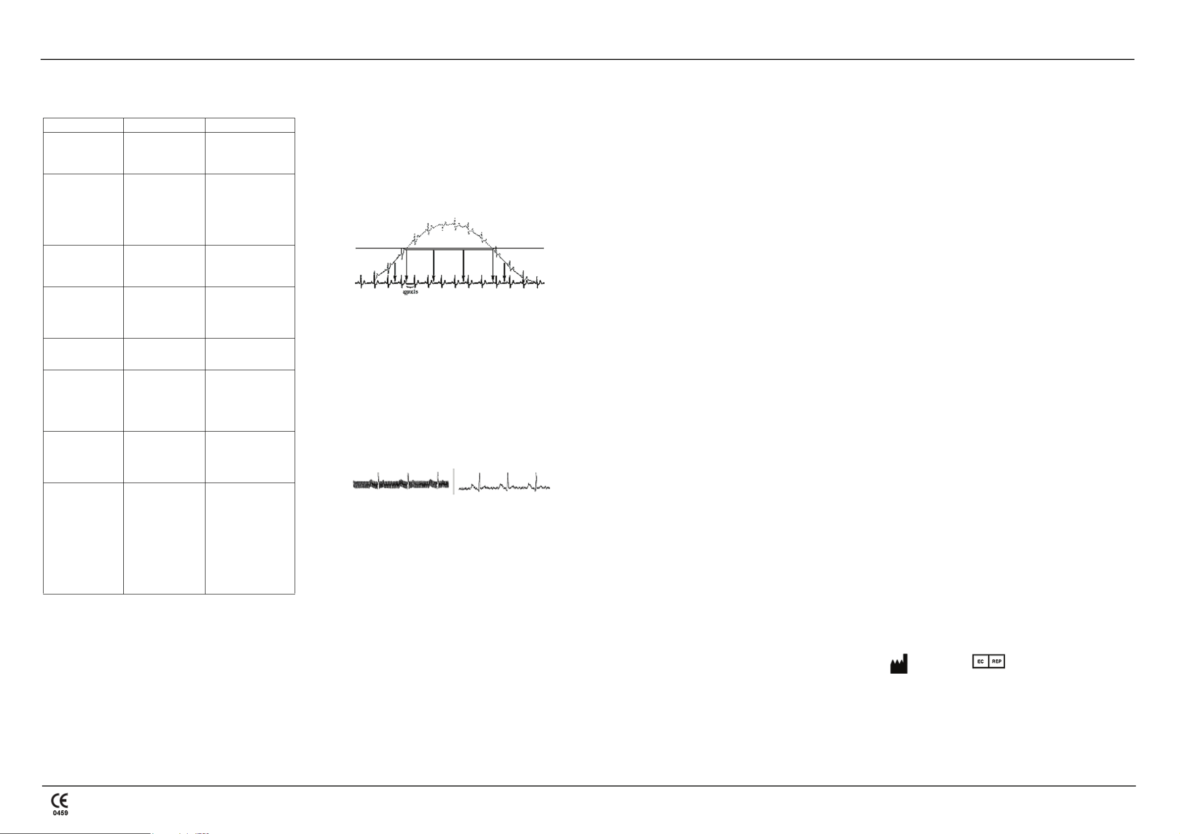
BASELINE ROLL
PROBLEM
The MAC 400 system is equipped with automatic baseline adjustment and
anti-drift system (ADS) to ensure artifact-free recording. At the beginning
of the recording the automatic baseline adjustment verifies the incoming
signal and adjusts the baseline position accordingly. During recording, the
anti-drift system continuously checks the baseline position and returns the
baseline to its normal level (See Figure 1).
If electrodes are not properly applied, these measures may not fully
compensate for artifact. Electrodes applied without conductive gel may
induce high polarization voltages that can cause the amplifier to overrange.
A straight line is recorded instead of the ECG (see Figure 1). ADS returns
this line to its normal position, and a baseline ensues for approximately one
second.
figure 1
SOLUTION
• Apply the electrodes according to instructions.
• Do not apply the electrodes on top of clothing.
• Use a contact agent (moist electrode paper, electrode cream, spray,
etc.).
• Wait approximately 10 seconds before initiating a recording.The
polarization voltages stabilize if the electrodes are properly applied.
If not, the electrode concerned is indicated on the display (R/RA, L/
LA, F/LL, C1/V1 to C6/V6).
NOTE: The system does not support lead fail indication for the N/
RL electrode. If the ECG is extremely noisy, the N/RL electrode may
not be properly connected. Check and reconnect.
If it becomes necessary to verify the raw ECG signal, switch off the ADS
function and all filters (35 Hz/20 Hz muscle filter, AC filter). Activate the
AC line filter (50 Hz/60 Hz) in the presence of strong AC line interference.
figure 2
Faulty battery
Notify service to check
the battery.
g
GE Medical
Systems
Information
Technologies, Inc.
8200 West Tower Avenue
Milwaukee, WI 53223 USA
Tel: + 1414 355 5000
1 800 558 5120 (US only)
Fax: + 1414 355 3790
www.gehealthcare.com
GE Medical Systems
Information Technologies
GmbH
Munzinger Strabe 3-5
D-79111 Freiburg
Germany
Tel: + 49 761 4543 - 0
Fax: + 49 761 4543 - 233
MAC™ 400 resting ECG analysis system guides 7 of 7
2032589-001 Revision E
Asian Headquarters
GE Medical Systems
Information Technologies
Asia; GE (China) Co., Ltd.
11th Floor Shanghai
MAXDO Centre
8 Xing Yi Road, Hong Qiao
Development Zone
Shanghai 200336, People’s
Republic of China
Tel: + 86-21-5257-4650
 Loading...