

Page 1

GE Healthcare
MACTM 3500
Resting ECG Analysis System
Version 9D
Service Manual
2021337-036 Revision L
Page 2

The information in this manual applies only to MACTM 3500 Resting ECG Analysis Systems with product code SCA. It does
not apply to earlier software versions. Due to continuing product innovation, specifications in this manual are subject to
change without notice.
MUSE ,CASE, MAC, MARS, MULTI-LINK, and 12SL are trademarks owned by GE Medical Systems Information
Technologies, Inc., a General Electric Company going to market as GE Healthcare. All other trademarks are owned by their
respective owners.
© 2005-2008, 2010, 2013, 2014, 2019
T-2 MAC™ 3500 Resting ECG Analysis System
2021337-036
Revision L
15 February 2019
Page 3

Contents
1 Introduction
Manual Information . . . . . . . . . . . . . . . . . . . . . . . . . . . . . . . . . . . . . . . . . . . . . . . . . . 1-3
Revision History . . . . . . . . . . . . . . . . . . . . . . . . . . . . . . . . . . . . . . . . . . . . . . . 1-3
Manual Purpose . . . . . . . . . . . . . . . . . . . . . . . . . . . . . . . . . . . . . . . . . . . . . . .1-3
Intended Audience . . . . . . . . . . . . . . . . . . . . . . . . . . . . . . . . . . . . . . . . . . . . . 1-3
Related Documentation . . . . . . . . . . . . . . . . . . . . . . . . . . . . . . . . . . . . . . . . . 1-4
Warnings, Cautions, and Notes . . . . . . . . . . . . . . . . . . . . . . . . . . . . . . . . . . . . . . . . 1-4
Safety Messages . . . . . . . . . . . . . . . . . . . . . . . . . . . . . . . . . . . . . . . . . . . . . . . . . . . . 1-5
Responsibility of the Manufacturer . . . . . . . . . . . . . . . . . . . . . . . . . . . . . . . . . 1-5
General . . . . . . . . . . . . . . . . . . . . . . . . . . . . . . . . . . . . . . . . . . . . . . . . . . . . .1-6
Equipment Symbols . . . . . . . . . . . . . . . . . . . . . . . . . . . . . . . . . . . . . . . . . . . . . . . . . 1-7
Service Information . . . . . . . . . . . . . . . . . . . . . . . . . . . . . . . . . . . . . . . . . . . . . . . . . . 1-9
Service Requirements . . . . . . . . . . . . . . . . . . . . . . . . . . . . . . . . . . . . . . . . . . 1-9
Equipment Identification . . . . . . . . . . . . . . . . . . . . . . . . . . . . . . . . . . . . . . . . . 1-9
Serial Number Format . . . . . . . . . . . . . . . . . . . . . . . . . . . . . . . . .1-10
Label Format . . . . . . . . . . . . . . . . . . . . . . . . . . . . . . . . . . . . . . . . 1-10
2 Equipment Overview
General Description . . . . . . . . . . . . . . . . . . . . . . . . . . . . . . . . . . . . . . . . . . . . . . . . . . 2-3
Side View . . . . . . . . . . . . . . . . . . . . . . . . . . . . . . . . . . . . . . . . . . . . . . . . . . . . 2-3
Back View . . . . . . . . . . . . . . . . . . . . . . . . . . . . . . . . . . . . . . . . . . . . . . . . . . .2-4
Connector Identification . . . . . . . . . . . . . . . . . . . . . . . . . . . . . . . . . . . . . . . . . . . . . . 2-5
3 Installation
Introduction . . . . . . . . . . . . . . . . . . . . . . . . . . . . . . . . . . . . . . . . . . . . . . . . . . . . . . . . 3-3
General Assembly . . . . . . . . . . . . . . . . . . . . . . . . . . . . . . . . . . . . . . . . . . . . . . . . . . . 3-4
Trolley Height Adjustment . . . . . . . . . . . . . . . . . . . . . . . . . . . . . . . . . . . . . . .3-6
Installing the MAC™ 3500 Resting ECG Analysis System . . . . . . . . . . . . . .3-8
Installing the Optional External Modem Kit . . . . . . . . . . . . . . . . . . . . . . . . . 3-10
Magnetic Card Reader Installation . . . . . . . . . . . . . . . . . . . . . . . . . . . . . . . . 3-12
Barcode Reader Installation . . . . . . . . . . . . . . . . . . . . . . . . . . . . . . . . . . . . . 3-14
Revision L MAC™ 3500 Resting ECG Analysis System i
2021337-036
Page 4

4 Troubleshooting
Assembly Descriptions . . . . . . . . . . . . . . . . . . . . . . . . . . . . . . . . . . . . . . . . . . . . . . . 4-3
PCB Block Diagram . . . . . . . . . . . . . . . . . . . . . . . . . . . . . . . . . . . . . . . . . . . .4-3
Connection Diagrams . . . . . . . . . . . . . . . . . . . . . . . . . . . . . . . . . . . . . . . . . . . 4-5
LED/LVDS Display Assembly Diagram . . . . . . . . . . . . . . . . . . . . . . . . . . . . .4-6
Item . . . . . . . . . . . . . . . . . . . . . . . . . . . . . . . . . . . . . . . . . . . . . . . . . . . . . . . .4-6
General Fault Isolation . . . . . . . . . . . . . . . . . . . . . . . . . . . . . . . . . . . . . . . . . . . . . . . 4-7
Power-up Self-test . . . . . . . . . . . . . . . . . . . . . . . . . . . . . . . . . . . . . . . . . . . . . 4-7
Power-up Flow Chart . . . . . . . . . . . . . . . . . . . . . . . . . . . . . . . . . . . . . . . . . . .4-8
Poor Quality ECGs . . . . . . . . . . . . . . . . . . . . . . . . . . . . . . . . . . . . . . . . . . . . .4-9
Visual Inspection . . . . . . . . . . . . . . . . . . . . . . . . . . . . . . . . . . . . . . . . . . . . .4-10
Diagnostic Tests . . . . . . . . . . . . . . . . . . . . . . . . . . . . . . . . . . . . . . . . . . . . . . . . . . . 4-11
Loading the System Diagnostics Menu . . . . . . . . . . . . . . . . . . . . . . . . . . . .4-11
Display Test . . . . . . . . . . . . . . . . . . . . . . . . . . . . . . . . . . . . . . . . . 4-12
Speaker Test . . . . . . . . . . . . . . . . . . . . . . . . . . . . . . . . . . . . . . . .4-13
Keyboard Test . . . . . . . . . . . . . . . . . . . . . . . . . . . . . . . . . . . . . . .4-13
Trim Pad Control Test . . . . . . . . . . . . . . . . . . . . . . . . . . . . . . . . .4-14
Writer Test . . . . . . . . . . . . . . . . . . . . . . . . . . . . . . . . . . . . . . . . . .4-14
Battery Test . . . . . . . . . . . . . . . . . . . . . . . . . . . . . . . . . . . . . . . . .4-16
Communication Test . . . . . . . . . . . . . . . . . . . . . . . . . . . . . . . . . . .4-18
Acq. Module Tests . . . . . . . . . . . . . . . . . . . . . . . . . . . . . . . . . . . . 4-21
Analog I/O Tests . . . . . . . . . . . . . . . . . . . . . . . . . . . . . . . . . . . . . . 4-22
Floppy Drive Tests . . . . . . . . . . . . . . . . . . . . . . . . . . . . . . . . . . . .4-24
Internal Memory Tests . . . . . . . . . . . . . . . . . . . . . . . . . . . . . . . . . 4-25
SD Card Tests . . . . . . . . . . . . . . . . . . . . . . . . . . . . . . . . . . . . . . .4-25
Substitute Master Password . . . . . . . . . . . . . . . . . . . . . . . . . . . . . 4-26
Equipment Problems . . . . . . . . . . . . . . . . . . . . . . . . . . . . . . . . . . . . . . . . . . . . . . . . 4-27
ECG Data Noise . . . . . . . . . . . . . . . . . . . . . . . . . . . . . . . . . . . . . . . . . . . . . . 4-27
System Errors . . . . . . . . . . . . . . . . . . . . . . . . . . . . . . . . . . . . . . . . . . . . . . . . . . . . . . 4-28
Frequently Asked Questions . . . . . . . . . . . . . . . . . . . . . . . . . . . . . . . . . . . . . . . . . 4-29
Maintenance . . . . . . . . . . . . . . . . . . . . . . . . . . . . . . . . . . . . . . . . . . . . . . . . . 4-29
Save Setups . . . . . . . . . . . . . . . . . . . . . . . . . . . . . . . . . . . . . . . . .4-29
Storing ECGs . . . . . . . . . . . . . . . . . . . . . . . . . . . . . . . . . . . . . . . .4-29
Format an SD Card . . . . . . . . . . . . . . . . . . . . . . . . . . . . . . . . . . .4-29
Cleaning . . . . . . . . . . . . . . . . . . . . . . . . . . . . . . . . . . . . . . . . . . . .4-29
Battery Capacity . . . . . . . . . . . . . . . . . . . . . . . . . . . . . . . . . . . . . .4-30
System Setup . . . . . . . . . . . . . . . . . . . . . . . . . . . . . . . . . . . . . . . . . . . . . . . .4-30
Location Number . . . . . . . . . . . . . . . . . . . . . . . . . . . . . . . . . . . . .4-30
Patient Questions . . . . . . . . . . . . . . . . . . . . . . . . . . . . . . . . . . . . .4-30
Passwords . . . . . . . . . . . . . . . . . . . . . . . . . . . . . . . . . . . . . . . . . .4-31
Clinical . . . . . . . . . . . . . . . . . . . . . . . . . . . . . . . . . . . . . . . . . . . . . . . . . . . . . 4-31
Report Format . . . . . . . . . . . . . . . . . . . . . . . . . . . . . . . . . . . . . . .4-31
ii MAC™ 3500 Resting ECG Analysis System Revision L
2021337-036
Page 5

Editing . . . . . . . . . . . . . . . . . . . . . . . . . . . . . . . . . . . . . . . . . . . . .4-31
Entering Patient Data . . . . . . . . . . . . . . . . . . . . . . . . . . . . . . . . . . 4-32
Transmission . . . . . . . . . . . . . . . . . . . . . . . . . . . . . . . . . . . . . . . . . . . . . . . . 4-32
Losing Fields When Transmitting . . . . . . . . . . . . . . . . . . . . . . . . .4-32
Input and Output Connectors . . . . . . . . . . . . . . . . . . . . . . . . . . . . . . . . . . . . . . . . . 4-33
A Pins (J1) . . . . . . . . . . . . . . . . . . . . . . . . . . . . . . . . . . . . . . . . . . . . . . . . . . 4-33
COM1 (COM3/4) Pins (J3) . . . . . . . . . . . . . . . . . . . . . . . . . . . . . . . . . . . . . . 4-33
COM2 Pins (J5) . . . . . . . . . . . . . . . . . . . . . . . . . . . . . . . . . . . . . . . . . . . . . . 4-34
Analog Pins (J6) . . . . . . . . . . . . . . . . . . . . . . . . . . . . . . . . . . . . . . . . . . . . . . 4-34
EXT. VID. Pins (J7) . . . . . . . . . . . . . . . . . . . . . . . . . . . . . . . . . . . . . . . . . . .4-35
CPU PCB Input/Output Signals . . . . . . . . . . . . . . . . . . . . . . . . . . . . . . . . . . . . . . . 4-36
Battery Pack/Monitor, J2 . . . . . . . . . . . . . . . . . . . . . . . . . . . . . . . . . . . . . . .4-36
LCD Backlight, J4 . . . . . . . . . . . . . . . . . . . . . . . . . . . . . . . . . . . . . . . . . . . . . 4-36
Keyboard, J8 . . . . . . . . . . . . . . . . . . . . . . . . . . . . . . . . . . . . . . . . . . . . . . . .4-36
LCD, J10 . . . . . . . . . . . . . . . . . . . . . . . . . . . . . . . . . . . . . . . . . . . . . . . . . . . 4-37
Power Supply/Motor, J11 . . . . . . . . . . . . . . . . . . . . . . . . . . . . . . . . . . . . . . .4-38
Thermal Printer, J12 . . . . . . . . . . . . . . . . . . . . . . . . . . . . . . . . . . . . . . . . . . . 4-39
Floppy Disk Drive, J13 . . . . . . . . . . . . . . . . . . . . . . . . . . . . . . . . . . . . . . . . . 4-40
Acquisition Module, J14 . . . . . . . . . . . . . . . . . . . . . . . . . . . . . . . . . . . . . . . . 4-41
KISS Pump, J19 . . . . . . . . . . . . . . . . . . . . . . . . . . . . . . . . . . . . . . . . . . . . . . 4-41
Acquisition Module, J20 . . . . . . . . . . . . . . . . . . . . . . . . . . . . . . . . . . . . . . . . 4-41
LCD Backlight, J23 . . . . . . . . . . . . . . . . . . . . . . . . . . . . . . . . . . . . . . . . . . . . 4-42
5 Maintenance
Introduction . . . . . . . . . . . . . . . . . . . . . . . . . . . . . . . . . . . . . . . . . . . . . . . . . . . . . . . . 5-3
Recommended Maintenance . . . . . . . . . . . . . . . . . . . . . . . . . . . . . . . . . . . . . 5-3
Required Tools and Supplies . . . . . . . . . . . . . . . . . . . . . . . . . . . . . . . . . . . . .5-3
Inspection and Cleaning . . . . . . . . . . . . . . . . . . . . . . . . . . . . . . . . . . . . . . . . . . . . . . 5-4
Visual Inspection . . . . . . . . . . . . . . . . . . . . . . . . . . . . . . . . . . . . . . . . . . . . . .5-4
Exterior Cleaning . . . . . . . . . . . . . . . . . . . . . . . . . . . . . . . . . . . . . . . . . . . . . . 5-4
Interior Cleaning . . . . . . . . . . . . . . . . . . . . . . . . . . . . . . . . . . . . . . . . . . . . . . . 5-4
Checking Electrical Safety . . . . . . . . . . . . . . . . . . . . . . . . . . . . . . . . . . . . . . . . . . . . 5-5
FRU Replacement Procedures . . . . . . . . . . . . . . . . . . . . . . . . . . . . . . . . . . . . . . . . . 5-6
Disassembly Guidelines . . . . . . . . . . . . . . . . . . . . . . . . . . . . . . . . . . . . . . . . . 5-6
Battery Replacement . . . . . . . . . . . . . . . . . . . . . . . . . . . . . . . . . . . . . . . . . . . 5-6
Remove MAC 3500 System From Trolley . . . . . . . . . . . . . . . . . . . . . . . . . . . 5-7
Power Supply Replacement . . . . . . . . . . . . . . . . . . . . . . . . . . . . . . . . . . . . . . . . . . 5-10
General . . . . . . . . . . . . . . . . . . . . . . . . . . . . . . . . . . . . . . . . . . . . . 5-4
Thermal Printhead Cleaning . . . . . . . . . . . . . . . . . . . . . . . . . . . . . . 5-4
MAC Series Trolley . . . . . . . . . . . . . . . . . . . . . . . . . . . . . . . . . . . .5-7
Type-S Trolley . . . . . . . . . . . . . . . . . . . . . . . . . . . . . . . . . . . . . . . .5-8
Modular MAC Trolley . . . . . . . . . . . . . . . . . . . . . . . . . . . . . . . . . . . 5-9
Revision L MAC™ 3500 Resting ECG Analysis System iii
2021337-036
Page 6

Keypad Replacement . . . . . . . . . . . . . . . . . . . . . . . . . . . . . . . . . . . . . . . . . . . . . . . . 5-12
Keyboard/Top Cover Assembly Removal & Reassembly . . . . . . . . . . . . . . . . . . 5-14
Removal of Keyboard/Top Cover Assembly . . . . . . . . . . . . . . . . . . . . . . . .5-14
Replacing the LVDS Converter Board . . . . . . . . . . . . . . . . . . . . . . . . . . . . .5-16
Keyboard/Top Cover Assembly Reassembly . . . . . . . . . . . . . . .
Printhead Assembly Replacement . . . . . . . . . . . . . . . . . . . . . . . . . . . . . . . . . . . . . 5-18
Acquisition Board Replacement . . . . . . . . . . . . . . . . . . . . . . . . . . . . . . . . . . . . . . . 5-19
Display Assembly Replacement Procedures . . . . . . . . . . . . . . . . . . . . . . . . . . . . 5-20
KISS Pump Replacement Procedures . . . . . . . . . . . . . . . . . . . . . . . . . . . . . . . . . . 5-21
Main CPU Board Replacement . . . . . . . . . . . . . . . . . . . . . . . . . . . . . . . . . . . . . . . . 5-22
Removal of CPU Board . . . . . . . . . . . . . . . . . . . . . . . . . . . . . . . . . . . . . . . .5-22
Reassembly of CPU Board . . . . . . . . . . . . . . . . . . . . . . . . . . . . . . . . . . . . .5-23
Software, System Setups, and Option Activation . . . . . . . . . . . . . . . . . . . . . 5-24
Installing the Software . . . . . . . . . . . . . . . . . . . . . . . . . . . . . . . . .5-24
Service Only Setups . . . . . . . . . . . . . . . . . . . . . . . . . . . . . . . . . . .5-27
Restore System Setups . . . . . . . . . . . . . . . . . . . . . . . . . . . . . . . . 5-28
Restore Options . . . . . . . . . . . . . . . . . . . . . . . . . . . . . . . . . . . . . .5-28
Disable Options . . . . . . . . . . . . . . . . . . . . . . . . . . . . . . . . . . . . . .5-29
. . . . . . . . .5-17
COMM Board Replacement . . . . . . . . . . . . . . . . . . . . . . . . . . . . . . . . . . . . . . . . . . . 5-30
Writer Roller/Carriage Assembly Replacement . . . . . . . . . . . . . . . . . . . . . . . . . . . 5-33
Leakage Tests . . . . . . . . . . . . . . . . . . . . . . . . . . . . . . . . . . . . . . . . . . . . . . . 5-34
Functional Checkout Procedures . . . . . . . . . . . . . . . . . . . . . . . . . . . . . . . . . . . . . . 5-35
Tools . . . . . . . . . . . . . . . . . . . . . . . . . . . . . . . . . . . . . . . . . . . . . . . . . . . . . . .5-36
Visual Inspection . . . . . . . . . . . . . . . . . . . . . . . . . . . . . . . . . . . . . . . . . . . . .5-36
Checkout Procedures . . . . . . . . . . . . . . . . . . . . . . . . . . . . . . . . . . . . . . . . . . 5-37
6 Parts Lists
Ordering Parts . . . . . . . . . . . . . . . . . . . . . . . . . . . . . . . . . . . . . . . . . . . . . . . . . . . . . . 6-3
Field Replaceable Units (FRUs) . . . . . . . . . . . . . . . . . . . . . . . . . . . . . . . . . . . . . . . . 6-4
Upper Level Assembly Drawings . . . . . . . . . . . . . . . . . . . . . . . . . . . . . . . . . .6-4
Sub-Assemblies . . . . . . . . . . . . . . . . . . . . . . . . . . . . . . . . . . . . . . . . . . . . . .6-11
Setting up LAN Communications . . . . . . . . . . . . . . . . . . . . . . . . .5-31
Operational Checks . . . . . . . . . . . . . . . . . . . . . . . . . . . . . . . . . . .5-37
Diagnostic Tests . . . . . . . . . . . . . . . . . . . . . . . . . . . . . . . . . . . . . .5-37
Electrical Safety Checks . . . . . . . . . . . . . . . . . . . . . . .
MAC 3500 Display Assembly, pn 2026799-002 . . . . . . . . . . . . . .6-11
MAC 3500 KISS Pump Assembly, pn 2022882-002 . . . . . . . . . .6-13
Universal Writer Kit, pn 2031810-002 . . . . . . . . . . . . . . . . . . . . . .6-14
. . . . . . . . .5-38
iv MAC™ 3500 Resting ECG Analysis System Revision L
2021337-036
Page 7

Thermal Writer Assembly . . . . . . . . . . . . . . . . . . . . . . . . . . . . . . .6-16
Keyboards . . . . . . . . . . . . . . . . . . . . . . . . . . . . . . . . . . . . . . . . . . . . . . . . . .6-18
Barcode Scanners . . . . . . . . . . . . . . . . . . . . . . . . . . . . . . . . . . . . . . . . . . . . 6-19
Card Readers . . . . . . . . . . . . . . . . . . . . . . . . . . . . . . . . . . . . . . . . . . . . . . . . 6-20
Modems . . . . . . . . . . . . . . . . . . . . . . . . . . . . . . . . . . . . . . . . . . . . . . . . . . . .6-21
Wireless Option . . . . . . . . . . . . . . . . . . . . . . . . . . . . . . . . . . . . . . . . . . . . . . 6-21
Power Cords . . . . . . . . . . . . . . . . . . . . . . . . . . . . . . . . . . . . . . . . . . . . . . . .6-22
Trolley . . . . . . . . . . . . . . . . . . . . . . . . . . . . . . . . . . . . . . . . . . . . . . . . . . . . .6-23
Field Replaceable Unit Kits . . . . . . . . . . . . . . . . . . . . . . . . . . . . . . . . . . . . .6-24
Hardware Kit for MAC 3500, pn 2030869-001 . . . . . . . . . . . . . . . 6-24
MAC 3500 Plastics Kit, pn 2030898-001 . . . . . . . . . . . . . . . . . . . 6-25
MAC 3500 Top Cover Kit, pn 2030899-001 . . . . . . . . . . . . . . . . . 6-27
Harness Kit for MAC 3500, pn 2030871-002 . . . . . . . . . . . . . . . .6-28
MAC 3500 KISS Pump Hardware Kit, pn 2030872-002 . . . . . . . . 6-29
A Technical Specifications
Instrument Type . . . . . . . . . . . . . . . . . . . . . . . . . . . . . . . . . . . . . . . . . . . . . . . . . . . . . A-3
Processing . . . . . . . . . . . . . . . . . . . . . . . . . . . . . . . . . . . . . . . . . . . . . . . . . . . . . . . . . A-3
Communications with MUSE System . . . . . . . . . . . . . . . . . . . . . . . . . . . . . . . . . . . A-4
Display . . . . . . . . . . . . . . . . . . . . . . . . . . . . . . . . . . . . . . . . . . . . . . . . . . . . . . . . . . . .
Writer . . . . . . . . . . . . . . . . . . . . . . . . . . . . . . . . . . . . . . . . . . . . . . . . . . . . . . . . . . . . . A-4
Keyboard . . . . . . . . . . . . . . . . . . . . . . . . . . . . . . . . . . . . . . . . . . . . . . . . . . . . . . . . . . A-
Electrical . . . . . . . . . . . . . . . . . . . . . . . . . . . . . . . . . . . . . . . . . . . . . . . . . . . . . . . . . . . A-5
Physical . . . . . . . . . . . . . . . . . . . . . . . . . . . . . . . . . . . . . . . . . . . . . . . . . . . . . . . . . . . A-5
Environmental . . . . . . . . . . . . . . . . . . . . . . . . . . . . . . . . . . . . . . . . . . . . . . . . . . . . . . A-6
Trolley . . . . . . . . . . . . . . . . . . . . . . . . . . . . . . . . . . . . . . . . . . . . . . . . . . . . . . . . . . . . . A-6
Magnetic Card Reader . . . . . . . . . . . . . . . . . . . . . . . . . . . . . . . . . . . . . . . . . . . . . . . . A-6
Barcode Scanner . . . . . . . . . . . . . . . . . . . . . . . . . . . . . . . . . . . . . . . . . . . . . . . . . . . . A-7
B Software/Hardware Compatibility
Introduction . . . . . . . . . . . . . . . . . . . . . . . . . . . . . . . . . . . . . . . . . . . . . . . . . . . . . . . . B-3
Display Compatibility . . . . . . . . . . . . . . . . . . . . . . . . . . . . . . . . . . . . . . . . . . . . . . . . B-3
A-4
5
Revision L MAC™ 3500 Resting ECG Analysis System v
2021337-036
Page 8

Circuit Board Compatibility Matrix . . . . . . . . . . . . . . . . . . . . . . . . . . . . . . . . . . . . . . B-4
Supported Software Update Paths . . . . . . . . . . . . . . . . . . . . . . . . . . . . . . . . . . . . . . B-5
Software Compatibility with the -008 CPU . . . . . . . . . . . . . . . . . . . . . . .
C Electromagnetic Compatibility
Electromagnetic Compatibility (EMC) . . . . . . . . . . . . . . . . . . . . . . . . . . . . . . . . . . . C-3
Guidance and Manufacturer’s Declaration - Electromagnetic Emissions
Guidance and Manufacturer’s Declaration - Electromagnetic Immunity
Guidance and Manufacturer's Declaration - Elect
Recommended Separation Distances . . . . . . . . . . . . . . . . . . . . . . . . . . . . . C-6
EMC-Compliant Cables and Accessories . . . . . . . . . . . . . . . . . . . . . . . . . . C-7
D Index
. . . . . . . . . B-6
. . . C-3
. . . C-4
romagnetic Immunity . . . C-5
vi MAC™ 3500 Resting ECG Analysis System Revision L
2021337-036
Page 9

1 Introduction
Revision L MAC™ 3500 Resting ECG Analysis System 1-1
2021337-036
Page 10

For your notes
1-2 MAC™ 3500 Resting ECG Analysis System Revision L
2021337-036
Page 11
Manual Information
Revision History
Each page of the document has the document part number and revision letter at the
bottom of the page. The revision letter identifies the document’s update level. The
revision history of this document is summarized in the table below.
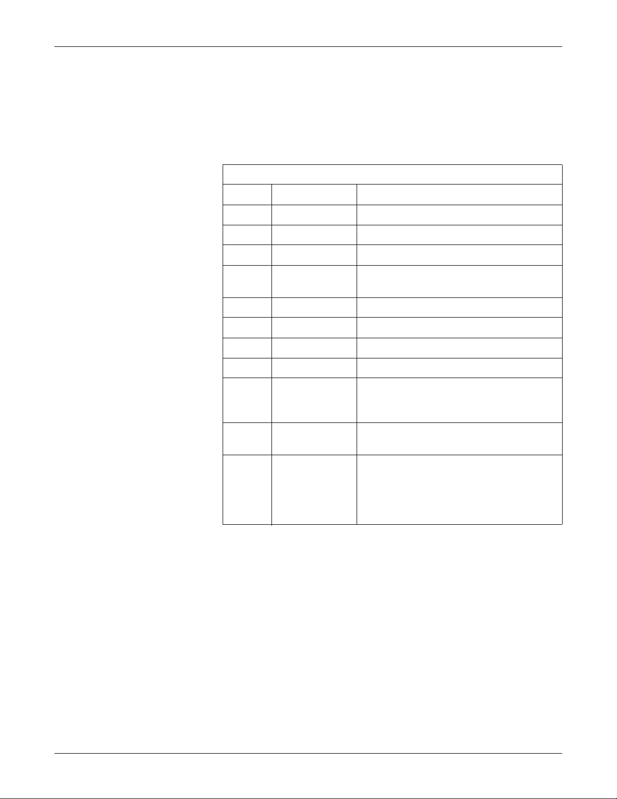
Revision Date Comment
Introduction: Manual Information
Table 1. Revision History, PN 2021337-036
A 1 August 2006 Initial release of document.
B 14 December 2006 Added FRUs for MobileLink Silex serial server.
C 1 February 2007 Edited EMC section for IEC 60601-2-51 compliance.
D 10 October 2008 Added -007 board, 009C SD Card and -002 Comm
PC board. Included Functional Checkout Procedure.
E 08 January 2010 Added PN 2022328-002 PCB MAC 3500 CAMV2.
F 10 May 2010 Revised security on electronic file.
Manual Purpose
G 12 December 2010 Revised to add service disclaimer addendum.
H 14 August 2012 Added 2022332-003 to Parts List.
J 19 June 2013 Updated for the new CPU (801212-008),
communcations board (2022332-004) , and display
assembly (2026799-002).
K 21 February 2014 Updated several part numbers with new ROHS-
compliant versions.
L 15 February 2019
This manual supplies technical information for service representative and technical
personnel so they can maintain the equipment to the assembly level. Use it as a
guide for maintenance and electrical repairs considered field repairable. Where
necessary the manual identifies additional sources of relevant information and or
technical assistance.
• Updated to remove CE markup.
• Updated to remove Authorized European
representative.
• Added the Instructions for Use.
• Updated UL symbol.
See the operator’s manual for the instructions
safely in accordance with its function and intended use.
necessary to operate the equipment
Intended Audience
This manual is intended for the person who uses, maintains, or troubleshoots this
equipment.
Revision L MAC™ 3500 Resting ECG Analysis System 1-3
2021337-036
Page 12

Introduction: Warnings, Cautions, and Notes
Related Documentation
The following documents are referenced in this manual and provide additional
information that may be helpful in the installation, configuration, maintenance, and
use of this product.
Part Number Title
2021337-035 MAC™ 3500 Resting ECG Analysis System Operator Manual
2036070-006 Marquette™ 12SL™ ECG Analysis Program Physician's Guide
2020299-021 MobileLink™ Wireless Communications Installation Manual
2025521-001 KISS™ Multilead Operator’s Manual
2020299-025 LAN Option for MAC™ Resting ECG Systems Installation and
roubleshooting Guide
T
2044854–112 Modular MAC™ ECG Trolley Service Manual
2056914–001 Modular MAC™ ECG Trolley Assembly I
2056914–002 Modular MAC™ ECG Trolley Assembly I
Warnings, Cautions, and Notes
The terms danger, warning, and caution are used throughout this manual to point out
hazards and to designate a degree or level or seriousness. Familiarize yourself with
their definitions and significance.
Hazard is defined as a source of potential injury to a
Term Definition
DANGER Indicates an imminent hazard which, if not avoid
serious injury.
WARNING Indicates a potential hazard or unsafe practice which, if not avoided, could
result in death o
CAUTION Indicates a potential hazard or unsafe practice which, if not avoided, could
result in minor personal injury or product/property damage.
NOTE Provides application tips or other useful information to a
the most from your equipment.
nstructions (US)
nstructions (Non-US)
person.
ed, will result in death or
r serious injury.
ssure that you get
1-4 MAC™ 3500 Resting ECG Analysis System Revision L
2021337-036
Page 13

Safety Messages
Introduction: Safety Messages
Additional safety messages may be found throughout this manual that provide
appropriate safe operation information.
DANGER
Do not use in the presence of flammable anesthetics.
WARNINGS
This is Class 1 equipment. The mains plug must be connected to
an appropriate power supply.
Operate the unit from its battery if the integrity of the protective
earth conductor is in doubt.
CAUTIONS
This equipment contains no serviceable parts. Refer servicing to
qualified service personnel.
U.S. Federal law restricts this device to the sale by or on the order
of a physician.
Responsibility of the Manufacturer
GE Medical Systems Information Technologies is responsible for the effects of
safety, reliability, and performance only if:
Assembly operations, extensions, readjustments, modifications, or repairs
are carried out by pers
The electrical installation of the relevant room complies with the
requirements
The equipment is used in accordance with the instructions for use.
ons authorized by us.
of the appropriate regulations.
Revision L MAC™ 3500 Resting ECG Analysis System 1-5
2021337-036
Page 14

General
Introduction: Safety Messages
The intended use of this device is to record ECG signals from surface ECG
electrodes. This device can analyze, record, and store electrocardiographic
information from adult and pediatric populations. This data can then be computer
analyzed with various algorithms such as interpretive ECG and signal averaging for
presentation to the user.
This device is intended for use under the direct supervision of
practitioner.
Failure on the part of the responsible individual, hospital, or institution using this
equipment to implement
equipment failure and possible health hazards.
To ensure patient safety, use only parts and accessories manufactured
recommended by GE Healthcare.
Contact GE Healthcare for i
equipment that are not recommended in this manual.
If the installation of this equipment, in t
the source must be a center-tapped, 240 V, single-phase circuit.
Parts and accessories used must meet the requireme
series safety standards, and/or the system configuration must meet the requirements
of the IEC 60601-1-1 medical electrical systems standard.
The use of ACCESSORY equipment not complying with the equivalent safety
requirements of this equipment may
system. Consideration relating to the choice shall include:
use of the accessory in the PATIENT VICINITY; and
evidence that the safety certification of the ACCESSORY has been
performed
60
601-1-1 harmonized national standard.
a satisfactory maintenance schedule may cause undue
nformation before connecting any devices to this
he USA, will use 240 V rather than 120 V,
nts of the applicable IEC 60601
lead to a reduced level of safety of the resulting
in accordance to the appropriate IEC 60601-1
a licensed health care
or
and/or IEC
1-6 MAC™ 3500 Resting ECG Analysis System Revision L
2021337-036
Page 15

Equipment Symbols
The following symbols may appear on the product or its packaging.
Introduction: Equipment Symbols
Type BF equipment. The acquisition module is protected from defibrillation
shoc
ks.
Alternating current.
Equipotential.
Charge the battery. The flashing amber LED next to this symbol indicate
you must connect the system to AC power to re-charge the battery
LAN port for connecting an Ethernet cable with a standard RJ-45 jack.
Internal modem port for connecting a phone line with a standard RJ-11 jack.
Do NOT throw the battery into the garbage.
Recycle the battery.
Consult accompanying documents.
This position of the switch removes battery power from the equipment.
Classified with respect to electric
specified hazards only in accordance with UL 60601-1, CAN/CSA C22.2
No. 601-1, CAN/CSA C22.2 No. 601-2-25, EN 60601-2-25, EN 60601-1-1,
IEC 60601-1-2: 2001.
shock, fire, mechanica
l, and other
s
.
To reduce the risk of electric shock, do
servicing to qualified personnel.
This symbol indicates that the waste of electrical and electronic eq
must not be dispo
separately. Please contact an authorized representative of the manufacturer
for information concerning the decommissioning of your equipment.
Revision L MAC™ 3500 Resting ECG Analysis System 1-7
2021337-036
sed as unsorted municipal waste and must be collected
NOT remove co
ver (or back). Refer
uipment
Page 16

Introduction: Equipment Symbols
This product consists of devices that may contain mercury, which must be
recycled or disposed of in accordance with local, state, or country laws.
(Within this system, the backlight lamps in the monitor display contain
mercury.)
Manufacturer name and address.
Consult instructions for use.
PCT. GOST marking symbolizing conformity with applicable Russian
Gosstandart tech
nical and safety standards.
1-8 MAC™ 3500 Resting ECG Analysis System Revision L
2021337-036
Page 17
Service Information
9A
SERIAL NUMBER
LABEL
SERIAL NUMBER
LABEL
Service Requirements
Refer equipment servicing to GE authorized service personnel only. Any
unauthorized attempt to repair equipment under warranty voids that warranty.
It is the user’s responsibility to report the need for service to GE or to one of their
authorized agents
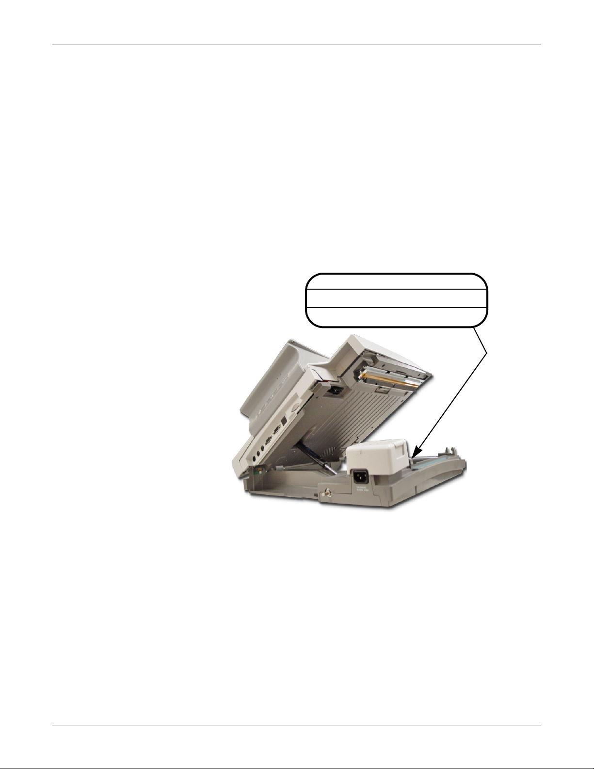
Equipment Identification
The serial number label is located inside the device as shown in the following
illustration.
Introduction: Service Information
.
Revision L MAC™ 3500 Resting ECG Analysis System 1-9
Every GE Healthcare device has a unique seria
number is formatted as shown in “Serial Number Format” o
NOTE
The examples shown are representative on
2021337-036
l number for identification. The serial
n page 1-10.
ly. Your product label may differ.
Page 18

Serial Number Format
### ## ## #### # #
ABCDEF
A
B
C
D
E
Introduction: Service Information
Table 2. Serial Number Format
1
A
Product code
B Year manufactured (00-99)
06 = 2006
07 = 2007
(and so on)
C Fiscal week manufactured
D Production sequence number
E Manufacturing site
F Miscellaneous characteristic
Label Format
1. The product code for the MAC 3500 described in this
manual is
A Date of manufacture in YYYY-MM format
B Part number of product
C Product code description
D Serial number (described above)
E Manufacturing site
SCA.
Table 3. Equipment Identification Label
1-10 MAC™ 3500 Resting ECG Analysis System Revision L
2021337-036
Page 19

2 Equipment Overview
Revision L MAC™ 3500 Resting ECG Analysis System 2-1
2021337-036
Page 20

For your notes
2-2 MAC™ 3500 Resting ECG Analysis System Revision L
2021337-036
Page 21

Equipment Overview: General Description
104A
CD
A
E
B
F
General Description
The MAC™ 3500 Resting ECG Analysis System is a 12-lead, 12-channel system
with a 6.5 inch (165 mm) diagonal display, active patient cable, and battery
operation. There are also options for communication capabilities.
Side View
Name Description
A keyboard Press the keyboard keys to control the system or to enter
data.
B display screen View the waveform and text data.
C modem port Connect the telephone cable here (optional feature)
D LAN port Connect to the LAN here (optional feature)
The green LED on the right side of this port indicates
a good ethernet link.
The amber LED on the left side of this port flashes to
indicate ne
E KISS pump
connector
F ECG signal input
connector
Connect the KISS pump here (optional feature).
Connect the patient cable here.
twork traffic.
Revision L MAC™ 3500 Resting ECG Analysis System 2-3
2021337-036
Page 22

Back View
105A
A BCD
Equipment Overview: General Description
Name Description
A back panel connectors Connect peripheral devices here.
B Secure Digital card slot Insert Secure Digital card for external storage here.
C ground lug Connect non-grounded peripheral devices to ensure
ipotential.
equ
D main AC power Insert the main AC power cable.
2-4 MAC™ 3500 Resting ECG Analysis System Revision L
2021337-036
Page 23

Equipment Overview: Connector Identification
106A
A BC D E F GH I
Connector Identification
WARNING
LEAKAGE CURRENT – Keep leakage current within acceptable
limits when connecting auxiliary equipment to this device.
Total system leakage must not exceed 300 microamperes (United
States) or 500 microamperes (international).
Table 4. Back Panel Connectors
Item Name Description
A A Connect an optional card reader o
B 1 External GE KISS pump connection.
C 2 Connect a local transmission cable, seria
bridge (wireless option).
D ANA/TTL Connect a device requiring analog data or TTL trigger
ltrasound, stress echo, ergometer, analog treadmill, blood
(u
pressure units, etc.).
E EXT.VID. Connect an external video display.
F IR Point at a MAC 5000, MAC 5500, MAC 3500, or MUSE
stem’s IR transceiver to transmit or receive ECG data.
sy
r optional bar code reader
l line, modem, or client
G card slot Insert the system card into this slot to archive or restore data
Revision L MAC™ 3500 Resting ECG Analysis System 2-5
2021337-036
from external media or
to update software.
Page 24

Equipment Overview: Connector Identification
Table 4. Back Panel Connectors (Continued)
H ground lug Connect non-grounded peripheral devices to ensure
equipotential.
I main AC power Insert the main AC power cable.
2-6 MAC™ 3500 Resting ECG Analysis System Revision L
2021337-036
Page 25

3 Installation
Revision L MAC™ 3500 Resting ECG Analysis System 3-1
2021337-036
Page 26

For your notes
3-2 MAC™ 3500 Resting ECG Analysis System Revision L
2021337-036
Page 27

Introduction
Installation: Introduction
This chapter describes how to assemble the MAC 5500 system and optional
accessories on the optional MAC Series Trolley, and it identifies the requirements
and configurations for using select devices with the ST option.
Revision L MAC™ 3500 Resting ECG Analysis System 3-3
2021337-036
Page 28

General Assembly
Installation: General Assembly
The following sections describes these tasks:
Adjusting the trolley height
Attaching the MAC device to the MAC Series trolley
Attaching the optional external modem
Attaching the magnetic card reader
Attaching the bar code reader
NOTE
These instructions describe the process only
for the MAC Series trolley (1). For
general assembly instructions for the modular MAC trolley (2), refer to the
Modular MAC Trolley Assembly Instructions identified in “Related
Documentation” on page 1-4.
3-4 MAC™ 3500 Resting ECG Analysis System Revision L
2021337-036
Page 29

Installation: General Assembly
MAC 3500
Patient Cable
Arm and Holder
Swivel
Casters
Trolley
Serial Number
105A
Front Cover
Locking
Casters
Use the following photograph of a complete assembly as a reference when attaching
the optional accessories.
NOTE
Because the optional trolley is made by another vendor for GE,
the serial
number format is different from that shown in “Serial Number Format” on
page 1-10.
Revision L MAC™ 3500 Resting ECG Analysis System 3-5
2021337-036
Page 30

Trolley Height Adjustment
107A
108A
The optional MAC 3500 Trolley can be assembled for one of two heights, 92.07 cm
(36.25 inches) or 84.45 cm (33.25 inches). The trolley is normally shipped at the
92.07 cm (36.25 inches) height but can be changed to fit your needs. To change to
the lower height, use the following steps:
1. Tip the trolley on its side and using a 1/2-inch socket, remove the 4 outer 1/
2-inch
Installation: General Assembly
bolts and slide the base assemble up on the column.
2. Remove the remaining bolts and mounting plate.
3. Flip the mounting plate and
reverse the procedure.
3-6 MAC™ 3500 Resting ECG Analysis System Revision L
2021337-036
Page 31

Installation: General Assembly
110A
109A
CAUTION
Do not over tighten. Over tightening the bolts may cause them to
strip.
Revision L MAC™ 3500 Resting ECG Analysis System 3-7
2021337-036
Page 32

Installation: General Assembly
111A
112A
4A
Installing the MAC™ 3500 Resting ECG Analysis System
To secure the MAC 3500 to the trolley assembly, follow these steps:
1. Lock the wheels to prevent the trolley from rolling.
2. Remove the end panel by pulling out and up.
3. Place the unit on the trolley surface, then slide
it on until the unit is firmly in
place and under the tab at the rear of the on the tray.
3-8 MAC™ 3500 Resting ECG Analysis System Revision L
2021337-036
Page 33

Installation: General Assembly
21A
MAC 3500
113A
114A
4. Secure the MAC 3500 to the trolley by tightening the three captive screws
located under the trolley tr
ay.
5. Replace the end panel by pushing up and in until you hear a snap.
6. Unlock the wheels to allow free m
ovement of the trolley.
Revision L MAC™ 3500 Resting ECG Analysis System 3-9
2021337-036
Page 34

Installation: General Assembly
115A, 116A
117A
118A
Installing the Optional External Modem Kit
NOTE
The internal modem is standard for the MAC 3500.
The modem and its mounting bracket comes as
sembled and ready to install on the
trolley. To install a modem kit on the trolley, complete the following steps:
1. Find the modem mounting site located under the patient
th
e trolley where the kit is to be installed.
2. Slide the assembly up in place so that the bracket s
cable arm at the rear of
lot catches on the bracket lip.
3. Tighten the three mounting screws to secure the modem to the trolley.
3-10 MAC™ 3500 Resting ECG Analysis System Revision L
2021337-036
Page 35

Installation: General Assembly
30A
4. Plug the modem cable into connector port 2 on the MAC 3500.
5. Refer to the operator’s manual for information on using the modem.
Revision L MAC™ 3500 Resting ECG Analysis System 3-11
2021337-036
Page 36

Installation: General Assembly
Card Reader
Assembly
Do Not Use
These Parts on
new style trolley
119A
112A
120A
Magnetic Card Reader Installation
The magnetic card reader and its mounting bracket are assembled and ready to
install on the trolley. Parts are included for two different trolley styles. Disregard
and do not use the parts indicated in the following illustration.
To install the magnetic card reader and its m
ounting bracket on the trolley, complete
the following steps:
1. Remove both end panels by pulling out and up at the bottom.
2. Using a Phillips screw driver, fasten the card
hand
le. Align with holes provided under front handle.
reader assembly under the front
3-12 MAC™ 3500 Resting ECG Analysis System Revision L
2021337-036
Page 37

Installation: General Assembly
Cable Routing
Rear View
34A
77A
70A
3. Route the cable around the trolley column towards the rear as shown below.
4. At the front, hold the cable to the side
th
e panel.
so it clears the front panel as you replace
5. Plug the cable connector into port A then
replace the back panel.
6. Refer to the MAC 3500 Operator’s Manual for information on using the
Magnetic Card
Revision L MAC™ 3500 Resting ECG Analysis System 3-13
Reader.
2021337-036
Page 38

Installation: General Assembly
Cable
Clamp
Cable
Clamp
Bracket
Barcode
Reader
71A, 72A
Cable
Clamp
Cable
Clamp
Bracket
73A
Barcode Reader Installation
The barcode reader and its mounting bracket are ready to install on the trolley. To
install the Bar Code Reader and its cable mounting bracket on the trolley, complete
the following steps:
1. Fasten the cable clamp bracket to the underside
Phill
ips screw driver and the self-tapping screws provided.
NOTE
DO NOT overtighten. Overtightening the s
strip and clamp to fail.
of the rear handle using a
crew may cause the screw to
3-14 MAC™ 3500 Resting ECG Analysis System Revision L
2021337-036
Page 39

Installation: General Assembly
Internal Access
Button
9A
Port A
Not enough cable slack.
Correct amount of cable slack.
2. Press the internal access button to open the MAC 3500, then plug the cable
conn
ector into port A. Opening the MAC 3500 before
allo
ws you to place the correct amount of slack to free the cable from stress
the MAC 3500 needs to be re-opened.
when
attaching the cable clamp
3. Next fasten the cable and clamp to the clamp
Observe that there is e
nough slack to allow free movement of the cable when re-
bracket, then close the MAC 3500.
opening the MAC 3500.
4. Refer to the MAC 3500 Operator’s Manual for information on how to use the
barcode reader.
Revision L MAC™ 3500 Resting ECG Analysis System 3-15
2021337-036
Page 40

For your notes
Installation: General Assembly
3-16 MAC™ 3500 Resting ECG Analysis System Revision L
2021337-036
Page 41

4 Troubleshooting
Revision L MAC™ 3500 Resting ECG Analysis System 4-1
2021337-036
Page 42

For your notes
4-2 MAC™ 3500 Resting ECG Analysis System Revision L
2021337-036
Page 43

Troubleshooting: Assembly Descriptions
Assembly Descriptions
The troubleshooting information in this chapter helps you narrow service problems
to one of the replaceable assemblies. These assemblies, illustrated in the following
diagrams, are discussed in more detail in the remainder of the chapter along with
replacement procedures.
PCB Block Diagram
The following diagram illustrates the logical relationship of the system components.
Revision L MAC™ 3500 Resting ECG Analysis System 4-3
2021337-036
Page 44

Troubleshooting: Assembly Descriptions
4-4 MAC™ 3500 Resting ECG Analysis System Revision L
2021337-036
Page 45

Connection Diagrams
Troubleshooting: Assembly Descriptions
The following diagram illustrates the physical I/O connections between the PCB and
external devices.
The following diagrams provide a detailed look
and the LVDS/LED display assembly.
Revision L MAC™ 3500 Resting ECG Analysis System 4-5
2021337-036
at the connection between the PCB
Page 46

Troubleshooting: Assembly Descriptions
LED/LVDS Display Assembly Diagram
The following illustration diagrams the connections for the LVDS/LED display
assembly (2026799-002), and the table that follows it identifies those connections.
Item GE Part Number Desciption
A1 2024701-001 ASSY DISPLAY CABLE MAC3500 (CMOS)
A2 2062075-001 LVDS/LED LCD PANEL
A4 2024701-001 MAC3500 PWR CABLE MAIN BOARD TO LVDS
A5 2061540-001 PWA MAC5500 LVDS DRV BRD ROHS
A6 2059277-001 ASSY MAC3500 BACKLIT CABLE-AUO
A7 2059322-001 MAC3500 LCD CABLE
4-6 MAC™ 3500 Resting ECG Analysis System Revision L
2021337-036
Page 47

Troubleshooting: General Fault Isolation
General Fault Isolation
Power-up Self-test
See the MAC 3500 Operator’s Manual, Chapter 2, “Equipment Overview: Getting
Started” to verify operation.
On power-up, the system automatical
good, the start up screen displays. If the equipment is not working properly, ask
yourself the following questions.
Is the unit turned on?
Have there been any changes in the use, location, or environment of the
equipment that
Has the equipment hardware or software been modified since last use?
Is operator error the cause of the problem? Try to repeat the scenario exactly
and com
ma
nual.
Is the battery installed?
When connected to the AC wall outlet, does the green AC power light glow?
Is the writer door closed?
could cause the failure?
pare that to the proper operation of the equipment described in th
ly runs an internal self-test. If all circuits test
e
Revision L MAC™ 3500 Resting ECG Analysis System 4-7
2021337-036
Page 48

Power-up Flow Chart
60B
Troubleshooting: General Fault Isolation
4-8 MAC™ 3500 Resting ECG Analysis System Revision L
2021337-036
Page 49

Poor Quality ECGs
Troubleshooting: General Fault Isolation
Poor quality ECGs can be caused by factors in the environment, inadequate patient
preparation, hardware failures related to the acquisition module, leadwires, cables,
or problems in the unit.
Use a simulator to obtain an ECG report.
external to the unit.
If the report is good, the problem is
Revision L MAC™ 3500 Resting ECG Analysis System 4-9
2021337-036
Page 50

Troubleshooting: General Fault Isolation
Visual Inspection
A thorough visual inspection of the equipment can save time. Small things—
disconnected cables, foreign debris on circuit boards, missing hardware, loose
components—can frequently cause symptoms and equipment failures that may
appear to be unrelated and difficult to track.
NOTE
Take the time to make all the recommended vi
detailed troubleshooting procedures.
Table 1. Visual Inspection List
Area Look for the following problems
I/O Connectors and Cables Fraying or other damage
Bent prongs or pins
Cracked housing
Loose screws in plugs
Fuses Type and rating. Replace as necessary.
sual checks before starting any
Interface Cables Excessive tension or wear
Loose connection
Strain reliefs out of place
Circuit Boards Moisture, dust, or debris (top and bottom)
Loose or missing components
Burn damage or smell of over-heated components
Socketed components not firmly seated
PCB not seated properly in edge connectors
Solder problems: cracks, splashes on board, incomplete feedthrough, prior modifications or repairs
Ground Wires/Wiring Loose wires or ground strap connections
Faulty wiring
Wires pinched or in vulnerable position
Mounting Hardware Loose or missing screws or other hardware, especially fasten
planes on PCBs
Power Source Faulty wiring, especially AC outlet
Circuit not dedicated to system
(Power source problems can cause static discharge, resetting problems, and
ers used as connections to ground
noise.)
4-10 MAC™ 3500 Resting ECG Analysis System Revision L
2021337-036
Page 51

Troubleshooting: Diagnostic Tests
13B
Diagnostic Tests
Verify that the MAC 3500 resting ECG analysis system operates properly by
running the diagnostic tests. These tests check the operation of the display screen,
speaker, keyboard, thermal writer, battery, and communication. Detailed
information displays on screen.
Loading the System Diagnostics Menu
1. Select Main Menu on the Resting screen.
2. Select System Setu
3. At the prompt type the word sy
th
e Enter key. If the password was not changed, the System Setup me
appears. If the men
NOTE
If the system’s unique password is ina
instructions in “Substitute Master Password” on page 4-26.
4. When the System Setu
F5).
5. Type pr
6. The System Dia
od at the service password prompt.
p.
stem, the password set at the factory, then press
u does not appear, use the master
ccessible, create one following the
p menu displays, hold down Shift and press F5 (Shift +
gnostics menu appears.
password.
nu
NOTE
The Fl
oppy Drive Tests option does not apply to the MAC 3500 system.
For information on Display Test, go to “Display Test” on page 4-12.
Revision L MAC™ 3500 Resting ECG Analysis System 4-11
2021337-036
Page 52

Display Test
14A
16A
Troubleshooting: Diagnostic Tests
For information on Speaker Test, go to “Speaker Test” on page 4-13.
For information on Keyboard Tests, go to “Keyboard Test” on page 4-13.
For information on Writer Tests, go to “Writer Test” on page 4-14.
For information on Battery Test, go to “Battery Test” on page 4-16.
For information on Communication Test, go to “Communication Test” on
page 4-18.
For information on Acq. Module Tests, go to “Acq. Module Tests” on page 4-
21.
For information on Analog I/O Tests, go to “Analog I/O Tests” on page 4-22.
For information on SD Card Tests, go to “SD Card Tests” on page 4-25.
The purpose of the test is to verify that all the screen pixels are working and that the
brightness and contrast samples are within the normal range.
Pixel Verification Test. Select the Pixel Verification Test and press F1 to see
whet
her any of the pixels are defective. Loss of pixels may require replacement
of the LCD display.
Gray Scale Test Patterns. This test is for manufacturing use only.
4-12 MAC™ 3500 Resting ECG Analysis System Revision L
2021337-036
Page 53

Speaker Test
15A
17A
The MAC
3500 keyboard
does not have
these keys.
See
NOTE
below.
Troubleshooting: Diagnostic Tests
The two available tone options are Loud and Soft. Select either of the tones and press
Enter. The tone level difference is minimal.
Keyboard Test
Select Ret
urn and press Enter to return to the System Diagnostics menu.
The Keyboard Test screen is shown below.
NOTE
Pressing the Leads key on
the MAC 3500 keyboard will display the word
Copy if the key is functioning properly.
To verify if all keys are functioning properly, press each key and verify that its
valu
e is highlighted on the screen and displayed at the top. The numeric
th
at is displayed at the top of the screen is the scan code representation of th
pressed key
screen aft
Check both the Shift keys by pressing each in combination with a letter to
dis
play a capital letter. For example pressing Shift + a will return a capital A.
Revision L MAC™ 3500 Resting ECG Analysis System 4-13
. It is normal for the background value for the key to remain on
er it is pressed so you know it has been checked. Check all keys.
2021337-036
value
e
the
Page 54

Trim Pad Control Test
37A
18A
Writer Test
Troubleshooting: Diagnostic Tests
Trim Pad Control
Use the following steps to verify operation of the trim pad control.
Press the center of the trim pad control and verify that the word IN is displayed
on the screen.
Press arrow keys to change the displayed arrow position. A beep sound is
generated with each arrow press.
Press Shift + F6 to exit the test.
The purpose of writer tests is to check the motor speed control, paper speed, paper
tracking, paper cueing, and print head quality.
During the tests, make the following general checks.
The first character printed should not be distorted.
The writer should not skew or crush either edge of the paper.
The large triangles and diagonal lines printed across the pages should be
strai
ght and uniform, without curves or wavering.
The perfs should align with the tear bar on the door after cueing.
The paper travel should be smooth.
The speed tests might indicate a mechanical problem. There is no adjustment
for the speed, but it
indicates that a pulley or gear is slipping.
C-Scan Test 1, C-Scan Test 2, C-Scan Test 3. These tests are for writer vendor
use onl
y.
4-14 MAC™ 3500 Resting ECG Analysis System Revision L
2021337-036
Page 55

Troubleshooting: Diagnostic Tests
50 mm/s Test Pattern I, 25 mm/s Test Pattern I, and 5 mm/s Test Pattern I. Test
patterns
check for the
The length of the printout from start to finish measures 250 mm ± 5 mm.
are used to check the paper speed control.
following:
Use the grids located
printout is outside of
hermal writer assembly. See “Writer Roller/Carriage Asse
t
on the top and bottom of the page for reference. If
range, paper speed is too fast or too slow
Run each test pattern and
the
. Replace
mbly
Replacement” on page 5-33.
Check that the long diagonal lines across the test pattern are straight. If
lines
are wavy or curved, the paper speed is not constant or the roller is ou
of round, replace
thermal writer assembly. See
“Writer Roller/Carriage
Assembly Replacement” on page 5-33.
Check that the test pattern printing is consistent. A white or black line
acros
s the pattern indicates a defective or missing print head dot
. See
“Printhead Assembly Replacement” on page 5-18.
Roller Test. During the check, perform the following general checks:
After cueing, printing should start at approximately 13-14 mm on the page.
The pattern will appear as diagonal light and dark wavy bands.
Isolated light spots indicate a flat spot on the roller.
A white line across the length of the page indicates a missing print head
do
t.
Dark lines across the width of the page indicate gear tolerance problems.
Lines too close together at the start of the test indicate an incorrect start-up
speed.
NOTE
Uneven darkness can appear if AC power is on during this test.
t
Test Pattern II. This test is not needed. It is a combination of Test Pattern I and
Roller Tests.
and variou
Test Pattern II Continuous. This test is not needed. Test Pattern II runs
cont
inuously until stop is pressed.
Continuously Run Out Paper. This test is for manufacturing use only. It tests
how
well the unit self-corrects tracking problems.
The first three pages consist of a series of triangular waveform
s hashmarks. The fourth page is a partial Roller Test.
s
Revision L MAC™ 3500 Resting ECG Analysis System 4-15
2021337-036
Page 56

Battery Test
19A
20A
Troubleshooting: Diagnostic Tests
Battery tests check the current battery status, battery discharge rate and battery
charge rate. Test results are stored in memory and can be printed out. The graphic
displayed shows the Battery Test menu. Each test is covered in detail below.
Battery Status. This test displays and constantly updates current information on
the battery voltage, battery current, percent of charge remaining and
battery
temperature.
Battery Voltage. With a reading of 80% or more for the percent of charge
rem
aining, the battery voltage should be between 15 and 24 vo
voltage is below 15 volts,
Battery Current. Disconnect AC power. If the battery current is less than -
0.7 amps, the main CPU may need to be replaced. For
-0.8 amps, consider
the battery may need to be replaced.
example if current is
replacing CPU. See “Main CPU Board Replac
lts. If battery
ement”
on page 5-22.
Battery Temperature. A temperature reading over 45° C indicates a failure.
If battery tem
consider replacing
Ambient Temperature. Indicates the temperature inside the unit. The
tempera
perature is more than
battery.
ture displayed is accurate to within
10° C over the ambient temperature
+5°C in the range of 0°C to
50°C. Ambient temperatures not within this range cannot be displayed.
4-16 MAC™ 3500 Resting ECG Analysis System Revision L
2021337-036
Page 57

Troubleshooting: Diagnostic Tests
21A
Battery Discharge Test. This test monitors a full discharge cycle. This test will
take
several hours to run.
To run test:
Select Battery Dischar
to fully charge. Remove AC power when prompted. Select OK
Batter
y Discharge Test. Allow battery to fully discharge. Unit will
automatically shut
To view test results:
Connect MAC 3500 to AC power; return to the Battery T
ge Test; plug unit into AC power and allow battery
and reselect
off.
est menu and
select Print Battery Discharge Test. Test results remain in memory until th
Batter
y Discharge Test is run again.
e
Battery Discharge Test wind
ow
NOTE
Consider replacing the battery if discharge capacity is less than 2000 (2k)
mAH.
Battery Charge Test. This test completely discharges the battery and monitors a
char
ge cycle. This test can take up to six hours to run. Select Print Batter
Ch
arge Test to view test results.
y
NOTE
The Battery Dischar
ge Test takes less time to run and is a better indicator of
battery condition.
To run test:
Select Ba
d
ischarge; when prompted, plug unit into AC power and select OK
batt
To view test results:
Return to the Battery T
results remain in memory until the Battery Charge Test is
ttery Charge Test; unplug unit and allow battery to completely
. Allow
ery to fully charge until test is complete.
est menu and select Print Battery Charge Tes t. Test
run again.
Revision L MAC™ 3500 Resting ECG Analysis System 4-17
2021337-036
Page 58

Communication Test
22A
Troubleshooting: Diagnostic Tests
Communication tests are available for the COM ports, external modem, internal
modem and Ethernet. The Communication Test menu is shown below:
COM Port Loopback Test. The Communications (COM) Port Loopback test
sends vari
expects
the same character to return to its receiving lines. Perform test
COM 1 and
0.
350
ous ASCII characters out from the COM Port’s transmit lines
COM 2 ports. COM 3 and COM 4 are not included on the MA
and
for both
To run test, connect pin 3 to pin 5 using a jumper and then press any key to st
The test will
return a pass/fail for several baud rates.
C
art.
4-18 MAC™ 3500 Resting ECG Analysis System Revision L
2021337-036
Page 59

Troubleshooting: Diagnostic Tests
24A
Com Port Loopback Test Results Window
NOTE
To repair a defective COM port, replace
Board Replacement” on
External Modem Test. Connect a modem to the COM 2 port and select the
External
m
Modem Test. The test communicates with the modem and
odem ID number, firmware rev, and current parameter settings, if any.
communication with the modem
splay N/A.
di
page 5-22.)
is unsuccessful, the ID
the CPU board. (See “Main CPU
returns the
If
and firmware rev will
NOTE
Although COM 2 is also used to connect the wireless client bridge, this test
is design
ed to check a modem only. It cannot be used to test the wireless
client bridge.
Revision L MAC™ 3500 Resting ECG Analysis System 4-19
2021337-036
Page 60

Troubleshooting: Diagnostic Tests
25A
26A
Internal Modem Test. Select the Internal Modem Test. The test returns the
m
odem ID number, firmware rev, and current parameter setti
communication with the modem
splay N/A.
di
is unsuccessful, the ID
ngs. If
and firmware rev
NOTE
If the test fails, consider rep
Ethernet Module Test. Select the Ethernet Module Test. The test returns IP
lacing the communication board.
address, subnet mask, and MAC Address settings for the Ethernet modul
commu
ma
nication with the Ethernet module is unsuccessful, the IP addr
sk, and MAC address will display N/A.
ess, subnet
e. If
NOTE
If the test fails, consider replacing the communication board. See “COMM
Board Replacement” on
page 5-30 for more information.
If the LAN connection on the communication board returns information
bu
t network communication problems still exist, use the LED status
dicators on the LAN connection to see if the connection to the network is
in
active. You can also use a ping command from the MUSE server to see if
the MUSE system can find the unit on the network.
4-20 MAC™ 3500 Resting ECG Analysis System Revision L
2021337-036
Page 61

Acq. Module Tests
Tests if the acquisition
board is communicating.
Displays the acquisition board noise floor
Displays the software
version of the acquisition
board
27A
Troubleshooting: Diagnostic Tests
To check the internal acquisition board, connect all leads to the RL lead on the
patient cable and keep them separated and away from any external power source.
NOTE
One way of doing this is to connect all leads to a patient simulator and leave
simulator turned off.
the
NOTE
The Bu
tton Pressed test does not apply to the MAC 3500 system.
Revision L MAC™ 3500 Resting ECG Analysis System 4-21
2021337-036
Page 62

Analog I/O Tests
28A
20A
Troubleshooting: Diagnostic Tests
The Analog I/O Tests option checks the ANA/TTL connection and consists of four
different tests.
Analog Output Test. The Analog Output Test. This test involves monitoring of
analo
g outputs using an oscilloscope.
Follow the on-screen prompts to run the Anal
Analog Input Test. This test involves connecting a DC voltage to the DC input
pi
ns of the ANA/TTL connector. The voltage of the DC input is displayed.
Follow the on-screen prompts to run the Anal
og Output Test.
og Input Test.
4-22 MAC™ 3500 Resting ECG Analysis System Revision L
2021337-036
Page 63

Troubleshooting: Diagnostic Tests
31A
PIN Name Pin Name
1 +12v 6 DC Output 2
2 DC Output 1 7 DC Input 1
3
*
TTL Trigger Output
* also called “QRS Trigger”
8
ECG Output
4 Ground 9 DC Input 2
5 Ground
1
6
5
9
33A
DCOut Loopback Test. This involves connecting the DC Outputs to the DC
In
puts. The test sends all possible values out the DC Outputs and confirms th
correct values
are read from the DC Inputs. A pass/fail result is displa
yed at the
end of the test.
To run the test, connect DCOut1 (pin2) to Analog Input (pin 7) and DCOut2
(p
in 6) to Analog Input (pin 9).
at
NOTE
If test fails you may need to replace
the CPU board.
(See “Main CPU Board Replacement” on page 5-22.)
ECGOut/QRSTrigger Loopback Test. This involves connecting the ECG Output
and
TTL Trigger Output to the DC Inputs. The test sends all possible values ou
the
ECG Output and a square wave out the TTL Trigger Output. It confirms
correct values
end of the test. If
are read from the DC Inputs. A pass/fail result is displa
test fails you may need to replace the CPU board. (See
yed at the
CPU Board Replacement” on page 5-22.)
Revision L MAC™ 3500 Resting ECG Analysis System 4-23
2021337-036
t
that
“Main
Page 64

Troubleshooting: Diagnostic Tests
PIN Name Pin Name
1 +12v 6 DC Output 2
2 DC Output 1 7 DC Input 1
3
*
TTL Trigger Output
* also called “QRS Trigger”
8
ECG Output
4 Ground 9 DC Input 2
5Ground
1
6
5
9
To run test, connect ECGOut1 (pin 8) to Analog Input (pin 7) and QRSTrigger
(pin 3) to Analog Input (pin 9).
NOTE
If test fails you may need to replace
Board Replacement” on
page 5-22.)
the CPU board. (See “Main CPU
Floppy Drive Tests
This option does not apply to the MAC 3500 system.
4-24 MAC™ 3500 Resting ECG Analysis System Revision L
2021337-036
Page 65

Internal Memory Tests
35A
36A
Troubleshooting: Diagnostic Tests
The Internal Memory Test checks for bad blocks and amount of free memory. After
the test is completed you are given the option of reformatting the internal memory.
CAUTION
Reformatting will erase all data in memory, including patient data.
Reformatting will not affect the system software or the System
Setups.
SD Card Tests
Follow on-screen prompts to perform the Internal Memory Tests.
The SD Card Tests option performs a read/write test on the SD card currently
installed. Responds with a PASS or FAIL.
Follow on-screen prompts to perform the SD Card Tests.
If card is not formatted correctly, an error mes
sage will appear at the bottom of the
screen.
NOTE
To format a card, insert the SD card and copy data to the card using the Co
command from File Manager. The MAC 3500 software will then prompt you to
rmat the card. Follow on-screen prompts. Refer to the MAC 3500 Operator’s
fo
Manual for details.
py All
Revision L MAC™ 3500 Resting ECG Analysis System 4-25
2021337-036
Page 66

Substitute Master Password
Troubleshooting: Diagnostic Tests
If you do not have access to the system’s password, you can create a master
password as follows.
1. At the prompt for the system password, enter meimac. A random 6-digi
num
ber displays on the screen. (For example, 876743.)
t
2. Write the number down and create a new 6-digit number by adding alternatin
di
gits from the random number as follows. Add:
first and third digits,
second and fourth digits,
third and fifth digits,
fourth and sixth digits,
fifth and first digits, and
sixth and second digits.
Disregard the 10’s column when adding the digits. The new number from the
exam
ple above would be 440020.
3. Enter the new number, then press the Enter key
di
splays. This process only works once, so you should reprogram the password
. The System Setup menu
permanently.
4. Go to the Ba
sic System menu.
5. Select Miscellaneous Setup.
6. Select the System pass
7. Press the En
ter key.
word line and type the new password in the space.
g
8. Select Save Setu
9. Select To system.
p from the System Setup menu.
4-26 MAC™ 3500 Resting ECG Analysis System Revision L
2021337-036
Page 67

Troubleshooting: Equipment Problems
Equipment Problems
ECG Data Noise
If the acquired ECG data displays unacceptable noise levels:
When troubleshooting noise or signal quality, be sure the problem is not being
caused by poor skin
Careful sk
in
Advisor. Hookup Advisor can be turned on or off in the ECG me
Se
Check for defective or date expired electrodes.
Check for defective, broken, or disconnected leadwires.
Run the Acquisition Module Tests in the Diagnostic menu and make sure all
lead wires pass
preparation, or placement and condition of
in preparation is the key to an interference-free ECG.
dicated using Hookup advisor. Click here to learn more about Hook-up
lect System Setup ECG EC
the noise test.
G Acquisition.
electrodes.
Signal quality is
nu.
Revision L MAC™ 3500 Resting ECG Analysis System 4-27
2021337-036
Page 68

System Errors
i
Troubleshooting: System Errors
The following errors may occur while you are operating this system. You may be
required to perform some action.
If you perform the recommended actions an
authorized service personnel. See “How to Reach Us” to find out how to contact GE.
Problem Cause Solution
appears on the screen.
flashes intermittently.
appears on the screen.
The system does not power up when
operating from battery power.
The system shuts down when operating
from batte
“X” Lead disconnected message appears. Electrode(s) disconnected. Reconnect the electrode(s).
MODEM ERROR. The remote device is
not responding. Would you
Cannot use the system because D
Password does not work.
ry power.
like to retry?
evice
No battery is installed in the system.
The battery charge is low.
The writer door is open.
The battery is empty.
Battery is empty, or the Automatic Shutdown
feature is enabled.
Modem not connected. (If wireless option,
client bridge not connected.)
(Wireless option only) MAC 3500 is not
hin range of access point.
wit
Device Password has been changed or has
not been adequately communicated to the
staff.
d the condition still remains, contact
Install a battery and connect the system to
an AC wall
Connect the system to an AC wall outlet to
charge the battery.
Close the writer door.
Connect the system to an AC wall outlet to
charge the battery.
Connect the system to an AC wall outlet to
charge the battery, or power on the system.
Connect and retry.
Relocate MAC 3500 to within range of
access point and retry transmission.
Override the Device Password prompt by
pressing the following keys at the same time:
outlet to charge the battery.
63A, 64A, 65A
NOTE
For information about troubleshooting the MobileLink Standard Security
ion, see “MobileLink Installation & Troubleshooting Guide” (PN 2002783-
opt
060).
For information about troubleshooting the MobileLink Ultra High Security
ion, see “MobileLink UHS Installation & Troubleshooting Guide” (PN
opt
2020300-051).
4-28 MAC™ 3500 Resting ECG Analysis System Revision L
2021337-036
Page 69

Troubleshooting: Frequently Asked Questions
Frequently Asked Questions
Maintenance
NOTE
See Operator’s Manual for complete System Set
Save Setups
Q: How do I save changes I have made to the System Setups?
A: Check the following:
Return to Menu by pressing the esc key or selecting More from the menu
until you see System Setup.
Select System Setup.
Select Save Setup.
Select To S y s t e m .
You can select Main Menu to exit System Setup.
Storing ECGs
up information.
Format an SD Card
Cleaning
Q: Why won't any of the ECGs I perform save to the SD card?
A: Check the following:
Check that the SD card is fully inserted into the drive.
Make sure you are using 64 MB SD cards.
Verify that the SD card is not write-protected.
Try a new SD card.
If your system is not set up to automatically save records, you must
manually save by pressing Store.
Q: How do I format an SD card in the MAC 3500?
A: Most secure digital cards do not require formatting.
SD card is used with the system, the following message will display:
This SD Card cannot be read and requires formatting. Formatting will
destroy al
Select Ye
l data on this SD Card. Are you sure you want to format?
s to format the SD card.
In the event an unformatted
Q: Should I clean the MAC 3500?
A: Clean the exterior surfaces of all the equipment and peripheral devices monthly,
or m
ore frequently if needed.
Use a clean, soft cloth and a mild dishwashing detergent diluted in water.
Wring the excess water from the cloth. Do NOT drip water or any liquid on
the writer assembly, and avoid contact with open vents, plugs, an
conn
ectors.
Revision L MAC™ 3500 Resting ECG Analysis System 4-29
2021337-036
d
Page 70

Battery Capacity
Troubleshooting: Frequently Asked Questions
Dry the surfaces with a clean cloth or paper towel.
Q: What is the capacity of the battery?
System Setup
Location Number
A: We recommend that the MAC 3
500 be plugged into a wall outlet whenever it is
not in use. However, the life of the battery is approximately 100 ECGs and onepage reports or six hours of continuous operation (without printing).
Q: When entering in the patient data, how do I get the Location field to
automatically populate with the same number?
A: The Location nu
mber can be set in System Setup to save you from entering it for
each test.
Go to System Setup.
Select Basic System.
Select Miscellaneous Setup.
Arrow down to Location and type in the number you want set as your
default
. Then press Enter.
Press the esc key until you return to System Setup.
Select Save Setup.
Select To S y s t e m .
You can select Main Menu to exit System Setup.
Patient Questions
Q: How do I change what questions I see when I am entering the patient data?
A: The patient questions you see on the Pati
were set up in System Setup.
Go to System Setup.
Select Basic System.
Select Patient Questions.
Select the patient questions you want to include when entering the patient
data for a test.
Press the esc key until you return to System Setup.
Select Save Setup.
Select To S y s t e m .
You can select Main Menu to exit System Setup.
4-30 MAC™ 3500 Resting ECG Analysis System Revision L
2021337-036
ent Data window when starting a test
Page 71

Passwords
Troubleshooting: Frequently Asked Questions
Q: Can you set up a password for the Delete function that is different than the
System Setup password?
Clinical
Report Format
A: No. The password for the S
ystem Setup and the Delete function are the same.
Q: How do I change the way an ECG looks when it prints out?
A: Do the following steps.
Go to System Setup.
Select ECG.
Select which type of ECG report you want to change:
Select unconfirmed reports from the menu.
Find the report type you want the MAC 3500 to print.
Place the number of copies you want in the appropriate column.
If you want the MAC 3500 or 12SL interpretation included on the ECG, put the
num
ber of copies you want in the “with” column.
If you do not want the MAC 3500 interpretation to print on the ECG, put the
num
ber of copies you want in the “without” column.
Click view report type, to see the examples of the report formats.
Press the esc key until you return to System Setup.
Select Save Setup.
Select To Sy s te m .
You can select Main Menu to exit System Setup.
Editing
Q: Can you edit the interpretation at the MAC 3500, and then transmit the edited
record to the MUSE system as an unconfirmed record?
A: If you edit demographic information only the record is still transmitted to the
MUSE
system as an unconfirmed record. However, if you edit the
interpretation, the data will not be saved unless the record is confirmed at the
MAC 3500. The record is transmitted to the MUSE system as a confirmed
record as well.
Revision L MAC™ 3500 Resting ECG Analysis System 4-31
2021337-036
Page 72

Entering Patient Data
Troubleshooting: Frequently Asked Questions
Q: Do I have to enter all the Information I see on the Patient Data screen?
A: In S
patient identification number, or medical record number) be entered. It is not a
requirement to enter any other data. However, we recommend that you enter the
patient name and identification number, at the least. If you are transmitting to
the MUSE system you will want to enter the Location number as well. If an
emergency situation dictates that you must complete the test. without entering
the patient data, make sure you edit the record to add the missing information
before you transmit it to the MUSE system.
Transmission
Losing Fields When Transmitting
Q: Why do I lose the Referring MD and Technician names off of my reports when
I transmit records to the MUSE system?
A: Your MAC 3500 may be transmitting to the SDLC modem on the MUSE
system instead of the CSI
transmitting to the MUSE system CSI phone number.
ystem Setup Basic System Patient Questions you can require that the
modem. Check in System Setup to make sure you are
4-32 MAC™ 3500 Resting ECG Analysis System Revision L
2021337-036
Page 73

Troubleshooting: Input and Output Connectors
2
1
6
5
3
4
66A
6
3
1
8
5
4
2
7
67A
Input and Output Connectors
The following pages detail the input/output signals for those connectors. The pin-bypin descriptions identify the signal names and pin outs for each connector on the
unit.
A Pins (J1)
Pin Name
1 Data
2 NC
3 Ground
4 +5V
5 Clock
Table 2. A Pins (J1)
COM1 (COM3/4) Pins (J3)
Pin COM1 Signal COM3/4 Signal
1 RTS COM3 TxD
2 CTS COM3 RxD
3 TxD
4 Ground
5 RxD
6 DTR COM4 TxD
7 +12V
8 DSR COM4 RxD
6
NC
Table 3. COM1 (COM3/4) Pins (J3)
Revision L MAC™ 3500 Resting ECG Analysis System 4-33
2021337-036
Page 74

COM2 Pins (J5)
6
3
1
8
5
4
2
7
67A
6
9
5
1
68A
Analog Pins (J6)
Troubleshooting: Input and Output Connectors
Table 4. COM2 Pins (J5)
Pin Name
1 RTS
2 CTS
3 TxD
4 Ground
5 RxD
6 DTR
7 +12V
8 DSR
Table 5. Acquisition Module Connector (J6)
Pin Name
1 +12V
2 DC Output 1
3 TTL Trigger Output
4 Ground
5 Ground
6 DC Output 2
7 DC Input 1
8 ECG Output
9 DC Input 2
4-34 MAC™ 3500 Resting ECG Analysis System Revision L
2021337-036
Page 75

EXT. VID. Pins (J7)
1
6
15
5
11
10
68A
Troubleshooting: Input and Output Connectors
Table 6. External VGA Video (J7)
Pin Name
1 Red Video
2 Green Video
3 Blue Video
4 Ground
5 Ground
6 Ground
7 Ground
8 Ground
9 NC
10 Ground
11 Ground
12 NC
13 Horizontal Sync
14 Vertical Sync
15 NC
Revision L MAC™ 3500 Resting ECG Analysis System 4-35
2021337-036
Page 76

Troubleshooting: CPU PCB Input/Output Signals
CPU PCB Input/Output Signals
Pin No. Signal
1 18V Battery Power
2 18V Battery Power
3 Battery Temperature Sense
4 3V Temperature Sense Power
5 Battery Ground
6 Battery Ground
Pin No. Signal
1 12V Power
Battery Pack/Monitor, J2
LCD Backlight, J4
2 12V Power
3 12V Power
4 Ground
5 Ground
6 Brightness Select
7 Backlight Enable
8 NC
9 Ground
10 Ground
Keyboard, J8
Pin No. Signal
1 NC
2 NC
3 NC
4 NC
5 NC
6 Sense4
7 Sense2
8 Sense1
9 Sense0
4-36 MAC™ 3500 Resting ECG Analysis System Revision L
2021337-036
Page 77

Troubleshooting: CPU PCB Input/Output Signals
Keyboard, J8 (Continued)
10 Sense3
11 Sense5
12 Sense6
13 Sense7
14 Drive0
15 Drive1
16 Drive2
17 Drive3
18 Drive4
19 Ground
20 Power Key
21 Drive5
22 Drive6
23 Drive7
24 Drive8
25 Drive9
26 Drive10
LCD, J10
Pin No. Signal
1 Ground
2 Pixel Clock
3 Hsync
4 Vsync
5 Ground
6 R0 (LSB)
7 R1
8 R2
9 R3
10 R4
11 R5 (MSB)
12 Ground
13 G0 (LSB)
14 G1
15 G2
16 G3
Revision L MAC™ 3500 Resting ECG Analysis System 4-37
2021337-036
Page 78

Troubleshooting: CPU PCB Input/Output Signals
LCD, J10 (Continued)
17 G4
18 G5 (MSB)
19 Ground
20 B0 (LSB)
21 B1
22 B2
23 B3
24 B4
25 B5 (MSB)
26 Ground
27 Data Enable
28 3V Power
29 3V Power
30 NC
31 NC
Power Supply/Motor, J11
Pin No. Signal
1 Motor Encoder B
2 5V Power
3 Motor A
4 Motor Encoder A
5 Ground
6 Motor B
7 NC
8 28V Power
9 Ground
10 Battery Charge LED
11 28V Power
12 Ground
13 Door Open Detect
14 Ground
4-38 MAC™ 3500 Resting ECG Analysis System Revision L
2021337-036
Page 79

Troubleshooting: CPU PCB Input/Output Signals
Thermal Printer, J12
Pin No. Signal
1 Thermal Printer Power
2 Thermal Printer Power
3 Thermal Printer Power
4 Thermal Printer Power
5 Thermal Printer Power
6 Thermal Printer Power
7 Thermal Printer Power
8 Ground
9 Ground
10 Ground
11 Ground
12 Ground
13 Ground
14 Ground
15 Cue Sense
16 NC
17 5V Main Power
18 Ground
19 Data Strobe
20 Data Strobe
21 Data Strobe
22 Data Strobe
23 Data Load
24 Data Clock
25 Print Head Temperature
26 Pixel Data
Revision L MAC™ 3500 Resting ECG Analysis System 4-39
2021337-036
Page 80

Troubleshooting: CPU PCB Input/Output Signals
Floppy Disk Drive, J13
(for floppy drive — not installed
Pin No. Signal
1 5V Power
2 Index
3 5V Power
4 Drive Select 0
5 5V Power
6 Disk Change
7 NC
8 Media Sense 0
9 Media Sense 1
10 Motor Select 0
11 NC
12 Direction
13 NC
14 Step
15 Ground
16 Write Data
17 Ground
18 Write Gate
19 Ground
20 Track 0
21 Ground
22 Write Protect
23 Ground
24 Read Data
25 Ground
26 Head Select
4-40 MAC™ 3500 Resting ECG Analysis System Revision L
2021337-036
Page 81

Troubleshooting: CPU PCB Input/Output Signals
Acquisition Module, J14
Pin No. Signal
1 Power
2 Ground
3 TX+ (RS485)
4 TX- (RS485)
5 RX+ (RS485)
6 RX- (RS485)
7 NC
8 NC
9 NC
10 NC
KISS Pump, J19
Pin No. Signal
1 KISS Pump Power (12V DC)
2 NC
3 GND
4 GND
Acquisition Module, J20
Pin No. Signal
1 TX- (RS485)
2 TX+ (RS485)
3 RX- (RS485)
4 RX+ (RS485)
5 GND
6 Power 12V
7 NC
8 NC
9 NC
10 NC
Revision L MAC™ 3500 Resting ECG Analysis System 4-41
2021337-036
Page 82

Troubleshooting: CPU PCB Input/Output Signals
LCD Backlight, J23
Pin No. Signal
1 GND
2 GND
3 Power 5V DC
4 Power 5V DC
5 Relay Port 1 (Resistance)
6 Relay Port 2 (Resistance)
4-42 MAC™ 3500 Resting ECG Analysis System Revision L
2021337-036
Page 83

5 Maintenance
Revision L MAC™ 3500 Resting ECG Analysis System 5-1
2021337-036
Page 84

For your notes
5-2 MAC™ 3500 Resting ECG Analysis System Revision L
2021337-036
Page 85

Maintenance: Introduction
Introduction
Recommended Maintenance
Regular maintenance, irrespective of usage, is essential to ensure that the equipment
will always be functional when required.
WARNING
Failure on the part of all responsible individuals, hospitals or
institutions, employing the use of this device, to implement the
recommended maintenance schedule may cause equipment failure
and possible health hazards. The manufacturer does not in any
manner, assume the responsibility for performing the
recommended maintenance schedule, unless an Equipment
Maintenance Agreement exists. The sole responsibility rests with
the individuals, hospitals, or institutions utilizing the device.
Required Tools and Supplies
In addition to a standard set of hand tools, you will need the items listed in the table
below.
#10 Torx driver
#6 Torx driver
Phillips screw driver
Leakage current tester MT-1216-02AAMI (for 220V)
Multifunction micro-simulator MARQ 1
Precision dust remover
Lint-free soft cloth TX609
PS2 style keyboard (Japan only)
Table 1. Tools and Supplies
Item Part Number
MT-1216-01AAMI (for 110V)
Revision L MAC™ 3500 Resting ECG Analysis System 5-3
2021337-036
Page 86

Maintenance: Inspection and Cleaning
Inspection and Cleaning
Visual Inspection
Perform a visual inspection of all equipment and peripheral devices daily. Turn off
the unit and remove power before making an inspection or cleaning the unit.
Check the case and display screen for cracks or other damage.
Regularly inspect all cords and cables for fraying or other damage.
Verify that all cords and connectors are securely seated.
Inspect keys and controls for proper operation and check that toggle keys do not
stick in one
Chap
ter 5 of this manual.
Exterior Cleaning
Clean the exterior surfaces monthly, or more frequently if needed.
position. If necessary, perform the
keyboard test described in the
Interior Cleaning
General
Thermal Printhead Cleaning
1. Use a clean, soft cloth and a
2. Wring the excess water from the cloth. Do not drip water or any liquid on the
equi
pment, and avoid contact with open vents, plugs, or connectors.
3. Dry the surfaces with a clean cloth or paper towel.
Check for dust buildup on the surfaces of the interior circuit boards, components,
and power supply. Use commercially available compressed air to blow away the
accumulated dust. Follow the manufacturers directions.
Clean the thermal printhead every three months or more often with heavy use. A
build-up of thermal paper coating on the printhead can cause light or uneven
printing.
Use a solution containing alcohol on a nonwoven, nonabras
Cloth to wipe off the printhead. Do not use paper toweling, as it can scratch the
printhead.
mild dish washing detergent diluted in water.
ive cloth such as Techni-
5-4 MAC™ 3500 Resting ECG Analysis System Revision L
2021337-036
Page 87

Maintenance: Checking Electrical Safety
Thermal
Printhead
1A
Checking Electrical Safety
The device should be checked annually for current leakage and ground continuity.
For details, see “Electrical Safety Checks” on pag
e 5-38.
Revision L MAC™ 3500 Resting ECG Analysis System 5-5
2021337-036
Page 88

Maintenance: FRU Replacement Procedures
writer button
12A
FRU Replacement Procedures
Disassembly Guidelines
Prior to performing any disassembly procedures, perform the following:
If possible, process any ECGs remaining in storage.
If possible, print out set-up for future reference.
Disconnect the unit from the AC wall outlet and remove the power cord from
th
e unit.
Remove the battery as described in “Battery Replacement”.
If the MAC 3500 system is mounted to the trolley, remove it from the trolley as
descri
bed in “Remove MAC 3500 System From Trolley”.
Remove the writer paper.
Take strict precautions against electrostatic discharge damage.
Battery Replacement
1. Press the writer button to open the unit.
2. Slide the battery release button in the dire
out.
ction of the arrow and lift the battery
5-6 MAC™ 3500 Resting ECG Analysis System Revision L
2021337-036
Page 89

Maintenance: FRU Replacement Procedures
2A
5A
NOTE
Once the maintenance procedures are complete,
replace the battery.
Remove MAC 3500 System From Trolley
reverse these steps to
MAC Series Trolley
If your MAC system is mounted on a trolley, you must remove it from the trolley
before servicing it. The method for removing the device depends on the type of
trolley.
1. Lock the wheels, remove the rear trolley panel then loosen the three captive
screws locat
2. Pull the MAC 3500 up toward you
ed under the trolley.
.
Revision L MAC™ 3500 Resting ECG Analysis System 5-7
2021337-036
Page 90

Maintenance: FRU Replacement Procedures
4A
3. Lift the unit from the trolley.
NOTE
Once the maintenance procedures are complete,
assemble the MAC 3500 system to the trolley.
reverse these steps to re-
Type-S Trolley
To dismount the MAC 5500 from the Type-S trolley, follow the steps shown in the
following illustration.
5-8 MAC™ 3500 Resting ECG Analysis System Revision L
2021337-036
Page 91

Modular MAC Trolley
Maintenance: FRU Replacement Procedures
To remove the device from the modular MAC trolley, perform the following steps.
1. Remove the bolts connecting the mounting tray to the trolley t
2. Tilt the rear of the device and mounting tray to a 30° angle.
3. Slide the device and mounting tray toward the back of the trolley to remove
.
them
4. Remove the screws securing the device to the mounting tray.
5. Lift the device from the mounting tray.
The device is now ready to be serviced.
op.
Revision L MAC™ 3500 Resting ECG Analysis System 5-9
2021337-036
Page 92

Maintenance: Power Supply Replacement
7A
3 fasteners
Ground Wire
Wiring Harness
6A
Power Supply Replacement
1. Turn the unit over so the bottom side is up.
2. Using a #10 Torx driver, remove the three fasteners holding the power supply in
pla
ce.
3. Lift the power supply to expose the wiring harness and ground wire.
4. Remove P2 from J2 on the power supply assembly and the ground wi
conn
ection from the power supply chassis.
re
5-10 MAC™ 3500 Resting ECG Analysis System Revision L
2021337-036
Page 93

Maintenance: Power Supply Replacement
5. Reassemble the power supply reversing the steps for removal. Before replacing
th
e screws, ensure that the ground wire is routed through the notch in the plasti
and no
t pinched.
c
Revision L MAC™ 3500 Resting ECG Analysis System 5-11
2021337-036
Page 94

Maintenance: Keypad Replacement
92A
3 fasteners
93A
2 fasteners
94A
Keypad Replacement
1. Remove the three fasteners from under the top cover at the front of the unit.
2. Remove the two fasteners that secu
uni
t and then remove the display cover.
re the display panel cover at the back of the
3. Remove the two fasteners holding the top of the keypad.
4. Pull up on the keypad assembly to release it from the top cover. You will
snapping noise
5-12 MAC™ 3500 Resting ECG Analysis System Revision L
as each of the eight plastic standoffs is released.
2021337-036
hear a
Page 95

Maintenance: Keypad Replacement
NOTE
The eight plastic standoffs should remai
n with the keyboard. However, if
any do remain in the top cover, use a small pliers to extract from the top
cover. Do not damage the rubber cover which is permanently affixed to the
top cover.
5. Using a small pliers, remove the eight plastic standoffs that remained in the top
cover.
6. Place new keyboard in place on top cover. B
standoffs with
the appropriate holes in the top cover.
e sure you align the eight plastic
7. Once the keyboard has been properly aligned with the top cover, push down on
keyboard at each of the eight s
to
p cover.
tandoff locations until it snaps into place on
Reverse the procedures for removal of the keyb
whi
ch were removed previously.
oard, replacing all fasteners
the
Revision L MAC™ 3500 Resting ECG Analysis System 5-13
2021337-036
Page 96

Maintenance: Keyboard/Top Cover Assembly Removal & Reassembly
41A
2 Torx
fasteners
Keyboard/Top Cover Assembly Removal & Reassembly
Removal of Keyboard/Top Cover Assembly
NOTE
Removal of the keyboard/top cover assembly is
following:
Printhead assembly (Refer to “Printhead Assembly Replacement” on page
4 5-18.)
Main PCB board (Refer to “Main CPU Board Replacement” on page 4
5-22.)
Acquisition PCB (Refer to “Acquisition Board Replacement” on page 4
5-19.)
required in order to replace the
1. Remove the battery as described in “Batte
2. Turn the unit over so the bottom side is up and remove the two Torx fasteners
show
n in the figure below.
3. Turn the unit right side up and press the w
uni
t.
4. Remove the five Torx fasteners from inside the paper tray.
ry Replacement”.
riter button and raise the top of the
5-14 MAC™ 3500 Resting ECG Analysis System Revision L
2021337-036
Page 97

Maintenance: Keyboard/Top Cover Assembly Removal & Reassembly
9A
Five Torx
fasteners
93A
5. Remove the two fasteners that secure the display panel cover at the back of the
uni
t and then remove the display cover.
6. Remove the two fasteners holding the two ground wires on either side of th
di
splay.
7. Remove the two fasteners at the t
8. Pivot the display up to access the cable
op of the display panel bracket.
connections on the main PCB.
e
NOTE
If a KISS pump is installed, it must b
e removed at this point in order to
access the display panel connectors from the main board. See “KISS Pump
Replacement Procedures” for details.
9. Disconnect the blue ribbon cab
10. Disconnect the display light cable
le from the main PCB board.
from the main PCB board.
11. Disconnect the keyboard ribbon cable from the main PCB.
Revision L MAC™ 3500 Resting ECG Analysis System 5-15
2021337-036
Page 98

Maintenance: Keyboard/Top Cover Assembly Removal & Reassembly
plastic locking bar
96A
NOTE
Do not force the cable from its connecto
r. Raise both ends of the plastic
locking bar and gently pull the ribbon cable from the connector.
12. Lift upper cover from the assembly.
NOTE
The back bezel covering the rear connections will
the cover.
Replacing the LVDS Converter Board
Use the following procedure to replace the LVDS converter board required by the
AUO LCD Display (P/N 2062075-001).
1. Remove the display assembly from the devi
See “Removal of Keyboard/Top Cover Assembly” on page 5-14 for
instructions.
2. Disconnect all calbes from the LVDS converter board.
fall off as you lift the off
ce.
5-16 MAC™ 3500 Resting ECG Analysis System Revision L
2021337-036
Page 99

Maintenance: Keyboard/Top Cover Assembly Removal & Reassembly
97A
3. Remove the screws fastening the LVDS converter board to the display
ass
NOTE
.
embly
Dispose of the old LVDS converter board
local and federal laws.
in compliance with all applicable
4. Attach the new LVDS converter board to the display assembly using the tw
screws rem
5. Reconnect all the cables that were dis
6. Reattach the display assembly to the device.
See “Keyboard/Top Cover Assembly Reassembly” on page 5-17 for
instructions.
oved in step 3.
Keyboard/Top Cover Assembly Reassembly
Reverse the removal procedures to reassemble the keyboard/top cover assembly.
NOTE
When reconnecting the keyboard ribbon cable to its
PCB, lift both ends of the plastic locking bar as you insert the ribbon cable.
Once the ribbon cable has been inserted, push down on the both sides of the
locking bar to secure the cable.
o
connected in step 2.
connector on the main
Also, be sure to pull the two ground cables through so they can be reconnected
the display panel. If the unit has a KISS pump, you will also need to ensure
to
that the KISS pump suction tube and the KISS pump power supply cable are
pulled through as well.
Revision L MAC™ 3500 Resting ECG Analysis System 5-17
2021337-036
Page 100

Maintenance: Printhead Assembly Replacement
98A
217A
compression
spring
flat
washers
E-ring
steel pin
Printhead Assembly Replacement
1. Remove the battery as described in “Battery Replacement” on page 5-6.
2. Remove the top cover as described in
“Keyboard/Top Cover Assembly
Removal & Reassembly”.
3. Disconnect the ribbon cable from the connector on the printhead.
4. Close the top of the unit until it
5. Remove E-ring from the steel pin which holds the printhead as
and set it aside for print
head reassembly.
6. Slide the steel pin out of the asse
snaps into place.
sembly in place
mbly.
NOTE
Set aside the steel pin, the three flat
plastic washers, the compression
spring, and the blade spring for printhead reassembly. The relative order of
component is shown below. Use this as a reference during reassembly.
each
7. Push the access button to open the unit
8. Reverse the disassembly procedures to reassem
and remove the printhead.
ble the printhead.
NOTE
Paper tracking problems may result if these components are not
reassemb
5-18 MAC™ 3500 Resting ECG Analysis System Revision L
led properly.
2021337-036
 Loading...