

Page 1

MAC 1100/1200
Servicing Instructions
Version 1.1
227 492 20 SA(e) Revision D
Page 2

Caution:
During repairs/service interventions,
observe the protective measures against
damage due to ESD.
* Marquette Hellige considers itself respon-
sible for the effects on safety, reliability,
and performance of the equipment, only
if:
- assembly operations, extensions,
readjustments, modifications, or
repairs are carried out by
Marquette Hellige or by persons
authorized by Marquette Hellige,
- the electrical installation of the
relevant room complies with the
applicable national and local requirements, and
- the instrument is used in accordance
with the instructions for use.
* This manual contains service informati-
on; operating instructions are provided in
the user manual of the instrument.
* This manual is in conformity with the
instrument at printing date.
* All rights are reserved for instruments,
circuits, techniques, and names appearing
in the manual.
©
Marquette Hellige GmbH
Printed in Germany
Page 3

Marquette Hellige GmbH MAC 1100/1200 V 1.1 Page 3
227 492 20 D - 0002
1 Device description_______________________________________________________7
1.1 Block circuit diagram of entire instrument_______________________________________ 9
1.2 Mechanical components ___________________________________________________ 10
2 Functional description __________________________________________________11
2.1 Switching power supply ___________________________________________________ 11
2.2 PCB NC Battery Charge __________________________________________________ 11
2.2.1 Charging circuit for the NC battery _______________________________________________ 11
2.2.2 Device behavior depending on the state of battery charge______________________________ 12
2.3 PCB Control CS_CI ______________________________________________________ 12
2.3.1 Generation of internal power supplies _____________________________________________ 13
2.3.2 Switch On/Off circuit__________________________________________________________ 13
2.3.3 ECG recording and front-end processing___________________________________________ 14
2.3.4 Controller core_______________________________________________________________ 15
2.3.5 Real time clock ______________________________________________________________ 16
2.3.6 Memory ____________________________________________________________________ 16
2.3.7 LCD graphics display interface __________________________________________________ 17
2.3.8 Keypad interface _____________________________________________________________ 17
2.3.9 Printhead control _____________________________________________________________ 18
2.3.10 Motor control________________________________________________________________ 18
2.3.11 RS-232 interface _____________________________________________________________ 19
2.3.12 Buzzer _____________________________________________________________________ 19
2.4 PCB Modem Supply CS_M ________________________________________________ 19
2.5 Internal interfaces________________________________________________________ 19
2.5.1 Mechanical interfaces _________________________________________________________ 19
2.5.2 Electronic interfaces __________________________________________________________ 20
2.5.2.1 Interface to the switching power supply__________________________________________ 20
2.5.2.2 Interface to the PCB NC battery charge__________________________________________ 20
2.5.2.3 Interface to the LCD Graphics Display __________________________________________ 21
2.5.2.4 Interface to the keypad_______________________________________________________ 21
2.5.2.5 Interface to the printhead_____________________________________________________ 22
2.5.2.6 Interface to the motor________________________________________________________ 23
2.5.2.7 Interfaces for production tests _________________________________________________ 23
2.5.2.8 Interface to PCB Modem Supply CS_M _________________________________________ 24
2.6 Interfaces to peripherals___________________________________________________ 25
2.6.1 Electronic interfaces __________________________________________________________ 26
2.6.1.1 RS-232 interface ___________________________________________________________ 26
2.6.1.2 Patient input_______________________________________________________________ 27
2.7 Software Updates ________________________________________________________ 28
2.8 Limitations______________________________________________________________ 28
3 System test functions____________________________________________________29
3.1 General information ______________________________________________________ 29
3.2 Test start _______________________________________________________________ 29
3.3 Display test______________________________________________________________ 30
3.4 Keyboard test____________________________________________________________ 31
3.5 Motor test_______________________________________________________________ 31
3.6 Test results______________________________________________________________ 32
Page 4

Marquette Hellige GmbH MAC 1100/1200 V 1.1 Page 4
227 492 20 D - 0002
3.7 Self-test_________________________________________________________________ 32
3.8 Recording test ___________________________________________________________ 33
3.9 V24 tests ________________________________________________________________ 33
3.10 Time and date ___________________________________________________________ 35
3.11 Electrode test____________________________________________________________ 35
3.12 Time constant ___________________________________________________________ 36
3.13 Setting the device model___________________________________________________ 36
3.14 Switching over the program for interpretation ________________________________ 38
3.15 Pace enhance ____________________________________________________________ 39
3.16 Serial number ___________________________________________________________ 39
4 Repair instructions _____________________________________________________41
4.1 Safety instructions________________________________________________________ 41
4.2 Replacing components ____________________________________________________ 41
5 Troubleshooting tips____________________________________________________45
6 Adjustment instructions_________________________________________________49
7 Servicing and maintenance ______________________________________________51
7.1 Technical inspection ______________________________________________________ 51
7.1.1 Visual check_________________________________________________________________ 51
7.1.2 Test functions________________________________________________________________ 52
7.1.2.1 Recommended testing instruments and accessories_________________________________ 52
7.1.2.2 Test preparations ___________________________________________________________ 52
7.1.2.3 Operating and display unit performance tests _____________________________________ 52
7.1.2.4 Test for recording speeds 25 and 50 mm/s _______________________________________ 53
7.1.2.5 Device Test result check _____________________________________________________ 53
7.1.2.6 RS-232 interface test ________________________________________________________ 53
7.1.2.7 Analysis of the ECG signals and HR value _______________________________________ 53
7.1.2.8 Pacemaker identification test__________________________________________________ 54
7.1.2.9 Identification of disconnected electrodes_________________________________________ 55
7.1.2.10 Checking the charge status of the NC battery ___________________________________ 55
7.1.3 Safety Analysis Tests__________________________________________________________ 55
7.1.3.1 General information_________________________________________________________ 55
7.1.3.2 Protective Earth Resistance Test _______________________________________________ 56
7.1.3.3 Measurement of Leakage Current ______________________________________________ 56
7.1.3.3.1 Enclosure Leakage Current Test ____________________________________________ 56
7.1.3.3.2 Patient Leakage Current Test_______________________________________________ 57
7.2 Maintenance, cleaning, disinfection _________________________________________ 58
8 Parts List _____________________________________________________________59
9 Specifications__________________________________________________________63
10 Device Documents ____________________________________________________71
Page 5

Marquette Hellige GmbH MAC 1100/1200 V 1.1 Page 5
227 492 20 D - 0002
Revision History
Each page of this manual has the document number followed by a revision letter,
located at the top of the page. This letter identifies the manual update level. The
latest letter of the alphabet corresponds to the most current version of the document.
The revision history of this manual is summarized below.
Date ECO No Revision Remarks
March 05,1999 A V 1.0, initial release
May 10, 1999 062 136 B Software Package for
MAC 1100/1200 (Software change)
page 55, new MRI
June 29, 1999 062727 C Pin 4 – Coding pin, page 19,
Supplementation to chapter 3.4; page 29
Software Release V 5.02 page 55,
new MRI,
PCB Control CS_CI , Sheet 9 new Index
PCB Control CS_C, new Index
PCB Battery Charge CS_CI, new Index
February 4, 2000 062920 D Device Version V1.1 with Remote
Start Input, internal Modem Supply
(MAC1200 US device only) and Software
Release V5.1
Page 6

Marquette Hellige GmbH MAC 1100/1200 V 1.1 Page 6
227 492 20 D - 0002
Page 7

Marquette Hellige GmbH MAC 1100/1200 V 1.1 Page 7
227 492 20 D - 0002
1 Device description
This Service Manual describes device version V1.1 of MAC1100 and MAC1200.
The MAC1100 is a portable electrocardiograph with an integrated printing unit.
They are used to acquire, record and process ECG signals.
The integrated LCD graphics Display shows 3 ECG channels. It also displays status
information, filter settings, speed/format, gain and the status of the electrodes.
With the setup feature, the user is able to setup the device and the modes for his
own needs.
The MAC1100 offers 2 modes of operation: Automatic (12-lead) and Manual (6-
lead).
Transmission of one in the automatic mode aquired ECG to the MUSE or CardioSys
system directly or via a modem.
It is designed for line-power operation.
In addition, a NC-battery with a charging circuit can be integrated into the instrument
as a separate option.
In addition, a pump for the KISS system can be integrated into the instrument as a
separate option.
The patient cable for the acquisition of ECG signals is connected by means of a 15pin connector as used with MAC 500. Patient cables used with MAC 1000 cannot be
connected to the MAC 1200.
The MAC1200 has all features of the MAC1100, in addition, the following features
are included:
- NC battery with charging circuit is integrated in general
- Arrhythmia as third mode of operation
- Automatic mode with CSI protocol for transmission
- Automatic mode with interpretation (Option)
- Automatic mode with storage for up to 40 ECGs (option)
The acquired ECGs can be transmitted to MUSE or CardioSys directly or via a
Modem.
MAC1100/1200 with version V1.1 has all features of the version V1.0 described
above, additionally version V1.1 has a Remote Start Input, an internal Modem
Power Supply (MAC1200 US device only) and the new Software Release V5.1.
Page 8

Marquette Hellige GmbH MAC 1100/1200 V 1.1 Page 8
227 492 20 D - 0002
Variants of the MAC1100/1200
The complete list of the variants is included in Section 8 “Parts List”.
The following table gives an overview of the different device models of the
MAC1100/1200.
With version V1.1, the ASIA device models are identical to the INTERNATIONAL
device models, because the Manufacturer ID is GE marquette in general now, so
special ASIA device models are not required any longer.
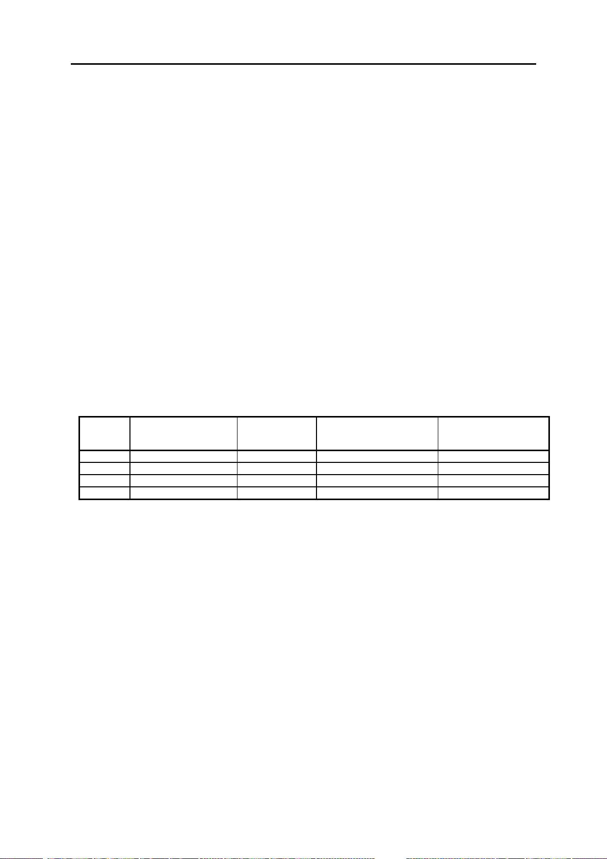
Device Device Model ManufacturerIDKeypad Labeling Mains Voltage
MAC1100
INT GE marquette Icons International 230V
MAC1200
MAC1100
Europe 2 GE marquette Text International 230V
MAC1200
MAC1200 USA GE marquette Text USA 115V
MAC1100
RUSS GE marquette Kyrillian International 230V
MAC1200
Hardware functional blocks:
MAC1100 and MAC1200 comprises of the same hardware functional blocks.
Differences between both are mentioned.
List of the main functional blocks:
Switching power supply
NC Battery for MAC1100 only as an option
PCB NC Battery charge for MAC1100 only as an option
PCB Control CS_CI
PCB Modem Supply CS_M for MAC1200 US device only,
from version V1.1
Printing unit
Keypad
¼ VGA graphics display, monochrome
The description of the functional blocks is valid for MAC1100 and MAC1200.
Differences between MAC1100 and MAC1200 in single functional blocks are
mentioned within the description of such blocks.
Page 9
Marquette Hellige GmbH MAC 1100/1200 V 1.1 Page 9
227 492 20 D - 0002
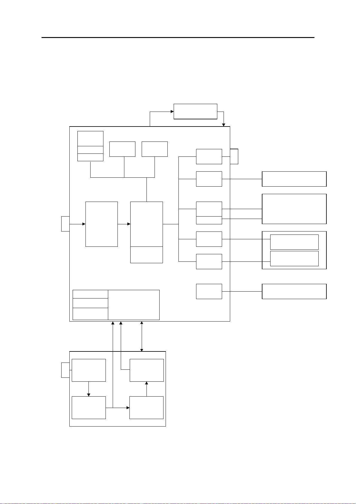
1.1 Block circuit diagram of entire instrument
MAC1100/1200 Version V1.1
PCB Modem Supply
Modem Supply
(MAC1200 US only)
Programm-
Memory
Boot
Loader
Configuration
Memory
Internal
RAM
ECG RAM
buffered
RS232
Driver
RS232
Interface
ECG
Input
ECG
Acquisition
and
Conditioning
Logic Supply
+5V +3.3V
Analog Supply
Printhead
Supply
Controller
Real Time
Device
On/OFF
Control
Core
Clock
buffered
Keypad
Interface
Display
Interface
Display
Supply
Motor
Control
Thermal
Pinthead
Control
Pump
Interface (not
in US Device)
PCB Control CS_CI
Keypad
LCD Grafics Display
1/4 VGA Monochrome
Motor
Thermal Printhead
Printing Unit
Option Pump
(not in US Device)
Line
Power
Input
Line Power
Input
with Fuse
Switching
Power Supply
+26,5V
Line Power, NC Battery
NC Battery
PCB
NC Battery
Charge
MAC1100:
MAC1200:
No Modem Supply,
No buffered ECG RAM,
NC Battery as Option.
Modem Supply in US
device only,
Option Pump not in US
device.
MAC1100/1200
V 1.1
14.01.2000
Page 10

Marquette Hellige GmbH MAC 1100/1200 V 1.1 Page 10
227 492 20 D - 0002
1.2 Mechanical components
The main mechanical components comprise the upper and lower shell of the
MAC1100/1200.
The lower shell serves as a basic unit to receive the following assemblies:
Line power input module with fuse
Switching power supply
NC Battery
PCB NC Battery Charge
PCB Control CS_CI
PCB Modem Supply CS_M
Graphics display
Thermal printing unit
Paper container
The upper shell accommodates the keypad, which is connected to the PCB Control
CS_CI via a 26-pin connector.
The MAC1100/1200 can be opened by releasing 5 screws at the bottom of the lower
shell, opening the paper flap and lifting up the upper shell a little bit to remove the
keypad cable from the PCB Control CS_CI. The upper shell then can be removed
completely.
To replace the NC Battery, the battery flap at the bottom of the lower shell must first
be unlocked with a screw-driver before it can be removed.
The 15-pin input connector to connect the patient cable and the 9-pin connector for
the RS-232 interface are located directly on the PCB Control CS_CI.
Page 11

Marquette Hellige GmbH MAC 1100/1200 V 1.1 Page 11
227 492 20 D - 0002
2 Functional description
The block circuit diagram of the entire instrument in Section 1.1 and the functional
blocks of circuit diagram sheets (P-plans) describe the individual functional blocks.
2.1 Switching power suppl y
The switching power supply generates the fundamental device voltage for the PCB
Control CS_CI and for the PCB NC Battery Charge.
It has the following input specifications:
Input voltage range: 85 ... 264V ac
Line frequency range: 47 ... 65 Hz
The output voltage is +26.5 V dc, the maximum load is 1.5A.
2.2 PCB NC Battery Charge
MAC1200 and MAC1100 with the option “Battery” can operate battery powered. With
a new, fully charged NC battery, in Automatic Mode up to 50 ECG can be recorded.
The PCB NC Battery Charge, controls and monitors the charging process, depending
on the status of the battery and the status of the device.
Section 2.2.1 and 2.2.2 is not valid for MAC1100 without option “Battery”.
2.2.1 Charging circuit for the NC battery
An integrated charging device is used to charge the battery. During charging it
monitors the battery voltage function and switches over from rapid charging to trickle
charging.
Applying the line power to the MAC 1200, or insertion of the battery activates the
charging circuit.
During a recording, the charging current is reduced.
In standby mode, a depleted battery is fully charged within 4 hours.
Page 12

Marquette Hellige GmbH MAC 1100/1200 V 1.1 Page 12
227 492 20 D - 0002
2.2.2 Device behavior depending on the state of battery charge
Depending on the status of the battery and the status of the device, the following
behavior occurs:
State1: Battery depleted, line power supply is connected up:
Battery charged in rapid mode; when fully charged, switchover to trickle
charging.
State 2: Battery full, line power supply is connected up:
Battery charged in rapid mode for some minutes till the charging circuit
recognizes “battery full“, then switchover to trickle charging.
State 3: Battery depleted, no line power supply, device is switched on:
Device inoperative.
State 4: Battery full, no line power supply, device is switched on:
Device fully operative.
When battery is almost depleded, the LEDBAT signal is activated to
Indicate that the device should be charged by connecting to the line
power supply. If the operation is continued without line power, MAC
1200 will shut down itself when a minimum level is reached to prevent
the battery from a excessive discharge.
State 5: Battery depleted, line power supply is connected up, device is switched
on:
Battery is charged in rapid mode, device is fully operative, including
recording.
During recording, the charging current is reduced. If in this phase, a lot
of recordings take place, the battery is not fully charged within 4 hours.
2.3 PCB Control CS_CI
The PCB Control CS_CI is the mainboard of the MAC 1200, the PCB Control CS_C
is the mainboard of the MAC1100, which has not all memory circuit mounted. The
mainboard accommodates the control functions of the device, except the line power
supply and the NC battery-charging controller.
Page 13

Marquette Hellige GmbH MAC 1100/1200 V 1.1 Page 13
227 492 20 D - 0002
2.3.1 Generation of internal power supplies
Logic power supply + 5V and + 3.3V
The processor core and the memory is a fully + 3.3V design.
The interface functions to display, to RS-232, to the printing unit and to the ECG
acquisition unit are supplied with + 5V.
Both the + 3.3V and the + 5V are generated separately by a clock-rated voltage
controller. By using the „adjustable version“ of the voltage controller, both supplies
are based on the same voltage controller. The output voltage is determined by
appropriate dimensioning of the voltage divider at the feedback input of the voltage
controller.
Standby supply + 5VSTB and + 3.3VSTB
The standby supply + 5VSTB supplies the ON/OFF Control, the + 3.3VSTB buffers
the patient ECG memory when the device is turned off.
Both supplies are generated together from one low-power linear regulator with low
quiescent supply current.
Analog supply + 12V
+ 12V is used for the heating control and temperature monitoring of the printing unit,
which requires only a current of a few milliamperes.
This supply is generated by a linear regulator with feedback input.
2.3.2 Switch On/Off circuit
The Switch On/Off Circuit consists of the On/Off Control and the Voltage Control.
The On/Off Control switches the device on or off by switching the device supplies
+UVERS and +USUPPSW.
The On/Off Control is supplied from the + 5VSTB.
Device On Sequence:
The transition from Device Off State, or Standby State when line power is connected
to Device On State can only be activated by pressing the On/Off button.
Device Off Sequence:
The transition from Device On State to Device Off State, or Standby State when line
power is connected can be achieved as follows:
pressing the On/Off button
when the control core activates the signal DEV_OFF,
Page 14

Marquette Hellige GmbH MAC 1100/1200 V 1.1 Page 14
227 492 20 D - 0002
when the voltage control applies the signal REG_OFF_, because the battery
voltage gets too low during battery operation.
The Voltage Control controls the battery voltage during battery operation.
The signal BATT_LEV2 indicates that the battery charge has gone down, and the
device should be connected to the line power soon.
The signal BAT_LEV1 indicates that the battery has been discharged almost
completely, the device should be connected to the line power immediately, otherwise
the device will shut down within few minutes.
If battery discharge is continued without connecting to the line power, the signal
REG_OFF_ is activated and the device is switched off.
2.3.3 ECG recording and front-end processing
The patient input is classified as being cardiac floating and is defibrillation-proof.
The patient leads are connected with a 15-pin connector with a special form for the
specified and released patient cables for the MAC1100/1200.
The main element of the ECG recording and front-end processing is a set of chips
comprising 3 ASICs. Pace detection is realized by a separate circuit.
Every disconnected electrode is detected by a special AC measurement, which
allows higher impedance between electrode and patient.
N common-mode compensation ensures suppression of interference, at the same
time serving to improve the in-phase suppression of the input electrodes.
To protect patients, the ECG recording and front-end processing are assembled as
floating components. Digital signals from and to the controller core are transmitted
via opto-electronic couplers. The floating supply +/- 5V is generated by an isolated
flyback converter from the + 5V logic power supply.
Page 15

Marquette Hellige GmbH MAC 1100/1200 V 1.1 Page 15
227 492 20 D - 0002
2.3.4 Controller core
The actual core comprises the Motorola Power PC MPC821, which contains the
following integrated components:
chipselect logic
DRAM controller
SCC and SMC for RS-232
LCD controller
SPI Interface
I/O ports
Real-Time Clock counter register
In addition, the MPC821 contains a JTAG port with test and programming
capabilities.
The MPC821 has the following additional power supplies:
VDDSYN, filtered from the + 3.3V logic supply, for the clock generation.
KAPWR, generated from the + 3.3V logic supply, or from a battery when device is
off, used for buffering the RTC Counter Register.
The clock generation for the MPC821 is realized by a quartz oscillator with
32.768KHz. The system clock CLOCKOUT is adjusted with the internal PLL register.
The system frequency is 25 MHz.
The Watchdog /Reset Generation is implemented separately in an integrated
system monitoring chip. It has the following functions:
Power-up reset for the MPC821 when the device is switched on
Voltage monitoring of the + 3.3V and + 5V, with reset generation
Watchdog
Switchover to battery supply for patient ECG memory when device is switched off
Signal for access protection for patient ECG memory when device is switched off
The Reset Configuration defines startup conditions like boot port size and clock
generation source.
Four LEDs indicate the device status in addition:
LED1: active when a HRESET_ occurs
LED2: indicator for the logic supply
LED3, LED4: indicate internal software states
The control register comprises device control signals to switch off the device,
control battery charging and display control signals.
The status register contains information on the device hardware configuration and
the state of the battery charge.
Page 16

Marquette Hellige GmbH MAC 1100/1200 V 1.1 Page 16
227 492 20 D - 0002
2.3.5 Real time clock
Since the internal Real-Time Counter Register of the MPC821 is used, no external
Real Time Clock chip is required. The internal RTC Register is buffered by the
voltage KAPWR.
2.3.6 Memory
The complete memory of the MAC1100/1200 is located on the PCB Control CS_C(I).
The software of the device can be loaded through the JTAG Port during the
production process, or for service purposes with the appropriate programming
software through the RS-232 interface.
Program Memory:
Type: Flash, + 3.3V supply
Organization: 1 Mbit x32, 4 Mbyte MAC1100: 0,5Mbit x32, 2 Mbyte
Waitstates: 1 Waitstate
DRAM:
Type: EDO DRAM, + 3.3V supply
Organization: 1 Mbit x32, 4 Mbyte
Waitstates: 0 Waitstate
Patient ECG Memory:
Type: buffered SRAM, + 3.3V supply
Organization: 256 Kbit x16, 512Kbyte MAC1100: No patient ECG memory
Waitstates: 1 Waitstate
Configuration Memory:
The configuration memory is part of the program memory Flash. With special
hardware and software protection facilities, write access to the Flash is only possible
in the defined configuration memory of the Flash. Thus an external configuration
Memory like an EEPROM is not required.
Page 17

Marquette Hellige GmbH MAC 1100/1200 V 1.1 Page 17
227 492 20 D - 0002
2.3.7 LCD graphics display interface
For the LCD interface to the ¼ VGA monochrome LCD interface, the internal LCD
controller of the MPC821 is used.
Controller Interface:
For the digital control signals, delivered from the MPC821, only an output driver is
required.
LCD Power Supply:
The LCD power supply VEE of -23V is generated from the +5V logic supply. The
generation starts after HRESET_ becomes inactive to ensure that the logic supply of
+5V first is applied to the display.
Adjusting Contrast:
Contrast adjustment of the Display is accomplished with the contrast voltage V0. The
level of V0 is controlled with the PWM signal BLCD_CONTR from the timer module
of the MPC821. In addition, the contrast voltage is temperature compensated.
Backlight:
The LCD backlight converter for the CCFL tube is located on the PCB Control
CS_CI too. The backlight converter is generated from the +5V logic power supply.
The signal BLCD_ENBA switches the backlight on or off.
The user can define the backlight active time in the configuration menu.
2.3.8 Keypad interface
The keypad interface contains the control register for 8 keypad columns and the
receiving register for 7 keypad rows, and the control signals for the status LEDs:
LED_LIN, LED_BATT, LED_START and LED_STOP.
Using the matrix of 8 x 7, up to 56 keypads can be detected.
Identification of the key pressed is as follows:
The controller activates a column, activation is via low-level, then the row-register is
read to identify the pressed key by a low-level. This procedure is repeated with the
next column, till all columns have been activated.
Page 18

Marquette Hellige GmbH MAC 1100/1200 V 1.1 Page 18
227 492 20 D - 0002
2.3.9 Printhead control
The printhead controller takes on the complete control of the 216-mm thermal
printhead with a line width of 200 mm.
The output rate to the printhead is 1000 /sec. The resolution in the Y-direction is
8 dot/mm, in the X- time axis up to 40 dots/mm.
Thermal Printhead Dot Control:
The MPC821 prepares a complete dot column and sends it to the FIFO. A complex
PLD reads out a complete column of the FIFO and generates the digital control
signals for the printhead, which are shifted in series.
The duration of heating a dot column is defined through the pulse width of the PWM
Signal HEAT that is generated from the complex PLD too.
In addition, the duration of heating a dot column is influenced by the thermal
printhead monitoring.
Thermal Printhead Temperature Monitoring:
The thermal printhead temperature monitoring measures the temperature of the
thermistor, located on the printhead. A constant current source effects a
temperature-dependent voltage drop.
If a printhead temperature of 55°C is exceeded, the signal REC_OVHEAT_ is
activated and the heating of the printhead is prevented by disabling the signal
STROBE.
Only when the printhead temperature drops below 50°C is the signal
REC_OVHEAT_ disabled and the heating via the signal STROBE re-enabled.
In addition, a continuous reduction of the heating duration occurs with increasing
printhead temperature, resulting in a regular typeface throughout the entire
temperature range.
2.3.10 Motor control
Paper transportation for the speeds 5mm/s, 25mm/s and 50mm/s is driven by a
stepping motor. The stepping motor is controlled by an integrated stepping motor
driver circuit. The current for the motor is adjusted by the sense resistors of the
stepping motor driver.
For the speed 5mm/s, the motor current is reduced, triggered by the signal
LOW_SPEED.
The motor speed is controlled by the frequency of the signal RECTMR_STEP, which
is generated by the timer unit of the MPC821.
The driver circuit is enabled by the signal REC_MOTEN, the driver is powered from
+22,5V.
Page 19

Marquette Hellige GmbH MAC 1100/1200 V 1.1 Page 19
227 492 20 D - 0002
2.3.11 RS-232 interface
The MAC1100/1200 has an RS-232 interface accessible with a 9-pin Sub-D
connector.
Except for the RS-232 driver chip, the interface is integrated into the control core of
the MPC821.
The interface has the following attributes:
hardware handshake with the signals RTS and CTS
or software handshake with XON/XOFF
transmission speeds from 4800 ... 38400 Baud
maximum input voltage range: +/- 15V
minimum driver output voltage: +/- 5V
maximum ESD interface protection: +/- 10kV
From version V1.1, MAC1100/1200 additionally provides a remote start input on the
RS-232 interface. The MAC1200 US device additionally provides a modem power
supply output on the RS-232 Interface.
2.3.12 Buzzer
The buzzer is an integrated signal generator with fixed frequency, directly operating
from the +5V logic power supply.
Activating and deactivating is controlled with the signal SPEAKER.
2.4 PCB Modem Suppl y CS_M
PCB Modem Supply CS_M generates a supply voltage of +8V dc, to operate a
special GE marquette modem direct on the RS-232 interface on the MAC1200
without the need of an external power supply for the modem.
The Voltage is generated by a switching regulator with current limit and thermal
protection from the +26,5V.
The modem supply voltage +8V is accessible on Pin 6 of the RS232 interface.
The protection against ESD is realized with a Transzorb diode on the PCB Control
CS_CI
.
2.5 Internal interfaces
2.5.1 Mechanical interfaces
Mechanical interfaces are described in Section “1.2 Mechanical Components“.
Page 20
Marquette Hellige GmbH MAC 1100/1200 V 1.1 Page 20
y
y
227 492 20 D - 0002
2.5.2 Electronic interfaces
This section describes the pinning, function and significance of the signals on the
internal interfaces of the functional components.
2.5.2.1 Interface to the switching power supply
The interface to the switching power supply is realized by the connector POSUP/ on
the PCB Control CS_CI.
Connector denotation: POSUP/
Type: male connector 1 X 4-pin., 180°, AMP MODU I
reverse terminal protection achieved mechanically.
The function of the individual pins is given in the following table . The definition as an
input/output is seen with reference to PCB Control CS_CI.
POSUP/
Pin
Number
1 +24VPS Input Voltage from power sup.+ 26,5V
2 +24VPS Input Voltage from power sup. + 26,5V
3 GNDPS Input GND from power suppl
4 GNDPS Input GND from power suppl
Signal Name input/output Function Definition
2.5.2.2 Interface to the PCB NC battery charge
This interface has the supply for battery charging, charging control and status
signals and the battery voltage from the PCB NC battery charge.
Connector denotation: BATT/
Type: male multipoint connector 2x 10-pin, 180°
reverse terminal protection and coding with coding pin 15
The function of the individual pins is given in the following table . The definition as an
input/output is seen with reference to PCB Control CS_CI.
Page 21

Marquette Hellige GmbH MAC 1100/1200 V 1.1 Page 21
g
g
g
y
g
y
_
y
227 492 20 D - 0002
BATT/
Pin
Number
1 +24V Output Supply battery chargin
2 +24V Output Supply battery chargin
3 +24V Output Supply battery chargin
4 Code Coding Pin
5NC
6 GND24V common Ground
7 GND24V from power suppl
8 GND24V after ferrite decouplin
9 GND24V
10 +UBATT Input Battery voltage
11 +UBATT Input Battery voltage
12 +UBATT Input Battery voltage
13 +UBATT Input Battery voltage
14 +UBATT_ME Input
15 Code Coding Pin
16 +5V_L Output + 5V suppl
17 NC
18 BATT_OPT
19 LOAD_OFF Output Charging reduction
20 NC
Signal input/output Function Definition
Battery measuring output
Input Status option batter
2.5.2.3 Interface to the LCD Graphics Display
“0“: option active
“1“: reduced charging
The interface to the LCD graphics display provides the LCD data signals, the display
supply voltages +5V and VEE, the display contrast voltage V0 and the display on/off
control signal.
Connector denotation: HOS/
Type: Foil connector, 14- pin, zero power insertion, 180°
The LCD supply voltage VEE can be measured at R 731 on the PCB Control CS_CI,
the LCD contrast voltage can be measured at R 730. Both levels of these voltages
depend on the contrast selected.
The voltage supply for the CCFL tube of the display is provided separately via the
connector BL/.
Caution! Do not touch! High AC voltage!
2.5.2.4 Interface to the keypad
The interface to the keypad is realized with the connector KEYB/. It contains the
signals for the keypad rows and columns, the supply and the control signals for the
status LEDs of the keypad. The foil connecting cable is part of the keypad itself.
Page 22

Marquette Hellige GmbH MAC 1100/1200 V 1.1 Page 22
A
227 492 20 D - 0002
Connector denotation: KEYB/
Type: Foil connector, 26- pin, zero power insertion, 180°,
grid 1.0mm, Molex
2.5.2.5 Interface to the printhead
The control data to the printhead is transferred via the flexible PCB Printhead
Connection, plugged into the connector TPC_DAT/ on the PCB Control CS_CI.
Connector denotation: TPC_DAT/
Type: male connector 1x 20-pin, 180°
Printhead Supply
The printhead is supplied through a 6-pin connection cable, plugged to the connector
TPC_PO/ on the PCB Control CS_CI.
Connector denotation: TPC_PO/
Type: multipoint connector 1 X 6 pin., 180°,
reverse terminal protection, MODU II
The function of the individual pins is given in the following table . The definition as an
input/output is seen with reference to PCB Control CS_CI.
TPC_PO/
Pin
Number
6 COMMON Supply Voltage +22,5V
5 GNDITPC Ground
4 COMMON Supply Voltage +22,5V
3 COMMON Supply Voltage +22,5V
2 GNDITPC Ground
1 VDD1
Signal input/output Function Definition
uxiliary Voltage
Page 23

Marquette Hellige GmbH MAC 1100/1200 V 1.1 Page 23
g
227 492 20 D - 0002
2.5.2.6 Interface to the motor
The motor control signals are supplied through a 6-pin connection cable, plugged to
the connector MOTOR/ on the PCB Control CS_CI.
Connector denotation: MOTOR/
Type: multipoint connector 1 X 6 pin., 180°,
reverse terminal protection, MODU II
2.5.2.7 Interfaces for production tests
Debug Port
The debug port is an interface for developing purposes. With the corresponding
tools, the MPC821 can be set to the debug mode, to show internal states.
Connector denotation: BDM/
Type: male connector, 2x 5- pin, 180 °
JTAG Port
The JTAG is an interface for the production test of the processor core and the
memory. In addition, the Flash memories can be programmed with this interface.
Connector denotation: JTAG/
Type: male connector, 2x 5-pin, 180 °, pin 7: coding pin
The function of the individual pins is given in the following table. The definition as an
input/output is seen with reference to PCB Control CS_CI.
JTAG/
Pin
Number
1TMS Input JTAG Test Mode Select
2TRST Input Reset for Scan Chain “0“: Reset active
3TDI Input Data In for JTAG Mode
4TDO Output Data Out for JTAG Mode
5TCK Input Serial Clock for JTAG
6GND Lo
7 PORESET Bi-direct Power On Reset “0“: Reset active
8 EN BJHRES Input Enable buffered HRESET “0“: HRESET enabled.
9 WE0 IORD Bi-direct Write Enable Flash upper “0” : Write enable
10 WE1 PCDE Bi-direct Write Enable Flash lower “0” : Write enable
Signal input/output Function Definition
ic Ground
Page 24

Marquette Hellige GmbH MAC 1100/1200 V 1.1 Page 24
g
y
227 492 20 D - 0002
In Circuit Programming Port
With the In Circuit Programming Port, both CPLDs can be programmed or updated in
a Daisy Chain queue.
Connector denotation: ISP/
Type: male connector, 2x 5-pin, 180 °, pin 4: coding pin
The function of the individual pins is given in the following table . The definition as an
input/output is seen with reference to PCB Control CS_CI.
ISP/
Pin
Number
1 ISP SCLK Input Serial ISP Clock
2GND Lo
3ISPMODE Input ISP Mode Select
4 Code Coding pin
5 ISP EN Input Enable In Circuit program. “0“: ISP enable
6 ISP SDI Input Serial Data In
7 ISP SDO Output Serial Data Out
8 +5V Logic suppl
9NC
10 NC
.
Signal input/output Function Definition
ic Ground
2.5.2.8 Interface to PCB Modem Supply CS_M
The interface to PCB Modem Supply CS_M is realized by the connectors MO_SU/
and RS232_E/.
MO_SU/ delivers the voltage +26,5 for the modem supply generation, RS232_E/
receives the generated modem voltage +8V for the PCB Control CS_CI.
Connector denotation: MO_SU/
Type: multipoint connector 1 X 3 pin., 180°,
reverse terminal protection, MODU II
The function of the individual pins is given in the following table . The definition as an
input/output is seen with reference to PCB Control CS_CI.
Page 25
Marquette Hellige GmbH MAC 1100/1200 V 1.1 Page 25
y
y
)
)
V
V
227 492 20 D - 0002
MO_SU/
Pin
Number
1 +UVERS Output Supply Voltage + 26,5V
2 EN_MOSU Output Enable Modem Supply Open, high: enable
3 GND24V Output Ground
Signal input/output Function Definition
Low: disable
Connector denotation: RS232_E/
Type: male connector, 2x 5-pin, 180 °
The function of the individual pins is given in the following table . The definition as an
input/output is seen with reference to PCB Control CS_CI.
RS232_E/
Pin
Number
Signal input/output Function Definition
1+5V Output Logic Suppl
2+5V Output Logic Suppl
3 GND Ground
4 GND Ground
5SMRXD1 Input Receive (RXD
6SMTXD1 Output Transmit (TXD
7 GND Ground
8
9 EKGTRIG E Output ECG Trigger Reserved
10 FERNST E Input Remote Start Input Reserved
MODEM Input Modem Supply +8
Reserved
Reserved
Reserved
Reserved
2.6 Interfaces to peripherals
The MAC1200 has only 3 interfaces for peripherals:
Mains input
Patient input
RS-232 interface
The mains input interface on the device is a 3-pin standard cold appliance socket
connection, which is integrated into the mains input module. Connection to the mains
is effected via a 3-pin power cord with a non-fused earth conductor.
The mains input is a wide range input from 95Vac ... 240Vac. The mains input
module contains the two primary fuses.
Page 26

Marquette Hellige GmbH MAC 1100/1200 V 1.1 Page 26
g
V
V
y
227 492 20 D - 0002
When replacing these fuses, the following points have to be observed:
replacement by factory or servicing agent only!
disconnect mains plug!
replacement only with the original fuses!
For the patient input, the mechanics of the patient input of the MAC500 is used, so
the patient cables of the MAC1000/CardioSmart cannot be used for the MAC1200.
A 9-pin sub-D Connector, type Mark II with 4-40 UNC inserts, with a standard
configuration of the signals TXD, RXD and GND is implemented in the construction
of the RS-232 interface.
2.6.1 Electronic interfaces
2.6.1.1 RS-232 interface
The 9-pin sub-D Connector of the RS-232 interface is implemented on the PCB
Control CS_CI directly.
From Version V1.1, the remote start input pin is available on pin 8.
In MAC1200 US devices the modem supply output +8V is available on pin 6
additionally.
Connector denotation: RS232/
Type: 9-pin sub-D, female, Mark II with 4-40 UNC inserts
The function of the individual pins is given in the following table . The definition as an
input/output is seen with reference to PCB Control CS_CI.
RS232/
Pin
Number
Signal input/output Function Definition
1NC
2RXDE Input RS232 Data In
3TXDE Output RS232 Data Out
4NC
5GND Si
6
7RTSE Output Request to Send
8 FERNST Input Remote Start Input “0” : active
9NC
MODEM Output Modem Supply +8
nal Ground
MAC1200 US onl
Page 27

Marquette Hellige GmbH MAC 1100/1200 V 1.1 Page 27
g
(RA)
)Inp
)Inp
g
)
g
227 492 20 D - 0002
2.6.1.2 Patient input
The connection to the patient cable is realized with a 15-pin female sub-D
Connector, implemented on the PCB Control CS_CI directly. The mechanical plastic
housing makes sure that for MAC1100/1200 only released patient cables can be
connected.
Connector denotation: EKG/
Type: 15-pin sub-D, female
EKG/
Pin
Number
1C2 Input chest lead V2
2C3 Input chest lead V3
3C4 Input chest lead V4
4C5 Input chest lead V5
5C6 Input chest lead V6
6 Shieldin
7 Cable Input Identification: patient cable
8 Cable identification Input 5/10 -pin or 12 -pin cable
9R
10 L (LA
11 F (LL
12 C1 Input chest lead V2
13 NST Input Nehb electrode NST
14 N (RF
15 NAX Input Nehb electrode NAX
Signal input/output Function Definition
Output shielding AVSS
used
used
Input electrode right arm
ut electrode left arm
ut electrode left le
Output electrode right le
“0“: patient cable used
“0“: 12-pin cable
“1“: 5- or. 10-pin cable.
Page 28

Marquette Hellige GmbH MAC 1100/1200 V 1.1 Page 28
227 492 20 D - 0002
2.7 Software Updates
Software updating can be performed via RS232 with the Software Download Kit
part-No. 2000079-001. The required connection cable and a description of the
procedure is included in the kit.
2.8 Limitations
The following operating modes are not implemented in the MAC1100/1200:
No ergometry
No SAO2
No spirometry
No late potentials, no RR variability
No phono, no US Doppler
A scope output is not available.
No analog inputs.
No ECG trigger output.
Lead acid accumulators cannot be used.
Primary cells cannot be used.
Page 29

Marquette Hellige GmbH MAC 1100/1200 V 1.1 Page 29
227 492 20 D - 0002
3 System test functions
All messages displayed during the sel f-test are i n Eng l is h.
3.1 General information
The functions for the system test are mostly menu-guided.
For complete execution so me tests require special auxiliary resources. These include
interface testers or PC, connection cables, signal generators, etc. The tests that are
necessary are described in the vari ous test descr ipti ons.
3.2 Test start
After simultaneously pressing the key s
Shift + 12 Lead (or Auto)
the initial display menu appears to enable sel ecti on of a specific test. (see bel ow)
The specific test functions are activated by pressing the corr esponding key.
Hardware tests
1= Display test
2 = Keyboard
3= Motor test
4= Test results
5= Recording test
6= V24 tests
7= Time and date
8= Electrode test
9= Time constant
D= Device model
H= Interpretation
P= Pace enhance
N= Serial number
X= End (Terminate hardware tests)
Page 30

Marquette Hellige GmbH MAC 1100/1200 V 1.1 Page 30
227 492 20 D - 0002
3.3 Display test
After pressing the “1" key the following menu appears:
Display test
(1) Test pattern
(2) Clear display
(3) Restore menu
(4) Inverse
(5) Display illumination
Contrast control
- Shift_Cursor_Down
- Shift_Cursor_Up
Terminate with any key
Pressing any other key than one of those listed in the menu above leads back to the
initial display menu.
(1) Test pattern
Pressing this key generates a chessboard pattern. Each subsequent pressing
generates the inverse display of its predecessor .
(2) Clear display
All display pixel s ar e inacti ve
(3) Restore menu
The initial display test menu is displ ay ed.
(4) Inverse
The contents of the existing display appear in r everse video.
(5) Display illumination
The illumination is switched on or off by pressing this key.
Contrast control
The contrast setting can always be adjusted as descr i bed abov e ( cur sor keys).
Page 31

Marquette Hellige GmbH MAC 1100/1200 V 1.1 Page 31
227 492 20 D - 0002
3.4 Keyboard test
By pressing the “2" key the following menu appears:
Key T e s t
B= Bleeper test
E= End
When a key is pressed this key or its function is displayed. This can either occur by a
triple character display, e.g., “AAA” or as a text, e.g., "CURS_UP". Moreover, pressing
the “B” key tests the bleeper (audible sound). The keys “ALT” and “SHIFT” only in
combination with another key. The “E” key terminates this test and simultaneously
undergoes a self-test.
3.5 Motor test
When the “3" key is pressed the following menu appears:
Motor Speed Test
- Speed selection key
- Start/Stop key
Terminate with any key
The speed select key is used to set the required speed and the motor i s set into motion
with Start/Stop.
A marking pulse is set once every second. The running speed can then be calculated
or its accuracy checked from the distance between marking pulses. Any other key
pressed not included in this menu leads to the initial displ ay menu.
Page 32

Marquette Hellige GmbH MAC 1100/1200 V 1.1 Page 32
227 492 20 D - 0002
3.6 Test results
Pressing the “4" key tr i g g er s the output of the test results.
The output of the test protocol supplies the following information:
Time and date
Device serial number
Device model
Software release
ECG time constant
Battery voltage
test results
Memory used (ROM, RAM)
base address
size
Following output, the initi al di spl ay menu reappears automatically.
The identification of the Hardware Version is given by the item “Remote Control
yes/no”.
“No” indicates Hardware Version V 1.0 (no remote control), “yes” indicates
Hardware Version V 1.1.
This message is intended only for the use of the individual or entity to which it is addressed. As it contains
confidential information, any use distribution or copying is strictly prohibited if you are not the addressee.
3.7 Self-test
The test results elucidated in Section 3.6 are ascertained during the self-test, which is
always performed on power-up. Should errors be detected, a message appears on the
display after the test, indicating the possible errors. The following error codes are used
to identify the error.
Error codes
The following error codes appear on the display together with the message “Self-test
failed”:
ERROR_CODES: 0 - reserved
1 VEKT - error in vector table
2 DRAM - DRAM error
3 SRAM - SRAM error
4 - reserved
5 - reserved
6 - reserved
7 - reserved
Page 33

Marquette Hellige GmbH MAC 1100/1200 V 1.1 Page 33
227 492 20 D - 0002
8 ROMB - ROM error (checksum) in the FLASH
9 - not used
10 - not used
3.8 Recording test
The recording test is activated by pr essing the "5" key.
A window wi th 2 channels i s di spl ay ed.
- speed select key: selects the speed
- start/stop key: starts and stops a real time 2 channel recording
The selected speed and sensitivity is displ ayed.
Terminate with any key.
3.9 V24 tests
Several possibilities are available to test the serial interface. Moreover, on the one
hand, the signal transmission and receiving of the interface can be tested by an
internal feedback from TXD and RXD and, on the other hand, the signal transmission
and receiving wi th a r emote station.
For the test with a remote station, the connection cable from MAC 1100/1200 to PC,
PN 223 362 03 is required. In addition, the following transmission protocol should be
adjusted at the remote station:
1 start bit, 8 data bits, no parity
1 stop bit
Baud rate 19200
Pressing the “6" key cal l s up the foll owing menu:
Interface test
1= Sending and receiving
2= Send test string to device
3= Send/Receive with device
A = Abort (terminate i nterface test)
Page 34

Marquette Hellige GmbH MAC 1100/1200 V 1.1 Page 34
227 492 20 D - 0002
(1) Sending and receiving
This test enables complete testing of the RS232 signal path for transmitting and
receiving, including R S232 dr iver and connector.
This test requires an RS232 connector with an internal bridge from pin 2 (RXDE) to pin
3 (TXDE). Depending on the result of the test, the follow i ng messag e appear s:
If test result is OK: Out :Hello world!
In :Hello world!
If an error occurs: Out :Hello world!
In : ERROR (In)
(2) Send test string to device
In this test a remote station, e.g., PC must be connected up and have a terminal
program which can receive signals and be configured for the above-mentioned
protocol. If the remote station is on receive, then every time the “2" key is pressed the
test string “Hello world!” is transmitted to the remote station. Simultaneously, the
following message appears on the display:
v24-Settings: “19200, 8, n, 1“
Out: Hello world!
(3) Send and receive with device
Sending and receiving can be tested with a remote device by pressing the “3" key.
The device should be connected as described in (2).
After pressing the “3" key a test string is sent to the remote station. The following
message appears on the display:
Transmitting: Hello world!
Receiving: [ ]
A subsequent input at the remote station is sent back to the device and displayed
there. Moreover, it should be noted that an input must take place within 10 s and the
input terminated with “return” .
Page 35

Marquette Hellige GmbH MAC 1100/1200 V 1.1 Page 35
227 492 20 D - 0002
3.10 Time and date
This section deals with the quick checking and setting of the time and date.
Pressing the “7" key calls up the following display:
Time (hh:mm) [18:25:29]
and
Date (dd.mm.yyyy) [03.03.1999]
X = End
To set time or date, select the corresponding time or date field by pressing the return
key. During entering the numbers, a single cursor is not displayed.
3.11 Electrode test
The electrode test is started by pressing the “8" key.
The following menu is display ed:
Electrode test
Terminate with any key
Select pace electrode (key ‘P’)
Pace electrode LA
Cable = 10 electrodes (or no cable)
The status of each electrode is displayed. Electrode OK or disconnected is displayed
as follows:
Status = 0 -> Electrode OK
Status = 1 -> Electrode disconnected
With the “P” key, the pace electrode can be selected. The selected pace electrode is
displayed.
The status “cable” indicates if a cable is connected to the patient ECG input or not.
Page 36

Marquette Hellige GmbH MAC 1100/1200 V 1.1 Page 36
227 492 20 D - 0002
3.12 Time constant
By pressing the “9" key, the ti me constant for the ECG patient i nput can be sel ected.
The following menu is display ed
1= 1.02s ( frequency 0,16Hz )
2= 2.04s ( frequency 0.08Hz )
3= 4.08s ( frequency 0,04Hz )
X = End
The currently selected time constant appears in reverse video. Use key 1 ... 3 for
selection.
The factory setting is 2.04s. This should only be changed when deemed really
necessary..
3.13 Setting the device model
The setting of the device model is activated by pressing the “D” key, the following
display image appears:
D e v I c e model
1= INT
2= USA
3= Europe 2
4= ASIA (not available from version V1.1)
5= RUSS
X= End
Warning!
Changing the device model affects the selection of the output formats and
languages available, can switch the program for Interpretation from HEART to 12
SL, or vice versa. Also affected are the default configuration settings, e.g.,
override function yes/no, line f ilt er 50/60 Hz.
The device model configured during manufacture should only be changed when
deemed really necessary .
Page 37

Marquette Hellige GmbH MAC 1100/1200 V 1.1 Page 37
227 492 20 D - 0002
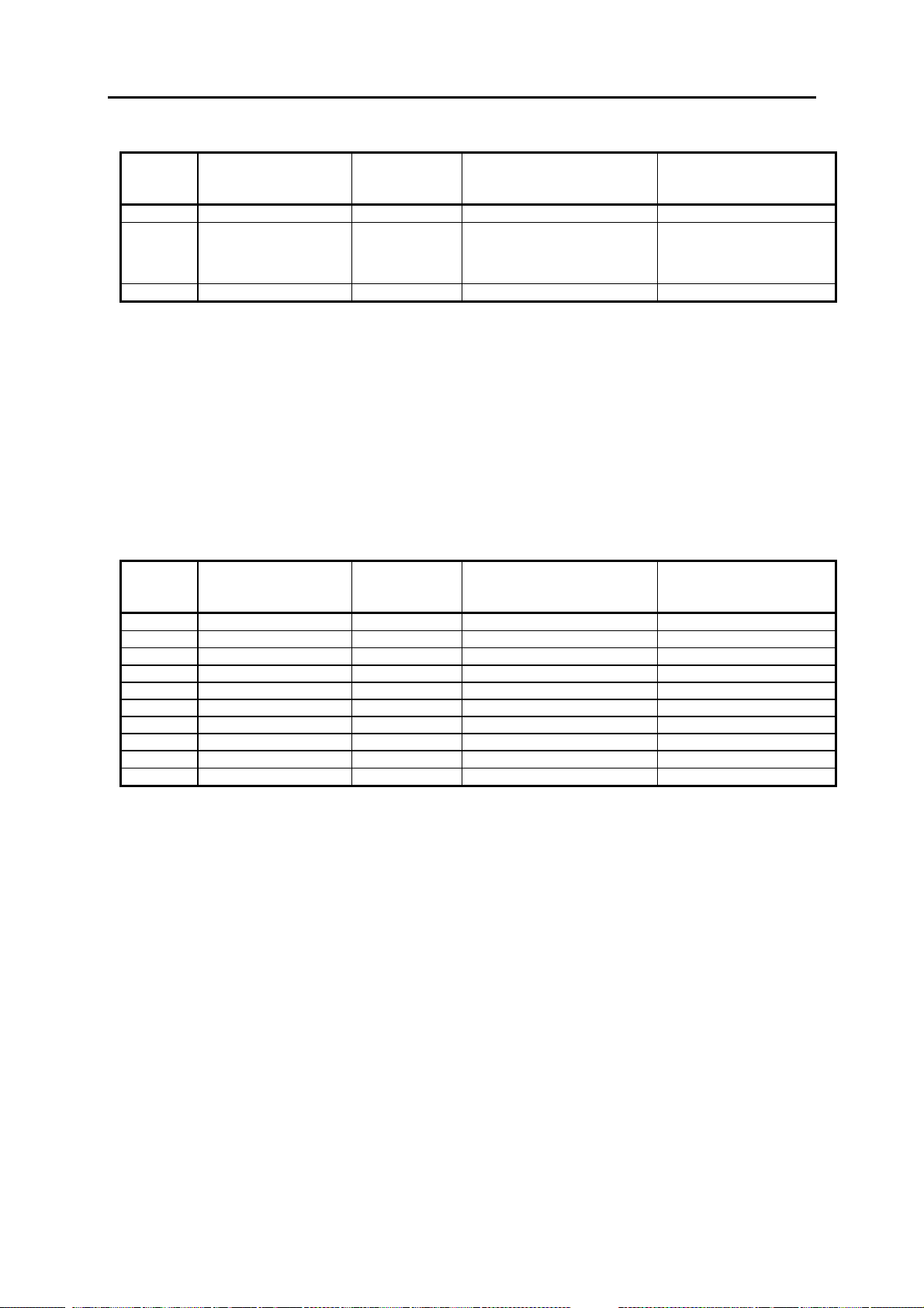
The following table shows the most important combi nations:
Device
model
Inter-
pretation
Output
formats
Languages Default settings
Override
Line filter
function
enabled
01 INT HEART international international no 50 Hz
02 USA 12SL USA e,f,s yes 60 Hz
03 Europe2 12SL inter nati onal international yes 50 Hz
04 ASIA *) HEART international international no 50 Hz
05 RUSS HEART international g,e,f,r,hung,
no 50 Hz
czech
- Language international: g, e, f, i, s, por, sw, nor, fin, dan, hol, czech, hung
- Europe 2: United Kingdom, Benelux , Scandinavia
*) not available from vers ion V1.1
The required device model is selected by pressing the appropriate key, “1" to “5".
Quit selection menu by pressing the “X“ key.
Quit the self-test with “X” key.
MAC 1200 configures the appropriate items and initiates a cold start automatically.
Thus, when the device is rebooted automatic all y all the new settings are adopted.
Selecting a particular device model leads to the configuration of the program for
Interpretation as indicated in the table above, even when the interpretation program
was configured differently beforehand as described in Section 3.14.
Note on saved ECGs when configuring the device model:
Saved ECGs are not lost.
If a new device model is selected, the program for Interpretation is switched over;
however, when printing out the saved ECGs the display in the status line (12SL, or
without in the case of HEART) is related to the currently enabled program for
Interpretation, although the results are based on the program previously configured. In
this case, the saved ECGs should be printed out or transferred to a PC before
configuration of the new model.
Page 38

Marquette Hellige GmbH MAC 1100/1200 V 1.1 Page 38
227 492 20 D - 0002
3.14 Switching over the program for interpretation
Switching over the program for interpretation is activated by pressing the “H” key, the
following display i mag e appears:
I n t e r p r e t a t i o n
1= HEART
2= 12SL
X= End
The currently enabled interpretati on program appears in reverse v i deo.
Warning!
Switching over to another program for Interpretation affects the measurement
results and the interpretation!
The program for Interpretation configured during manufacture should only be
changed when deemed really necessary!
The required program for Interpretation is selected by pressing the appropriate key,
“1" or “2".
Quit the selection menu by pressing the “X” key.
Quit the self-test with the “X” key.
MAC 1200 configures the appropriate items and initiates a cold start automatically.
Thus, when the device is rebooted automatic all y all the new settings are adopted.
Note on saved ECGs when switching over the program for Interpretation:
Saved ECGs are not lost.
After switching over to a different program for Interpretation when printing the saved
ECGs the display in the status line (12SL, or without in the case of HEART) is related
to the newly selected interpretation program, although the results are based on the
program previously configured. In this case the saved ECGs should be printed out or
transferred to a PC before switching ov er to the new program for Interpretation.
Page 39

Marquette Hellige GmbH MAC 1100/1200 V 1.1 Page 39
227 492 20 D - 0002
3.15 Pace enhance
Pressing the “P" key call s up the foll owing menu:
P a c e enhance
1= ON
2= OFF
X= End
The currently selected pace display mode appear s i n reverse video.
ON: Standard pace display mode.
Detected pace pulses are displayed as special defined pulses
OFF: Pace pulses are displayed with there own pulse form directly
The factory setting is ON. This should only be changed when deemed really
necessary.
3.16 Serial number
The serial number of the device is displayed by pressing the “N” key.
The serial number is only displayed and cannot be changed.
The serial number is entered during the manufacturing process.
After replacing the PCB Control CS_CI, during the power up sequence, the serial
number of the device has to be entered.
Terminate with the “X” key.
Page 40

Marquette Hellige GmbH MAC 1100/1200 V 1.1 Page 40
227 492 20 D - 0002
Page 41

Marquette Hellige GmbH MAC 1100/1200 V 1.1 Page 41
227 492 20 D - 0002
4 Repair instructions
4.1 Safety instructions
Repairs may only be conducted by approved specialist personnel.
Before opening the MAC 1200, switch off device and disconnect mains plug!
Never connect mains plug when the device is open!
Before replacing the primary fuses in the power input module, the device should
also be switched off and the mains plug disconnected!
For replacing components, only the original Marquette components, mentioned
in the spare parts list may be used!
When replacing electronic components implement ESD protection.
Return replaced PCBs in ESD packaging only .
Defective NC batteries or empty batteries should be disposed of in accordance with
the applicable legal stipulations or returned to the factory.
Batteries returned to the factory should be labeled “For disposal”.
4.2 Replacing components
For all the following points the safety instructions in Section 4.1. have to be
observed!
Warning: The device has to be switched off!
Opening the device
To open the MAC 1200 release the 5 fastening screws on the underside of the device,
open the paper feed flap, carefully raise the upper shell of the housing, disconnect
keypad cable by opening the connector KEY B/ on the PC B C ontr ol.
The display remains in the lower shel l of the casing.
During reassembly, ensur e that no cables ar e pi nched.
Page 42

Marquette Hellige GmbH MAC 1100/1200 V 1.1 Page 42
227 492 20 D - 0002
Replacing the primary fuses in the mains input module
Warning: Only use fuses indicated on the rating label! ( see Secti on 8, Parts Li st)
Replacing the battery
Disconnect and lift out the battery compartment on the underside of the device by
raising the middle fastening catch. Remove the battery and disconnect the battery plug
BATT_IN/ from the PCB Battery Charge.
Warning: Only original Marquette batteries may be used! (see Section 8, Parts
List)
Defective NC-batteries or empty batteries should be disposed of in accordance with
the applicable legal stipulations or returned to the factory.
Batteries returned to the factory should be labeled “For disposal”.
Before putting in the new battery, insert plug BATT_IN/. Push in battery compartment,
secure by pressing on the fastening catch.
Replacing the PCB Battery Charge
After opening the device, first of all open the battery compartment and disconnect the
battery connector BATT_IN/ (see "Replacing the batter y ” ) .
Then disconnect the connector BATT/ from the PCB Control. Undo the fastening
screw next to the inductor L1 on PCB Batter y C har g e.
PCB Battery Charge has one solder ed fuse:
SI 1: Battery fuse
No adjustments on the PCB Battery Charge ar e necessar y .
Replacing the PCB Control
Before replacing th e PCB, if still possible, printout the settings configured b y the user
and check the options enabled.
After opening the device first of all disconnect the plug-in connector POSUP/ to the
power supply unit, and the connector BATT_IN/ from the PCB Battery Charge. Make
sure that the connector BATT_IN/ makes no contact with the coated shell, while
disconnected. Then disconnect the remaining connectors to the recording unit. Undo
the 6 PCBs fastening screws.
Page 43

Marquette Hellige GmbH MAC 1100/1200 V 1.1 Page 43
227 492 20 D - 0002
Check whether the connection LOET2 of the lithium battery for the real-time clock
(BA1) is correctly soldered. Also check whether the connection LOET1 of the backlight
inverter is soldered corr ectly.
Insert new PCB, fix the fastening screw s and plug in connectors.
Connect keypad in the upper shell to connector KEYB/ and close connector on PCB
Control and set the upper shell on to the lower shell . Tig hten the 5 fastening scr ews.
Load the software via RS-232 interface with the Software Download Kit part No.
2000079-001.
Enter the device serial number.
If required, enter the option codes as described in the Operator’ s M anual .
Adjust the display contrast.
Setting the date and time (Section 3.10).
If known, adopt the user-programmed configuration; other wise, default setting.
If known, reset the user-programmed time constants, otherwise setting to default of
2.04s (Section 3.1.12). Check the time constant by outputting the self-test results
(Section 3.1.6).
Replacing the motor
After replacing the motor, no adjustment of speed is necessary. Nevertheless run the
motor test (Chapter 3.5).
Replacing the graphics display
After opening the device first of all open connector KYO/ and release the flat ribbon
cable of the display. Undo the screws of both plastic display holders, shift it 2 mm in
the direction to the handle and lift up display and holders. Disconnect the plug
HOS_BL/.
To re-assemble do vice-versa.
Adjust the contrast with the new display.
Page 44

Marquette Hellige GmbH MAC 1100/1200 V 1.1 Page 44
227 492 20 D - 0002
Page 45

Marquette Hellige GmbH MAC 1100/1200 V 1.1 Page 45
227 492 20 D - 0002
5 Troubleshooting tips
For all the following points the safety instructions in Section 4.1. have to be
observed!
Device cannot be switched on even though power plug is plugged in
- green power lamp LED is off and devic e cannot be swit ched on:
- Power cable defective or not plugged in cor r ectly?
- Primary fuses in the mains input module defective?
- Connector from the mains input module to the mains switching power supply
plugged in correctly , or cabl e defectiv e?
- Connector from the mains switching power supply to connector POSUP/ on the
PCB Control plugged in corr ectl y , or cabl e defectiv e?
- Keypad via connector KEYB/ on PCB Control plug g ed i n cor rectl y?
- 26,5V on the connector POSUP?
if no: - mains switching power suppl y defectiv e
if yes: - PCB Control defective
- or keypad defective
- green power lamp LED is on, but device still cannot be switched on:
- PCB Control defective
- or keypad defective
Device cannot be switched on when being battery-operated only
- Is the battery depleted?
- Plug in power plug, g r een power lamp LED should glow and the device can be
activated,
if not: - refer to "Device cannot be switched on even though power
plug is plugged in”.
- By connecting the power plug, rapid charging is activated, LED1 on the PCB
Battery Charge is activated
if not: - PCB Battery Charge is defective
- With power plug plugged in, let unit charge for 10 minutes, then disconnect
power plug. Can the devi c e be switched on and can a recording be started?
if yes: - Function OK., continue loading with plugged mains plug
if not: - Battery disconnected or cable defective?
- Battery defective (no capacity)?
- PCB Battery Charge defective ( Si1?)?
Page 46

Marquette Hellige GmbH MAC 1100/1200 V 1.1 Page 46
227 492 20 D - 0002
No display on the screen
- Does the yellow Stop LED on the keypad glow after the device is sw i tched on?
if not: - refer to "Device cannot be swi tched on ....”
if yes: - continue
- Does a beep sound approx. 10s after switching on the MAC1200 occur (indicates
the successful power up self-test)?
if not: - Self test error, PCB Control defective
if yes: - continue
- Contrast badly adjusted?
- Can the background illumination be activated by pressing a key?
- Can the display test in Section 3.3 be applied successfully?
if not: - graphics display modul e defective
- or PCB Control defective
Error in self-test identified
When an error is detected during the self-test, in addition to the message “Self-test
failed”, the error code number and a short description also appear on the display. The
meaning of the error codes is described in Section 3.7. The error codes refer to the
PCB Control, and should be noted as information for the servic e center.
MAC 1200 fails to give printout, no paper transport
Perform the following test in the 6-l ead operati ng mode:
- Paper available? Paper correctly inserted? Paper transport problems (jam) ?
- Paper feed flap correctly engaged on both sides?
- After pressing the start key, the green start Led must g l ow
if not : - keypad defective? Apply keypad test in Section 3.4
if yes: - continue
- Paper feed flap correctly engaged on both sides?
- Mark reader defective or not plugg ed i n?
- All connections for printhead and Motor are plugg ed i n?
- Motor blocked ? (check roller, transmission)
- Operating only on battery which is strongly depl eted?
if yes: - plug in power plug
if not: - PCB Control defective
Page 47

Marquette Hellige GmbH MAC 1100/1200 V 1.1 Page 47
227 492 20 D - 0002
Paper transport functions, no printout
- Paper feed flap correctly engaged on both sides?
- All connectors for printhead plugged in?
- Operation with strongly depl eted battery?
if yes: - plug in power plug
if no: - PCB Control defective
- or printhead defective
MAC 1200 only prints on the upper or lower section of the printout
- Paper feed flap is only engaged on one side.
MAC 1200 prints, but only baselines are printed out
- Electrodes applied correctly?
- Electrode cables plugged into the patient trunk cable ter minal -box correctly?
- Patient trunk cable defective ( e.g., RL defective)?
- Contact problems at the patient input connector of the MAC1200?
if not: PCB Control defective.
Page 48

Marquette Hellige GmbH MAC 1100/1200 V 1.1 Page 48
227 492 20 D - 0002
Page 49

Marquette Hellige GmbH MAC 1100/1200 V 1.1 Page 49
227 492 20 D - 0002
6 Adjustment instructions
For MAC 1200 no adjustment of components is required.
When PCB Control CS_CI, or the graphics display has been exchanged, the display
contrast should be adjusted to an optimum contrast ratio as described in the user
manual.
Page 50

Marquette Hellige GmbH MAC 1100/1200 V 1.1 Page 50
227 492 20 D - 0002
Page 51

Marquette Hellige GmbH MAC 1100/1200 V 1.1 Page 51
227 492 20 D - 0002
7 Servicing and maintenance
7.1 Technical inspection
A technical inspection is to be performed once a year. The following items, including
the accessories used, are to be performed:
- Check device and accessories for mechanical defects, whi ch i mpair their function.
- Perform a function check as detailed in Section 3 “System test functions”.
- Check labels and inscriptions on the devi ce r elati ng to safety ar e clear l y l eg i ble.
- Measure the Protective Earth Resi stance (s ee Section 7.1.3 /7.1.3.2) .
- Measure the enclosure Leakage Current ( s ee Section 7.1.3 /7.1.3.3.1) .
- Measure the patient leakage current ( see Secti on 7.1.3 /7.1.3.3.2).
Warning!
The following checks may only be performed by persons whose training,
knowledge and practical experience enable them to carry out such checks
reliably and correctly !
Notes:
The operational and functional reliability of the device is checked using the following
checklists.
They serve the experienced technici an when checking the device.
A knowledge of device operati on as detail ed i n the “ Oper ator’ s M anual ” i s assumed.
The checklist items are based on the testing instruments gi v en bel ow.
The tests should be carried out using the customer’s accessories, so that defective
accessories are also detected automatically.
If other testing instruments are used besides those mentioned, the items on the
checklist and tolerance specifications may need to be modified.
7.1.1 Visual check
Device and accessories are to be checked to ensure that
- fuse cartridges comply wi th vendor’s specifications;
- labels and inscriptions on the devic e rel ating to safety are clearly legibl e;
- the mechanical state of the device permits its further use;
- there is no fouling which coul d cause any reduction in safety.
Page 52

Marquette Hellige GmbH MAC 1100/1200 V 1.1 Page 52
227 492 20 D - 0002
7.1.2 Test functions
7.1.2.1 Recommended testing instruments and accessories
1x Multi-parameter simulator Lionhear t
1x RS232 interface connector with internal connection between pins 2 and 3
(TXD and RXD)
1x Patient trunk cable and customer electrode leads,
or 1X p a tient t runk ca b le, 10- p in 223 387 01
7.1.2.2 Test preparations
In general, the device test functions implemented in M AC 1200 ar e used for the tests.
These are described in Section “3. Device test functions”.
Connect MAC 1200 up to the mains, the green LED for standby must g l ow.
Switch the device on, the self-test runs automati cal l y , no er r or messag e should appear.
When the self-test has finished the device is in the automatic mode, the yellow LED for
still disabled operating mode must glow.
Modifications in the user-programmed configuration may need to be made in order to
carry out the test. Should such a change need to be made to enable testing, make a
printout of all the modified configuration lists and mar k the chang es made.
Important: After completing the test the original user-programmed configuration is to
be retrieved and activated.
7.1.2.3 Operating and display unit performance tests
- Carry out the “D is play test (1)” as detailed in Sections 3.3, respectiv ely.
- Carry out the “Keypad test (2)” as detail ed i n Sections 3.4, r espectively.
Page 53

Marquette Hellige GmbH MAC 1100/1200 V 1.1 Page 53
227 492 20 D - 0002
7.1.2.4 Test for recording speeds 25 and 50 mm/s
- Carry out the “Motor test ” as detailed in Sections 3.5, respectively .
- The feed speed deviations should be less than 3%.
7.1.2.5 Device Test result check
- Output “Test results ” as detailed in Sections 3.6, respectively.
- Main parameters: - all memory stores free from error ?
- ASIC test O.K?
- Sample rate 1000?
- Selected time constants: 2.04 s (or 4.08 s)?
- Printhead voltage > 18V, batter y char g e O.K?
- Printout clearly leg i ble and without any lapses or interference?
7.1.2.6 RS-232 interface test
Carry out the “Interface test ” test item “( 1) Transmi tti ng and r eceiving”, as detailed in
Section 3.9, respectively.
7.1.2.7 Analysis of the ECG signals and HR value
Carry out the following setting s on the EC G si mulator :
- Amplitude 1 mV
- Heart rate (RATE) 60 bpm
Connect the electrode leads as indicated below:
R, red (or RA) -----> RA
L, yellow (or LA) -----> LA
F, green (or LL) -----> LL
N, black (or RL) -----> RL
C1, white/red (or V1 ) -----> V1
: : :
:::
C6, white/violet (or V6) -----> V6
Switch in 6 lead operating mode and start recording by pressing the Star t key .
By pressing the lead scrolling key, check whether all leads are being recorded.
The ECG traces must be noise-free.
Page 54

Marquette Hellige GmbH MAC 1100/1200 V 1.1 Page 54
227 492 20 D - 0002
Record one page in the “6-lead” operating mode. The following annotations must be
present:
- Heart rate (top right)
- Lower status line - date and time
- recording speed
- sensitivity
- active filter, e.g., 50/60 Hz , 40/20 Hz, ADS
- frequency range of the recording
The heart rate of 60 bpm +/- 2 bpm appears on the display and is printed out on the
recording.
Activate the square-wave function on the ECG transmitter at 1 mV.
Using the lead scrolling key select lead II. The square-wave pulse trace must
correspond in amplitude with the displayed 1 mV reference pulse (applicable to
named transmitter only).
Switch back to ECG signal on the ECG transmitter.
Start the recording in manual mode.
Increase the heart rate to 200 bpm on the ECG transmitter. The acoustic warning
signal must sound for about 1s. Reduce the heart rate back to 60 bpm, the warning
signal no longer sounds.
7.1.2.8 Pacemaker identification test
Make the following settings on the multi function simul ator:
- pace setting
- pace amplitude 6 mV
- pace duration 0.2 ms
Adjust “6-lead mode” on MAC 1200 devi ce to be tested and sel ect l ead g r oups I, II
and III.
Start the recording. The pace pulses must be visible as needles on the recording
output.
Page 55

Marquette Hellige GmbH MAC 1100/1200 V 1.1 Page 55
227 492 20 D - 0002
7.1.2.9 Identification of disconnected electrodes
Reset the simulator to ECG signal at a heart rate of 60 bpm. Remove one electrode
after the other from the ECG transmitter.
Activate the “12 lead” mode in the MAC 1200 device to be tested without activating it
by pressing the Start key.
Check to ensure that each disconnected electrode is displayed correctly and that an
acoustic alarm signal sounds.
7.1.2.10 Checking the charge status of the NC battery
The NC battery can, among other things, be checked as follows:
discharging the battery, followed by charging up completely (duration 4 h), followed by
discharging in standby mode without recording.
If the operating time for this procedure is under 2.5 h, the battery should be replaced.
7.1.3 Safety Analysis Tests
7.1.3.1 General information
The suggested Safety Analysis Tests refer to the international standar d IEC 601- 1.
The tests are generally performed wi th Safety Testers, on most of them, the measuring
circuits according IEC 601 are al ready implemented.
The following is a general description of the tests to be performed. For the handling of
your Safety Tester follow the user manual.
The tests may be performed under normal ambient conditions of temperature, humidity
and pressure and with line v olt ag e.
The leakage currents correspond to 110 % of rated voltage for the tested unit. Most
Safety Testers take this into account, otherwise the measured values have to be
calculated.
Recommended Test Equipment
- Safety Tester for measurements according to IEC 601.
- Testing connector according to the following descri ption.
Page 56

Marquette Hellige GmbH MAC 1100/1200 V 1.1 Page 56
227 492 20 D - 0002
7.1.3.2 Protective Earth Resistance Test
The power cord is to be included in the protective earth resistance test.
This test determines whether the device has a power ground fault.
- The protective earth resistance from power connector to any protective earth
connected exposed conductive part is measured.
- Specs. of test circuit: AC current source 50 Hz/60 Hz of at least 10 A up to 25
A with limited output voltage of 6 V.
- If resistance is greater than 100
mOhm, the unit fails this test.
7.1.3.3 Measurement of Leakage
Current
To perform the suggested measurements,
the unit being tested has to be separated from any interconnection to a system. If the
unit is part of a system, extended tests according to IEC 601-1-1 have to be performed. The following diagram shows the
Measuring Circuit [M] required for leakage current. The reading in mV corresponds to
µA (leakage current). The Safety Testers generally work with this Measuring Circuit
[M] and the displayed values are already converted to leakage current.
7.1.3.3.1 Enclosure Leakage Current Test
This test is performed to measure leakage current from chassis to ground during
normal condition (N.C.) and single fault conditions (S.F.C.).
In all cases, the leakage current is measured from any exposed conductive parts to
ground, the unit being tested has to be switched on and off.
Connect the unit being tested to your Safety Tester.
- During normal condition (N.C.), referring to the electrical diagram, measurements
have to be done under the following conditions:
* Polarity switch Norm and RVS
* GND switch GND closed
* S1 closed and open
Page 57

Marquette Hellige GmbH MAC 1100/1200 V 1.1 Page 57
227 492 20 D - 0002
- During single fault conditions (S.F.C.), referring to the electrical diagram, the
measurements have to be done under the following conditions:
* Polarity switch NORM and RVS
* GND switch GND open
* S1 closed
Test has failed if the measured values are greater than:
N.C. S.F.C
100 µA 500 µA
300 µA (UL requirements)
Electrical Diagram for Enclosure Leakage Current Test
7.1.3.3.2 Patient Leakage Current Test
This test performs a leakage current test
under single fault conditions (S.F.C.) depending on domestic power outlet of 115
or 230 V AC as source into the floating
inputs.
In all cases, the leakage current is
measured from input jack of the unit
being tested to ground.
Connect the unit being tested to your Safety Tester.
Referring to the electrical diagram, measurements have to be done under the fol-
lowing conditions:
* Polarity switch NORM and RVS
* GND switch GND closed
* S1 closed
Test has failed if the measured values are greater than 50 µA.
Page 58

Marquette Hellige GmbH MAC 1100/1200 V 1.1 Page 58
227 492 20 D - 0002
Electrical Diagram for Patient Leakage Current Test
For the protection of the test person, the following values of resistor R may be used:
Type BF 22 kOhm (120 to 130 V)
47 kOhm (220 to 240 V)
Type CF 100 kOhm (220 to 240 V)
7.2 Maintenance, cleaning, disinfection
MAC 1200 maintenance, cleaning, disinfection is performed in accordance with the
MAC 1200 “Operator’s Manual” , Secti on 11, "Cl eani ng , di si nfection and maintenance",
as applicable.
Applications requiring extensive recordings may result in deposits on the thermal array
printhead which normally do not, however, have any adverse effect on the printing
quality. This can be removed with a soft, fluff-free cloth soaked in an alcohol-based
cleaning agent (e.g., surg ical spi ri t) .
Page 59

Marquette Hellige GmbH MAC 1100/1200 V 1.1 Page 59
227 492 20 D - 0002
8 Parts List
Partnumber Description
MAC 1100
10116801 MAC 1100 (int.) Basic unit with Battery without Pump
10116802 MAC 1100 (int.) Basic unit with Battery with Pump
10116807 MAC 1100 (russ.) Basic unit with Battery without Pump
10116808 MAC 1100 (russ.) Basic unit with Battery with Pump
10116809 MAC 1100 (europe2.) Basic unit with Battery without Pump
10116810 MAC 1100 (europe2.) Basic unit with Battery with Pump
10116811 MAC 1100 (int.) Basic unit without Battery, without Pump
10116817 MAC 1100 (russ.) Basic unit without Battery, without Pump
10116819 MAC 1100 (europe2.) Basic unit without Battery, without Pump
MAC 1200
10116821 MAC 1200 (int.) Basic unit with Battery without Pump
10116822 MAC 1200 (int.) Basic unit with Battery with Pump
10116823 MAC 1200 (USA.) Basic unit with Battery without Pump
10116827 MAC 1200 (Russ.) Basic unit with Battery without Pump
10116828 MAC 1200 (Russ.) Basic unit with Battery with Pump
10116829 MAC 1200 (europe2) Basic unit with Battery without Pump
10116830 MAC 1200 (europe2) Basic unit with Battery with Pump
User Manual MAC 1100 / 1200
22749201 User Manual MAC 1100 / 1200 German
22749202 User Manual MAC 1100 / 1200 English
22749203 User Manual MAC 1100 / 1200 French
22749204 User Manual MAC 1200 English USA
22749205 User Manual MAC 1100 / 1200 Italian
22749206 User Manual MAC 1100 / 1200 Spanish
22749207 short User Manual MAC 1100 / 1200 Russian
22749208 short User Manual MAC 1100 / 1200 Swedish
22749209 short User Manual MAC 1100 / 1200 Portuguese
22749210 short User Manual MAC 1100 / 1200 Norway
22749211 short User Manual MAC 1100 / 1200 Danish
22749212 short User Manual MAC 1100 / 1200 Finnish
22749213 short User Manual MAC 1100 / 1200 Dutch
22749214 short User Manual MAC 1100 / 1200 Hungarian
22749216 short User Manual MAC 1100 / 1200 Czechoslovakian
Service Manual
22749221 Service Manual USA. for MAC 1200
22749220 Service Manual International for MAC 1100/1200
Page 60

Marquette Hellige GmbH MAC 1100/1200 V 1.1 Page 60
227 492 20 D - 0002
Housing Parts
43252578 Under -case shell
92401714 Rubber foot
43252198 Battery cover
2000074-001 Upper case with keypad and filter pane ( Russ.)
2000075-001 Upper case with keypad and filter pane ( Int. )
2000076-001 Upper case with keypad and filter pane ( USA)
2000077-001 Upper case with keypad and filter pane ( Europe 2 )
2000088-001 Filter pane complete with glue frame
43252554 Sign Marquette Hellige
43252555 Sign Marquette
30344319 Handle
41611818 Leaf Spring
92916645 Luer- connection ( female )
92916648 Luer Nut
92916654 Luer-cap
43252566 Filler Panel
43252567 Connector Pan
Recorder Parts
2000078-001 Drive Flap complete with Gearwheels and Roller
48015967 Gearwheel assembled on Roller
48015969 Gearwheel assembled on Motor
48015966 Gearwheel big, assembled between Roller and Motor
30344746 Motor
43252213 Cover plate for Motor
30343829 Code reader
30344271 Thermal Printhead
38802910 PCB Printhead connection
43252209 Plastic holder for Printhead left side
43252210 Plastic holder for Printhead right side
41515439 Pressure spring for Printhead
50465725 Metal Tube
50465774 Contact Plate
50465726 Press Strip
Keypads
39000200 Keypad International
39000201 Keypad Europe2
39000202 Keypad USA
39000203 Keypad Russ.
Page 61

Marquette Hellige GmbH MAC 1100/1200 V 1.1 Page 61
227 492 20 D - 0002
Electronic components / PCBs
91541936 Line filter with fuse holder
30344270 Battery
38803290 PCB Battery charging
93011858 PCB. Power Supply
2000070-002 Spare PCB. Control with remote start for MAC 1100
2000071-002 Exchange PCB. Control with remote start for MAC 1100
2000072-002 Spare PCB. Control with remote start for MAC 1200
2000073-002 Exchange PCB. Control with remote start for MAC 1200
2000771-001 PCB Modem Supply CS_M (US only)
91208449 Fuse T 1,25 A
92916717 Battery 3 V 0.255 Ah
30344291 Pump 12 V ( Standard )
38803125 PCB. Pump
Display-Module Graphics
93011717 LCD-Modul Graphic
43252565 LCD Holder right side
43252564 LCD Holder left side
Wire Set
38327399 Wire set for MAC 1100/1200
Connection cable ( for MAC 1100/ 1200)
22336203 Connection cable from MAC 1100/1200 to CardioSys/Soft
22337801 Connection cable from MAC 1100/1200 to Modem 9- pin connector
22337802 Connection cable from MAC 1100/1200 to Modem 25- pin connector
22337804 Connection cable from MAC 1200 to Modem 25 with supply (US only)
22333004 Connection cable from MAC 1100/1200 to M(L) 700
22336203 Connection cable from MAC 1100/1200 to ECB560/561
22336604 Connection cable from MAC 1100/1200 to EC1200
Service Tool
2000079-001 Software download kit, including connection cable to PC.
Release Software Package
2000284-004 Software Package for MAC 1100 Version V5.1
2000285-004 Software Package for MAC 1200 Version V5.1
Page 62

Marquette Hellige GmbH MAC 1100/1200 V 1.1 Page 62
227 492 20 D - 0002
Page 63

Marquette Hellige GmbH MAC 1100/1200 V 1.1 Page 63
227 492 20 D - 0002
9 Specifications
Recording
Direct recording of waveforms and alphanumeric characters with rectangular coordinates by
means of thermal-arr ay print head pr inting on thermosensitive paper.
• 3 or 6 r ecor d ing channels, or 12 in 12 Lead Mode, overlapping
• baseline pit ch 3 channels: 62 mm (arrhythmia) 6 channels: 31 mm (6 Lead)
12 channels: 16 mm (12 Lead.)
• writing width 200 mm max.
• annot ation of recorder settings, date, time and entered patient name in the margin of the
recording strip
• with appropriate software, documentation of analysis results in the r espective operating
mode
• r esolut ion of the recording:
vertical 8 dots/mm
horizontal 25 µm at 25 mm/s
Printer paper
Marquette CONTRAST Z-fold pad , 150 pages per pad, equivalent to a chart length of
approx. 45 m
paper width: 8.5 inch
sheet length: 11 inch
To prevent damage to the print head use only the or iginal Marquette CONTRAST paper or
the Marquette thermal paper with queue holes or mar ks.
Page 64

Marquette Hellige GmbH MAC 1100/1200 V 1.1 Page 64
227 492 20 D - 0002
Paper transport
• paper speed
5-25-50 mm/s, key selectable
error limits at 25 and 50 mm/s, typ. ±l%
at 5 mm/s, ±10% max.
• At paper end, the recorder emits an audio signal and stops recording
the last pages of the pad bear a color ed st r ipe in t he lower mar gin
Membrane keypad
Pushbuttons with tactile feedback
• function keys for all routine operations
• alphanum er ic keyboard for entry of text
Display
graphics display with 24 x 40 characters, contrast adjustment
resolution of 320 x 240 pixels with display backlighting
Indicators (LED’s)
For mains power, battery status and start/st op function
Automatic functions
They assist and facilitate operation by
• aut om atic control of lead selection, paper feed, calibr at ion ( c onfigurable)
• r epor t formatting (conf igurable)
• aut om atic baseline adjustment
• ant i- drift system (cubic spline) compensating for polarization voltage fluctuations
(configurable)
Detection of pacer pulses
• pulse length between 0.1 and 2.5 ms
• pacer pulse m arker independent of pulse polarity
• pulse amplitude between ± 5 mV and ± 700 mV
Heart rate indication
derivation of the heart rate from all ECG signals
• display rang e between 30 and 300 bpm
• display update with every heart beat, m aximum every 2 seconds
Page 65

Marquette Hellige GmbH MAC 1100/1200 V 1.1 Page 65
227 492 20 D - 0002
Signal inputs
isolated patient signal input, IEC t ype CF, high-voltage protection for all lead connections
and neutral electrode, interf erence compensation via neutral electrode, monitoring f or open
leads
• elect rode connections for RA, LA, LL, LA, Vl to V6
• input im pedance for differential signals between any two electrode connections > 10 MΩ
at 10 Hz
• input im pedance for common-mode signals refer red to neutral electrode > 50 MΩ up to
60 Hz
• dynamic range for differential signals between any two electrode connections for AC
voltage ±10 mV, for super imposed DC voltage (polarization voltage) ±600 mV
• dynamic range for common-mode signals referred to neutral electrode ±l V, referred to
chassis 263 V AC (rms.)
• quiescent input current via any electrode connection for l kΩ termination referred to
neutral electrode < 50 nA
• patient leakag e current (rms values) according to IEC, class CF: in normal condition
< 10 µA, in single-fault condition (e.g. patient in contact with line voltage) < 20 µA
• non- dest r uctive range for lead-electrode connections and the neutral electr ode
connection referred to neutral elect r ode ±50 V, referred to chassis ±1500 V
• pulse voltage resistance of all lead electrode connections and of the neut r al electrode
connection referred to chassis (eit her polar ity, e.g. defibrillation) 5000 V
• m onitoring of each electrode for open leads: RA, LA, LL, RL, Vl, V2, V3, V4, V5, V6
audio signal at printer start
Data interface
one serial RS232 interface for exchange of data with suitable external devices and software
handshake
RS232 interface (standard V.24 interface):
• input voltage range. ± 15V max.
• out put voltage range ±5 V min.
interface protected f r om electrostatic discharge for ±10 k V m ax.
Page 66

Marquette Hellige GmbH MAC 1100/1200 V 1.1 Page 66
227 492 20 D - 0002
Pin assignment of data port
2 RXDE
3 TXDE
5 circuit reference
6 Modem Supply (MAC1200 US only)
8 Remote Start Input
Remote Start (hardware)
Paper feed via remote control connection (depending on selected operating mode). External
make contact referr ed t o chassis via circuit r eference:
• source im pedance Ri < 300 Ω
• contact dwell > 100 ms
• non-destructive load ±10V
• ESD interface protection up to ± 10kV
Signal Transmission
Patient input to recording
After lead form at ion and digitization, simultaneous transmission of all electrode sig nals to the
digital processing system; muscle filter, AC filter, pacing pulse identification, automatic or
manual sensitivity adjustment, automatic baseline adjustment and drift compensation by
means of the anti-drift system (A.D.S.) can be enabled or disabled simultaneously for all
channels; digital output of processed signals via thermal-array printhead.
• low cut-off frequency (-3 db limit s) 0.08 Hz, equivalent to a time constant of 2.04 s
• high cut-off frequency (3 dB limits) operating mode: 12 Lead, 6 Lead 150 Hz (IEC/AHA)
operating mode: Arrhy 100 Hz (IEC)
• signal sampling rate: 1000/s
• r esolut ion, r e ferred to the input 5 µV
• out put rate to recorder 2000/s
• for all leads, gain adjustment in f our steps:
40-20-10-5 mm/mV
Page 67

Marquette Hellige GmbH MAC 1100/1200 V 1.1 Page 67
227 492 20 D - 0002
• with active muscle filter (low-pass characteristic) 3-dB drop of the amplitude frequency
response at approx. 40 or 20 Hz
• with active AC line f ilt er detection and compensation of periodic 50 or 60 Hz frequency
components (depending on recorder model) at t enuation >40 dB
• non- linear distortion below values specified in IEC and AHA recommendations
• coincidence er r or limits between any two channels ±0.5 mm
• det ection of pacer pulses in V2 or other V leads and marking in all channels for signals
referred to patient input:
duration ≥ 0.1 ms, amplitude > 5 m V
• noise in t he signal transmission path below values specified in IEC and AHA
requirements: ≤ 2. 5 µV rm s
• com m on- mode rejection for 50 or 60-Hz signals (depending on recorder model) with AC
filter switched on >140 dB
ECG calibration
automatic recording of a defined voltage step, valid for all channels
• calibr ation voltage, referred to ECG signal input: l mV
calibration pulse width on recording depends on paper speed
25 mm/s: 5 m m
50 mm/s: 10 m m
5 mm/s: 1 mm
Automatic ECG gain adjustment
The gain automatically adapts to the incom ing signal. The maximum amplitude of the lead
group or of all leads determines t he gain setting.
• aut om atic adjustment range 5 to 40 mm/mV
• am plit ude range (6 channels) 18 to 31 mm
Baseline
automatic adjustment of the baseline to the optimal recording range, in dependence of the
signal amplitude
Anti-drift system (ADS) (cubic spline)
automatic compensation of baseline fluctuations caused by polarization voltage fluctuations
at the lead electrodes (delay in recording: 4.2 s)
ECG storage
in 12 Lead Mode, storage of up to 40 ECGs
• st or ed ECGs can be deleted (individually or all in one pass), printed, transferred, and
patient data can be edited
• when memor y is full user is informed of the possible actions
Page 68

Marquette Hellige GmbH MAC 1100/1200 V 1.1 Page 68
227 492 20 D - 0002
Blocking
rapid charge reversal of the coupling capacitors in the preamplifiers af t er electrode
application ensures that the baseline is quickly rest or ed t o its original position after
overranging
Electrode monitoring
audible and visual indication on the LCD of disconnected electrodes or line break ; each
single electrode is monitored
Text input
patient and user data as well as comments can be entered via the panel keyboard and are
annotated on the recording strip
Copy function
after ECG recording in 12 Lead Mode, copies of the ECG can be printed from memory
and/or transferred t o a MUSE CV system (configurable)
Test
automatic performance test upon power up, including verification of the signal path starting
at the signal input
stored test ECG data for dem onst ration of the device functions
Power supply
from the power line or from a built-in rechargeable battery, automatic switchover; aut om atic
battery charging during line- power operat ion from integrated AC adapter module
Mains operation
• inst r ument design in protection class I according to IEC 601-1
• Rat ed voltage range 95 to 240 V
• oper ating voltage range 85 to 264 V,
49 to 65 Hz
• rated current: 0.2 ... 0.6 A
• fuse 2 x T 1.25A, 5x 20
• t ypical power consumption
battery charging 14 W
• m ax. power consumption 29 W
Page 69

Marquette Hellige GmbH MAC 1100/1200 V 1.1 Page 69
227 492 20 D - 0002
Battery operation
• t ype: nickel-cadmium
• r ated battery voltage 18 V
• r ated battery capacity 1.3 Ah
• fully charged battery sufficient for up to 50 12 Lead Mode, 1-page ECGs, if unit is only
switched on to record the ECGs
• bat t ery charge time approx. 4 hours
(min. charge time for one 12 Lead Mode ECG: 10 minutes)
• bat tery life approx. 2 to 3 years, replacement by service only
• lit hium battery for built-in clock, batt e r y life approx. 5 years, replacement by service only
Operational readiness
After successful self - test, approx. 10 s after power-up
Operating position
horizontal
Environment
Operation
• t em per at ure between +10 and +40 °C / 50 and 104 °F
• r elative humidity between 25 and 95%
• at m ospher ic pressure between 700 and 1060 hPa
Transport and storage
• t em per ature between -30 and +60°C / -22 and +140 °F (including battery)
• r elative humidity between 25 and 95%
• at m ospher ic pressure between 500 and 1060 hPa
Recorder dimensions
• width 370 mm / 14.5 in.
• height 95 mm / 3.7 in.
• dept h 320 mm / 12.6 in. (incl. handle)
Weight
• appr ox. 5. 6 kg / 12.3 lb (with battery)
Page 70

Marquette Hellige GmbH MAC 1100/1200 V 1.1 Page 70
227 492 20 D - 0002
Page 71

Marquette Hellige GmbH MAC 1100/1200 V 1.1 Page 71
227 492 20 D - 0002
10 Device Documents
The following documents are enclosed:
Assembly drawing: 101 168 01 … 30
Entire Instrument wiring specification 101 168 01 … 30 S, sheet 1
Master Record Index, Version V1.1 101 168 01 ... 30
PCB Control CS_CI 388 032 67 P, sheet 1/10 ... 10/10
388 032 67 R, sheet 1
PCB Control CS_C 388 032 68 R, sheet 1
PCB Battery Charge CS_CI 388 032 90 P, sheet 1
388 032 90 R, sheet 1
PCB Modem Supply CS_M 2000772-001, sheet 1 (P-Plan)
2000771-002, sheet 1 (R-Plan)
Page 72

Marquette Hellige GmbH MAC 1100/1200 V 1.1 Page 72
227 492 20 D - 0002
Page 73

Page 74

Page 75

Page 76

Marquette Hellige GmbH
Not equipped in Version :
x1
388 032 67
x2
388 032 68
x3
x4
x5
Revision-No
-----ECO-062920
REVISIONS
Index
A
B
Date / Name
25.09.98/NTS
13.01.00/NTS
A03
DRAWN
APPROVED
ISSUED
D-79007 Freiburg
F67252
Date / Name
12.02.98 / NTS
09.03.98/NTS
N. SCHNURR
388 032 67 -D01
SCHEMATIC
STEUERUNG CS_CI
$USER_CAE_B/cardiosmart_ci/design
Sheet:
110
of
[1997, 8, 11, 2]
Page 77

Marquette Hellige GmbH
Not equipped in Version :
x1
388 032 67
x2
388 032 68
x3
x4
x5
Revision-No
--ECO-062920
REVISIONS
Date / Name
Index
A
04.02.99/HTW
B
13.01.00/NTS 12.01.99/HTW
A03
DRAWN
APPROVED
ISSUED
D-79007 Freiburg
F67252
Date / Name
09.03.98/NTS
H. WEBER
388 032 67-D02
SCHEMATIC
STEUERUNG CS_CI
$USER_CAE_B/cardiosmart_ci/control_ci/design/ecg_ana
Sheet:
210
of
[1997, 8, 11, 2]
Page 78

Marquette Hellige GmbH
Not equipped in Version :
x1
388 032 67
x2
388 032 68
x3
x4
x5
Revision-No
------
-----ECO 062920
REVISIONS
Index
A
B
C
Date / Name
17.09.98/NTS
04.02.99/NTS
13.01.00/NTS
A03
DRAWN
APPROVED
ISSUED
D-79007 Freiburg
F67252
Date / Name
12.01.99/HTW
09.03.98/NTS
H. WEBER
388 032 67-D03
SCHEMATIC
STEUERUNG CS_CI
$USER_CAE_B/cardiosmart_ci/control_ci/design/ecg_digi
Sheet:
103
of
[1997, 8, 11, 2]
Page 79

Marquette Hellige GmbH
Not equipped in Version :
x1
388 032 67
x2
388 032 68
x3
x4
x5
Revision-No
-------
-------
------ECO-062920
REVISIONS
Index
A
B
C
D
Date / Name
25.09.98/NTS
04.02.99/NTS
02.03.99/NTS
13.01.00/NTS
A03
DRAWN
APPROVED
ISSUED
D-79007 Freiburg
F67252
Date / Name
25.02.98/NTS
09.03.98/NTS
N. SCHNURR
388 032 67-D04
SCHEMATIC
STEUERUNG CS_CI
$USER_CAE_B/cardiosmart_ci/control_ci/design/control_core
Sheet:
104
of
[1997, 8, 11, 2]
Page 80

Marquette Hellige GmbH
Not equipped in Version :
x1
388 032 67
x2
388 032 68
x3
x4
x5
Revision-No
-----ECO-062920
REVISIONS
Date / Name
Index
A
25.09.98/NTS
B
13.01.00/NTS 04.03.98 / NTS
A03
DRAWN
APPROVED
ISSUED
D-79007 Freiburg
F67252
Date / Name
09.03.09/NTS
N. SCHNURR
388 032 67-D05
SCHEMATIC
STEUERUNG CS_CI
Sheet:
510
of
[1997, 8, 11, 2]
CS
Page 81

Marquette Hellige GmbH
Not equipped in Version :
x1
388 032 67
x2
388 032 68
x3
x4
x5
Revision-No
------
-----ECO-063901
ECO-062920
REVISIONS
Index
A
B
C
D
Date / Name
16.09.98/NTS
04.02.99/NTS
14.12.99/NTS
13.01.00/NTS
A03
DRAWN
APPROVED
ISSUED
D-79007 Freiburg
F67252
Date / Name
04.03.98/NTS
09.03.98/MSG
N. SCHNURR
388 032 67-D06
SCHEMATIC
STEUERUNG CS_CI
$USER_CAE_B/cardiosmart_ci/control_ci/design/interface
Sheet:
106
of
[1997, 8, 11, 2]
Page 82

+ϑ
Marquette Hellige GmbH
Not equipped in Version :
x1
388 032 67
x2
388 032 68
x3
x4
x5
Revision-No
-----ECO-062920
REVISIONS
Date / Name
Index
25.09.98/NTS
A
13.01.00/NTS 04.03.98/NTS
B
A03
DRAWN
APPROVED
ISSUED
D-79007 Freiburg
F67252
Date / Name
09.03.98/NTS
N. SCHNURR
388 032 67-D07
SCHEMATIC
STEUERUNG CS_CI
$USER_CAE_B/cardiosmart_ci/control_ci/design/display_interface
Sheet:
710
of
[1997, 12, 16, 3]
Page 83

Marquette Hellige GmbH
Not equipped in Version :
x1
388 032 67
x2
388 032 68
x3
x4
x5
Revision-No
------
-----ECO 062920
REVISIONS
Index
A
B
C
Date / Name
25.09.98/NTS
04.02.99/NTS
13.01.00/NTS
A03
DRAWN
APPROVED
ISSUED
D-79007 Freiburg
F67252
Date / Name
04.03.98/NTS
09.03.98/NTS
N. SCHNURR
388 032 67-D08
SCHEMATIC
STEUERUNG CS_CI
$USER_CAE_B/cardiosmart_ci/control_ci/design/printer_control
Sheet:
108
of
[1997, 8, 11, 2]
Page 84

Marquette Hellige GmbH
Not equipped in Version :
x1
388 032 67
x2
388 032 68
x3
x4
x5
Revision-No
------
-----ECO-062289
ECO-063901
ECO-062920
REVISIONS
Index
A
B
C
D
E
Date / Name
25.09.98/NTS
04.02.99/NTS
21.06.99/MSG
14.12..99/NTS
13.01.00/NTS
A03
DRAWN
APPROVED
ISSUED
D-79007 Freiburg
F67252
Date / Name
03.02.98/NTS
09.03.98/NTS
N. SCHNURR
388 032 67-D09
SCHEMATIC
STEUERUNG CS_CI
$USER_CAE_B/cardiosmart_ci/control_ci/design/power_supply
Sheet:
910
of
[1997, 8, 11, 2]
Page 85

Marquette Hellige GmbH
Not equipped in Version :
x1
388 032 67
x2
388 032 68
x3
x4
x5
Revision-No
-----ECO-062920
REVISIONS
Date / Name
Index
A
14.09.98/NTS
13.01.00/NTS 04.03.98/NTS
B
A03
DRAWN
APPROVED
ISSUED
D-79007 Freiburg
F67252
Date / Name
08.03.98/NTS
N. SCHNURR
388 032 67-D10
SCHEMATIC
STEUERUNG CS_CI
$USER_CAE_B/cardiosmart_ci/control_ci/printer_supply
Sheet:
10 10
of
[1998, 1, 26, 2]
Page 86

Page 87

Page 88

Marquette Hellige GmbH
Not equipped in Version :
x1
388 032 90
x2
x3
x4
x5
Revision-No
---
--ECO-062727
ECO-062920
REVISIONS
Index
A
B
C
D
Date / Name
03.08.98 VRP
23.09.98 VRP
24.06.99 HAW
26.01.00 MSG
A03
DRAWN
APPROVED
ISSUED
D-79007 Freiburg
F67267
Date / Name
31.07.98/VRP
31.07.98/NTS
N. Schnurr
388 032 90 - D01
Schematic
Akku-Ladung CS_CI
$USER_CAE_B/cardiosmart_ci/batload_ci/design
Sheet:
11
of
[1998, 3, 12, 5]
Page 89

Page 90

Marquette Hellige GmbH
Not equipped in Version :
1)
2000771-001
2)
3)
4)
5)
Revision-No
ER20593
ER20816
ECO-062920
REVISIONS
Index
1
2
A
Date / Name
09.06.99/VRP
20.07.99/HAW
23.12.99/NTS
A03
DRAWN
APPROVED
ISSUED
D-79007 Freiburg
2000770-001
Date / Name
09.06.99/VRP
09.06.99/NTS
V.PLACKE
2000772-001
SCHEMATIC PCB
MODEM SUPPLY CS_M
Sheet:
101
of
$USER_CAE_A/modem/design
[1999, 6, 9, 4]
Page 91

Page 92

W orld Headquarters
GE Marquette Medical Systems
8200 W est Tower Avenue
Milwaukee, WI 53223 • USA
Tel. +1 414 355 5000
800.558.5120 (US only)
Fax +1 414 355 3790
Europe Region
Marquette Hellige GmbH
A GE Medical Systems Company
Postfach 60 02 65
D-79032 Freiburg • Germany
Tel. +49 761 45 43 - 0
Fax +49 761 45 43 - 233
Asia Region
26/F , Catic Plaza
8 Causeway Road
Causeway Bay
Hong Kong
T el. +852 2804 2320
Fax +852 2804 1776
 Loading...